EP0023632A1 - Procédé de régulation de la quantité de carburant fournie à un moteur - Google Patents
Procédé de régulation de la quantité de carburant fournie à un moteur Download PDFInfo
- Publication number
- EP0023632A1 EP0023632A1 EP80104154A EP80104154A EP0023632A1 EP 0023632 A1 EP0023632 A1 EP 0023632A1 EP 80104154 A EP80104154 A EP 80104154A EP 80104154 A EP80104154 A EP 80104154A EP 0023632 A1 EP0023632 A1 EP 0023632A1
- Authority
- EP
- European Patent Office
- Prior art keywords
- fuel
- sensor
- engine
- output
- change
- Prior art date
- Legal status (The legal status is an assumption and is not a legal conclusion. Google has not performed a legal analysis and makes no representation as to the accuracy of the status listed.)
- Granted
Links
Images


Classifications
-
- F—MECHANICAL ENGINEERING; LIGHTING; HEATING; WEAPONS; BLASTING
- F02—COMBUSTION ENGINES; HOT-GAS OR COMBUSTION-PRODUCT ENGINE PLANTS
- F02M—SUPPLYING COMBUSTION ENGINES IN GENERAL WITH COMBUSTIBLE MIXTURES OR CONSTITUENTS THEREOF
- F02M7/00—Carburettors with means for influencing, e.g. enriching or keeping constant, fuel/air ratio of charge under varying conditions
- F02M7/23—Fuel aerating devices
- F02M7/24—Controlling flow of aerating air
-
- F—MECHANICAL ENGINEERING; LIGHTING; HEATING; WEAPONS; BLASTING
- F02—COMBUSTION ENGINES; HOT-GAS OR COMBUSTION-PRODUCT ENGINE PLANTS
- F02D—CONTROLLING COMBUSTION ENGINES
- F02D41/00—Electrical control of supply of combustible mixture or its constituents
- F02D41/02—Circuit arrangements for generating control signals
- F02D41/14—Introducing closed-loop corrections
- F02D41/1438—Introducing closed-loop corrections using means for determining characteristics of the combustion gases; Sensors therefor
- F02D41/1477—Introducing closed-loop corrections using means for determining characteristics of the combustion gases; Sensors therefor characterised by the regulation circuit or part of it,(e.g. comparator, PI regulator, output)
- F02D41/1483—Proportional component
-
- F—MECHANICAL ENGINEERING; LIGHTING; HEATING; WEAPONS; BLASTING
- F02—COMBUSTION ENGINES; HOT-GAS OR COMBUSTION-PRODUCT ENGINE PLANTS
- F02D—CONTROLLING COMBUSTION ENGINES
- F02D41/00—Electrical control of supply of combustible mixture or its constituents
- F02D41/24—Electrical control of supply of combustible mixture or its constituents characterised by the use of digital means
- F02D41/26—Electrical control of supply of combustible mixture or its constituents characterised by the use of digital means using computer, e.g. microprocessor
-
- F—MECHANICAL ENGINEERING; LIGHTING; HEATING; WEAPONS; BLASTING
- F02—COMBUSTION ENGINES; HOT-GAS OR COMBUSTION-PRODUCT ENGINE PLANTS
- F02M—SUPPLYING COMBUSTION ENGINES IN GENERAL WITH COMBUSTIBLE MIXTURES OR CONSTITUENTS THEREOF
- F02M7/00—Carburettors with means for influencing, e.g. enriching or keeping constant, fuel/air ratio of charge under varying conditions
- F02M7/12—Other installations, with moving parts, for influencing fuel/air ratio, e.g. having valves
- F02M7/18—Other installations, with moving parts, for influencing fuel/air ratio, e.g. having valves with means for controlling cross-sectional area of fuel-metering orifice
- F02M7/20—Other installations, with moving parts, for influencing fuel/air ratio, e.g. having valves with means for controlling cross-sectional area of fuel-metering orifice operated automatically, e.g. dependent on altitude
Definitions
- the present invention relates to a method for controlling engine fuel, and more particularly to a method for controlling engine fuel in which an exhaust gas sensor is used to control the amount of fuel.
- the air to fuel ratio has to be continuously controlled to a narrow range around the stoichiometric air to fuel ratio while the engine rotation speed of the automobile changes over a very wide range from 600 to 6000 r.p.m. and it rapidly varies. Accordingly, an exhaust gas sensor has been used to sense the exhaust gas condition.
- an 0 2 sensor for sensing an oxigen content in the exhaust gas has been used and a detection signal of the-0 2 sensor has been fed back for control.
- This air to fuel ratio control system provide a relatively stable control when the engine rotation speed is constant under a certain condition, that is, when the automobile is running at a substantially constant speed.
- the engine is operated in various operation modes such as warming up, idling, acceleration and deceleration modes and the operation mode rapidly changes from one to the other depending on the environmental conditions. Accordingly, if the air to fuel ratio is disturbed by the rapid change of the operation mode of the engine, the disturbance is sensed by the 0 2 sensor located at an exhaust pipe.
- the time required to sense the disturbance after it has occurred is equal to a sum of a delay time of engine suction and exhaust gas, a waste time L for the exhaust gas to flow through the exhaust pipe and reach the 0 2 sensor and a time T from the arrival of the exhaust gas change due to the disturbance to the 0 2 sensor to the generation of an electromotive force by the 0 2 sensor (i.e., a time constant of the 0 2 sensor), the feedback control by the simple 0 2 sensor cannot follow the rapidly changing operation mode.
- the historical amount of fuel supply to the engine is corrected in accordance with the condition of exhaust gas, and a difference between a fuel control signal derived from the historical operation condition and a current fuel control signal is calculated in order to corelate the historical amount of fuel supply to the change of operation condition of the engine.
- the amount of fuel supply corrected in accordance with the condition of exhaust gas is further corrected by the difference culculated.
- the principal concept is that if the operation condition does not change, new amount of fuel supply is calculated by correcting the amount of fuel supply previously fed by the output of the exhaust gas sensor, and if the operation condition changes, the amount corrected in accordance with the output of the exhaust gas sensor is used as a base data because the amount of fuel supply for the past operation condition should have been corrected to an optinum amount by the output of the exhaust gas sensor. The base data is then corrected by the control amount of fuel corresponding to the change in the operation condition.
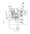
- Fig. 1 shows an configuration of the engine.
- numeral 1 denotes the engine, 2 a carburetor, 4 a suction pipe, and 5 an exhaust pipe.
- the opening of a throttle valve 18 disposed in the carburetor 2 is controlled so that the flow rate of air supplied to each cylinder of the engine from an air cleaner 27 is controlled.
- the throttle valve 18 is provided with a throttle opening sensor 24 for producing a signal indicative of the opening of the throttle valve. This signal is supplied to a control unit 3.
- the air flow rate controlled by the opening of the throttle valve 18 is sensed by a pressure sensor 19 disposed in the suction pipe 4 as the magnitude of suction vacuum.
- This suction vacuum signal is applied to the control unit 3. Based on the suction vacuum signal and output signals from various sensors to be described later, the openings of solenoid valves 7, 8, 9 and 10 disposed in the carbureter 2 are controlled.
- the fuel supplied from a fuel pump 29 is fed to the carbureter 2 from a main nozzle 12 through a main jet nozzle 11.
- the fuel is fed to the carbureter 2 from the main nozzle 12 through the main solenoid valve 8 while bypassing the main jet nozzle 11. Accordingly, the amount of fuel supplied from the main nozzle 12 can be controlled by the opening duration of the main solenoid valve 8.
- the fuel is further supplied from a slow fall bypass hole 13. The amount of supply therethrough can be controlled by changing the opening duration of the slow solenoid valve 7 to control the air flow rate through an air intake port.
- the fuel solenoid valve located at the carbureter 2 functions to increase the amount of fuel supplied and it is energized when much fuel is necessary such as at the start of the engine or during the warming up. By controlling the fuel solenoid valve 9, the fuel is supplied from the opening 14.
- the air solenoid valve located at the carbureter 2 functions to control the amount of air fed to the engine 1, the air being supplied from the opening 15.
- valve open times of the solenoids valves 7, 8, 9 and 10 are controlled for the engine control such as air to fuel ratio control and warming up operation so that the amounts of air and fuel are finely controlled.
- Numeral 17 denotes an exhaust gas recycle (EGR) valve, which is a control valve for taking out a portion of exhaust gas burnt in the cylinders of the engine and exhausted to atmosphere through the exhaust pipe 5 and the tri-system catalyst 6, from the exhaust pipe 5 and reflow it to the suction pipe 4 by an EGR pipe 28 connected to the EGR valve 17.
- the reflow of the exhaust gas is effected to improve the exhaust gas.
- a reflow ratio of the exhaust gas is controlled by the EGR valve 17 and an EGR solenoid 16 which controls the EGR valve 17.
- Numeral 25 denotes an ignition coil
- 26 denotes a distributor.
- Numeral 20 denotes a coolant temperature sensor and 22 denotes a suction air temperature sensor.
- the former is used to provide a correction signal for increasing the concentration of the fuel in order to rapidly raise the engine temperature immediately after the start of the engine while the latter produces a correction signal for the engine control, which signal is given to the control unit 3.
- Numeral 21 denotes an 0 2 sensor which is one of the important sensors for the control of the present invention. It functions to sense the oxygen content in the exhaust gas to optimize the air to fuel ratio.
- Fig. 2 shows a configuration of the control unit 3 for the engine having the carburetor.
- the control unit 3 comprises a central processor (CPU) 30, a read only memory (ROM) 31, a randam access memory (RAM) 32 and an I/0 control unit 33.
- the CPU 30 issues instructions for selectively receiving a multiplicity of external information necessary for the control of the operation to be described later and executes arithmetic operations in accordance with the contents of the ROM 31 which stores a system control program and various data and the contents of the RAM 32 which is readable and writable.
- the I/O control unit 33 comprises a digital switch 35 (e.g., a multiplexor) which switches a multiplicity of information received from the external devices in accordance with selection commands, A/D converters 36 and 37 for converting the selected analog information to digital information and a control logic circuit 39 for applying the digital information to the CPU 30 to cause it to execute arithmetic operation in accordance with the contents stored in the ROM 31 and providing control signals to the external control unit.
- a digital switch 35 e.g., a multiplexor
- A/D converters 36 and 37 for converting the selected analog information to digital information
- control logic circuit 39 for applying the digital information to the CPU 30 to cause it to execute arithmetic operation in accordance with the contents stored in the ROM 31 and providing control signals to the external control unit.
- an air to fuel ratio control unit 40 which comprises the slow solenoid valve 7 and the main solenoid valve 8 shown in Fig. 1.
- the amounts of air and fuel which determine the air to fuel ratio are controlled by the open periods of the valves 7 and 8.
- the amount of fuel of the engine is controlled, as a whole, in accordance with input information described below.
- a battery voltage sensor 44 senses the change in a battery voltage.
- the coolant temperature sensor 20 produces a signal which is a principal parameter during the idling operation. It is used to raise the concentration of the air-fuel mixture when the coolant temperature is low to render the engine to be operated at a high rotation speed.
- the coolant temperature signal is also used to control the air to fuel ratio and the exhaust gas reflow.
- the opening aperture sensor 24 and the pressure sensor 19 function to control the amount of reflow of the EGR control unit and the air to fuel ratio of the air to fuel ratio control unit.
- the 0 2 sensor 21 exhaust gas sensor senses the oxygen content in the exhaust gas to optimize the air to fuel ratio.
- a starter switch 45 produces a signal when the engine starts which is used as a conditioning signal after the engine has started.
- the reference angle signal generator 46 and the position signal generator 47 are included in the crank angle sensor 23 shown in Fig. 1, and they generate signals at every reference angle of the crank rotation, e.g. at every 180° position and 1° position respectively. Since they relate to the rotation speed of the engine, they represent data relating to the ignition control unit as well as various other units to be controlled.
- the signals from the battery voltage sensor 44, the coolant temperature sensor 20 and the 0 2 sensor 21 are applied to the multiplexor 35 and the selected one of them is applied to the A/D converter 36 and resulting digital data is applied to the CPU 30 via a bus line 34.
- the output from the pressure sensor 19 is converted to digital data by the A/D converter 37.
- the result of the arithmetic operation in the CPU is loaded in a register 90.
- a constant frequency signal is loaded in a register 94.
- a clock from the CPU 30 is applied to a counter 92 which counts up the clock signals. When the content of the counter 92 becomes equal to or greater than the content of the register 94, a comparator 98 produces an output which sets a flip-flop 100 and clears the counter 92.
- the slow solenoid 7 receives an "L” output from an inverter 102 while the main solenoid 8 receives an "H” output.
- the flip-flop 100 is set.
- the slow solenoid 7 receives the "L” signal from the inverter 102 while the main solenoid 8 receives the "H” signal. Accordingly, the "H" duty of the main solenoid 8 and hence the valve opening rate is determined by the content of the register 90 while the "L” duty of the slow solenoid 7 and hence the valve close rate is determined thereby.
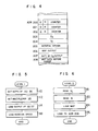
- timer interruption request is issued to start respective tasks to execute the tasks at a high priority. More particularly, when the CPU receives the interruption request, it determines at a step 50 if the interruption is the timer interruption and if it is the timer interruption the CPU selects, at a step 51, one of the tasks which are grouped in the order of priority, by a task scheduler and executes the selected task at a step 52. At a step 53, when the completion of the execution of the selected task is determined, the CPU again goes back to the step 51 where it selects the next task by the task scheduler.
- IRQ timer interruption request
- the interruption is an engine stop interruption
- the fuel pump is stopped at a step 54 and the ignition system is reset.
- the I/O control unit is rendered NO-GO.
- Table 1 shows details of the tasks grouped which are to be selected at the step 51 of the flow chart shown in Fig. 3. As seen from Table 1, the respective tasks are grouped in the order of priority as shown by levels 1 to 3 and starting timing is established depending on the priority. In the present embodiment, the starting timings of 10 milliseconds, 20 milliseconds and 40 milliseconds are established in the order of priority.
- steps 62 - 70 determine if the starting timing of the Table 1 has been reached. If yet, a Q-flag of a corresponding level shown in Fig. 4 is set to "1" at a step 66.
- address ADR 200 corresponds to the level l
- ADR 201 corresponds to the level 2
- ADR 202 corresponds to the level 3.
- the counter bits of the ADR 200 - 202 are software timers which are updated for each timer interruption to determine the timing of Table 1.
- the steps 74 - 82 determine what level of program is to be executed. Through the execution of it, the step 52 resets the Q-flag and sets an R-flag. After the completion of the task of that level, the step 53 resets the R-flag.
- Fig. 5 shows a level 1 flow which is executed at every 10 milliseconds as shown in Table 1.
- the output of the 0 2 sensor is loaded to the ADR 203 of the RAM through the A/D converter. Then the multiplexor channel selects the next sensor.
- digital data from the vacuum sensor is loaded to the address 204 of the RAM.
- the rotation speed of the output shaft of the engine is detected and it is loaded to the ADR 205 of the RAM.
- Fig. 6 shows a level 2 flow which is executed at every 20 milliseconds as shown in Table 1.
- vacuum paessure is read out of the ADR 204 of the RAM, and at a step 120, N is read out of the ADR 205 of the RAM.
- N is read out of the ADR 205 of the RAM.
- a map of the fuel valve open periods (on-duty) in the ROM is looked in accordance with the read out values and a retrieved data is loaded in the RAM 206 at a step 126.
- the solenoid values 7 and 8 of the carbureter for supplying fuel are energized at pulse duties of the applied pulses so that the fuel to be supplied is controlled by the valve open periods (on-duty) of the respective solenoid valves.
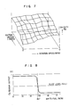
- this on-duty control is effected by presetting the on-duty factors (percents) of the respective solenoid valves such that the air to fuel ratio is equal to the stoichiometric air to fuel ratio under a condition determined by the engine rotation speed (N) and the suction vacuum (VC) sensed by the pressure sensor 19 and the position sensor 23 and calculating the on-duty factors based on the on-duty preset factors and the on-duty factors which are calculated based on the feedback signal from the 0 2 sensor.
- the on-duty factors shown in Fig. 7 is called an air to fuel ratio flat map.
- the on-duty factors for the respective solenoid valves determined by the flat map are stored in the control unit. These factors are looked in the flow shown in Fig. 6.
- the 0 2 sensor is a kind of oxygen concentration cell an electromotive force of which abruptly changes near the stoichiometric air to fuel ratio of 1.47 as shown in Fig. 8.
- rich or lean condition of the air to fuel ratio is determined, and if it is rich the duty cycle of the solenoid valve is gradually reduced and if it is lean the duty cycle is gradually increased so that a closed loop control is effected to assure that a mean air to fuel ratio is equal to the stoichiometric ratio of 1.47.
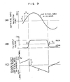
- the output voltage from the 0 2 sensor for the air to fuel ratio in the cylinder delays by a time period b as shown in Fig. 9(A). Accordingly, the output voltage waveform of the 0 2 sensor shown in Fig. 9(B) is converted to a waveform having a proportional correction component C and an integration gradient A as shown in Fig. 9(C) to compensate for the delay in order to determine a duty cycle based on the waveform shown in Fig. 9(C) such that the air to fuel ratio is controlled in average by this duty cycle.
- the embodiment of the present invention operates by the combination of the duty control based on the flat map and the feedback control based on the 0 2 sensor.
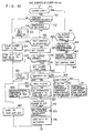
- the control method is now explained with reference to a flow chart shown in Fig. 10.
- a step 150 determines if it is an air to fuel ratio control loop or a closed loop. If it is determined non-closed loop at the step 150, a step 151 determines if the engine coolant temperature is equal to or above 40°C or not, and if it is not a step 154 clears a closed loop flag and a step 155 loads a value on the air to fuel ratio flat map to an actuator (to determine the duty cycle of the solenoid value). This operation is repeated until the engine coolant temperature reaches the predetermined temperature (40°C).
- a step 152 determines if it is immediately after the start or not, and if yes a step 153 sets a wait counter to wait until the temperature of the 0 2 sensor rises to an activation temperature (for about 10 seconds in the present embodiment). For this period, the air to fuel ratio control is effected by the duty cycle control based on the flat map value like in the previous case. Even during the operation of the wait counter at the step 153, the flat map value is read at a step 155 and it is loaded to the register 70 shown in Fig. 1. In this manner the control based on the flat map is effected.
- This value is also loaded to the address 207 of the RAM at a step 180.
- the open loop control or the flat map control is effected from the time immediately after the start of the engine through the period of temperature rise of the coolant to the time at which the 0 2 sensor can fully function.
- a step 157 sets dizzer.
- the dizzer forcedly and periodically changes the duty output for cleaning and stabilizing the 0 2 sensor to intentionally change the 0 2 sensor output to the voltages corresponding to the rich and lean conditions.
- a step 158 determines if the variation of the output exceeds a predetermined range, and if yes a step 159 sets a closed loop control start flag.
- the dizzer is stopped.
- a step 161 determines if the amplitude of the 0 2 sensor is lower than a predetermined level, or not and, if it is higher than the predetermined level a step 162 determines if the 0 2 sensor has been adhered to one side (rich or lean side) for a predetermined time period or longer. That is, it determines if the 0 2 sensor is in abnormal state or not. If the step 162 determines that the 0 2 sensor has been adhered to rich or lean side for the predetermined time period or longer, that is, the 0 2 sensor is in abnormal state, the control is immediately switched to an open loop control and a step 154 is carried out.
- the step 163 measures the engine rotation speed and a step 164 sets a control gain which corresponds to the rise of the portion C and the gradient of the portion A shown in Fig. 9(C).
- the setting of the control gain at the step 164 is effected to compensate for the delay of the detection by the 0 2 sensor and enhance the stability of the control (prevention of hunting) and the setting value depends on the engine rotation speed-.
- a step 165 and the following steps are ones for converting the change of the output signal of the 0 2 sensor shown in Fig. 9(B) to a control gain determined by the engine rotation speed, that is, to the waveform having the proportional portion C and the integration portion A shown in Fig. 9(C).
- the step 165 determines if the 0 2 sensor output is equal to or higher than a slice level S/L or not based on Figs. 9(B) and (C), and if the 0 2 sensor output is equal to or higher than the slice level S/L, a step 169 determines if the direction of change is to the lean state or to the rich state.
- a step 171 substracts a value corresponding to the proportional portion C at a time point of the change from the lean state to the rich state from the content at the address 207 of the RAM. If the step 169 determines that the state has been remaining in the lean state, a step 170 subtracts a value corresponding to the integration portion A from the content of the address 207 of the RAM.
- a step 166 determines if the 0 2 sensor output has changed in the direction from the rich state to the lean state with respect to the slice level S/L or not, and if it determines that the 0 2 sensor output has changed in the direction from the rich state to the lean state (an arrow E shown in Fig. 9(C)), a step 168 add the value corresponding to the proportional portion C to the content of the address 207 of the RAM. If the step 166 determines that the state has been remaining in the rich state, a step 167 adds the value corresponding to the integration portion A to the content of the address 207 of the step 167.
- the output waveform of the 0 2 sensor is converted to the waveform shown in Fig. 9(C).
- the duty control of the solenoid values is effected based on this waveform, but when the operation condition of the engine, that is, acceleration or deceleration condition changes abruptly, the following steps prevents the delay of the air to fuel ratio control due to the abrupt change of the operation condition.
- a step 172 calculates a change on the air to fuel ratio map due to the abrupt change of the operation condition of the engine and a step 173 adds this change to the on-duty value determined by the signal from the 0 2 sensor.
- a step 174 loads the sum to the register 90 shown in Fig. 1 which functions as the actuator.
- Fig. 11 shows details of the steps 172, 173 and 174 shown in Fig. 10. Assuming that the operation condition has changed from a point P to a point Q on the air to fuel ratio-flat map shown in Fig. 12 by the abrupt change of the operation condition, a step 175 in Fig. 11 calculates an increment ⁇ D between the data at the point P on the air to fuel ratio flat map and the data at the point Q and a step 176 adds the increment ⁇ D to the content of the address 207 of the RAM which represents the duty determined by the 0 2 sensor. A step 177 loads the sum which represents an duty output to the register 90 which functions as an external actuator (i.e. the solenoid valve in the present embodiment). The data at the point Q is temporarily stored at the address 208 of the RAM for use as the past data in the calculation for the next timer interruption.
- a step 175 in Fig. 11 calculates an increment ⁇ D between the data at the point P on the air to fuel ratio flat map and the data at the point Q and
- a waveform R for effecting the duty control based on the signal of the 0 2 sensor is generally controlled around the duty value at the point P on the fat map. If the state changes from P to Q at a point S, the increment ⁇ D between the points P and Q is calculated and it is immediately added to the waveform R which is duty-controlled by the 0 2 sensor. Accordingly, after the change the duty control is effected around the point Q.
- the primary duty control is effected based on the feedback signal from the 0 2 sensor.
- the on-duty factor (percent) calculated from the air to fuel ratio flat map is previously stored in the ROM and the operation condition of the engine is monitored by the map, and the increment calculated is added to the duty factor determined by the signal from the 0 2 sensor. Accordingly, even if the operation condition changes abruptly, the air to fuel ratio control can readily follow the change.
- the air to fuel ratio is controlled based on the data on the flat map. If the 0 2 sensor is in an abnormal state such as break of wire during the normal operation of the engine, the air to fuel ratio is automatically controlled by the flat map. Accordingly, a precise air to fuel ratio control is attained under any operation condition of the engine.
- the air to fuel ratio can be controlled precisely to follow the abrupt change of the operation condition of the engine.
Applications Claiming Priority (2)
| Application Number | Priority Date | Filing Date | Title |
|---|---|---|---|
| JP9153679A JPS5618049A (en) | 1979-07-20 | 1979-07-20 | Electronic control method for internal combustion engine |
| JP91536/79 | 1979-07-20 |
Publications (2)
| Publication Number | Publication Date |
|---|---|
| EP0023632A1 true EP0023632A1 (fr) | 1981-02-11 |
| EP0023632B1 EP0023632B1 (fr) | 1984-11-07 |
Family
ID=14029175
Family Applications (1)
| Application Number | Title | Priority Date | Filing Date |
|---|---|---|---|
| EP80104154A Expired EP0023632B1 (fr) | 1979-07-20 | 1980-07-16 | Procédé de régulation de la quantité de carburant fournie à un moteur |
Country Status (4)
| Country | Link |
|---|---|
| US (1) | US4373187A (fr) |
| EP (1) | EP0023632B1 (fr) |
| JP (1) | JPS5618049A (fr) |
| DE (1) | DE3069595D1 (fr) |
Cited By (4)
| Publication number | Priority date | Publication date | Assignee | Title |
|---|---|---|---|---|
| EP0065771A2 (fr) * | 1981-05-22 | 1982-12-01 | Hitachi, Ltd. | Appareil d'injection de combustible |
| EP0134547A2 (fr) * | 1983-08-08 | 1985-03-20 | Hitachi, Ltd. | Méthode de commande d'injection de carburant dans un moteur |
| GB2182174A (en) * | 1985-09-30 | 1987-05-07 | Honda Motor Co Ltd | Air/fuel ratio control for an internal combustion engine |
| AU705333B2 (en) * | 1995-12-01 | 1999-05-20 | Minntech Corporation | Room temperature sterilant for medical devices |
Families Citing this family (24)
| Publication number | Priority date | Publication date | Assignee | Title |
|---|---|---|---|---|
| DE3100825A1 (de) * | 1981-01-14 | 1982-08-12 | Robert Bosch Gmbh, 7000 Stuttgart | Einrichtung zum steuern der zuend- und/oder kraftstoffeinspritz- und/oder getriebeschaltvorgaenge bei brennkraftmaschinen |
| JPS57143136A (en) * | 1981-02-26 | 1982-09-04 | Toyota Motor Corp | Method of controlling air fuel ratio of internal combustion engine |
| JPS57148039A (en) * | 1981-03-10 | 1982-09-13 | Nissan Motor Co Ltd | Altitude corrector for engine fuel feeder |
| JPS57191436A (en) * | 1981-05-19 | 1982-11-25 | Automob Antipollut & Saf Res Center | Air-fuel ratio control device |
| JPS5827849A (ja) * | 1981-08-13 | 1983-02-18 | Toyota Motor Corp | 内燃機関の空燃比制御方法 |
| JPS5866108A (ja) * | 1981-10-16 | 1983-04-20 | Hitachi Ltd | 内燃機関の電子制御装置 |
| JPS5877150A (ja) * | 1981-10-30 | 1983-05-10 | Nissan Motor Co Ltd | エンジンの空燃比制御装置 |
| JPS58150039A (ja) * | 1982-03-03 | 1983-09-06 | Toyota Motor Corp | 電子制御機関の空燃比の学習制御方法 |
| JPS58206838A (ja) * | 1982-05-28 | 1983-12-02 | Hitachi Ltd | 燃料供給方法 |
| JPS59549A (ja) * | 1982-06-24 | 1984-01-05 | Toyota Motor Corp | 内燃機関のデジタル制御方法 |
| DE3401362C3 (de) * | 1983-02-04 | 1998-03-26 | Fev Motorentech Gmbh | Verfahren zur Steuerung von Viertakt-Kolbenbrennkraftmaschinen |
| JPS59196946A (ja) * | 1983-04-22 | 1984-11-08 | Mitsubishi Motors Corp | 内燃機関の空燃比制御装置 |
| JPS59208141A (ja) * | 1983-05-12 | 1984-11-26 | Toyota Motor Corp | 電子制御エンジンの空燃比リ−ン制御方法 |
| JPS6125950A (ja) * | 1984-07-13 | 1986-02-05 | Fuji Heavy Ind Ltd | 自動車用エンジンの電子制御方式 |
| JPS6128738A (ja) * | 1984-07-17 | 1986-02-08 | Fuji Heavy Ind Ltd | 自動車用エンジンの電子制御方式 |
| DE3438175A1 (de) * | 1984-10-18 | 1986-04-24 | Robert Bosch Gmbh, 7000 Stuttgart | Einrichtung zur regelung des ladedrucks einer brennkraftmaschine |
| JPS61169635A (ja) * | 1985-01-23 | 1986-07-31 | Hitachi Ltd | 空燃比制御方法 |
| JPH0478040U (fr) * | 1990-11-21 | 1992-07-08 | ||
| JPH08121220A (ja) * | 1994-10-21 | 1996-05-14 | Sanshin Ind Co Ltd | エンジンの燃焼制御装置 |
| US5794605A (en) * | 1995-03-07 | 1998-08-18 | Sanshin Kogyo Kabushiki Kaisha | Fuel control for marine engine |
| US5746183A (en) * | 1997-07-02 | 1998-05-05 | Ford Global Technologies, Inc. | Method and system for controlling fuel delivery during transient engine conditions |
| DE19748745A1 (de) * | 1997-11-05 | 1999-05-20 | Bosch Gmbh Robert | Verfahren zum Betreiben einer Brennkraftmaschine insbesondere eines Kraftfahrzeugs |
| EP3131976B1 (fr) | 2014-04-18 | 2019-02-06 | Tarkett GDL | Revêtement de polyuréthane durci par rayonnement actinique pour revêtements de surface décoratifs |
| US11547964B2 (en) * | 2019-08-07 | 2023-01-10 | Caterpillar Inc. | Actuated air filter dust valve |
Citations (10)
| Publication number | Priority date | Publication date | Assignee | Title |
|---|---|---|---|---|
| US3906910A (en) * | 1973-04-23 | 1975-09-23 | Colt Ind Operating Corp | Carburetor with feedback means and system |
| DE2603858A1 (de) * | 1975-02-05 | 1976-08-19 | Nissan Motor | Vergaser fuer kraftfahrzeugmotoren |
| US4052968A (en) * | 1974-08-19 | 1977-10-11 | Nippon Soken, Inc. | Air-to-fuel ratio adjusting system for an internal combustion engine |
| US4056932A (en) * | 1974-11-01 | 1977-11-08 | Nissan Motor Co., Ltd. | Control system for promoting catalytic removal of noxious components from exhaust gas of internal combustion engine |
| DE2318793B2 (de) * | 1972-04-14 | 1977-12-22 | Nissan Motor Co, Ltd, Yokohama, Kanagawa (Japan) | Vorrichtung zur regelung des luft/kraftstoffverhaeltnisses im luft/kraftstoff-gemisch einer brennkraftmaschine |
| US4103695A (en) * | 1974-11-06 | 1978-08-01 | Nissan Motor Company, Limited | Method of and device for controlling solenoid operated flow control means |
| US4103649A (en) * | 1975-06-17 | 1978-08-01 | Nippondenso Co., Ltd. | Method and system for controlling the mixture air-to-fuel ratio |
| US4114372A (en) * | 1975-06-13 | 1978-09-19 | Nissan Motor Company, Limited | Internal combustion engine with air-fuel ratio control device |
| US4134375A (en) * | 1976-05-24 | 1979-01-16 | Nissan Motor Company, Limited | Method of and system for controlling fuel/air ratio in an internal combustion engine |
| US4175103A (en) * | 1978-04-17 | 1979-11-20 | General Motors Corporation | Carburetor |
Family Cites Families (9)
| Publication number | Priority date | Publication date | Assignee | Title |
|---|---|---|---|---|
| GB1321989A (en) * | 1969-09-23 | 1973-07-04 | Lucas Industries Ltd | Engine control systems |
| JPS5335220A (en) * | 1976-09-13 | 1978-04-01 | Nat Jutaku Kenzai | Reinforcement arrangement device of foundation |
| US4279230A (en) * | 1977-05-06 | 1981-07-21 | Societe Industrielle De Brevets Et D'etudes S.I.B.E. | Fuel control systems for internal combustion engines |
| JPS5833385B2 (ja) * | 1977-09-12 | 1983-07-19 | トヨタ自動車株式会社 | 燃料噴射制御装置 |
| DE2750470A1 (de) * | 1977-11-11 | 1979-05-17 | Bosch Gmbh Robert | Verfahren und vorrichtung zur regelung von beim betrieb eines kraftfahrzeugs auftretenden einflussgroessen |
| JPS54158527A (en) * | 1978-06-02 | 1979-12-14 | Hitachi Ltd | Electronic type fuel control device for internal combustion engine |
| US4224910A (en) * | 1979-04-10 | 1980-09-30 | General Motors Corporation | Closed loop fuel control system with air/fuel sensor voting logic |
| US4270503A (en) * | 1979-10-17 | 1981-06-02 | General Motors Corporation | Closed loop air/fuel ratio control system |
| US4290400A (en) * | 1980-03-17 | 1981-09-22 | General Motors Corporation | Closed loop fuel control system for an internal combustion engine |
-
1979
- 1979-07-20 JP JP9153679A patent/JPS5618049A/ja active Granted
-
1980
- 1980-07-16 DE DE8080104154T patent/DE3069595D1/de not_active Expired
- 1980-07-16 EP EP80104154A patent/EP0023632B1/fr not_active Expired
- 1980-07-17 US US06/169,753 patent/US4373187A/en not_active Expired - Lifetime
Patent Citations (10)
| Publication number | Priority date | Publication date | Assignee | Title |
|---|---|---|---|---|
| DE2318793B2 (de) * | 1972-04-14 | 1977-12-22 | Nissan Motor Co, Ltd, Yokohama, Kanagawa (Japan) | Vorrichtung zur regelung des luft/kraftstoffverhaeltnisses im luft/kraftstoff-gemisch einer brennkraftmaschine |
| US3906910A (en) * | 1973-04-23 | 1975-09-23 | Colt Ind Operating Corp | Carburetor with feedback means and system |
| US4052968A (en) * | 1974-08-19 | 1977-10-11 | Nippon Soken, Inc. | Air-to-fuel ratio adjusting system for an internal combustion engine |
| US4056932A (en) * | 1974-11-01 | 1977-11-08 | Nissan Motor Co., Ltd. | Control system for promoting catalytic removal of noxious components from exhaust gas of internal combustion engine |
| US4103695A (en) * | 1974-11-06 | 1978-08-01 | Nissan Motor Company, Limited | Method of and device for controlling solenoid operated flow control means |
| DE2603858A1 (de) * | 1975-02-05 | 1976-08-19 | Nissan Motor | Vergaser fuer kraftfahrzeugmotoren |
| US4114372A (en) * | 1975-06-13 | 1978-09-19 | Nissan Motor Company, Limited | Internal combustion engine with air-fuel ratio control device |
| US4103649A (en) * | 1975-06-17 | 1978-08-01 | Nippondenso Co., Ltd. | Method and system for controlling the mixture air-to-fuel ratio |
| US4134375A (en) * | 1976-05-24 | 1979-01-16 | Nissan Motor Company, Limited | Method of and system for controlling fuel/air ratio in an internal combustion engine |
| US4175103A (en) * | 1978-04-17 | 1979-11-20 | General Motors Corporation | Carburetor |
Non-Patent Citations (3)
| Title |
|---|
| AUTOMOBILTECHNISCHE ZEITSCHRIFT, Vol. 80, No. 9, September 1978, G. HARTEL "Vergaser mit elektronischem Regeleingriff" page 400. * |
| PATENTS ABSTRACTS OF JAPAN Vol. 1, No. 144, 24 November 1977 page 5200M77 & JP - A - 52 - 89729. * |
| PATENTS ABSTRACTS OF JAPAN Vol. 1, No. 74, 16 July 1977 page 1379M77 & JP - A - 52 - 19825. * |
Cited By (7)
| Publication number | Priority date | Publication date | Assignee | Title |
|---|---|---|---|---|
| EP0065771A2 (fr) * | 1981-05-22 | 1982-12-01 | Hitachi, Ltd. | Appareil d'injection de combustible |
| EP0065771A3 (en) * | 1981-05-22 | 1983-12-07 | Hitachi, Ltd. | Fuel injection apparatus |
| EP0134547A2 (fr) * | 1983-08-08 | 1985-03-20 | Hitachi, Ltd. | Méthode de commande d'injection de carburant dans un moteur |
| EP0134547A3 (en) * | 1983-08-08 | 1985-12-27 | Hitachi, Ltd. | Method of fuel injection control in engine |
| GB2182174A (en) * | 1985-09-30 | 1987-05-07 | Honda Motor Co Ltd | Air/fuel ratio control for an internal combustion engine |
| GB2182174B (en) * | 1985-09-30 | 1989-09-06 | Honda Motor Co Ltd | Air intake side secondary air supply system for an internal combustion engine with a duty ratio control operation |
| AU705333B2 (en) * | 1995-12-01 | 1999-05-20 | Minntech Corporation | Room temperature sterilant for medical devices |
Also Published As
| Publication number | Publication date |
|---|---|
| US4373187A (en) | 1983-02-08 |
| EP0023632B1 (fr) | 1984-11-07 |
| DE3069595D1 (en) | 1984-12-13 |
| JPS6256345B2 (fr) | 1987-11-25 |
| JPS5618049A (en) | 1981-02-20 |
Similar Documents
| Publication | Publication Date | Title |
|---|---|---|
| EP0023632A1 (fr) | Procédé de régulation de la quantité de carburant fournie à un moteur | |
| US4290107A (en) | Electronic fuel control system for an internal combustion engine | |
| US4244023A (en) | Microprocessor-based engine control system with acceleration enrichment control | |
| JPH0363654B2 (fr) | ||
| US4450815A (en) | Internal combustion engine control apparatus | |
| US4354238A (en) | Method of controlling air-fuel ratio of internal combustion engine so as to effectively maintain the air fuel ratio at a desired air-fuel ratio of λ=1 | |
| EP0130382A1 (fr) | Procédé d'injection de carburant dans un moteur | |
| JPH0522061B2 (fr) | ||
| US4363307A (en) | Method for adjusting the supply of fuel to an internal combustion engine for an acceleration condition | |
| GB2141839A (en) | Automatic control of the air-fuel mixture ratio in an internal combustion engine | |
| US4721082A (en) | Method of controlling an air/fuel ratio of a vehicle mounted internal combustion engine | |
| US4290400A (en) | Closed loop fuel control system for an internal combustion engine | |
| US4656989A (en) | System for driving solenoid valve for internal combustion engine | |
| US4245312A (en) | Electronic fuel injection compensation | |
| EP0106366B1 (fr) | Méthode de controle pour moteurs à combustion interne | |
| EP0092828A2 (fr) | Appareil de commande d'injection de carburant pour moteur à combustion interne | |
| US4690121A (en) | Air intake side secondary air supply system for an internal combustion engine with a duty ratio control operation | |
| US4528964A (en) | Fuel injection control apparatus for internal combustion engine | |
| US4763265A (en) | Air intake side secondary air supply system for an internal combustion engine with an improved duty ratio control operation | |
| JPH0217703B2 (fr) | ||
| US5069182A (en) | Ignition timing control apparatus for an engine | |
| JPS60249651A (ja) | 電子制御式燃料噴射装置 | |
| JPH0689686B2 (ja) | エンジンの空燃比制御装置 | |
| KR840001327B1 (ko) | 엔진의 연료 제어방법 | |
| US4715352A (en) | Air intake side secondary air supply system for an internal combustion engine with a duty ratio control operation |
Legal Events
| Date | Code | Title | Description |
|---|---|---|---|
| PUAI | Public reference made under article 153(3) epc to a published international application that has entered the european phase |
Free format text: ORIGINAL CODE: 0009012 |
|
| AK | Designated contracting states |
Designated state(s): DE FR GB |
|
| 17P | Request for examination filed |
Effective date: 19810421 |
|
| GRAA | (expected) grant |
Free format text: ORIGINAL CODE: 0009210 |
|
| AK | Designated contracting states |
Designated state(s): DE FR GB |
|
| REF | Corresponds to: |
Ref document number: 3069595 Country of ref document: DE Date of ref document: 19841213 |
|
| ET | Fr: translation filed | ||
| PLBE | No opposition filed within time limit |
Free format text: ORIGINAL CODE: 0009261 |
|
| STAA | Information on the status of an ep patent application or granted ep patent |
Free format text: STATUS: NO OPPOSITION FILED WITHIN TIME LIMIT |
|
| 26N | No opposition filed | ||
| PGFP | Annual fee paid to national office [announced via postgrant information from national office to epo] |
Ref country code: FR Payment date: 19910620 Year of fee payment: 12 |
|
| PGFP | Annual fee paid to national office [announced via postgrant information from national office to epo] |
Ref country code: GB Payment date: 19910624 Year of fee payment: 12 |
|
| PGFP | Annual fee paid to national office [announced via postgrant information from national office to epo] |
Ref country code: DE Payment date: 19910930 Year of fee payment: 12 |
|
| PG25 | Lapsed in a contracting state [announced via postgrant information from national office to epo] |
Ref country code: GB Effective date: 19920716 |
|
| GBPC | Gb: european patent ceased through non-payment of renewal fee |
Effective date: 19920716 |
|
| PG25 | Lapsed in a contracting state [announced via postgrant information from national office to epo] |
Ref country code: FR Effective date: 19930331 |
|
| PG25 | Lapsed in a contracting state [announced via postgrant information from national office to epo] |
Ref country code: DE Effective date: 19930401 |
|
| REG | Reference to a national code |
Ref country code: FR Ref legal event code: ST |