EP0014937B2 - Anschlussvorrichtung für Bandkabel - Google Patents
Anschlussvorrichtung für Bandkabel Download PDFInfo
- Publication number
- EP0014937B2 EP0014937B2 EP80100695A EP80100695A EP0014937B2 EP 0014937 B2 EP0014937 B2 EP 0014937B2 EP 80100695 A EP80100695 A EP 80100695A EP 80100695 A EP80100695 A EP 80100695A EP 0014937 B2 EP0014937 B2 EP 0014937B2
- Authority
- EP
- European Patent Office
- Prior art keywords
- longitudinal walls
- base part
- flat cable
- base portion
- contact elements
- Prior art date
- Legal status (The legal status is an assumption and is not a legal conclusion. Google has not performed a legal analysis and makes no representation as to the accuracy of the status listed.)
- Expired
Links
- 239000004020 conductor Substances 0.000 claims abstract description 6
- 239000011810 insulating material Substances 0.000 claims abstract description 6
- 230000000295 complement effect Effects 0.000 description 1
- 238000003780 insertion Methods 0.000 description 1
- 230000037431 insertion Effects 0.000 description 1
- 238000009413 insulation Methods 0.000 description 1
- 230000035515 penetration Effects 0.000 description 1
- 230000001681 protective effect Effects 0.000 description 1
Images
Classifications
-
- H—ELECTRICITY
- H01—ELECTRIC ELEMENTS
- H01R—ELECTRICALLY-CONDUCTIVE CONNECTIONS; STRUCTURAL ASSOCIATIONS OF A PLURALITY OF MUTUALLY-INSULATED ELECTRICAL CONNECTING ELEMENTS; COUPLING DEVICES; CURRENT COLLECTORS
- H01R12/00—Structural associations of a plurality of mutually-insulated electrical connecting elements, specially adapted for printed circuits, e.g. printed circuit boards [PCB], flat or ribbon cables, or like generally planar structures, e.g. terminal strips, terminal blocks; Coupling devices specially adapted for printed circuits, flat or ribbon cables, or like generally planar structures; Terminals specially adapted for contact with, or insertion into, printed circuits, flat or ribbon cables, or like generally planar structures
- H01R12/70—Coupling devices
- H01R12/77—Coupling devices for flexible printed circuits, flat or ribbon cables or like structures
- H01R12/78—Coupling devices for flexible printed circuits, flat or ribbon cables or like structures connecting to other flexible printed circuits, flat or ribbon cables or like structures
Definitions
- the invention relates to a connecting device for ribbon cables according to the preamble of the claim.
- a connecting device for ribbon cables is known from DE-A1 2540550.
- this connection device wire branching
- the bridge part referred to there as the guide body forms a module which is initially not connected to the other two parts.
- connection device for ribbon cables (connectors for flat cables) is known, in which the two essential parts of the device (base member and cover member) can be connected to one another in a first latching position, in which the ribbon cable is connected to one by the two Parts formed guide slot can be inserted.
- the ends of the contact elements provided for penetration into the ribbon cable protrude into the guide slot, the height of the guide slot must be dimensioned such that the risk of the ribbon cable getting caught on the contact elements can be avoided.
- a connection device for ribbon cables in which a first housing half of the device is equipped with the contact elements, and in which a second housing half on the one hand forms a push-through slot for the ribbon cable and on the other hand passage openings for those with the ribbon cable in Has sections to be connected to the contact elements.
- the guide or push-through slot for the ribbon cable can thus be dimensioned very narrowly and the cable can thereby be guided precisely without fear of the cable becoming caught on parts of the contact elements protruding into the push-through slot.
- one of the locking positions between the upper part and the base part can advantageously be selected so that in this position the upper part and the base part are connected, but the push-through slot for the ribbon cable in the base part is free of the sections of the contact elements protruding from the upper part, so that Ribbon cable can be inserted unhindered into the slot.
- the contact elements fixed in the upper part are well protected against external influences, since they are enclosed by the longitudinal walls of the upper part and the longitudinal and transverse walls of the bridge part.
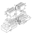
- the figure shows the device with the base part and upper part detached from one another in an oblique view, enlarged and with middle regions cut out from the upper part and base part.
- both base part 1 and upper part 6 are essentially strip-shaped insulating material bodies which are arranged transversely to the course of a ribbon cable, not shown.
- the base part 1 has a support surface 2 for the ribbon cable, into which slots 15 for receiving the tips of fork contacts (not shown) are machined transversely to the ribbon cable run, each contacting a single-cell cable between them in pairs and thereby piercing the insulating sleeve of the ribbon cable.
- the support surface 2 is provided with ribs 16 which run in the direction of the ribbon cable and each form a guide trough for a ribbon cable individual conductor by interacting with the ribbed surface structure of the ribbon cable.
- a bridge part 4 is connected in one piece to the base part 1 in such a way that the bridge part 4 covers the support surface 2 and, together with the latter, forms a push-through slot 3 which acts as a guide channel for the ribbon cable in the region of the support surface 2 and which is adapted to the ribbon cable.
- the upper part 6 contains parallel to each other
- Chambers 17 which penetrate the upper part at right angles to the course of the cable, contact elements which form 6 contact springs in the chambers 17 on the side 18 of the upper part facing away from the ribbon cable.
- the contact springs (not shown) can be contacted with contact knives or contact pins that can be inserted into the chambers 17 on the side 18 of the upper part.
- the contact elements form fork contacts which are arranged in the upper part in such a way that when the upper part 6 and base part 1 are joined they penetrate into the slots 15 of the support surface 2, thereby piercing a ribbon cable adjacent to the support surface 2 and into their contact slot can pinch one of the individual conductors of the ribbon cable.
- the upper part 6 is essentially U-shaped in cross-section, the U-legs being formed by upper part longitudinal walls 7 which protrude from the upper part in the direction of the base part.
- the bridge part 4 is structured like a honeycomb by transverse and longitudinal walls 19 and is covered by the upper part longitudinal walls 7 at least in a section 20 closer to the upper part 6 when the upper part 6 and base part 1 are joined together.
- the transverse and longitudinal walls 19 of the bridge part 4 complement one another with the upper part longitudinal walls 7 to form passage openings 5 which continue the chambers 17 in the upper part 6 in the base part 1.
- the passage openings 5 are open towards the support surface 2, so that the contact elements seated in the chambers 17 of the upper part 6 with sections protruding from the chambers 17 can penetrate into the passage openings 5 of the base part 1 when the upper part 6 and the base part 1 are joined, finally the Fork contacts of the contact elements on the side of the through openings 5 facing the ribbon cable emerge from these and partially protrude into the slots 15 of the contact surface 2 while contacting a single-cell cable.
- connection of the upper part 6 and the base part 1 is effected with the aid of hook-like locking projections 8, which are provided on the transverse walls 19 of the bridge part 4 and, when the upper part 6 and the base part 1 are joined together, snap into windows 9 which act as locking recesses and which snap into the upper part longitudinal walls 7 are incorporated. Since the upper part longitudinal walls 7 have a certain elasticity, the projections 8 can spread the upper part longitudinal walls 7 slightly apart before they snap into the windows 9.
- the contact elements seated in the upper part project with their fork contacts over the upper part longitudinal walls 7 in the direction of the base part 1.
- the upper part 6 can be connected to the base part 1 even before a ribbon cable is inserted into the push-through slot 3.
- a post 10 projecting from the base part 1 in the direction of the upper part 6 from the base part 1 is provided on both sides of the push-through slot 3, the length of which is dimensioned such that it protrudes beyond the bridge part 4 from the base part 1.
- Guide recesses 25 provided on the end faces 24 of the upper part 6 cooperate with latching hooks 11 which act as latching projections and are provided on the mutually facing sides of the posts 10.
- the posts 10 are initially slightly spread apart.
- the latching hooks 11 of the posts 10 can reach the guide recesses 25 on the upper part 6 via transverse ribs 27 of the upper part 6.
- the latching hooks 11 rest with their surfaces facing the base part 1 on the side 13 of the ribs 27 facing away from the base part.
- the upper part 6 is held in an upper locking position in the direction of the base part 1 by the locking projections 8 and in the opposite direction by the locking hooks 11.
- the posts 10 are also offset towards the longitudinal center of the base part to one side, they prevent the upper part 6 from being accidentally connected to the base part 1 by 180 °.
- the upper part 6 is pressed against the base part 1 from the upper latching position, the upper part longitudinal walls 7, which are elastic to a certain extent, are slightly spread apart by the latching projections 8 on the bridge part 4 until the further one Approach of the upper part 6 to the base part 1, snap the locking projections 8 into the windows 9 on the upper part.
- the fork contacts of the contact elements seated in the upper part 6 have penetrated the insulation of the ribbon cable section seated in the through-slot 2 and contacted this conductor in each case as a result of the exact assignment to a single conductor of the cable.
- connection device e.g. a contact device can be connected which contains contact pins or contact knives embedded in a strip-shaped insulating material body. If this device is provided with a protective collar surrounding the contact knife or contact pins, which has a shape corresponding to the post 10, this contact device can also be connected to the connecting device only in a single plug-in position, the posts 10 ensuring the unambiguous assignment of the contact device to the connecting device .
Landscapes
- Coupling Device And Connection With Printed Circuit (AREA)
- Multi-Conductor Connections (AREA)
- Insulated Conductors (AREA)
- Connector Housings Or Holding Contact Members (AREA)
- Details Of Connecting Devices For Male And Female Coupling (AREA)
- Connections By Means Of Piercing Elements, Nuts, Or Screws (AREA)
Priority Applications (1)
| Application Number | Priority Date | Filing Date | Title |
|---|---|---|---|
| AT80100695T ATE3681T1 (de) | 1979-02-14 | 1980-02-11 | Anschlussvorrichtung fuer bandkabel. |
Applications Claiming Priority (2)
| Application Number | Priority Date | Filing Date | Title |
|---|---|---|---|
| DE2905693A DE2905693C2 (de) | 1979-02-14 | 1979-02-14 | Anschlupvorrichtung für Bandkabel |
| DE2905693 | 1979-02-14 |
Publications (3)
| Publication Number | Publication Date |
|---|---|
| EP0014937A1 EP0014937A1 (de) | 1980-09-03 |
| EP0014937B1 EP0014937B1 (de) | 1983-06-01 |
| EP0014937B2 true EP0014937B2 (de) | 1987-05-13 |
Family
ID=6062937
Family Applications (1)
| Application Number | Title | Priority Date | Filing Date |
|---|---|---|---|
| EP80100695A Expired EP0014937B2 (de) | 1979-02-14 | 1980-02-11 | Anschlussvorrichtung für Bandkabel |
Country Status (5)
| Country | Link |
|---|---|
| EP (1) | EP0014937B2 (da) |
| AT (1) | ATE3681T1 (da) |
| DE (2) | DE2905693C2 (da) |
| DK (1) | DK61380A (da) |
| NO (1) | NO800323L (da) |
Families Citing this family (3)
| Publication number | Priority date | Publication date | Assignee | Title |
|---|---|---|---|---|
| DE3021049C2 (de) * | 1980-06-03 | 1983-05-05 | Siemens AG, 1000 Berlin und 8000 München | Anschlußvorrichtung für Bandkabel |
| DE3334615A1 (de) * | 1983-09-24 | 1985-04-11 | Wilhelm Quante Spezialfabrik für Apparate der Fernmeldetechnik GmbH & Co, 5600 Wuppertal | Stecker fuer elektrische flachkabel |
| GB2198599A (en) * | 1984-06-20 | 1988-06-15 | Trw Connectors | Insulation displacement connector |
Family Cites Families (7)
| Publication number | Priority date | Publication date | Assignee | Title |
|---|---|---|---|---|
| US3245024A (en) * | 1962-03-23 | 1966-04-05 | Evans William Robert | Separable electrical connector for plural conductors |
| GB1505364A (en) * | 1974-09-25 | 1978-03-30 | Thomas & Betts Corp | Electric connector |
| DE2519336C3 (de) * | 1975-04-30 | 1978-08-10 | Siemens Ag, 1000 Berlin Und 8000 Muenchen | AnschluBvorrichtung für Flachbandkabel |
| DE2540550A1 (de) * | 1975-09-11 | 1977-04-07 | Du Pont Nederland | Ader-verzweigung |
| IT1081631B (it) * | 1976-08-13 | 1985-05-21 | Amp Inc | Connettore elettrico |
| US4145103A (en) * | 1978-06-01 | 1979-03-20 | Litton Systems, Inc. | Connector with low profile latch |
| US4169647A (en) * | 1978-06-01 | 1979-10-02 | Litton Systems, Inc. | Integral low profile latch for a flat cable connector |
-
1979
- 1979-02-14 DE DE2905693A patent/DE2905693C2/de not_active Expired
-
1980
- 1980-02-07 NO NO800323A patent/NO800323L/no unknown
- 1980-02-11 EP EP80100695A patent/EP0014937B2/de not_active Expired
- 1980-02-11 AT AT80100695T patent/ATE3681T1/de active
- 1980-02-11 DE DE8080100695T patent/DE3063562D1/de not_active Expired
- 1980-02-13 DK DK61380A patent/DK61380A/da not_active Application Discontinuation
Also Published As
| Publication number | Publication date |
|---|---|
| DE2905693A1 (de) | 1980-08-21 |
| DE2905693C2 (de) | 1982-05-27 |
| EP0014937B1 (de) | 1983-06-01 |
| EP0014937A1 (de) | 1980-09-03 |
| ATE3681T1 (de) | 1983-06-15 |
| DE3063562D1 (en) | 1983-07-07 |
| NO800323L (no) | 1980-08-15 |
| DK61380A (da) | 1980-08-15 |
Similar Documents
| Publication | Publication Date | Title |
|---|---|---|
| DE69320598T2 (de) | Verbinder | |
| EP0286577B1 (de) | Aderverbinder für Kabeladern | |
| DE3850167T2 (de) | Elektrische Verbinderklemme für biegsame gedruckte Leiterplatte. | |
| DE2359982C2 (de) | Elektrischer Steckverbinder | |
| DE2941029C2 (da) | ||
| DE3902575C1 (da) | ||
| EP0818849A2 (de) | Ein-oder mehrpoliger Steckverbinder für Einzelleiter | |
| DE2735838C2 (de) | Elektrische Anschlußklemme und elektrisches Kabelverbindungsglied | |
| DE3435789A1 (de) | Halterungsblock zum verbinden von verbindungselementen mit der platte eines gedruckten schaltkreises | |
| DE2547166A1 (de) | Elektrische verbinderanordnung | |
| EP0774800A2 (de) | Querverbinder für Reihenklemmen | |
| EP0090317A2 (de) | Vorrichtung zum Anschluss von draht- oder litzenförmigen elektrischen Leitern an Kontaktorgane | |
| EP0736929A1 (de) | Elektrisches Kontaktelement und Kunststoffgehäuse zur Aufnahme des Kontaktelementes | |
| EP0014937B2 (de) | Anschlussvorrichtung für Bandkabel | |
| EP0230537A1 (de) | Klemmenleiste sowie Steckeinrichtung mit einer derartigen Klemmenleiste | |
| EP0537790B2 (de) | Steckverbinder für Flachbandkabel | |
| DE2706988A1 (de) | Schraubenlose anschlussklemme zur stromuebertragung von elektrischen leitern | |
| EP0175133B1 (de) | Anschlussvorrichtung für eine Mehrzahl von isolierten Adern | |
| EP0267145A2 (de) | Schneidklemm-Anschlusselement für elektrische Leiter | |
| EP0222039B1 (de) | Leiteranschluss | |
| DE3639793C1 (de) | Kabelmuffe,insbesondere Dropwire-Kabelmuffe fuer Doppelader-Dropwirekabel | |
| DE2609906B2 (de) | Lenkstockschalter für Kraftfahrzeuge mit einem die feststehenden Schaltkontakte aufweisenden flexiblen gedruckten Bandkabel | |
| DE3920367C2 (da) | ||
| DE2943578A1 (de) | Anschlussleiste | |
| EP1420481A1 (de) | Anschlusselement |
Legal Events
| Date | Code | Title | Description |
|---|---|---|---|
| PUAI | Public reference made under article 153(3) epc to a published international application that has entered the european phase |
Free format text: ORIGINAL CODE: 0009012 |
|
| AK | Designated contracting states |
Designated state(s): AT BE CH DE FR GB IT NL SE |
|
| 17P | Request for examination filed |
Effective date: 19801015 |
|
| ITF | It: translation for a ep patent filed | ||
| GRAA | (expected) grant |
Free format text: ORIGINAL CODE: 0009210 |
|
| AK | Designated contracting states |
Designated state(s): AT BE CH DE FR GB IT NL SE |
|
| REF | Corresponds to: |
Ref document number: 3681 Country of ref document: AT Date of ref document: 19830615 Kind code of ref document: T |
|
| REF | Corresponds to: |
Ref document number: 3063562 Country of ref document: DE Date of ref document: 19830707 |
|
| ET | Fr: translation filed | ||
| PGFP | Annual fee paid to national office [announced via postgrant information from national office to epo] |
Ref country code: NL Payment date: 19840229 Year of fee payment: 5 |
|
| PLBI | Opposition filed |
Free format text: ORIGINAL CODE: 0009260 |
|
| PGFP | Annual fee paid to national office [announced via postgrant information from national office to epo] |
Ref country code: BE Payment date: 19840331 Year of fee payment: 5 |
|
| 26 | Opposition filed |
Opponent name: AMPHENOL - TUCHEL ELECTRONICS GMBH Effective date: 19840301 |
|
| PGFP | Annual fee paid to national office [announced via postgrant information from national office to epo] |
Ref country code: CH Payment date: 19840524 Year of fee payment: 5 |
|
| PGFP | Annual fee paid to national office [announced via postgrant information from national office to epo] |
Ref country code: SE Payment date: 19841231 Year of fee payment: 6 |
|
| PGFP | Annual fee paid to national office [announced via postgrant information from national office to epo] |
Ref country code: AT Payment date: 19850130 Year of fee payment: 6 |
|
| PG25 | Lapsed in a contracting state [announced via postgrant information from national office to epo] |
Ref country code: CH Effective date: 19850228 |
|
| PG25 | Lapsed in a contracting state [announced via postgrant information from national office to epo] |
Ref country code: NL Effective date: 19850901 |
|
| NLV4 | Nl: lapsed or anulled due to non-payment of the annual fee | ||
| REG | Reference to a national code |
Ref country code: CH Ref legal event code: PL |
|
| PG25 | Lapsed in a contracting state [announced via postgrant information from national office to epo] |
Ref country code: AT Effective date: 19860211 |
|
| PG25 | Lapsed in a contracting state [announced via postgrant information from national office to epo] |
Ref country code: SE Effective date: 19860212 |
|
| PUAH | Patent maintained in amended form |
Free format text: ORIGINAL CODE: 0009272 |
|
| STAA | Information on the status of an ep patent application or granted ep patent |
Free format text: STATUS: PATENT MAINTAINED AS AMENDED |
|
| 27A | Patent maintained in amended form |
Effective date: 19870513 |
|
| AK | Designated contracting states |
Kind code of ref document: B2 Designated state(s): AT BE CH DE FR GB IT NL SE |
|
| BERE | Be: lapsed |
Owner name: SIEMENS A.G. BERLIN UND MUNCHEN Effective date: 19870228 |
|
| EN3 | Fr: translation not filed ** decision concerning opposition | ||
| GBPC | Gb: european patent ceased through non-payment of renewal fee | ||
| PG25 | Lapsed in a contracting state [announced via postgrant information from national office to epo] |
Ref country code: GB Effective date: 19881118 |
|
| PG25 | Lapsed in a contracting state [announced via postgrant information from national office to epo] |
Ref country code: BE Effective date: 19890228 |
|
| PGFP | Annual fee paid to national office [announced via postgrant information from national office to epo] |
Ref country code: FR Payment date: 19890228 Year of fee payment: 10 |
|
| PGFP | Annual fee paid to national office [announced via postgrant information from national office to epo] |
Ref country code: DE Payment date: 19890425 Year of fee payment: 10 |
|
| PG25 | Lapsed in a contracting state [announced via postgrant information from national office to epo] |
Ref country code: DE Effective date: 19901101 |
|
| EUG | Se: european patent has lapsed |
Ref document number: 80100695.8 Effective date: 19861022 |
|
| PG25 | Lapsed in a contracting state [announced via postgrant information from national office to epo] |
Ref country code: FR Free format text: LAPSE BECAUSE OF NON-PAYMENT OF DUE FEES Effective date: 19900228 |
|
| PLAB | Opposition data, opponent's data or that of the opponent's representative modified |
Free format text: ORIGINAL CODE: 0009299OPPO |