EP0010757B1 - Katheter mit Röntgenkontraststreifen - Google Patents
Katheter mit Röntgenkontraststreifen Download PDFInfo
- Publication number
- EP0010757B1 EP0010757B1 EP79104236A EP79104236A EP0010757B1 EP 0010757 B1 EP0010757 B1 EP 0010757B1 EP 79104236 A EP79104236 A EP 79104236A EP 79104236 A EP79104236 A EP 79104236A EP 0010757 B1 EP0010757 B1 EP 0010757B1
- Authority
- EP
- European Patent Office
- Prior art keywords
- catheter
- ray contrast
- strips
- contrast strips
- ray
- Prior art date
- Legal status (The legal status is an assumption and is not a legal conclusion. Google has not performed a legal analysis and makes no representation as to the accuracy of the status listed.)
- Expired
Links
- 239000000463 material Substances 0.000 claims description 6
- 239000012780 transparent material Substances 0.000 claims description 3
- 230000001788 irregular Effects 0.000 claims description 2
- 210000000056 organ Anatomy 0.000 description 4
- 208000007536 Thrombosis Diseases 0.000 description 1
- 230000015572 biosynthetic process Effects 0.000 description 1
- 239000002872 contrast media Substances 0.000 description 1
- 210000003238 esophagus Anatomy 0.000 description 1
- 210000003462 vein Anatomy 0.000 description 1
Images
Classifications
-
- A—HUMAN NECESSITIES
- A61—MEDICAL OR VETERINARY SCIENCE; HYGIENE
- A61M—DEVICES FOR INTRODUCING MEDIA INTO, OR ONTO, THE BODY; DEVICES FOR TRANSDUCING BODY MEDIA OR FOR TAKING MEDIA FROM THE BODY; DEVICES FOR PRODUCING OR ENDING SLEEP OR STUPOR
- A61M25/00—Catheters; Hollow probes
- A61M25/01—Introducing, guiding, advancing, emplacing or holding catheters
- A61M25/0105—Steering means as part of the catheter or advancing means; Markers for positioning
- A61M25/0108—Steering means as part of the catheter or advancing means; Markers for positioning using radio-opaque or ultrasound markers
-
- A—HUMAN NECESSITIES
- A61—MEDICAL OR VETERINARY SCIENCE; HYGIENE
- A61B—DIAGNOSIS; SURGERY; IDENTIFICATION
- A61B6/00—Apparatus or devices for radiation diagnosis; Apparatus or devices for radiation diagnosis combined with radiation therapy equipment
- A61B6/12—Arrangements for detecting or locating foreign bodies
Definitions
- the invention relates to a catheter for single use with x-ray contrast strips arranged helically in the longitudinal direction of the catheter.
- a known catheter (DE-A1-2 553 100) is provided with a strip which is opaque to X-rays and which runs straight in the longitudinal direction of the catheter.
- a straight x-ray contrast strip is narrow and cannot be clearly identified on the x-ray screen, because vessels, strands and organs can also run parallel to the catheter advanced in the vein, which due to their high density also become radiologically visible, so that the catheter is separated from it Environment in which it is laid, does not differentiate.
- the display becomes even less clear if the x-ray contrast strip is located on the back of the catheter with respect to the x-ray screen. Furthermore, the respective laying length of this catheter cannot be determined by X-ray.
- numbered ring markings are provided in addition to a longitudinally extending x-ray contrast strip. Since these are not made of X-ray contrast material, they are only visible extracorporeally. Such a display is too imprecise for a long catheter and too uncomfortable for the surgeon.
- Another known catheter (US-A-3 070 132) is equipped with a single helical x-ray contrast strip.
- a single helical X-ray contrast strip does not stand out from organs that are also radiologically visible, just like a straight X-ray contrast strip, so that it too is difficult to see.
- the invention is based on the object of designing a catheter with x-ray contrast strips in such a way that its position is differentiated and reliably recognizable on the x-ray screen independently of other organs represented by x-ray and that the length of the catheter which has been laid can also be clearly assessed.
- This object is achieved by two or more x-ray contrast strips arranged helically and offset in the longitudinal direction of the catheter, which result in a chain of intersection points lined up in the axial direction of the catheter in the projection in the projection.
- Such a catheter which is suitable for single use, in particular as a venous catheter, can be clearly traced on the basis of the chain of intersection points on the x-ray screen that can be precisely recognized in every position of the catheter, because the intersection points cannot be confused with organs which are also shown by x-ray, so that a differentiated assessment of the catheter position is possible.
- the representation of the helical X-ray contrast stripes intersecting in the projection at intersection points is improved by the double material thickness of the X-ray contrast stripes at the intersection points.
- the intersection points each result from the x-ray contrast strips running crosswise in the projected plane, the number of which per unit length in the axial direction of the catheter is determined by the mutual distance of the x-ray contrast strips and their slope.
- the radiologically recognizable division of the catheter achieved in this way can form a measure of the length of the catheter and serves as an orientation aid when advancing the catheter and when assessing its position.
- the mutual distances between the at least two x-ray contrast strips can be regular or irregular.
- the distance and the number of projected intersection points result in a metric division by appropriately selecting the helix pitch of the number of X-ray contrast strips.
- the cross section of the X-ray contrast strips within the catheter wall has any size and shape. It is only essential that the catheter with X-ray contrast strips has a homogeneous, self-contained, smooth overall surface, by means of which thrombus formation is avoided.
- the catheter is made of transparent material.
- the x-ray contrast strips consist of a material that is opaque to x-rays.
- the catheter tube is made of transparent material so that the material flowing through it is visible in the external part of the catheter.
- the cross section shown in FIG. 2 runs through the projected intersection points 1 shown in FIG. 1, and the double material thickness can be seen in the projection by crossing the sections of the contrast strips 2 and 3 on the front of the catheter with the sections 4 or 5 on the back of the catheter.
- the x-ray contrast strips 2 and 3 are in that The material of the wall 6 is embedded so that the catheter has a self-contained, homogeneous and smooth overall surface 8.
Landscapes
- Health & Medical Sciences (AREA)
- Life Sciences & Earth Sciences (AREA)
- Engineering & Computer Science (AREA)
- Biomedical Technology (AREA)
- Biophysics (AREA)
- Veterinary Medicine (AREA)
- Medical Informatics (AREA)
- Public Health (AREA)
- General Health & Medical Sciences (AREA)
- Animal Behavior & Ethology (AREA)
- Heart & Thoracic Surgery (AREA)
- Optics & Photonics (AREA)
- Radiology & Medical Imaging (AREA)
- Molecular Biology (AREA)
- Surgery (AREA)
- Pathology (AREA)
- Physics & Mathematics (AREA)
- Nuclear Medicine, Radiotherapy & Molecular Imaging (AREA)
- High Energy & Nuclear Physics (AREA)
- Pulmonology (AREA)
- Anesthesiology (AREA)
- Hematology (AREA)
- Media Introduction/Drainage Providing Device (AREA)
- Medicines Containing Antibodies Or Antigens For Use As Internal Diagnostic Agents (AREA)
- Medicines Containing Material From Animals Or Micro-Organisms (AREA)
- Materials For Medical Uses (AREA)
- Medicinal Preparation (AREA)
- Pharmaceuticals Containing Other Organic And Inorganic Compounds (AREA)
- Transition And Organic Metals Composition Catalysts For Addition Polymerization (AREA)
- Soil Working Implements (AREA)
- Fittings On The Vehicle Exterior For Carrying Loads, And Devices For Holding Or Mounting Articles (AREA)
- Investigating Or Analysing Biological Materials (AREA)
- Acyclic And Carbocyclic Compounds In Medicinal Compositions (AREA)
Description
- Die Erfindung bezieht sich auf einen Katheter zur einmaligen Verwendung mit in Längsrichtung des Katheters wendelförmig angeordneten Röntgenkontraststreifen.
- Ein bekannter Katheter (DE-A1-2 553 100) ist mit einem für Röntgenstrahlen undurchlässigen Streifen versehen, der in Längsrichtung des Katheters gerade verläuft. Ein solcher gerader Röntgenkontraststreifen Ist schmal und lässt sich am Röntgenschirm nicht eindeutig erkennen, weil parallel zu dem in der Vene vorgeschobenen Katheter auch Gefässe, Stränge und Organe verlaufen können, die wegen ihrer hohen Dichte ebenfalls röntgenologisch sichtbar werden, so dass sich der Katheter von dem Umfeld, in dem er verlegt ist, nicht differenziert abhebt. Die Darstellung wird noch undeutlicher, wenn der Röntgenkontraststreifen sich in bezug auf den Röntgenschirm auf der Rückseite des Katheters befindet. Ferner lässt sich die jeweilige Verlegelänge dieses Katheters röntgenologisch nicht ermitteln.
- Um die vorgeschobene Länge eines Röhrchens zur Speiseröhrenbehandlung (GB-A-1 178 285) zu veranschaulichen, sind zusätzlich zu einem in Längsrichtung gerade verlaufenden Röntgenkontraststreifen numerierte Ringmarkierungen vorgesehen. Da diese nicht aus Röntgenkontrastmaterial bestehen, sind sie nur extrakorporal sichtbar. Für einen langen Katheter ist eine solche Anzeige zu ungenau und für den Chirurgen zu unbequem.
- Ein weiterer bekannter Katheter (US-A-3 070 132) ist mit einem einzigen schraubenförmig verlaufenden Röntgenkontraststreifen ausgestattet. Ein einziger schraubenförmiger Röntgenkontraststreifen hebt sich jedoch von ebenfalls röntgenologisch sichtbaren Organen genausowenig ab, wie ein gerader Röntgenkontraststreifen, so dass auch er schlecht erkennbar ist. Ausserdem fehlen Anhaltspunkte für die verlegte Länge des Katheters.
- Der Erfindung liegt die Aufgabe zugrunde, einen Katheter mit Röntgenkontraststreifen so auszubilden, dass seine Lage unabhängig von anderen röntgenologisch dargestellten Organen differenziert und zuverlässig am Röntgenschirm erkennbar ist und dass dabei auch die verlegte Länge des Katheters eindeutig beurteilt werden kann.
- Diese Aufgabe wird gelöst durch zwei oder mehrere in Längsrichtung des Katheters wendelförmig und versetzt angeordnete Röntgenkontraststreifen, die in der Projektion bei der Röntgendarstellung eine in axialer Richtung des Katheters aneinandergereihte Kette von Schnittpunkten ergeben.
- Ein solcher zur einmaligen Verwendung, insbesondere als Venenkatheter, geeigneter Katheter lässt sich aufgrund der in jeder Lage des Katheters auf dem Röntgenschirm exakt erkennbaren Kette von Schnittpunkten am Röntgenschirm deutlich verfolgen, weil die Schnittpunkte nicht mit röntgenologisch ebenfalls dargestellten Organen verwechselt werden können, so dass eine differenzierte Beurteilung der Katheterlage möglich ist. Die Darstellung der sich in der Projektion an Schnittpunkten kreuzenden wendelförmigen Röntgenkontraststreifen wird durch die doppelte Materialdicke der Röntgenkontraststreifen in den Schnittpunkten verbessert. Die Schnittpunkte ergeben sich jeweils durch die in der projizierten Ebene kreuzweise verlaufenden Röntgenkontraststreifen, deren Anzahl pro Längeneinheit in axialer Richtung des Katheters vom gegenseitigen Abstand der Röntgenkontraststreifen und deren Steigung bestimmt wird. Die auf diese Weise erzielte röntgenologisch erkennbare Teilung des Katheters kann ein Mass für die verlegte Länge des Katheters bilden und dient als Orientierungshilfe beim Vorschieben des Katheters und bei der Beurteilung seiner Lage.
- Die gegenseitigen Abstände der mindestens zwei Röntgenkontraststreifen können regelmässig oder unregelmässig sein. Durch entsprechende Wahl der Wendelsteigung der Anzahl der Röntgenkontraststreifen ergeben der Abstand und die Anzahl der projizierten Schnittpunkte eine metrische Teilung.
- Der Querschnitt der Röntgenkontraststreifen innerhalb der Katheterwandung weist eine beliebige Grösse und Form auf. Es ist lediglich wesentlich, dass der Katheter mit Röntgenkontraststreifen eine homogene, in sich geschlossene, glatte Gesamtoberfläche aufweist, durch die eine Thrombenbildung vermieden wird.
- Der Katheter wird aus transparentem Material gefertigt. Die Röntgenkontraststreifen bestehen aus einem für Röntgenstrahlen undurchlässigen Werkstoff.
- Die Erfindung wird im Folgenden unter Bezugnahme auf die Zeichnungen erläutert. Es zeigt:
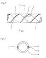
- Fig. 1 eine Draufsicht auf einen Katheter mit zwei parallel verlaufenden Röntgenkontraststreifen in der projizierten Ebene, und
- Fig. 2 einen Schnitt durch den Katheter nach Fig. 1 längs der Linie A-A.
- Durch die wendelförmige, versetzte Anordnung von zwei Röntgenkontraststreifen 2 und 3 kreuzen sich in der Projektion ihre auf der Rückseite des Katheters befindlichen Abschnitte 4 und 5 mit denen auf der Vorderseite vorhandenen gegenläufigen Abschnitten des jeweils anderen Röntgenkontraststreifens 2 bzw. 3, und es entstehen sich in regelmässigen Abständen wiederholende Schnittpunkte 1. Der Katheterschlauch besteht aus transparentem Werkstoff, so dass das ihn durchströmende Material im extern liegenden Teil des Katheters sichtbar ist.
- Der in Fig. 2 gezeigte Querschnitt verläuft durch die in Fig. 1 gezeigten projizierten Schnittpunkte 1, und es ist die doppelte Materialdicke erkennbar, die sich in der Projektion durch Kreuzung der Abschnitte der Kontraststreifen 2 bzw. 3 auf der Vorderseite des Katheters mit den Abschnitten 4 bzw. 5 auf der Rückseite des Katheters ergibt.
- Die Röntgenkontraststreifen 2 und 3 sind in das Material der Wand 6 versenkt so eingebettet, dass der Katheter eine in sich geschlossene, homogene und glatte Gesamtoberfläche 8 aufweist.
Claims (5)
Priority Applications (1)
| Application Number | Priority Date | Filing Date | Title |
|---|---|---|---|
| AT79104236T ATE1767T1 (de) | 1978-11-03 | 1979-10-31 | Katheter mit roentgenkontraststreifen. |
Applications Claiming Priority (2)
| Application Number | Priority Date | Filing Date | Title |
|---|---|---|---|
| DE19787832684U DE7832684U1 (de) | 1978-11-03 | 1978-11-03 | Katheter mit wendelfoermig angeordneten kontraststreifen zum einmaligen gebrauch |
| DE7832684U | 1978-11-03 |
Publications (2)
| Publication Number | Publication Date |
|---|---|
| EP0010757A1 EP0010757A1 (de) | 1980-05-14 |
| EP0010757B1 true EP0010757B1 (de) | 1982-11-10 |
Family
ID=6696619
Family Applications (1)
| Application Number | Title | Priority Date | Filing Date |
|---|---|---|---|
| EP79104236A Expired EP0010757B1 (de) | 1978-11-03 | 1979-10-31 | Katheter mit Röntgenkontraststreifen |
Country Status (8)
| Country | Link |
|---|---|
| EP (1) | EP0010757B1 (de) |
| JP (1) | JPS5566367A (de) |
| AT (1) | ATE1767T1 (de) |
| DE (2) | DE7832684U1 (de) |
| DK (1) | DK462279A (de) |
| ES (1) | ES485607A0 (de) |
| FI (1) | FI793426A7 (de) |
| NO (1) | NO147014C (de) |
Families Citing this family (13)
| Publication number | Priority date | Publication date | Assignee | Title |
|---|---|---|---|---|
| DE2954080C2 (de) * | 1979-03-19 | 1988-01-14 | Dr. Eduard Fresenius, Chemisch-Pharmazeutische Industrie Kg, 6380 Bad Homburg, De | |
| DE2910749C2 (de) * | 1979-03-19 | 1982-11-25 | Dr. Eduard Fresenius, Chemisch-pharmazeutische Industrie KG, 6380 Bad Homburg | Katheter mit Kontraststreifen |
| EP0033659A3 (de) * | 1980-02-04 | 1982-02-17 | Teleflex Incorporated | Medisch-chirurgischer Katheter |
| JPS5755152A (en) * | 1980-09-18 | 1982-04-01 | Toray Industries | Therapeutic molded object provided with x-ray contrasting property |
| JPS58198353A (ja) * | 1982-05-14 | 1983-11-18 | 株式会社東海メデイカルプロダクツ | 医療用チユ−ブ |
| AU4798785A (en) * | 1984-10-03 | 1986-04-10 | Baylor College Of Medicine | Implant rupture mammography |
| US4773432A (en) * | 1987-02-09 | 1988-09-27 | Schneider-Shiley (Usa) Inc. | Bail-out catheter |
| WO1999048548A1 (en) * | 1998-03-23 | 1999-09-30 | Medtronic, Inc. | Catheter having extruded radiopaque stripes embedded in soft tip and method of fabrication |
| DE10220409B4 (de) * | 2002-05-08 | 2006-03-02 | Raumedic Ag | Verwendung eines Katheterschlauches |
| DE20314393U1 (de) * | 2003-09-16 | 2004-03-04 | Campus Medizin & Technik Gmbh | Vorrichtung zum Einführen in Körperorgane mit Markierung der Lagekontrolle |
| JP4550539B2 (ja) * | 2004-10-01 | 2010-09-22 | 日本シャーウッド株式会社 | カテーテル |
| ATE516843T1 (de) | 2005-04-28 | 2011-08-15 | St Jude Medical Atrial Fibrill | Körper für einen katheter oder eine hülse |
| WO2006116719A2 (en) | 2005-04-28 | 2006-11-02 | St. Jude Medical, Atrial Fibrillation Division, Inc. | Peelable atraumatic tip and body for a catheter or sheath |
Citations (1)
| Publication number | Priority date | Publication date | Assignee | Title |
|---|---|---|---|---|
| US3070132A (en) * | 1960-04-06 | 1962-12-25 | David S Sheridan | Non-sparking medico-surgical tubes |
Family Cites Families (11)
| Publication number | Priority date | Publication date | Assignee | Title |
|---|---|---|---|---|
| US2212334A (en) * | 1936-08-15 | 1940-08-20 | Mueller & Co V | Catheter |
| DE823320C (de) * | 1950-08-15 | 1951-12-03 | Willy Ruesch | Katheter, insbesondere Intratracheal-Katheter und Verfahren zu seiner Herstellung |
| US3034510A (en) * | 1959-01-02 | 1962-05-15 | British Oxygen Co Ltd | Catheters |
| US3302635A (en) * | 1963-09-19 | 1967-02-07 | Fred E Pittman | Semi-rigid device for marking internal bleeding |
| US3375828A (en) * | 1965-04-15 | 1968-04-02 | Brunswick Corp | Suction catheter |
| GB1178285A (en) * | 1967-08-10 | 1970-01-21 | Louis Roger Celestin | Improvements in or relating to Devices for Effecting Endo-Oesophageal Intubation. |
| US3483859A (en) * | 1967-11-29 | 1969-12-16 | Fred E Pittman | String for marking bleeding in upper gastro-intestinal tract |
| US3608555A (en) * | 1968-12-31 | 1971-09-28 | Chemplast Inc | Radio opaque and optically transparent tubing |
| US3618614A (en) * | 1969-05-06 | 1971-11-09 | Scient Tube Products Inc | Nontoxic radiopaque multiwall medical-surgical tubings |
| NL7414546A (nl) * | 1973-11-15 | 1975-05-20 | Rhone Poulenc Sa | Soepele verwarmingsbuis en werkwijze voor het vervaardigen ervan. |
| GB1511269A (en) * | 1974-12-20 | 1978-05-17 | Sherwood Medical Ind Inc | Method of making a catheter with x-ray opaque markings |
-
1978
- 1978-11-03 DE DE19787832684U patent/DE7832684U1/de not_active Expired
-
1979
- 1979-10-31 EP EP79104236A patent/EP0010757B1/de not_active Expired
- 1979-10-31 DE DE7979104236T patent/DE2964029D1/de not_active Expired
- 1979-10-31 AT AT79104236T patent/ATE1767T1/de not_active IP Right Cessation
- 1979-11-01 FI FI793426A patent/FI793426A7/fi not_active Application Discontinuation
- 1979-11-01 DK DK462279A patent/DK462279A/da not_active Application Discontinuation
- 1979-11-01 ES ES485607A patent/ES485607A0/es active Granted
- 1979-11-02 NO NO793539A patent/NO147014C/no unknown
- 1979-11-02 JP JP14272879A patent/JPS5566367A/ja active Pending
Patent Citations (1)
| Publication number | Priority date | Publication date | Assignee | Title |
|---|---|---|---|---|
| US3070132A (en) * | 1960-04-06 | 1962-12-25 | David S Sheridan | Non-sparking medico-surgical tubes |
Also Published As
| Publication number | Publication date |
|---|---|
| DE2964029D1 (en) | 1982-12-16 |
| FI793426A7 (fi) | 1981-01-01 |
| ES8101897A1 (es) | 1980-12-16 |
| NO147014C (no) | 1983-01-19 |
| ATE1767T1 (de) | 1982-11-15 |
| DK462279A (da) | 1980-05-04 |
| ES485607A0 (es) | 1980-12-16 |
| DE7832684U1 (de) | 1980-04-10 |
| JPS5566367A (en) | 1980-05-19 |
| EP0010757A1 (de) | 1980-05-14 |
| NO147014B (no) | 1982-10-11 |
| NO793539L (no) | 1980-05-06 |
Similar Documents
| Publication | Publication Date | Title |
|---|---|---|
| EP0010757B1 (de) | Katheter mit Röntgenkontraststreifen | |
| DE2910749C2 (de) | Katheter mit Kontraststreifen | |
| DE2811772C2 (de) | Drainagerohr | |
| DE69805465T2 (de) | Flüssigkeitsdurchlässige Deckschicht für absorbierende Wegwerfartikel | |
| CH445752A (de) | Aufgussbeutel und Verfahren zu seiner Herstellung | |
| DE2244681A1 (de) | Auswaehl- und trennvorrichtung | |
| EP0063542B1 (de) | Sportschuh für Radfahrer | |
| DE2509784A1 (de) | Mischeinrichtung | |
| DE2557380A1 (de) | Verfahren und vorrichtung zur herstellung von doppelwandigen tropfbewaesserungsrohren aus kunststoff | |
| DE1805572C3 (de) | Urinsammelbehälter | |
| DE2708613A1 (de) | Filtereinrichtung | |
| DE827607C (de) | Lineal | |
| CH658489A5 (en) | Reinforcing mat for reinforced concrete | |
| DE2954080C2 (de) | ||
| DE2116587C3 (de) | Verfahren zum Herstellen von Matratzen aus Drahtgewebe zum Abdecken von erosionsgefährdeten Oberflächen und nach dem Verfahren vorgefertigtes Halbfabrikat zur Ausführung des Verfahrens an Ort und Stelle | |
| DE284943C (de) | ||
| DE1113209B (de) | Fraktioniervorrichtung | |
| DE2436760C2 (de) | Stacheldraht | |
| AT328670B (de) | Firstentluftung | |
| DE7716727U1 (de) | Vorrichtung mit einem durchlaessigen band fuer filtrierzwecke | |
| DE1026251B (de) | Schweissspaltsieb | |
| DE1813094C (de) | Stahlschalung zum Herstellen von Betonfertigteilen mit zwei Rippen | |
| DE1829390U (de) | Draenrohr. | |
| DE1484328C (de) | Mehrschichtiges Bauelement | |
| DE2116615A1 (de) | Füllung für Kühltürme |
Legal Events
| Date | Code | Title | Description |
|---|---|---|---|
| PUAI | Public reference made under article 153(3) epc to a published international application that has entered the european phase |
Free format text: ORIGINAL CODE: 0009012 |
|
| AK | Designated contracting states |
Designated state(s): AT BE CH DE FR GB IT LU NL SE |
|
| 17P | Request for examination filed |
Effective date: 19801008 |
|
| ITF | It: translation for a ep patent filed | ||
| GRAA | (expected) grant |
Free format text: ORIGINAL CODE: 0009210 |
|
| AK | Designated contracting states |
Designated state(s): AT BE CH DE FR GB IT LU NL SE |
|
| REF | Corresponds to: |
Ref document number: 1767 Country of ref document: AT Date of ref document: 19821115 Kind code of ref document: T |
|
| REF | Corresponds to: |
Ref document number: 2964029 Country of ref document: DE Date of ref document: 19821216 |
|
| PG25 | Lapsed in a contracting state [announced via postgrant information from national office to epo] |
Ref country code: LU Free format text: LAPSE BECAUSE OF NON-PAYMENT OF DUE FEES Effective date: 19831031 Ref country code: CH Effective date: 19831031 Ref country code: BE Effective date: 19831031 Ref country code: AT Effective date: 19831031 |
|
| PG25 | Lapsed in a contracting state [announced via postgrant information from national office to epo] |
Ref country code: SE Effective date: 19831101 |
|
| PG25 | Lapsed in a contracting state [announced via postgrant information from national office to epo] |
Ref country code: NL Effective date: 19840501 |
|
| NLV4 | Nl: lapsed or anulled due to non-payment of the annual fee | ||
| PG25 | Lapsed in a contracting state [announced via postgrant information from national office to epo] |
Ref country code: FR Free format text: LAPSE BECAUSE OF NON-PAYMENT OF DUE FEES Effective date: 19840629 |
|
| REG | Reference to a national code |
Ref country code: CH Ref legal event code: PL |
|
| PG25 | Lapsed in a contracting state [announced via postgrant information from national office to epo] |
Ref country code: DE Effective date: 19840703 |
|
| REG | Reference to a national code |
Ref country code: FR Ref legal event code: ST |
|
| PG25 | Lapsed in a contracting state [announced via postgrant information from national office to epo] |
Ref country code: GB Effective date: 19881118 |
|
| EUG | Se: european patent has lapsed |
Ref document number: 79104236.9 Effective date: 19850607 |
|
| PLBE | No opposition filed within time limit |
Free format text: ORIGINAL CODE: 0009261 |
|
| STAA | Information on the status of an ep patent application or granted ep patent |
Free format text: STATUS: NO OPPOSITION FILED WITHIN TIME LIMIT |