EP0010653B1 - Bouterolles pour double-porte - Google Patents
Bouterolles pour double-porte Download PDFInfo
- Publication number
- EP0010653B1 EP0010653B1 EP19790103869 EP79103869A EP0010653B1 EP 0010653 B1 EP0010653 B1 EP 0010653B1 EP 19790103869 EP19790103869 EP 19790103869 EP 79103869 A EP79103869 A EP 79103869A EP 0010653 B1 EP0010653 B1 EP 0010653B1
- Authority
- EP
- European Patent Office
- Prior art keywords
- latching
- receiving slots
- spring
- spring bolt
- holding
- Prior art date
- Legal status (The legal status is an assumption and is not a legal conclusion. Google has not performed a legal analysis and makes no representation as to the accuracy of the status listed.)
- Expired
Links
- 238000003780 insertion Methods 0.000 claims description 10
- 230000037431 insertion Effects 0.000 claims description 10
- 230000006835 compression Effects 0.000 claims description 9
- 238000007906 compression Methods 0.000 claims description 9
- 230000000903 blocking effect Effects 0.000 claims description 5
- 230000001154 acute effect Effects 0.000 claims description 4
- 230000000717 retained effect Effects 0.000 claims 2
- 230000007704 transition Effects 0.000 claims 1
- 230000002787 reinforcement Effects 0.000 description 4
- 230000005540 biological transmission Effects 0.000 description 2
- 238000000034 method Methods 0.000 description 2
- 238000002347 injection Methods 0.000 description 1
- 239000007924 injection Substances 0.000 description 1
- 239000002184 metal Substances 0.000 description 1
- 230000000284 resting effect Effects 0.000 description 1
Images

Classifications
-
- E—FIXED CONSTRUCTIONS
- E05—LOCKS; KEYS; WINDOW OR DOOR FITTINGS; SAFES
- E05C—BOLTS OR FASTENING DEVICES FOR WINGS, SPECIALLY FOR DOORS OR WINDOWS
- E05C7/00—Fastening devices specially adapted for two wings
- E05C7/04—Fastening devices specially adapted for two wings for wings which abut when closed
- E05C7/06—Fastening devices specially adapted for two wings for wings which abut when closed a fastening device for one wing being actuated or controlled by closing another wing
-
- Y—GENERAL TAGGING OF NEW TECHNOLOGICAL DEVELOPMENTS; GENERAL TAGGING OF CROSS-SECTIONAL TECHNOLOGIES SPANNING OVER SEVERAL SECTIONS OF THE IPC; TECHNICAL SUBJECTS COVERED BY FORMER USPC CROSS-REFERENCE ART COLLECTIONS [XRACs] AND DIGESTS
- Y10—TECHNICAL SUBJECTS COVERED BY FORMER USPC
- Y10T—TECHNICAL SUBJECTS COVERED BY FORMER US CLASSIFICATION
- Y10T292/00—Closure fasteners
- Y10T292/08—Bolts
- Y10T292/0801—Multiple
- Y10T292/0814—Double acting
- Y10T292/0818—Swinging
Definitions
- the invention relates to a locking catch for double doors with two door-side holding elements and two body-side locking elements, in which a spring accommodated in the catch housing presses the locking elements into the closed position and in which the holding element of one door is blocked in the closed position, even if the holding element of the other door is brought into the closed position.
- a locking catch of the type mentioned which ensures this locking function.
- the two locking elements are designed as slides, which are held in the catch housing in the closed positions by means of a compression spring.
- the catch housing is attached to the body so that the direction of adjustment of the slide is parallel to the open front of the body.
- the slides protrude from the latch housing with a triangular locking tip.
- Holding elements are attached to the doors, which have a triangular snap-in receptacle. If a door is closed, the holding element adjusts the slide against the force of the spring until it can then snap into the latching receptacle of the holding element in the closed position of the door.
- this known locking catch has the disadvantage that the closed doors do not fit snugly against the front edges of the body. Since the slider and the holding elements have a locking position defined in the closing direction, tolerances of the doors, the body and in the attachment of the catch housing and the holding elements cannot be compensated for.
- a locking catch is known from DE-C-701 171, in which the housing has two receiving slots for holding elements of the doors.
- One holding element is designed as a holding bolt and the other holding element as a holding eyelet.
- a slide is moved transversely to the front of the cabinet, a locking tongue of the slide being inserted into the retaining eye.
- FR-A-1 449 823 shows a catch with a single pivot lever which engages behind a retaining bolt attached to the door.
- the swivel lever is adjusted by a slide that is moved by the second door to be closed last. With this catch, too, the swivel position of the swivel lever depends on the position of the slide, so that no tolerance compensation can be achieved with the doors resting tightly against the cabinet.
- GB-A-14 11 469 shows a lock for a motor vehicle door with two pivoting lifting legs, between which a retaining bolt of the door is locked. With this lock, no two doors can be set in the desired closing and opening sequence.
- the holding elements are designed as holding bolts that can be inserted into receiving slots in the catch housing, that the locking elements are designed as locking levers pivotably mounted in the catching housing, each protruding into a receiving slot, that the locking levers when the holding bolt is inserted into the assigned receiving slots can be deflected out of these, that the inserted retaining bolts are resiliently held in the end regions of the receiving slots by the pivoted-back locking levers and that a locking lever with a blocking projection protrudes into the end region of the receiving slot assigned to the other locking lever in such a way that this locking lever is held non-pivotably by the retaining bolts inserted into this receiving slot.
- the pivoting of the locking lever projecting into the receiving slots of the catch housing is achieved in a simple manner in that the retaining bolts are aligned with their central axes perpendicular to the longitudinal axes of the receiving slots and that the receiving slots are horizontal and the retaining bolts are aligned vertically, and in that the locking levers on the insertion side of the Receiving slots are rotatably mounted between the receiving slots on a common bearing pin of the catch housing, the pivot axis being directed perpendicular to the longitudinal axes of the receiving slots. This creates enough space on the insertion side between the receiving slots that allows the locking lever to be pivoted in.
- the locking levers are held by means of the spring on stops of the catch housing arranged outside the receiving slots.
- a continuous deflection process for the locking levers when inserting and extending the retaining bolts into or out of the receiving slots is achieved in that the locking levers on the insertion side of the receiving slots are provided with pivoting bevels, by means of which the locking levers each move towards the other locking lever when the retaining bolt is inserted is pivotable and that the locking levers facing the end regions of the receiving slots are provided with bevels which form locking receptacles for the retaining bolts with the end regions of the receiving slots and hold them resiliently in these locking receptacles, and that these bevels are inclined so that even when the Holding bolt of the associated locking lever is pivotable in the direction of the other locking lever.
- the locking levers In order for the locking levers to be used for a locking catch attached to the lower edges and to the upper edges of the doors, a further development provides that the locking levers be designed symmetrically to a central plane running perpendicular to the pivot axis and therefore in two positions on the bearing journal which are reversed by 180 ° of the catch housing can be rotated. Simply by storing the locking lever, the blocking can therefore be shifted to one or the other receiving slot, as is required for double doors that are locked in the area of the lower edges and the upper edges of the doors by means of separate locking catches.
- the rotary bearing of the locking lever is carried out according to one embodiment so that a locking lever is rotatably mounted on the bearing pin by means of two spaced-apart bearing lugs, during the on. whose plate-shaped locking lever is rotatably mounted between these two mounting brackets on the trunnion of the catch housing.
- the support of the spring on the two locking levers is carried out according to one embodiment so that the locking lever with the two mounting brackets in the end bracket connecting the two mounting brackets and provided with the deflection slope and the tightening slope is provided with a blind hole which is open to the other locking lever and receives a spring designed as a coil spring.
- the width of the receiving slots is larger than the diameter of the holding bolts.
- the structure of the catch housing is preferably designed so that the catch housing consists of a box-shaped lower part, the side wall of which is provided with recesses on one side, and a box-shaped upper part, the side wall of which is provided on one side and the cover plate with the receiving slots, the receiving slots in the upper part coincide with the recesses in the lower part.
- a fastening tab is formed on the lower part of the insertion side, which is provided in the mutually parallel edges with open fastening slots designed for a predetermined hole spacing.
- a further embodiment provides that the swivel-in slopes of the locking lever in the closing direction to the longitudinal central axis of the receiving slots form an acute angle and the tightening slopes in the opening direction make an obtuse angle Include angles.
- the acute angle of the swivel-in chamfer brings one when inserting a retaining bolt Larger lever arm relative to the pivot point of the locking lever than the compression spring holding the locking lever in the starting position. Therefore, the deflection of the locking lever can be done with little force when inserting the retaining bolt.
- the return springs housed in the hinges of the hinged door may already be sufficient so that the door is practically brought into the locking position by itself.
- the obtuse angle of the bevels primarily serves to ensure that the full force of the compression spring pulls the locked door against the body.
- the lever arm acting on the retaining bolt is smaller than the lever arm of the compression spring, so that a force transmission takes place. To open the locked door, this increased force must therefore be overcome.
- the closing forces of the return springs in the hinges must also be overcome.
- the locking catch can also be used to hold a door with the same advantages, it is provided according to a further development that the catch housing is only provided with a receiving slot, that only one locking lever is rotatably mounted in the catch housing and that the compression spring on this locking lever and the catch housing supports.
- This pivot lever is achieved in that the locking lever is inserted with the blind hole and the two mounting brackets.
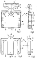
- the locking catch according to the invention is accommodated in a catch housing which is composed of the lower part 10 shown in FIGS. 1 and 2 and the upper part 30 shown in FIGS. 3 and 4.
- the lower part 10 is box-shaped, the cutouts 22 and 23 being made in one side of the side wall 16 and coinciding with the receiving slots 35 and 36 in the cover plate and the side wall 31 of the box-shaped upper part 30 when the two parts are connected to one another.
- the connection of the lower part 10 and the upper part 30 can take place via the connecting sleeves 19 formed on the lower part 10 and the connecting pins 33 formed on the upper part 30, which are clamped in the connecting sleeves 19 or otherwise held.
- Lower part 10 and upper part 30 are preferably designed as metal injection molded parts.
- the side walls 16 and 31 of the lower part 10 and upper part 30 are provided on the end face with mutually offset connecting webs 21 and 32, so that the overlapping connection between the lower part 10 and upper part 30 of the catch housing closes tightly.
- the lower part 10 and the upper part 30 form two parallel receptacles for the holding elements of the doors, not shown, which are designed as holding pins.
- These recordings are formed by the cutouts 22 and 23 in the lower part 10 and the receiving slots 35 and 36 in the upper part 30 and are thus open to one side of the catch housing.
- This page is called the introductory page.
- the side of the side wall 16 opposite the insertion side has a central recess in which the base plate of the lower part 10 is offset upwards and carries a bearing pin 17.
- This raised shoulder 18 of the base plate serves as a bearing for the locking levers to be stored in the catch housing, as will be shown.
- the raised heel 18 is continued outside the side wall 16 as a fastening tab 11.
- the edges 14 bent at right angles and the integrally formed stiffening webs 15 give the fastening flange 11 sufficient strength.
- Fastening slots 12 and 13, which are open to the outside and are matched to a predetermined hole spacing, are introduced into the edges of the fastening flange 11 which run parallel to one another.
- the catch housing can therefore be fixed to the body with the base plate of the lower part 10, holes of a row of holes made in the body being able to be used.
- a recess 37 is also made in the side wall 31 on the upper part 30 on the side facing away from the insertion side.
- the cover plate of the upper part 30 is continued in a semicircular shape, as shown by the reference numeral 34. This semi-circular part of the cover plate completes the counter bearing for the locking lever.
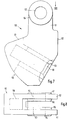
- Stops 20 are formed on the mutually opposite inner sides of the side wall 16 parallel to the receptacles, which limit the pivoting range of the locking levers 40 and 50 pivotably mounted about the bearing pin 17 and define the starting positions thereof, as shown in FIGS. 5 and 6.
- a plate-shaped locking lever 40 is rotatably mounted on the journal 17. This locking lever 40 extends into the receptacle, which is formed by the receiving slot 35 and the recess 23.
- the locking lever 50 which is also rotatably mounted on the bearing pin 17, extends into the receptacle, which is formed by the receiving slot 36 and the recess 22.
- the locking lever 50 is, as the enlarged representations according to FIGS. 7 and 8 show, rotatably mounted on the bearing pin 17 by means of two bearing brackets 51 and 52.
- the bearing plates 51 and 52 are reinforced in the area of the bearing bores 53 in a ring-like manner, as the reinforcements 54, 55, 56 and 57 show.
- the locking lever 50 is therefore supported with the reinforcement 54 on the bearing shoulder 18 of the lower part 10 and with the reinforcement 57 on the semicircular part 34 of the upper part 30.
- the locking lever 40 is supported in the region of its bearing bore 52 on the reinforcements 55 and 56 of the locking lever 50 and can therefore be pivoted between the two mounting brackets 51 and 52.
- the locking lever 50 has a blind hole 58 which is open towards the locking lever 40 and is provided with an insertion phase 63.
- a spring 60 designed as a helical spring is held in this blind hole 58 and is supported with the projecting end on a support surface 45 of the locking lever 40.
- Retaining bolts are attached to the doors as retaining elements using fastening straps.
- the retaining bolts are aligned vertically and are inserted into the catches of the catch housing when the doors are closed.
- the door hinged on the left must first be closed when closing.
- the associated retaining bolt is inserted into the receptacle formed by the recess 22 and the receiving slot 36.
- the retaining pin encounters the swivel-in slope 59 of the locking lever 50, which is pivoted counterclockwise when the retaining bolt is inserted further. If the retaining bolt has been inserted into the end region of the receiving slot 36, the locking lever 50 can be reset clockwise.
- the locking lever 50 lies with its bevel 61 against the retaining bolt and pulls it with the door against the body. If the receiving slot 36 is deep enough, it can be ensured that the door fits snugly and under tension against the front of the body.
- the associated retaining bolt pivots the locking lever 40 clockwise.
- the retaining pin deflects the locking lever 40 against the locking lever 50 via the pivoting slope 43, which is firmly again in the starting position shown, but is not yet in contact with the stop 20. If the retaining bolt has reached the end region of the receiving slot 35, then the locking lever 40 pivots counterclockwise and holds the retaining bolt resiliently via its bevel 44, so that the second door also fits snugly and under tension on the front of the body.
- the locking lever 50 protrudes with the locking lugs 62 of both mounting brackets 51 and 52 in the end region of the receiving slot 35. If the holding bolt is held over the locking lever 40 in this receiving slot 35, the locking lever 50 can no longer be pivoted, since this locking lugs 62 on the Hold bolts in place. Only when the retaining bolt is led out of the receiving slot 35 can the retaining bolt also be guided out of the receiving slot 36 by pivoting the locking lever 50.
- the bevels 44 and 61 of the locking lever 40 and 50 are inclined so that the locking lever 40 and 50 are pivoted against each other when pulling out the retaining bolt.
- the locking levers 40 and 50 are designed symmetrically with respect to the central plane perpendicular to the pivot axis, they can also be mounted on the bearing journal 17 in a manner reversed by 180 °. The then rotated by 180 ° in the area of the upper edges of the locking catch fixed on the body is then matched to the closing and blocking function of the locking catch just described on the lower edges of the doors, so that the left door is locked and blocked at the top and bottom.
- the two locking catches can be created with uniform components solely by different types of assembly.
- the receiving slot 35 and 36 and the recesses 22 and 23 can be wider than the diameter of the retaining bolts, so that even greater tolerances in the attachment of the doors and the attachment of the retaining bolts on these doors can be compensated.
- the play in the locking direction can be compensated for in a wide range by appropriate design of the receiving slots 35 and 36, wherein in the end position, a tensile force is always exerted on the doors in order to hold them in the stop on the front of the body.
- the swivel-in slopes 43 and 59 of the locking levers 40 and 50 are directed in the closing direction at an acute angle to the longitudinal central axes of the receiving slots 35 and 36 of approximately 30 °, so that when the retaining bolts fastened to the doors are inserted, a large lever arm initially acts upon them Locking lever 40 and 50 is present.
- the locking levers 40 and 50 can therefore be deflected with little force.
- the force of the return springs housed in the hinges of the hinged door is often sufficient for this, so that the door brought into the closed position practically locks itself. Since the entry path of the retaining bolt into the receiving slot is relatively long, a continuous closing and locking process is achieved.
- the bevels 44 and 61 of the locking lever 40 and 50 are directed in the opening direction at an obtuse angle to the longitudinal central axes of the receiving slots 35 and 36 of about 110 °, so that when pulling out the fastening bolts attached to the doors, a small lever arm acts upon the locking lever 40 and 50 is present. This lever arm is smaller than the lever arm with which the compression spring 60 acts in the opposite direction on the locking levers 40 and 50. Therefore there is a force transmission, so that the doors can only be opened with greater tractive force. When opening, the closing forces of the return springs in the hinges must also be overcome.
- the locking catch according to the invention is also possible to use as a simple catch for locking a single door.
- the locking catch and the retaining bolt only need to be attached to the body and the door in the correct assignment.
- the retaining bolt is preferably provided with a fastening tab which offers two correspondingly offset fastening options.
- the locking catch can itself be simplified for this application if it is provided that the catch housing is only provided with a receiving slot, that only one locking lever is rotatably mounted in the catch housing and that the compression spring is supported on this locking lever and the catch housing.
- the locking lever with the blind hole and the two mounting brackets is used.
- the other locking lever can be omitted.
- the housing parts remain the same except for the number of recesses in the side walls and the number of receiving slots. This can be achieved by simple inserts in the tool, so that the simple catch does not require any new tools.
Landscapes
- Engineering & Computer Science (AREA)
- Mechanical Engineering (AREA)
- Hinges (AREA)
- Lock And Its Accessories (AREA)
- Surface Acoustic Wave Elements And Circuit Networks Thereof (AREA)
- Medicines Containing Antibodies Or Antigens For Use As Internal Diagnostic Agents (AREA)
Claims (14)
caractérisé en ce que
caractérisé en ce que
caractérisé en ce que
caractérisé en ce que
caractérisé en ce que
caractérisé en ce que
caractérisé en ce que
caractérisé en ce que
caractérisé en ce que
caractérisé en ce
caractérisé en ce que
caractérisé en ce que
caractérisé en ce que,
caractérisé en ce que
Priority Applications (1)
| Application Number | Priority Date | Filing Date | Title |
|---|---|---|---|
| AT79103869T ATE204T1 (de) | 1978-10-17 | 1979-10-09 | Verriegelungsschnaepper fuer doppeltueren. |
Applications Claiming Priority (2)
| Application Number | Priority Date | Filing Date | Title |
|---|---|---|---|
| DE2845110A DE2845110C2 (de) | 1978-10-17 | 1978-10-17 | Verriegelungsschnäpper für zweiflügelige Türen |
| DE2845110 | 1978-10-17 |
Publications (2)
| Publication Number | Publication Date |
|---|---|
| EP0010653A1 EP0010653A1 (fr) | 1980-05-14 |
| EP0010653B1 true EP0010653B1 (fr) | 1981-09-09 |
Family
ID=6052371
Family Applications (1)
| Application Number | Title | Priority Date | Filing Date |
|---|---|---|---|
| EP19790103869 Expired EP0010653B1 (fr) | 1978-10-17 | 1979-10-09 | Bouterolles pour double-porte |
Country Status (5)
| Country | Link |
|---|---|
| US (1) | US4332406A (fr) |
| EP (1) | EP0010653B1 (fr) |
| JP (1) | JPS5561674A (fr) |
| AT (1) | ATE204T1 (fr) |
| DE (1) | DE2845110C2 (fr) |
Families Citing this family (1)
| Publication number | Priority date | Publication date | Assignee | Title |
|---|---|---|---|---|
| US10829960B2 (en) * | 2013-01-18 | 2020-11-10 | Triteq Lock And Security, L.L.C. | Cooler lock |
Family Cites Families (14)
| Publication number | Priority date | Publication date | Assignee | Title |
|---|---|---|---|---|
| NL51257C (fr) * | ||||
| US1013553A (en) * | 1911-01-13 | 1912-01-02 | Benjamin W Johnson | Latches for double doors. |
| US1016422A (en) * | 1911-04-13 | 1912-02-06 | Bertran Lauritsen | Latch for sliding doors. |
| US1137863A (en) * | 1914-11-27 | 1915-05-04 | Michael J Keough | Door-latch. |
| US1756718A (en) * | 1928-05-05 | 1930-04-29 | Wild Gunther Philip | Latching device |
| GB424877A (en) * | 1934-11-22 | 1935-03-01 | Joseph Charles Cope | Improved catch-device for use with doors, gates, window-frames and the like |
| GB473852A (en) * | 1937-02-05 | 1937-10-25 | Unerman & Sons Ltd J | An improved door latch |
| DE701171C (de) * | 1938-01-20 | 1941-01-10 | Karl Geisberger | Verriegelung fuer Doppeltueren von Kaesten o. dgl. |
| US2828150A (en) * | 1954-11-19 | 1958-03-25 | Harrison Birmingham Ltd | Door catches |
| FR1449823A (fr) * | 1965-07-05 | 1966-05-06 | Vachette Ets | Dispositif de blocage du vantail dormant d'une porte à deux vantaux |
| GB1254392A (en) * | 1970-02-23 | 1971-11-24 | Zenze Tutiwaka | Door catch for hinged double doors |
| JPS5623032B2 (fr) * | 1972-12-13 | 1981-05-28 | ||
| JPS5238559U (fr) * | 1975-09-11 | 1977-03-18 | ||
| DE7830855U1 (de) * | 1978-10-17 | 1979-02-08 | Haefele Kg, 7270 Nagold | Verriegelungsschnaepper fuer doppeltueren |
-
1978
- 1978-10-17 DE DE2845110A patent/DE2845110C2/de not_active Expired
-
1979
- 1979-10-09 AT AT79103869T patent/ATE204T1/de not_active IP Right Cessation
- 1979-10-09 EP EP19790103869 patent/EP0010653B1/fr not_active Expired
- 1979-10-11 US US06/083,857 patent/US4332406A/en not_active Expired - Lifetime
- 1979-10-17 JP JP13303479A patent/JPS5561674A/ja active Pending
Also Published As
| Publication number | Publication date |
|---|---|
| JPS5561674A (en) | 1980-05-09 |
| ATE204T1 (de) | 1981-09-15 |
| US4332406A (en) | 1982-06-01 |
| EP0010653A1 (fr) | 1980-05-14 |
| DE2845110C2 (de) | 1982-09-09 |
| DE2845110A1 (de) | 1980-04-24 |
Similar Documents
| Publication | Publication Date | Title |
|---|---|---|
| DE2443472A1 (de) | Schiebetuer fuer fahrzeuge, insbesondere kraftfahrzeuge | |
| DE3141989A1 (de) | Verriegelungssystem | |
| DE102016110254A1 (de) | Verbindungseinrichtung zum Verbinden eines Tischbeins mit einer Tischplatte | |
| DE2634558B2 (de) | Möbelscharnier | |
| DE2933401A1 (de) | Hardware fuer gepaeckstuecke u.dgl. | |
| DE3110327A1 (de) | Kombinationsschloss | |
| DE3640012C2 (fr) | ||
| DE2653106C2 (de) | Klappenhalter | |
| DE3137552A1 (de) | "schnaepperscharnier" | |
| DE2829727A1 (de) | Moebelbeschlag | |
| EP0010653B1 (fr) | Bouterolles pour double-porte | |
| EP1476626B1 (fr) | Dispositif de fermeture de porte | |
| DE3018184A1 (de) | Schnaepperscharnier | |
| EP0431518B1 (fr) | Serrure pour meubles | |
| DE4343975C2 (de) | Türverschluß für ein Haushaltgerät | |
| DE1905074C2 (de) | Verschlußvorrichtung | |
| DE3026441A1 (de) | Verstelleinrichtung fuer schiebefenster | |
| DE3874729T2 (de) | Scharnier. | |
| DE7830855U1 (de) | Verriegelungsschnaepper fuer doppeltueren | |
| DE4023978C2 (fr) | ||
| EP0449070B1 (fr) | Charnière | |
| DE3048334C2 (fr) | ||
| DE3625082C2 (de) | Einachsiges Möbelscharnier | |
| DE3638577C2 (de) | Mehrachsen-Scharnier | |
| DE4334731C2 (de) | Verschluß für ein Uhrarmband |
Legal Events
| Date | Code | Title | Description |
|---|---|---|---|
| PUAI | Public reference made under article 153(3) epc to a published international application that has entered the european phase |
Free format text: ORIGINAL CODE: 0009012 |
|
| AK | Designated contracting states |
Designated state(s): AT BE CH FR GB IT LU NL SE |
|
| 17P | Request for examination filed | ||
| ITF | It: translation for a ep patent filed | ||
| GRAA | (expected) grant |
Free format text: ORIGINAL CODE: 0009210 |
|
| AK | Designated contracting states |
Designated state(s): AT BE CH FR GB IT LU NL SE |
|
| REF | Corresponds to: |
Ref document number: 204 Country of ref document: AT Date of ref document: 19810915 Kind code of ref document: T |
|
| PGFP | Annual fee paid to national office [announced via postgrant information from national office to epo] |
Ref country code: AT Payment date: 19811013 Year of fee payment: 3 |
|
| PGFP | Annual fee paid to national office [announced via postgrant information from national office to epo] |
Ref country code: LU Payment date: 19811014 Year of fee payment: 3 |
|
| PG25 | Lapsed in a contracting state [announced via postgrant information from national office to epo] |
Ref country code: LU Free format text: LAPSE BECAUSE OF NON-PAYMENT OF DUE FEES Effective date: 19811031 |
|
| PGFP | Annual fee paid to national office [announced via postgrant information from national office to epo] |
Ref country code: NL Payment date: 19811031 Year of fee payment: 3 |
|
| PGFP | Annual fee paid to national office [announced via postgrant information from national office to epo] |
Ref country code: SE Payment date: 19811130 Year of fee payment: 3 |
|
| PGFP | Annual fee paid to national office [announced via postgrant information from national office to epo] |
Ref country code: CH Payment date: 19811231 Year of fee payment: 3 Ref country code: BE Payment date: 19811231 Year of fee payment: 3 |
|
| PG25 | Lapsed in a contracting state [announced via postgrant information from national office to epo] |
Ref country code: BE Effective date: 19821009 Ref country code: AT Effective date: 19821009 |
|
| PG25 | Lapsed in a contracting state [announced via postgrant information from national office to epo] |
Ref country code: SE Free format text: THE PATENT HAS BEEN ANNULLED BY A DECISION OF A NATIONAL AUTHORITY Effective date: 19821030 |
|
| PG25 | Lapsed in a contracting state [announced via postgrant information from national office to epo] |
Ref country code: CH Effective date: 19821031 |
|
| PG25 | Lapsed in a contracting state [announced via postgrant information from national office to epo] |
Ref country code: NL Effective date: 19830501 |
|
| NLV4 | Nl: lapsed or anulled due to non-payment of the annual fee | ||
| REG | Reference to a national code |
Ref country code: CH Ref legal event code: PL |
|
| PGFP | Annual fee paid to national office [announced via postgrant information from national office to epo] |
Ref country code: FR Payment date: 19840831 Year of fee payment: 6 |
|
| PG25 | Lapsed in a contracting state [announced via postgrant information from national office to epo] |
Ref country code: FR Free format text: LAPSE BECAUSE OF NON-PAYMENT OF DUE FEES Effective date: 19860630 |
|
| REG | Reference to a national code |
Ref country code: FR Ref legal event code: ST |
|
| PG25 | Lapsed in a contracting state [announced via postgrant information from national office to epo] |
Ref country code: GB Effective date: 19881118 |
|
| EUG | Se: european patent has lapsed |
Ref document number: 79103869.8 Effective date: 19850611 |
|
| PLBE | No opposition filed within time limit |
Free format text: ORIGINAL CODE: 0009261 |
|
| STAA | Information on the status of an ep patent application or granted ep patent |
Free format text: STATUS: NO OPPOSITION FILED WITHIN TIME LIMIT |