EP0010275B1 - Rohrheizkörper - Google Patents
Rohrheizkörper Download PDFInfo
- Publication number
- EP0010275B1 EP0010275B1 EP79103944A EP79103944A EP0010275B1 EP 0010275 B1 EP0010275 B1 EP 0010275B1 EP 79103944 A EP79103944 A EP 79103944A EP 79103944 A EP79103944 A EP 79103944A EP 0010275 B1 EP0010275 B1 EP 0010275B1
- Authority
- EP
- European Patent Office
- Prior art keywords
- insulating
- bead
- tubular
- insulating bead
- insulating material
- Prior art date
- Legal status (The legal status is an assumption and is not a legal conclusion. Google has not performed a legal analysis and makes no representation as to the accuracy of the status listed.)
- Expired
Links
- 238000010438 heat treatment Methods 0.000 title claims abstract description 21
- 239000011324 bead Substances 0.000 claims abstract description 37
- 239000011810 insulating material Substances 0.000 claims abstract description 17
- 229920002545 silicone oil Polymers 0.000 claims abstract description 5
- 239000002184 metal Substances 0.000 claims abstract description 3
- 238000007373 indentation Methods 0.000 claims abstract 2
- 238000007789 sealing Methods 0.000 description 5
- 238000009413 insulation Methods 0.000 description 4
- 150000001875 compounds Chemical class 0.000 description 3
- 230000000694 effects Effects 0.000 description 3
- 239000000853 adhesive Substances 0.000 description 2
- 230000001070 adhesive effect Effects 0.000 description 2
- 239000003292 glue Substances 0.000 description 2
- 239000012774 insulation material Substances 0.000 description 2
- 238000004519 manufacturing process Methods 0.000 description 2
- 238000009434 installation Methods 0.000 description 1
- 230000014759 maintenance of location Effects 0.000 description 1
Images
Classifications
-
- H—ELECTRICITY
- H05—ELECTRIC TECHNIQUES NOT OTHERWISE PROVIDED FOR
- H05B—ELECTRIC HEATING; ELECTRIC LIGHT SOURCES NOT OTHERWISE PROVIDED FOR; CIRCUIT ARRANGEMENTS FOR ELECTRIC LIGHT SOURCES, IN GENERAL
- H05B3/00—Ohmic-resistance heating
- H05B3/40—Heating elements having the shape of rods or tubes
- H05B3/42—Heating elements having the shape of rods or tubes non-flexible
- H05B3/48—Heating elements having the shape of rods or tubes non-flexible heating conductor embedded in insulating material
Definitions
- the invention relates to a tubular heater, in which a heating coil is embedded in a jacket tube made of deformable metal in insulating material, which is connected at the connection ends with connecting bolts which have a bolt part with a larger diameter, which is embedded in the insulating material, and a bolt part with a smaller one Diameter which has an insulating bead inserted into the front end of the jacket tube and mechanically held by the jacket tube.
- This known tubular heater however, has the disadvantage that, due to the use of an adhesive, the tubular heater has only a limited temperature resistance.
- a tubular heater end seal is also known, in which the seal is made by means of a temperature-resistant glaze.
- a temperature-resistant glaze With such a glaze seal, however, there is a risk that it will crack as a result of large temperature fluctuations and consequently represents an insufficient seal against moisture.
- the insulation effect can be reduced by a residual moisture remaining in the interior of the tubular heating element during manufacture, since the residual moisture cannot escape from the tubular heating element due to the moisture-tight seal.
- DE-A-1 615 424 it is known from DE-A-1 615 424 to provide a viscous sealing compound between the insulating material in which the heating coil is embedded and the insulating plug provided at the connection end, through which the connecting bolt is passed, which expels when the tubular heater is heat-treated any residual moisture that is still present is allowed and then assumes a viscous or gelatinous consistency towards the end of the heat treatment.
- an additional sealing compound is necessary.
- DE-A-2 531 529 it is known for the end seal of an electric tubular heater, while omitting such an additional sealing compound, to press in the plug of insulating material provided for the end seal at the front end of the casing tube.
- Relatively complex fastening means in the form of screws are known from FR-A-803 095 and US Pat. No. 2,046,102 for fastening the connecting bolt in the insulating bead, with US Pat. No. 2,046,102 for mechanical fastening of the insulating bead in the casing tube additional holding means which engage in circumferential grooves on the inner wall of the casing tube are provided.
- additional sealing rings are required in order to achieve an adequate seal between the insulating bead and the casing tube.
- the object of the invention is to provide a tubular heater of the type mentioned, in which, despite the possibility of escape of residual moisture present in the jacket tube, a mechanical mounting of the insulating bead relative to the jacket tube and a mechanical attachment of the connecting bolt in the insulating bead with simple means, without additional fasteners is achieved.
- a securing ring can advantageously be placed between the impression and the insulating bead.
- the tubular heating element on the one hand, has a very high temperature resistance of about 600 ° C. due to the mechanical holder and, on the other hand, is no longer exposed to its insulation effect due to moisture.
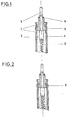
- an electric tubular heater has a jacket tube 1, in which there is a heating coil 3 embedded in insulating material 2 soaked in silicone oil.
- a connecting pin 4 is provided, which can be connected to an electrical power source, not shown.
- the connecting bolt 4 also has a part with a larger diameter and a part with a smaller diameter.
- the bolt part with a larger diameter is embedded in the insulating material 2 and electrically connected to the heating coil 3, while the subsequent bolt part with a small diameter runs a bit in the casing tube 1 and then protrudes from the tubular heating element for connection to a power source.
- the cross-sectional jump of the connecting bolt 4 is thus in one plane with the insulating material.
- an insulating bead 5 with a corresponding through hole is pushed in part over the small-diameter bolt part until the cross-sectional jump of the connecting bolt 4.
- the insulation bead 5, graduated in diameter has approximately the same outside diameter as the insulation material on the side facing the insulation material 2.
- a locking ring 6 is pushed onto the connecting pin 4 following the insulating bead.
- the connecting bolt 4 is pressed off when the insulating bead 5 is firmly pushed on in the vicinity of the securing ring 6.
- the locking ring 6 is pressed in the direction of the inside of the tubular heating element and thus the insulating bead is pressed against the insulating material.
- the connecting bolt 4 attains a certain strength with respect to the jacket tube 1
- the larger diameter part of the insulating bead 5 is pressed between two constrictions or pinches of the jacket tube. Since a mechanical holder 7 of the insulating bead is sufficient by using an insulating material 2 impregnated with silicone oil, any residual moisture in the jacket tube can escape to the outside at any time.
- Fig. 2 differs from the above only in that a triangular bead 8 is used instead of a round bead 5.
Landscapes
- Resistance Heating (AREA)
Description
- Die Erfindung betrifft einen Rohrheizkörper, bei dem in einem Mantelrohr aus verformbarem Metall in Isoliermaterial eine Heizwendel eingebettet ist, die an den Anschlußenden mit Anschlußbolzen verbunden ist, welche einen Bolzenteil mit einem größeren Durchmesser, der im Isoliermaterial eingebettet ist, und einen Bolzenteil mit einem geringeren Durchmesser, der durch eine in das Stirnende des Mantelrohres eingesetzte und durch das Mantelrohr mechanisch gehaltene Isolierperle hindurchgeführt ist, aufweisen.
- Es ist bei Rohrheizkörpern bekannt, die Isolierperlen mittels eines Klebers in die Innenwandung des Mantelrohrabschlusses einzukleben. Auf diese Weise wird verhindert, daß Feuchtigkeit in das Innere des Rohrheizkörpers gelangen kann und die Isolationswirkung des Isoliermaterials herabgesetzt wird.
- Dieser bekannte Rohrheizkörper weist jedoch den Nachteil auf, daß infolge der Verwendung eines Klebers nur eine beschränkte Temperaturbeständigkeit des Rohrheizkörpers gegeben ist.
- Es ist weiterhin eine Rohrheizkörperendenabdichtung bekannt, bei der die Abdichtung mittels einer temperaturbeständigen Glasur erfolgt. Bei einer derartigen Glasurabdichtung besteht jedoch die Gefahr, daß diese infolge großer Temperaturschwankungen reißt und demzufolge eine ungenügende Abdichtung gegenüber Feuchtigkeit darstellt.
- Andererseits kann bei beiden vorerwähnten Rohrheizkörperendenabdichtungen die Isolationswirkung durch eine im Rohrheizkörperinneren bei der Herstellung verbliebene Restfeuchtigkeit herabgesetzt sein, da die Restfeuchtigkeit durch den feuchtigkeitsdichten Abschluß nicht aus dem Rohrheizkörper entweichen kann.
- Hierzu ist es aus der DE-A-1 615 424 bekannt, zwischen dem Isoliermaterial, in welchem die Heizwendel eingebettet ist und dem am Anschlußende vorgesehenen Isolierpfropfen, durch den der Anschlußbolzen hindurchgeführt ist, eine viskose Dichtmasse vorzusehen, die bei Wärmebehandlung des Rohrheizkörpers ein Austreiben evtl. noch vorhandener Restfeuchtigkeit erlaubt und die dann gegen Ende der Wärmebehandlung eine zähflüssige oder gallertartige Konsistenz annimmt. Bei diesem bekannten Rohrheizkörper ist insofern eine zusätzliche Dichtmasse notwendig. Aus der DE-A-2 531 529 ist es zur Endenabdichtung eines elektrischen Rohrheizkörpers bekannt, unter Fortlassung einer derartigen zusätzlichen Dichtmasse, den für die Endenabdichtung vorgesehenen Isolierstoffpfropfen am stirnseitigen Ende des Mantelrohres einzupressen. Hierbei mag zwar eine mechanische Halterung des Isolierstoffpfropfens am Mantelrohr erzielt werden, jedoch ist die Halterung des Anschlußbolzens im Isolierstoffpfropfen nicht ausreichend, zumal zwischen dem Anschlußbolzen und der Innenbohrung des Isolierstoffpfropfens das Entweichen von Restfeuchtigkeit im Inneren des Rohrheizkörpers gewährleistet sein soll.
- Zur Befestigung des Anschlußbolzens in der Isolierperle sind relativ aufwendige Befestigungsmittel in Form von Schrauben aus der FR-A-803 095 und der US-A-2 046 102 bekannt, wobei zur mechanischen Befestigung der Isolierperle im Mantelrohr aus der US-PS 2 046 102 noch zusätzliche Haltemittel, die in umlaufende Nuten an der Innenwand des Mantelrohres eingreifen, vorgesehen sind. Auch die aus der FR-PS 803 095 bekannten, an der Mantelrohrinnenseite vorgesehenen Vorsprünge, welche in umlaufende Nuten der Isolierperle eingreifen, um diese mechanisch festzulegen, erschweren den Einbau der Isolierperle bei der Endenabdichtung des Rohrheizkörpers. Zudem werden dabei noch zusätzliche Dichtungsringe benötigt, um zwischen der Isolierperle und dem Mantelrohr eine ausreichende Abdichtung zu erzielen.
- Aufgabe der Erfindung ist es demgegenüber, einen Rohrheizkörper der eingangs genannten Art zu schaffen, bei dem trotz der Möglichkeit des Entweichens von im Mantelrohr befindlicher Restfeuchtigkeit eine mechanische Halterung der Isolierperle gegenüber dem Mantelrohr und eine mechanische Befestigung des Anschlußbolzens in der Isolierperle mit einfachen Mitteln, ohne zusätzliche Befestigungselemente, erreicht wird.
- Diese Aufgabe wird gelöst durch die Kombination der Merkmale, daß
- - die lsolierperle im Durchmesser abgestuft ausgebildet ist und der den größeren Durchmesser aufweisende Teil der Isolierperle zwischen zwei Einschnürungen bzw. Einquetschungen des Mantelrohres eingepreßt ist,
- - am aus der Isolierperle ragenden Teil des Anschlußbolzens eine Abdrückung vorgesehen ist durch die die Isolierperle in Richtung zur Rohrheizkörperinnenseite gepreßt ist,
- - das Isoliermaterial in bekannter Weise mit Silikonöl oder dergleichen getränkt ist.
- In vorteilhafter Weise kann zwischen die Abdrückung und die Isolierperle ein Sicherungsring gelegt sein.
- Die mit der Erfindung erzielbaren Vorteile bestehen insbesondere darin, daß der Rohrheizkörper einerseits infolge der mechanischen Halterung eine sehr hohe Temperaturbeständigkeit von etwa 600°C aufweist und andererseits keiner Beeinträchtigung seiner lsolationswirkung durch Feuchtigkeit mehr ausgesetzt ist. Zudem kommt hinzu, daß die Herstellung - da ja kein Einkleben bzw. Eingießen einer Endenabdichtung mehr erforderlich ist - äußerst einfach durchführbar ist.
- Die Erfindung wird im folgenden anhand der Zeichnungen näher erläutert. Es zeigt
- Fig. 1 ein Ausführungsbeispiel eines Rohrheizkörperendenabschlusses, wobei die Isolierperle einen runden Querschnitt aufweist und
- Fig. 2 das Ausführungsbeispiel gemäß Fig. 1, wobei jedoch die Isolierperle einen dreieckförmigen Querschnitt aufweist.
- Wie in Fig. 1 dargestellt, weist ein elektrischer Rohrheizkörper ein Mantelrohr 1 auf, in dem sich eine in Siliconöl durchtränktem Isoliermaterial 2 eingebettete Heizwendel 3 befindet. An dem Ende der Heizwendel 3 ist ein Anschlußbolzen 4 vorgesehen, der mit einer nicht gezeigten elektrischen Stromquelle verbunden werden kann. Der Anschlußbolzen 4 weist zudem einen Teil mit größerem Durchmesser und einen Teil mit kleinerem Durchmesser auf. Der Bolzenteil mit größerem Durchmesser ist im Isoliermaterial 2 eingebettet und mit der Heizwendel 3 elektrisch verbunden, während der sich anschließende Bolzenteil mit kleinem Durchmesser ein Stück im Mantelrohr 1 verläuft und anschließend aus dem Rohrheizkörper zur Verbindung mit einer Stromquelle herausragt. Der Querschnittsprung des Anschlußbolzens 4 liegt somit in einer Ebene mit dem Isoliermaterialabschluß.
- Um eine Isolierung des Anschlußbolzens 4 gegenüber dem Mantelrohr 2 zu gewährleisten, ist über dem Bolzenteil mit kleinem Durchmesser zum Teil eine Isolierperle 5 mit einem entsprechenden Durchgangsloch bis zum Querschnittsprung des Anschlußbolzens 4 aufgeschoben. Die im Durchmesser abgestufte Isolierperle 5 weist auf der dem Isoliermaterial 2 zugekehrten Seite etwa gleichen Außendurchmesser wie das Isoliermaterial auf. Weiterhin ist ein Sicherungsring 6 im Anschluß an die Isolierperle auf den Anschlußbolzen 4 aufgeschoben. Um ein Verschieben der Isolierperle 5 zu verhindern, ist bei fest aufgeschobener Isolierperle 5 in Nähe des Sicherungsringes 6 der Anschlußbolzen 4 abgedrückt. Demzufolge wird der Sicherungsring 6 in Richtung der Rohrheizkörperinnenseite und somit die Isolierperle gegen das Isoliermaterial gepreßt.
- Damit der Anschlußbolzen 4 insgesamt eine gewisse Festigkeit gegenüber dem Mantelrohr 1 erlangt, ist der einen größeren Durchmesser aufweisende Teil der Isolierperle 5 zwischen zwei Einschnürungen bzw. Einquetschungen des Mantelrohres eingepreßt. Da durch Verwendung eines siliconöldurchtränkten Isoliermaterials 2 eine mechanische Halterung 7 der Isolierperle ausreichend ist, kann jederzeit eine im Mantelrohr befindliche Restfeuchtigkeit nach außen entweichen.
- Das in Fig. 2 dargestellte Ausführungsbeispiel unterscheidet sich von dem obenerwähnten nur insoweit, daß anstelle einer Rundperle 5 eine Dreieckperle 8 Anwendung findet.
Claims (2)
Priority Applications (1)
| Application Number | Priority Date | Filing Date | Title |
|---|---|---|---|
| AT79103944T ATE82T1 (de) | 1978-10-13 | 1979-10-12 | Rohrheizkoerper. |
Applications Claiming Priority (2)
| Application Number | Priority Date | Filing Date | Title |
|---|---|---|---|
| DE19782844714 DE2844714A1 (de) | 1978-10-13 | 1978-10-13 | Endenabdichtung fuer einen elektrischen rohrheizkoerper |
| DE2844714 | 1978-10-13 |
Publications (2)
| Publication Number | Publication Date |
|---|---|
| EP0010275A1 EP0010275A1 (de) | 1980-04-30 |
| EP0010275B1 true EP0010275B1 (de) | 1981-06-10 |
Family
ID=6052145
Family Applications (1)
| Application Number | Title | Priority Date | Filing Date |
|---|---|---|---|
| EP79103944A Expired EP0010275B1 (de) | 1978-10-13 | 1979-10-12 | Rohrheizkörper |
Country Status (3)
| Country | Link |
|---|---|
| EP (1) | EP0010275B1 (de) |
| AT (1) | ATE82T1 (de) |
| DE (2) | DE2844714A1 (de) |
Families Citing this family (4)
| Publication number | Priority date | Publication date | Assignee | Title |
|---|---|---|---|---|
| DE3204875C2 (de) * | 1982-02-12 | 1985-02-07 | Elpag Ag Chur, Chur | Rohrheizkörper mit einer Überlastungssicherung |
| EP0157182B1 (de) * | 1984-03-01 | 1989-01-04 | Elpag Ag Chur | Rohrheizkörper |
| DE8910145U1 (de) * | 1989-08-24 | 1989-10-05 | Fritz Eichenauer GmbH & Co. KG Fabrik elektr. Spezialartikel, 6744 Kandel | Elektrischer Rohrheizkörperanschluß für zwei getrennte Heizleistungen |
| IT1294562B1 (it) * | 1997-02-07 | 1999-04-12 | I R C A Spa Ind Resistenze Cor | Procedimento di realizzazione di resistenze corazzate e resistenza ottenuta con il procedimento. |
Family Cites Families (5)
| Publication number | Priority date | Publication date | Assignee | Title |
|---|---|---|---|---|
| US2046102A (en) * | 1931-07-30 | 1936-06-30 | Gen Electric | Electric terminal connection |
| FR803095A (fr) * | 1935-09-20 | 1936-09-22 | Perfectionnements aux appareils électrothermiques | |
| DE1615424B2 (de) * | 1967-12-19 | 1973-02-15 | Siemens Electrogerate GmbH, 1000 Berlin u 8000 München | Elektrischer rohrheizkoerper |
| DE2410451A1 (de) * | 1974-03-05 | 1975-09-11 | Eichenauer Fa Fritz | Feuchtigkeitsdichter abschluss fuer elektrische rohrheizkoerper |
| DE2531529C2 (de) * | 1975-07-15 | 1985-05-02 | Stiebel Eltron Gmbh & Co Kg, 3450 Holzminden | Elektrischer Rohrheizkörper |
-
1978
- 1978-10-13 DE DE19782844714 patent/DE2844714A1/de not_active Withdrawn
- 1978-10-13 DE DE19787830574U patent/DE7830574U1/de not_active Expired
-
1979
- 1979-10-12 EP EP79103944A patent/EP0010275B1/de not_active Expired
- 1979-10-12 AT AT79103944T patent/ATE82T1/de not_active IP Right Cessation
Also Published As
| Publication number | Publication date |
|---|---|
| DE7830574U1 (de) | 1983-07-28 |
| ATE82T1 (de) | 1981-06-15 |
| EP0010275A1 (de) | 1980-04-30 |
| DE2844714A1 (de) | 1980-04-24 |
Similar Documents
| Publication | Publication Date | Title |
|---|---|---|
| DE19608675C2 (de) | Temperaturmeßvorrichtung mit einer medienführenden Rohrleitung | |
| DE3625999C2 (de) | ||
| DE102021109667A1 (de) | Steckverbinder mit Schraubverbindung | |
| DE2932638A1 (de) | Elektrische lampe mit einem huelsenfoermigen sockel | |
| DE19615375A1 (de) | Elektrischer Verbinder und Zündvorrichtung für eine Brennkraftmaschine | |
| DE3110660C2 (de) | Garnitur für das Ende eines Mittelspannnungs- oder Hochspannunskabels | |
| EP0762552A1 (de) | Endgehäuse für Steckverbinder | |
| DE3427207A1 (de) | Leiteranschlussvorrichtung an einem elektrischen patronenheizkoerper | |
| EP0010275B1 (de) | Rohrheizkörper | |
| DE2545179C3 (de) | Steckverbinder | |
| DE3137261C2 (de) | HF-dichter Rundsteckverbinder | |
| DE2937087C3 (de) | HF-Winkelstecker | |
| DD153720A5 (de) | Gluehkerze fuer verbrennungsmotoren | |
| DE1690679A1 (de) | Feuchtigkeitsdichter Anschluss fuer elektrische Heizpatronen | |
| DE69405432T2 (de) | Zündkerzenkappenvorrichtung für Verbrennungsmotor | |
| DE2745887A1 (de) | Elektrisches verbindergehaeuse | |
| DE2557031C3 (de) | Opferanode, insbesondere zur Verwendung bei einem Metalltank | |
| DE2622992B2 (de) | Elektrische Kupplung | |
| DE2653440A1 (de) | Apparateklemme | |
| DE3033211A1 (de) | Mehradrige elektrische leitung | |
| DE3531038A1 (de) | Stecker fuer ein koaxialkabel | |
| DE8017060U1 (de) | Elektrischer Stecker für eine feuchtigkeitsdichte Steckverbindung | |
| DE1048309B (de) | Stecker mit Beruehrungsschutz | |
| DE2637702A1 (de) | Elektrischer steckverbinder | |
| DE1065056B (de) | Kittlose Befestigung einer Huelse auf einem z. B. zylindrischen keramischen Koerper fuer die Einfuehrung von Leitungen in elektrische Geraete |
Legal Events
| Date | Code | Title | Description |
|---|---|---|---|
| PUAI | Public reference made under article 153(3) epc to a published international application that has entered the european phase |
Free format text: ORIGINAL CODE: 0009012 |
|
| AK | Designated contracting states |
Designated state(s): AT BE CH FR GB IT LU NL SE |
|
| 17P | Request for examination filed | ||
| ITF | It: translation for a ep patent filed | ||
| GRAA | (expected) grant |
Free format text: ORIGINAL CODE: 0009210 |
|
| AK | Designated contracting states |
Designated state(s): AT BE CH FR GB IT LU NL SE |
|
| REF | Corresponds to: |
Ref document number: 82 Country of ref document: AT Date of ref document: 19810615 Kind code of ref document: T |
|
| PGFP | Annual fee paid to national office [announced via postgrant information from national office to epo] |
Ref country code: LU Payment date: 19811001 Year of fee payment: 3 |
|
| PG25 | Lapsed in a contracting state [announced via postgrant information from national office to epo] |
Ref country code: LU Free format text: LAPSE BECAUSE OF NON-PAYMENT OF DUE FEES Effective date: 19811031 |
|
| PGFP | Annual fee paid to national office [announced via postgrant information from national office to epo] |
Ref country code: NL Payment date: 19811031 Year of fee payment: 3 |
|
| PLBI | Opposition filed |
Free format text: ORIGINAL CODE: 0009260 |
|
| 26 | Opposition filed |
Opponent name: SIEMENS AG, BERLIN UND MUENCHEN Effective date: 19820301 |
|
| PLAB | Opposition data, opponent's data or that of the opponent's representative modified |
Free format text: ORIGINAL CODE: 0009299OPPO |
|
| PLBI | Opposition filed |
Free format text: ORIGINAL CODE: 0009260 |
|
| 26 | Opposition filed |
Opponent name: STIEBEL ELTRON GMBH & CO.KG Effective date: 19820306 |
|
| R26 | Opposition filed (corrected) |
Opponent name: SIEMENS AG, BERLIN UND MUENCHEN Effective date: 19820301 |
|
| PG25 | Lapsed in a contracting state [announced via postgrant information from national office to epo] |
Ref country code: NL Effective date: 19830501 |
|
| NLV4 | Nl: lapsed or anulled due to non-payment of the annual fee | ||
| PLBN | Opposition rejected |
Free format text: ORIGINAL CODE: 0009273 |
|
| STAA | Information on the status of an ep patent application or granted ep patent |
Free format text: STATUS: OPPOSITION REJECTED |
|
| 27O | Opposition rejected |
Effective date: 19831204 |
|
| ITTA | It: last paid annual fee | ||
| EAL | Se: european patent in force in sweden |
Ref document number: 79103944.9 |
|
| PGFP | Annual fee paid to national office [announced via postgrant information from national office to epo] |
Ref country code: SE Payment date: 19951030 Year of fee payment: 17 |
|
| PGFP | Annual fee paid to national office [announced via postgrant information from national office to epo] |
Ref country code: FR Payment date: 19951031 Year of fee payment: 17 Ref country code: AT Payment date: 19951031 Year of fee payment: 17 |
|
| PGFP | Annual fee paid to national office [announced via postgrant information from national office to epo] |
Ref country code: CH Payment date: 19951102 Year of fee payment: 17 |
|
| PGFP | Annual fee paid to national office [announced via postgrant information from national office to epo] |
Ref country code: GB Payment date: 19951110 Year of fee payment: 17 |
|
| PGFP | Annual fee paid to national office [announced via postgrant information from national office to epo] |
Ref country code: BE Payment date: 19951130 Year of fee payment: 17 |
|
| PG25 | Lapsed in a contracting state [announced via postgrant information from national office to epo] |
Ref country code: GB Effective date: 19961012 Ref country code: AT Effective date: 19961012 |
|
| PG25 | Lapsed in a contracting state [announced via postgrant information from national office to epo] |
Ref country code: SE Effective date: 19961013 |
|
| PG25 | Lapsed in a contracting state [announced via postgrant information from national office to epo] |
Ref country code: CH Effective date: 19961031 Ref country code: BE Effective date: 19961031 |
|
| BERE | Be: lapsed |
Owner name: ELPAG A.G. CHUR Effective date: 19961031 |
|
| GBPC | Gb: european patent ceased through non-payment of renewal fee |
Effective date: 19961012 |
|
| REG | Reference to a national code |
Ref country code: CH Ref legal event code: PL |
|
| PG25 | Lapsed in a contracting state [announced via postgrant information from national office to epo] |
Ref country code: FR Effective date: 19970630 |
|
| EUG | Se: european patent has lapsed |
Ref document number: 79103944.9 |
|
| REG | Reference to a national code |
Ref country code: FR Ref legal event code: ST |