EP0008401B1 - Tür aus Kunststoff, insbesondere für Schienen- und Strassenfahrzeuge - Google Patents
Tür aus Kunststoff, insbesondere für Schienen- und Strassenfahrzeuge Download PDFInfo
- Publication number
- EP0008401B1 EP0008401B1 EP79102835A EP79102835A EP0008401B1 EP 0008401 B1 EP0008401 B1 EP 0008401B1 EP 79102835 A EP79102835 A EP 79102835A EP 79102835 A EP79102835 A EP 79102835A EP 0008401 B1 EP0008401 B1 EP 0008401B1
- Authority
- EP
- European Patent Office
- Prior art keywords
- door
- reinforcing frame
- rail
- elements
- encasement
- Prior art date
- Legal status (The legal status is an assumption and is not a legal conclusion. Google has not performed a legal analysis and makes no representation as to the accuracy of the status listed.)
- Expired
Links
Images

Classifications
-
- B—PERFORMING OPERATIONS; TRANSPORTING
- B60—VEHICLES IN GENERAL
- B60J—WINDOWS, WINDSCREENS, NON-FIXED ROOFS, DOORS, OR SIMILAR DEVICES FOR VEHICLES; REMOVABLE EXTERNAL PROTECTIVE COVERINGS SPECIALLY ADAPTED FOR VEHICLES
- B60J5/00—Doors
- B60J5/04—Doors arranged at the vehicle sides
- B60J5/048—Doors arranged at the vehicle sides characterised by the material
- B60J5/0481—Doors arranged at the vehicle sides characterised by the material plastic
-
- B—PERFORMING OPERATIONS; TRANSPORTING
- B60—VEHICLES IN GENERAL
- B60J—WINDOWS, WINDSCREENS, NON-FIXED ROOFS, DOORS, OR SIMILAR DEVICES FOR VEHICLES; REMOVABLE EXTERNAL PROTECTIVE COVERINGS SPECIALLY ADAPTED FOR VEHICLES
- B60J5/00—Doors
- B60J5/04—Doors arranged at the vehicle sides
- B60J5/048—Doors arranged at the vehicle sides characterised by the material
- B60J5/0484—Doors arranged at the vehicle sides characterised by the material hybrid, i.e. plastic moulded onto metal parts
-
- B—PERFORMING OPERATIONS; TRANSPORTING
- B60—VEHICLES IN GENERAL
- B60J—WINDOWS, WINDSCREENS, NON-FIXED ROOFS, DOORS, OR SIMILAR DEVICES FOR VEHICLES; REMOVABLE EXTERNAL PROTECTIVE COVERINGS SPECIALLY ADAPTED FOR VEHICLES
- B60J5/00—Doors
- B60J5/04—Doors arranged at the vehicle sides
- B60J5/0497—Doors arranged at the vehicle sides for load transporting vehicles or public transport, e.g. lorries, trucks, buses
-
- B—PERFORMING OPERATIONS; TRANSPORTING
- B61—RAILWAYS
- B61D—BODY DETAILS OR KINDS OF RAILWAY VEHICLES
- B61D19/00—Door arrangements specially adapted for rail vehicles
- B61D19/02—Door arrangements specially adapted for rail vehicles for carriages
-
- B—PERFORMING OPERATIONS; TRANSPORTING
- B62—LAND VEHICLES FOR TRAVELLING OTHERWISE THAN ON RAILS
- B62D—MOTOR VEHICLES; TRAILERS
- B62D29/00—Superstructures, understructures, or sub-units thereof, characterised by the material thereof
- B62D29/001—Superstructures, understructures, or sub-units thereof, characterised by the material thereof characterised by combining metal and synthetic material
-
- E—FIXED CONSTRUCTIONS
- E06—DOORS, WINDOWS, SHUTTERS, OR ROLLER BLINDS IN GENERAL; LADDERS
- E06B—FIXED OR MOVABLE CLOSURES FOR OPENINGS IN BUILDINGS, VEHICLES, FENCES OR LIKE ENCLOSURES IN GENERAL, e.g. DOORS, WINDOWS, BLINDS, GATES
- E06B3/00—Window sashes, door leaves, or like elements for closing wall or like openings; Layout of fixed or moving closures, e.g. windows in wall or like openings; Features of rigidly-mounted outer frames relating to the mounting of wing frames
- E06B3/04—Wing frames not characterised by the manner of movement
- E06B3/06—Single frames
- E06B3/08—Constructions depending on the use of specified materials
- E06B3/20—Constructions depending on the use of specified materials of plastics
- E06B3/205—Constructions depending on the use of specified materials of plastics moulded or extruded around a core
-
- E—FIXED CONSTRUCTIONS
- E06—DOORS, WINDOWS, SHUTTERS, OR ROLLER BLINDS IN GENERAL; LADDERS
- E06B—FIXED OR MOVABLE CLOSURES FOR OPENINGS IN BUILDINGS, VEHICLES, FENCES OR LIKE ENCLOSURES IN GENERAL, e.g. DOORS, WINDOWS, BLINDS, GATES
- E06B3/00—Window sashes, door leaves, or like elements for closing wall or like openings; Layout of fixed or moving closures, e.g. windows in wall or like openings; Features of rigidly-mounted outer frames relating to the mounting of wing frames
- E06B3/70—Door leaves
- E06B3/72—Door leaves consisting of frame and panels, e.g. of raised panel type
- E06B3/725—Door leaves consisting of frame and panels, e.g. of raised panel type with separate hollow frames, e.g. foam-filled
-
- E—FIXED CONSTRUCTIONS
- E06—DOORS, WINDOWS, SHUTTERS, OR ROLLER BLINDS IN GENERAL; LADDERS
- E06B—FIXED OR MOVABLE CLOSURES FOR OPENINGS IN BUILDINGS, VEHICLES, FENCES OR LIKE ENCLOSURES IN GENERAL, e.g. DOORS, WINDOWS, BLINDS, GATES
- E06B3/00—Window sashes, door leaves, or like elements for closing wall or like openings; Layout of fixed or moving closures, e.g. windows in wall or like openings; Features of rigidly-mounted outer frames relating to the mounting of wing frames
- E06B3/70—Door leaves
- E06B2003/7059—Specific frame characteristics
- E06B2003/7082—Plastic frames
- E06B2003/7084—Plastic frames reinforced with metal or wood sections
-
- E—FIXED CONSTRUCTIONS
- E06—DOORS, WINDOWS, SHUTTERS, OR ROLLER BLINDS IN GENERAL; LADDERS
- E06B—FIXED OR MOVABLE CLOSURES FOR OPENINGS IN BUILDINGS, VEHICLES, FENCES OR LIKE ENCLOSURES IN GENERAL, e.g. DOORS, WINDOWS, BLINDS, GATES
- E06B3/00—Window sashes, door leaves, or like elements for closing wall or like openings; Layout of fixed or moving closures, e.g. windows in wall or like openings; Features of rigidly-mounted outer frames relating to the mounting of wing frames
- E06B3/70—Door leaves
- E06B2003/7059—Specific frame characteristics
- E06B2003/7092—Specific frame characteristics with frame members not directly or resiliently connected to each other
Definitions
- the invention relates to a door made of plastic, in particular for rail and road vehicles, which has a reinforcement frame arranged in the region of its edges and consisting of metallic profiles and a frame which includes this frame and is made of foamed plastic and forms the sheet of the door and all the necessary recesses for windows , Handles, etc. containing casing.
- a smooth outer part and a shell-shaped inner part made of glass fiber reinforced plastic (GRP) in the case of folding doors, these parts being produced individually in the pressing process and connected to one another by adhesive bonding.
- GRP glass fiber reinforced plastic
- a metallic, hollow beam-like reinforcement profile is preferably arranged in the region of the vertical outer door handle of a door leaf, which is glued to the GRP door parts and the length of which, depending on whether two or only one in a door leaf Window cutout is provided, extends approximately over the length of the entire or half of the door leaf.
- Metallic crossbars are connected to such a reinforcement profile and extend across the width of the door leaf and are also connected by gluing (DE-A-1 780 307).
- doors of this previously known construction are characterized by low weight and great rigidity, the relatively great effort in their manufacture is regarded as a defect; This effort is, again summarized below, determined by the production steps - pressing the smooth and shell-shaped GRP door parts with the appropriate tool, stiffening with profiles to be protected against corrosion beforehand, gluing, edge trimming, grinding and foaming in another tool.
- a door for vehicles according to the preamble of claim 1 is known (DE-A-1 655 656), the door leaf of which is made of foamed plastic and encapsulates metallic reinforcement profiles. These profiles limit a window cutout and a window guide shaft provided in the door leaf; this means that the profiles only provide local stabilization for the door leaf.
- the object of the invention is to improve the rigidity of a door of the generic type, stresses resulting from mechanical and thermal loads being avoided in view of the different materials of the door - metal and plastic.
- This object is achieved in that two adjacent elements of the all-round reinforcement frame are slidably connected to each other in the sense of an expansion compensation.
- the reinforcement frame has four elements each formed from a rectangular tube, at the ends of which are arranged displaceably engaged mounts.
- brackets consist of fittings fitted at right angles to one another at the ends of the two lateral elements and each at the ends of the upper and lower elements of the reinforcing frame Correspondingly arranged recordings for the adapters exist.
- the reinforcing frame is provided with all the fastening chucks required for attachments such as door bearings, handles, etc.
- the reinforcing frame has a guide rail with a U-shaped cross-section at the bottom, this rail being covered on its outer surfaces by the casing. This covering of the rail advantageously results in a uniform, optically acceptable appearance of the door.
- a last embodiment of the invention provides that the area of the sheathing lying below the window opening is one contains foam-permeable, preferably metallic insert.
- the door leaf has a particularly high rigidity due to the circumferential reinforcement frame and thus meets the requirements, particularly in railway operations, for example for a long, maintenance-free service life.
- the expansion compensation created by means of the displaceable connection of the elements of the reinforcement frame contributes to this service life, which, in the event of mechanical and thermal loads on the door, reliably prevents the occurrence of stresses which are particularly critical for its plastic door leaf.
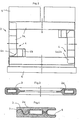
- the door 1 consists essentially of the reinforcement frame 2 and the casing made of foamed plastic 3. This closes according to FIGS. 1, 3 and 4. the reinforcement frame 2 and welded parts thereon, upper. Fastening chuck 5, lower guide rail 6, and forms the rest of the sheet of the door 1.
- the casing 3 in the upper part of the door 1 has a recess for a window; in the lower, windowless part of the door 1, the casing 3 contains the foam-permeable insert 7, for example an expanded metal grid.
- the reinforcement frame 2 is formed from four elements 2a, here rectangular tubes, which are connected via brackets 4 attached to their ends.
Landscapes
- Engineering & Computer Science (AREA)
- Mechanical Engineering (AREA)
- Structural Engineering (AREA)
- Civil Engineering (AREA)
- Architecture (AREA)
- Chemical & Material Sciences (AREA)
- Combustion & Propulsion (AREA)
- Transportation (AREA)
- Window Of Vehicle (AREA)
- Vehicle Interior And Exterior Ornaments, Soundproofing, And Insulation (AREA)
- Body Structure For Vehicles (AREA)
Description
- Die Erfindung betrifft eine Tür aus Kunststoff, insbesondere für Schienen- und Straßenfahrzeuge, die einen im Bereich ihrer Kanten angeordneten, aus metallischen Profilen bestehenden Verstärkungsrahmen und eine diesen Rahmen einschließende, aus geschäumtem Kunststoff erstellte, das Blatt der Tür bildende und alle erforderlichen Ausnehmungen für Fenster, Handgriffe usw. enthaltende Ummantelung aufweist.
- Es ist bekannt, bei Falttüren ein glattes Außenteil und ein schalenförmiges Innenteil aus glasfaserverstärktem Kunststoff (GFK) zu verwenden, wobei diese Teile einzeln im Preßverfahren erstellt und miteinander durch Kleben verbunden sind. In dem zwischen Innen- und Außenteil gebildeten Hohlraum ist im Bereich des senkrechten äußeren Türholmens eines Türblattes vorzugsweise ein metallisches, hohlträgerartiges Verstärkungsprofil angeordnet, das mit den GFK-Türteilen verklebt ist und dessen Länge sich, je nachdem, ob in einem Türblatt zwei oder nur ein Fensterausschnitt vorgesehen ist, etwa über die Länge des ganzen bzw. halben Türblattes erstreckt. An ein derartiges Verstärkungsprofil sind metallische Querstege angeschlossen, die sich über die Breite des Türblattes erstrecken und damit gleichfalls durch Kleben verbunden sind (DE-A-1 780 307). Darüber hinaus ist es üblich, in den Hohlraum derartiger Türen außer solchen Verstärkungsprofilen noch Schaumstoff zur Aussteifung einzubringen. Wenngleich sich Türen nach dieser vorbekannten Bauweise durch geringes Gewicht und große Steifigkeit auszeichnen, wird als Mangel der verhältnismäßig große Aufwand bei ihrer Fertigung angesehen; dieser Aufwand ist, im weiteren nochmals zusammenfassend dargestellt, durch die Fertigungsschritte - Pressen der glatten und schalenförmigen GFK-Türteile mit jeweils entsprechendem Werkzeug, Aussteifen mit vorher gegen Korrosion zu schützenden Profilen, Verkleben, Kantenbeschneiden, Schleifen und Ausschäumen in einem weiteren Werkzeug - bestimmt. Weiter ist eine Tür für Fahrzeuge gemäß dem Oberbegriff des Patentanspruchs 1 bekannt (DE-A-1 655 656), deren aus geschäumtem Kunststoff erstelltes Türblatt metallische Verstärkungsprofile ummantelt. Diese Profile begrenzen einen im Türblatt vorgesehenen Fensterausschnitt und einen Fensterführungsschacht; dadurch erbringen die Profile eine nur örtliche Stabilisierung für das Türblatt.
- Der Erfindung liegt die Aufgabe zugrunde, eine Tür der gattungsgemäßen Art in ihrer Steifigkeit zu verbessern, wobei im Hinblick auf die unterschiedlichen Werkstoffe der Tür - Metall und Kunststoff - aus mechanischen und thermischen Belastungen resultierende Spannungen vermieden werden sollen.
- Diese Aufgabe wird erfindungsgemäß dadurch gelöst, daß je zwei benachbarte Elamente des umlaufend ausgebildeten Verstärkungsrahmens im Sinne eines Dehnungsausgleiches verschiebbar miteinander verbunden sind.
- In zweckmäßiger Weiterbildung der Erfindung ist vorgesehen, daß der Verstärkungsrahmen vier jeweils aus einem Rechteckrohr gebildete Elemente aufweist, an deren Enden miteinander verschiebbar in Eingriff stehende Halterungen angeordnet sind.
- Der verschiebbare Eingriff der Halterungen wird in einfacher Weise nach einer ergänzenden Ausführungsform der Erfindung dadurch erreicht, daß die Halterungen aus jeweils an den Enden der beiden seitlichen Elemente im rechten Winkel zueinander angebrachten Paßstücken und aus jeweils an den Enden des oberen und des unteren Elementes des Verstärkungsrahmens entsprechend angeordneten Aufnahmen für die Paßstücke bestehen.
- Die Fertigausrüstung der Tür ist mit geringerem Arbeitsaufwand nach einer nächsten Ausbildung der Erfindung dadurch möglich, daß der Verstärkungsrahmen mit allen für Anbauteile wie Türlager, Handgriffe usw. erforderlichen Befestigungsfuttern versehen ist.
- Für den Einsatz der Tür als Schiebetür ist in Weiterbildung der Erfindung vorgesehen, daß der Verstärkungsrahmen unten eine Führungsschiene mit U-förmigem Querschnitt aufweist, wobei diese Schiene auf ihren Außenflächen von der Ummantelung bedeckt ist. Durch diese Bedeckung der Schiene ergibt sich vorteilhaft ein einheitliches, optisch geiälliges Aussehen derTür.
- Um bei einer nur im oberen Bereich mit einem Fenster ausgerüsteten Tür den unteren, fensterlosen Bereich der Ummantelung festigkeitsmäßig noch günstiger zu gestalten und auch gegen mutwillige Beschädigungen zu schützen, sieht eine letzte Ausbildung der Erfindung vor, daß der unterhalb der Fensteröffnung liegende Bereich der Ummantelung eine schaumdurchlässige, vorzugsweise metallische Einlage enthält.
- Die mit der Erfindung erzielbaren Vorteile bestehen insbesondere darin, daß das Türblatt durch den umlaufenden Verstärkungsrahmen eine besonders hohe Steifigkeit aufweist und damit den vor allem im Eisenbahnbetrieb gestellten Forderungen, beispielsweise nach möglichst langer wartungsfreier Standzeit, genügt. Zu dieser Standzeit trägt der über die verschiebbare Verbindung der Elemente des Verstärkungsrahmens geschaffene Dehnungsausgleich bei, der bei mechanischen und thermischen Belastungen der Tür ein Entstehen von insbesondere für deren Kunststoff-Türblatt kritischen Spannungen sicher verhindert.
- Ein Ausführungsbeispiel der Erfindung, ausgeführt für eine Schiebetür, ist in der Zeichnung dargestellt und wird im folgenden näher beschrieben. Es zeigt
- Fig. 1 die Tür in Ansicht mit einem Teilausschnitt,
- Fig. 2 einen Verstärkungsrahmen in Ansicht, in gegenüber der Darstellung nach Fig. 1 vergrößertem Maßstab,
- Fig. 3 den Schnitt nach der Linie III-III in Fig: 1, in vergrößertem Maßstab,
- Fig. 4 den Schnitt nach der Linie IV-IV in Fig. 1, um 90° gedreht, in vergrößertem Maßstab.
- Nach den Fig. 1 bis 4 besteht die Tür 1 im wesentlichen aus dem Verstärkungsrahmen 2 und der aus geschäumtem Kunststoff erstellten Ummantelung 3. Diese schließt nach den Fig. 1, 3 und 4. den Verstärkungsrahmen 2 und daran befindliche Anschweißteile, obere . Befestigungsfutter 5, untere Führungsschiene 6, ein und bildet im übrigen das Blatt der Tür 1. Gemäß Fig. 1 weist die Ummantelung 3 im oberen Teil der Tür 1 eine Ausnehmung für ein Fenster auf; in dem unteren, fensterlosen Teil der Tür 1 enthält die Ummantelung 3 die schaumdurchlässige Einlage 7, beispielsweise ein Streckmetallgitter. Nach Fig. 2 ist der Verstärkungsrahmen 2 aus vier Elementen 2a, hier Rechteckrohre, gebildet, die über an ihren Enden angebrachte Halterungen 4 verbunden sind. Diese bestehen aus rechtwinklig zueinander an den seitlichen Elementen 2a angeschweißten Paßstücken 4a, die verschiebbar in an dem oberen und unteren Element 2a angeordnete Aufnahmen 4b eingreifen. Diese Aufnahmen sind durch Ausnehmungen und angeschweißte Rechteckrohrstücke gebildet..
Claims (6)
Priority Applications (1)
| Application Number | Priority Date | Filing Date | Title |
|---|---|---|---|
| AT79102835T ATE622T1 (de) | 1978-08-21 | 1979-08-07 | Tuer aus kunststoff, insbesondere fuer schienenund strassenfahrzeuge. |
Applications Claiming Priority (2)
| Application Number | Priority Date | Filing Date | Title |
|---|---|---|---|
| DE2836491 | 1978-08-21 | ||
| DE2836491 | 1978-08-21 |
Publications (2)
| Publication Number | Publication Date |
|---|---|
| EP0008401A1 EP0008401A1 (de) | 1980-03-05 |
| EP0008401B1 true EP0008401B1 (de) | 1982-01-27 |
Family
ID=6047534
Family Applications (1)
| Application Number | Title | Priority Date | Filing Date |
|---|---|---|---|
| EP79102835A Expired EP0008401B1 (de) | 1978-08-21 | 1979-08-07 | Tür aus Kunststoff, insbesondere für Schienen- und Strassenfahrzeuge |
Country Status (3)
| Country | Link |
|---|---|
| EP (1) | EP0008401B1 (de) |
| AT (1) | ATE622T1 (de) |
| DE (1) | DE2961974D1 (de) |
Cited By (1)
| Publication number | Priority date | Publication date | Assignee | Title |
|---|---|---|---|---|
| RU208544U1 (ru) * | 2018-02-06 | 2021-12-23 | Сименс Мобилити Гмбх | Дверь рельсового транспортного средства |
Families Citing this family (1)
| Publication number | Priority date | Publication date | Assignee | Title |
|---|---|---|---|---|
| AT501745B1 (de) * | 2005-08-01 | 2006-11-15 | Knorr Bremse Gmbh | Türblatt |
Family Cites Families (5)
| Publication number | Priority date | Publication date | Assignee | Title |
|---|---|---|---|---|
| NL6708959A (de) * | 1967-06-27 | 1968-12-30 | ||
| DE1902878A1 (de) * | 1967-11-04 | 1970-11-12 | Polymatic Patentverwertungsgmb | Verfahren zum Herstellen einstueckiger,mit glasfaserverstaerktem Giessharz ummantelter Formkoerper |
| DE1655656A1 (de) * | 1968-01-05 | 1971-08-12 | Volkswagenwerk Ag | Kraftfahrzeugtuer aus Kunststoff |
| DE1909753A1 (de) * | 1969-02-27 | 1971-04-01 | Didier Werke Ag | Verfahren zum Herstellen von einstueckigen,mit glasfaserverstaerktem Giessharz ummantelten Koerpern,vor allem Koerpern hoher Festigkeit,z.B. Bauteilen,insbesondere in sich geschlossenen Fenster-und Tuerrahmen |
| FR2129225A5 (de) * | 1971-03-19 | 1972-10-27 | Patin Pierre |
-
1979
- 1979-08-07 AT AT79102835T patent/ATE622T1/de not_active IP Right Cessation
- 1979-08-07 DE DE7979102835T patent/DE2961974D1/de not_active Expired
- 1979-08-07 EP EP79102835A patent/EP0008401B1/de not_active Expired
Cited By (2)
| Publication number | Priority date | Publication date | Assignee | Title |
|---|---|---|---|---|
| RU208544U1 (ru) * | 2018-02-06 | 2021-12-23 | Сименс Мобилити Гмбх | Дверь рельсового транспортного средства |
| EP3727988B1 (de) * | 2018-02-06 | 2022-01-26 | Siemens Mobility GmbH | Schienenfahrzeugtür |
Also Published As
| Publication number | Publication date |
|---|---|
| DE2961974D1 (en) | 1982-03-11 |
| EP0008401A1 (de) | 1980-03-05 |
| ATE622T1 (de) | 1982-02-15 |
Similar Documents
| Publication | Publication Date | Title |
|---|---|---|
| DE2715550C3 (de) | Aufbau für Omnibusse | |
| DE102012023653A1 (de) | Kraftfahrzeugkarosserie mit Leichtbauteil | |
| DE1480089A1 (de) | Tuer von zusammengesetztem Aufbau,insbesondere fuer Kraftfahrzeuge | |
| EP2935739B1 (de) | Abdeckvorrichtung für ein mit einem schliesskeilmodul in eine die verbindung einer fahrzeugtüre mit einem seitenwandrahmen einer fahrzeugkarosserie bewirkende lösbare kopplung bringbares haltebackenmodul | |
| DE4427402A1 (de) | Konstruktionselement aus einer Glasscheibe und einem mit der Glasscheibe verklebten Holm oder Rahmen | |
| DE3641242A1 (de) | Fahrzeugtuer | |
| EP0152110A2 (de) | Randschiene für eine Scheibe, insbesondere einer Ganzglastüre | |
| DE8309452U1 (de) | Tür eines Motorfahrzeuges | |
| DE3732086C2 (de) | ||
| EP0009246A1 (de) | Personenfahrzeug mit eingeklebten Fensterscheiben | |
| DE19727010B4 (de) | Fensterrahmenmodul zur Herstellung von Kraftfahrzeugtüren | |
| EP0457188B1 (de) | Verfahren zur Fixierung eines Fensterführungsprofiles und entsprechende Anordnung | |
| DE19832076A1 (de) | Versteifung für einen Türbereich eines Kraftfahrzeugaufbaues | |
| EP0102526A2 (de) | Fahrzeugfenster, insbesondere Seitenfenster von Reisezugwagen | |
| EP0354325A2 (de) | Bausatz zum Umbau eines Kraftfahrzeuges mit Stahldach in ein Cabriolet | |
| DE3446734A1 (de) | Kastenkonstruktion, insbesondere fuer nutzfahrzeuge wie brandschutzfahrzeuge | |
| DE3241652A1 (de) | Fahrzeugaufbau mit fenster | |
| DE2935230C2 (de) | Karosserie-Wandteil, insbesondere Heckklappe | |
| EP0008401A1 (de) | Tür aus Kunststoff, insbesondere für Schienen- und Strassenfahrzeuge | |
| DE69200682T2 (de) | Beglasung, insbesondere für Strassen oder Schienenfahrzeugfenster. | |
| DE3930419A1 (de) | Rolltor fuer wechselaufbauten von fahrzeugen und paneel fuer derartige tore | |
| EP0313672B1 (de) | Randschiene für eine Scheibe, insbesondere einer Ganzglastüre | |
| DE10041187A1 (de) | Tür für Kraftfahrzeuge | |
| EP0152045A1 (de) | Fahrbare Arbeitsmaschine mit einem Aufbau | |
| DE7824874U1 (de) | Tuer aus kunststoff, insbesondere fuer schienen- und strassenfahrzeuge |
Legal Events
| Date | Code | Title | Description |
|---|---|---|---|
| PUAI | Public reference made under article 153(3) epc to a published international application that has entered the european phase |
Free format text: ORIGINAL CODE: 0009012 |
|
| AK | Designated contracting states |
Designated state(s): AT BE CH DE FR GB IT NL |
|
| ITCL | It: translation for ep claims filed |
Representative=s name: SOCIETA' ITALIANA BREVETTI S.P.A. |
|
| 17P | Request for examination filed | ||
| GRAA | (expected) grant |
Free format text: ORIGINAL CODE: 0009210 |
|
| AK | Designated contracting states |
Designated state(s): AT BE CH DE FR GB IT NL |
|
| PG25 | Lapsed in a contracting state [announced via postgrant information from national office to epo] |
Ref country code: IT Free format text: LAPSE BECAUSE OF FAILURE TO SUBMIT A TRANSLATION OF THE DESCRIPTION OR TO PAY THE FEE WITHIN THE PRESCRIBED TIME-LIMIT;WARNING: LAPSES OF ITALIAN PATENTS WITH EFFECTIVE DATE BEFORE 2007 MAY HAVE OCCURRED AT ANY TIME BEFORE 2007. THE CORRECT EFFECTIVE DATE MAY BE DIFFERENT FROM THE ONE RECORDED. Effective date: 19820127 Ref country code: FR Free format text: THE PATENT HAS BEEN ANNULLED BY A DECISION OF A NATIONAL AUTHORITY Effective date: 19820127 Ref country code: BE Effective date: 19820127 |
|
| REF | Corresponds to: |
Ref document number: 622 Country of ref document: AT Date of ref document: 19820215 Kind code of ref document: T |
|
| REF | Corresponds to: |
Ref document number: 2961974 Country of ref document: DE Date of ref document: 19820311 |
|
| PG25 | Lapsed in a contracting state [announced via postgrant information from national office to epo] |
Ref country code: CH Effective date: 19820831 |
|
| REG | Reference to a national code |
Ref country code: CH Ref legal event code: PL |
|
| GBPC | Gb: european patent ceased through non-payment of renewal fee | ||
| PGFP | Annual fee paid to national office [announced via postgrant information from national office to epo] |
Ref country code: DE Payment date: 19840802 Year of fee payment: 6 |
|
| PGFP | Annual fee paid to national office [announced via postgrant information from national office to epo] |
Ref country code: AT Payment date: 19850830 Year of fee payment: 7 |
|
| PGFP | Annual fee paid to national office [announced via postgrant information from national office to epo] |
Ref country code: NL Payment date: 19850831 Year of fee payment: 7 |
|
| PG25 | Lapsed in a contracting state [announced via postgrant information from national office to epo] |
Ref country code: AT Effective date: 19860807 |
|
| PG25 | Lapsed in a contracting state [announced via postgrant information from national office to epo] |
Ref country code: NL Effective date: 19870301 |
|
| NLV4 | Nl: lapsed or anulled due to non-payment of the annual fee | ||
| PG25 | Lapsed in a contracting state [announced via postgrant information from national office to epo] |
Ref country code: DE Effective date: 19870501 |
|
| PG25 | Lapsed in a contracting state [announced via postgrant information from national office to epo] |
Ref country code: GB Effective date: 19881118 |
|
| PLBE | No opposition filed within time limit |
Free format text: ORIGINAL CODE: 0009261 |
|
| STAA | Information on the status of an ep patent application or granted ep patent |
Free format text: STATUS: NO OPPOSITION FILED WITHIN TIME LIMIT |