EP0008376B2 - Verfahren zum Stranggiessen von Metall in eine Kokille und Einwirkung eines elektromagnetischen Feldes - Google Patents
Verfahren zum Stranggiessen von Metall in eine Kokille und Einwirkung eines elektromagnetischen Feldes Download PDFInfo
- Publication number
- EP0008376B2 EP0008376B2 EP19790102611 EP79102611A EP0008376B2 EP 0008376 B2 EP0008376 B2 EP 0008376B2 EP 19790102611 EP19790102611 EP 19790102611 EP 79102611 A EP79102611 A EP 79102611A EP 0008376 B2 EP0008376 B2 EP 0008376B2
- Authority
- EP
- European Patent Office
- Prior art keywords
- strand
- thrust
- molten metal
- phases
- acting
- Prior art date
- Legal status (The legal status is an assumption and is not a legal conclusion. Google has not performed a legal analysis and makes no representation as to the accuracy of the status listed.)
- Expired
Links
- 238000000034 method Methods 0.000 title claims description 28
- 239000002184 metal Substances 0.000 title claims description 13
- 229910052751 metal Inorganic materials 0.000 title claims description 13
- 230000005672 electromagnetic field Effects 0.000 title claims description 5
- 238000005266 casting Methods 0.000 title description 14
- 238000003756 stirring Methods 0.000 claims description 17
- 238000009749 continuous casting Methods 0.000 claims description 7
- 238000004804 winding Methods 0.000 claims description 7
- 230000001939 inductive effect Effects 0.000 claims description 3
- 239000007788 liquid Substances 0.000 description 18
- 239000000155 melt Substances 0.000 description 13
- 239000013078 crystal Substances 0.000 description 11
- 238000005204 segregation Methods 0.000 description 11
- 238000001000 micrograph Methods 0.000 description 9
- 229910052717 sulfur Inorganic materials 0.000 description 9
- 229910000831 Steel Inorganic materials 0.000 description 8
- 230000000694 effects Effects 0.000 description 8
- 239000010959 steel Substances 0.000 description 8
- NINIDFKCEFEMDL-UHFFFAOYSA-N Sulfur Chemical compound [S] NINIDFKCEFEMDL-UHFFFAOYSA-N 0.000 description 7
- 238000001816 cooling Methods 0.000 description 7
- 239000011593 sulfur Substances 0.000 description 7
- 230000009471 action Effects 0.000 description 3
- 210000001787 dendrite Anatomy 0.000 description 3
- 238000009826 distribution Methods 0.000 description 3
- 230000006872 improvement Effects 0.000 description 3
- 239000000463 material Substances 0.000 description 3
- 230000008569 process Effects 0.000 description 3
- 229910045601 alloy Inorganic materials 0.000 description 2
- 239000000956 alloy Substances 0.000 description 2
- 239000000498 cooling water Substances 0.000 description 2
- 238000004445 quantitative analysis Methods 0.000 description 2
- 238000007711 solidification Methods 0.000 description 2
- 230000008023 solidification Effects 0.000 description 2
- RYGMFSIKBFXOCR-UHFFFAOYSA-N Copper Chemical compound [Cu] RYGMFSIKBFXOCR-UHFFFAOYSA-N 0.000 description 1
- 229910001208 Crucible steel Inorganic materials 0.000 description 1
- 241000255969 Pieris brassicae Species 0.000 description 1
- 230000003321 amplification Effects 0.000 description 1
- 238000004458 analytical method Methods 0.000 description 1
- 230000015572 biosynthetic process Effects 0.000 description 1
- 230000008859 change Effects 0.000 description 1
- 238000010276 construction Methods 0.000 description 1
- 229910052802 copper Inorganic materials 0.000 description 1
- 239000010949 copper Substances 0.000 description 1
- 230000001419 dependent effect Effects 0.000 description 1
- 238000010586 diagram Methods 0.000 description 1
- 230000005611 electricity Effects 0.000 description 1
- 230000005284 excitation Effects 0.000 description 1
- 238000002474 experimental method Methods 0.000 description 1
- -1 ferrous metals Chemical class 0.000 description 1
- 230000004907 flux Effects 0.000 description 1
- 230000003993 interaction Effects 0.000 description 1
- 239000000696 magnetic material Substances 0.000 description 1
- 238000003760 magnetic stirring Methods 0.000 description 1
- 238000002844 melting Methods 0.000 description 1
- 230000008018 melting Effects 0.000 description 1
- 238000002156 mixing Methods 0.000 description 1
- 239000000203 mixture Substances 0.000 description 1
- 238000003199 nucleic acid amplification method Methods 0.000 description 1
- 230000035515 penetration Effects 0.000 description 1
- 238000005293 physical law Methods 0.000 description 1
- 230000009467 reduction Effects 0.000 description 1
- 238000004062 sedimentation Methods 0.000 description 1
- IHQKEDIOMGYHEB-UHFFFAOYSA-M sodium dimethylarsinate Chemical class [Na+].C[As](C)([O-])=O IHQKEDIOMGYHEB-UHFFFAOYSA-M 0.000 description 1
- 239000007921 spray Substances 0.000 description 1
- 239000010935 stainless steel Substances 0.000 description 1
- 229910001220 stainless steel Inorganic materials 0.000 description 1
- 238000009827 uniform distribution Methods 0.000 description 1
Images


Classifications
-
- B—PERFORMING OPERATIONS; TRANSPORTING
- B22—CASTING; POWDER METALLURGY
- B22D—CASTING OF METALS; CASTING OF OTHER SUBSTANCES BY THE SAME PROCESSES OR DEVICES
- B22D11/00—Continuous casting of metals, i.e. casting in indefinite lengths
- B22D11/12—Accessories for subsequent treating or working cast stock in situ
- B22D11/122—Accessories for subsequent treating or working cast stock in situ using magnetic fields
Definitions
- the present invention relates to a method for the continuous casting of metal, according to the preamble of claim 1 and claim 2.
- the structure of a strand produced by the continuous casting process depends, among other things, on the composition of the material and the casting temperature. At casting temperatures of only a few degrees Celsius above the melting temperature, a globular, non-directional structure, and at casting temperatures with more than 15 ° above liquidus, a columnar, directed structure with a strong, central positive segregation of the accompanying elements. In practice, for casting reasons, casting must be carried out at excess temperatures of more than 20 ° C. For this reason, many efforts have already been made to obtain a slab with a predominantly globulitic, undirected structure and little central segregation even with continuous casting at such excess temperatures.
- Alloy and accompanying elements such as C, Si, Mn, P, S etc. are contained in the steel, which can lead to segregation, especially central segregation, when solidified.
- segregations, as well as the crystal structure are known u. a. depending on the level of excess temperature.
- segregations are to be prevented by electromagnetic stirring or by the turbulent flow generated.
- the solidification structure should be influenced in such a way that the largest possible zone of dense, undirected crystal structure is obtained.
- the solidification front is influenced by the strong local movement of the melt in such a way that so-called white bands form. These white bands are negative segregations that can have a negative impact on quality.
- a device in which an electromagnetic device with three pole pairs is arranged around the mold tube, which sets the liquid core into a movement rotating about the longitudinal axis of the strand.
- This rotation created by a perfect rotating field, has an insufficient turbulence in its flow.
- the mixing of the liquid steel is imperfect because there is no force acting across the strand due to the uniform magnetic application of the melt.
- This relatively low turbulence leaves something to be desired in terms of the quality of the cast product in relation to the surface, the distribution of the alloy and accompanying elements, but also to the internal structure.
- thrust forces are generated in the direction of the longitudinal axis of the strand with an electromagnetic traveling field, the magnets running around the strand being arranged between the pairs of rollers up to the end of the sump.
- the flow created along the swamp brings the desired area of non-columnar structure and prevents the occurrence of significant segregations, in particular mid-sedimentation and white bands.
- Such an arrangement requires too much space due to the large number of magnets, hinders sufficient cooling of the strand and is far too complex.
- Another known method for slab formats attempts to eliminate these white strips by generating shear forces on the molten steel with electromagnetic traveling fields, excited by two magnets located opposite one another on the long sides. These shear forces should act transversely to the longitudinal axis of the strand in such a way that the flow is gently knocked against the solidified wall, so that the deflected flow is kept within a limited range. This limited range of action results in an insufficient zone of dense, undirected crystal structure. Furthermore, it has been shown that with this method the white strips can only be inadequately eliminated, so that these disadvantages do not allow an optimal product to be obtained. B. can have a negative impact on the quality of the rolled product.
- the cast material should not have any white bands and should be low in segregation, particularly with regard to the central segregation.
- the thrust forces acting differently within the fields can produce a linear thrust direction in the melt guer or along the longitudinal axis of the strand.
- the space required to produce a stirring effect which is sufficiently long in the direction of the strand is therefore reduced.
- the shear forces acting differently within the fields produce a shear direction in the melt that runs in an arc around the longitudinal axis of the strand.
- the strand surface can be improved in addition to the better internal structure.
- Different current strengths are advantageously in a range between approximately 10% -25%.
- the asymmetry in the current application of the phase coils in the start-up period is set from approximately zero to a predetermined maximum value according to an additional criterion. It was thus possible to ensure that the foremost strand section also has the desired metallurgical quality.
- Fig. 1 denotes a cooled, curved and oscillating mold for casting a slab, which is supplied with liquid steel from a casting vessel, not shown, via a pouring tube reaching into the mold 1.
- the strand 2 formed in the mold 1 and having a liquid core 3 is guided and supported in a curved strand path 4 following the mold 1 with a radius of 10 m with the aid of rollers 5.
- Spray nozzles 6 are arranged between the rollers 5 for further cooling of the strand 2.
- the strand is pulled out and straightened by a driving judge 7.
- a stirrer in the form of a traveling field magnet 10 of known construction is arranged on the inside of the strand 4 at a distance of approximately 5 m below the end of the mold. Between the magnet 10 and the inside of the strand 2, rollers 5 'made of an anti-magnetic material, for example stainless steel, are attached.
- the magnet 10 is constructed in two phases. Three-phase magnets can also be used. The shear forces generated by the stirrer act transversely to the longitudinal axis of the strand.
- Fig. 2 shows the micrograph of a steel cast at an excess temperature of 29 ° C with 0.15% C, 0.025% S and usual other accompanying elements, wherein, as mentioned, a conventional stirring method was used.
- the micrograph shows a relatively thin edge zone 20 with a predominantly globulitic structure. This zone 20 is followed by a zone 21 with a columnar structure of dendrites directed towards the center.
- Zone 21 is followed by zone 22, which has an undirected crystal structure, is lighter and represents a white band.
- This band can consist of one piece, as the reference number 22 indicates, or can be divided into several bands 23, 24, 25.
- the zone 22 is followed by a zone 26 with a dense, non-directional crystal structure, which merges into the central reduction 27.
- FIG. 3 shows the result of the quantitative analysis of the sulfur fraction length along line 111-111 in FIG. 2.
- the sulfur content is plotted on the ordinate and the slab thickness on the abscissa. It can be seen from the diagram that the sulfur content in the white band (zones 23, 24, 25) is markedly reduced.
- FIG. 4 illustrates a micrograph of half the cross-section of a slab stirred by the method according to the invention.
- the format of the slab cross-section, steel quality, pull-out speed, direction of the thrust forces and frequency were the same as described for FIG. 2.
- the excess temperature was 43 ° C.
- the strength for the excitation current was 830 A for one phase and 1000 amperes for the other phase.
- One phase is thus charged with an approximately 20% higher current than the other phase.
- d. H. the phases of the electromagnetic fields are asymmetrical.
- a zone 31 with a predominantly globulitic structure can again be seen in the micrograph. This is followed by a zone 32 with dendrites directed towards the center of the slab.
- a weakly formed zone 33 with a crystal structure that shows no alignment is followed by zone 32.
- the center of the slab has a zone 34 with a likewise undirected crystal structure, but which is finer and denser than that according to FIG. 2.
- FIG. 5 shows the result of the quantitative analysis of the sulfur content along the line V-V of FIG. 4.
- the analysis reveals that when the liquid core is stirred by the method according to the invention, a relatively uniform distribution of the sulfur is achieved with the turbulent flow generated thereby. Both the positive central increase and the negative segregation in zone 32 largely no longer occur. Only insignificant white bands are present.
- stirring transverse to the strand with a linear direction of thrust can run from left to right or vice versa on a broad side of the slab.
- the stirrer can be arranged on one or on both broad sides.
- Asymmetry creates a natural shear force that is natural, perpendicular to the main movement component and also perpendicular to the strand pulling direction.
- the force resulting from the asymmetry in the phases and perpendicular to the stirrer surface should be effective away from the stirrer surface facing the strand.
- their direction of action can be rotated by 180 °, i.e. H. away from the center of the strand towards the strand skin.
- the denser, undirected crystal structure produced by the described method and the insignificant white bands result in much better properties of the violence product when the slabs are rolled out. On top of that, little space is required for the device for generating the optimal turbulent flow.
- the different shear forces are generated by applying different currents to the windings.
- these different shear forces can also be achieved by different geometrical designs of the phase coils, e.g. B. the number of turns.
- the traveling field magnets can also be arranged in such a way that the different shear forces act in the direction of the longitudinal axis of the strand or at an angle to it.
- an additional hiking field can be provided on the other side of the strand.
- more than one moving field can act in the longitudinal direction of the strand.
- the turbulent flow can also be effective in the mold, the flow advantageously being held in such a way that it does not affect the bath level in order not to have a negative effect on the surface quality of the strand.
- the asymmetry described can also be achieved by the interaction of several stirring segments in the same stirrer with different loading or geometric design of the phase coils.
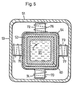
- a Kobille is designated on average. It consists of a mold tube 52 made of copper and a mold jacket 53. A cooling jacket 54 is arranged around the tube 52. Cooling water flows through the space between the mold 52 and the cooling jacket 54. A partially solidified strand 60 with a liquid core 61 is shown in the interior of the mold 52. This strand 60 is drawn from the mold by known means and cooled further.
- Magnetic poles 70, 71, 72, 73 are attached to each side of the cooling jacket 54, each of which is provided with a turn 74, 75, 76, 77. These magnetic poles are cooled by cooling water in the space between cooling jacket 54 and mold jacket 53. The turns 74, 75, 76, 77 are switched so that a traveling field is created. These magnetic poles form an electromagnetic field in the strand-inducing stirrer. According to the Glessparamater, one phase is fed with a 10-25% higher current than the other, subsequent phase. For a billet of 100 x 100 mm, the turns 74 and 76 are loaded with 400 A at a frequency of 50 Hz and a voltage of 50 V and the turns 75 and 77 with 320 A.
- the traveling field produces differently acting shear forces in the liquid steel, which, due to the arrangement of the magnetic poles described, cause the melt to rotate. If a slower penetration of the stirring effect or a lower stirring speed is desired, the frequency is reduced accordingly, especially with large wall thicknesses of the mold tube.
- the circuit can, however, also be selected such that the magnetic flux flows between the pole pairs 70, 72 or 71, 73 and the rotary movement is generated in this way with the aid of the magnetic field.
- the pole pairs 70, 72 are excited, for example, with 400 A and the pole pairs 71, 73 with 320 A.
- the number of poles can be increased for larger billet and bloom formats.
- the differently acting thrust forces can be generated by different geometric configurations of the phase coils, e.g. B. by different number of turns.
- stirring was described with an arcuate thrust in the mold. However, this stirring can also be used in the secondary cooling zone. Instead of the arc-shaped direction of thrust, the straight-line direction of thrust running in the longitudinal direction of the strand can also be used in the mold.
- the method according to the invention can be used for all types of continuous casting plants with continuous molds, also for plants for casting beam pre-profiles and non-ferrous metals. In the case of strands with long, liquid cores, several stirrers can work together.
Landscapes
- Engineering & Computer Science (AREA)
- Mechanical Engineering (AREA)
- Continuous Casting (AREA)
Priority Applications (1)
| Application Number | Priority Date | Filing Date | Title |
|---|---|---|---|
| AT79102611T ATE3250T1 (de) | 1978-07-28 | 1979-07-24 | Verfahren zum stranggiessen von metall in eine kokille und einwirkung eines elektromagnetischen feldes. |
Applications Claiming Priority (6)
| Application Number | Priority Date | Filing Date | Title |
|---|---|---|---|
| CH813478A CH632172A5 (en) | 1978-07-28 | 1978-07-28 | Method for the continuous casting of steel |
| CH8134/78 | 1978-07-28 | ||
| CH102979A CH635012A5 (en) | 1979-02-02 | 1979-02-02 | Method for the continuous casting of steel |
| CH1029/79 | 1979-02-02 | ||
| CH1184/79 | 1979-02-07 | ||
| CH118479A CH635013A5 (en) | 1979-02-07 | 1979-02-07 | Method for the continuous casting of steel |
Publications (3)
| Publication Number | Publication Date |
|---|---|
| EP0008376A1 EP0008376A1 (de) | 1980-03-05 |
| EP0008376B1 EP0008376B1 (de) | 1983-05-11 |
| EP0008376B2 true EP0008376B2 (de) | 1989-04-05 |
Family
ID=27172616
Family Applications (1)
| Application Number | Title | Priority Date | Filing Date |
|---|---|---|---|
| EP19790102611 Expired EP0008376B2 (de) | 1978-07-28 | 1979-07-24 | Verfahren zum Stranggiessen von Metall in eine Kokille und Einwirkung eines elektromagnetischen Feldes |
Country Status (10)
| Country | Link |
|---|---|
| EP (1) | EP0008376B2 (pt) |
| AR (1) | AR217530A1 (pt) |
| AU (1) | AU528461B2 (pt) |
| BR (1) | BR7904814A (pt) |
| DD (1) | DD145069A5 (pt) |
| DE (2) | DE2965366D1 (pt) |
| DK (1) | DK147553C (pt) |
| ES (1) | ES483648A1 (pt) |
| FI (1) | FI63682C (pt) |
| SE (1) | SE440493B (pt) |
Families Citing this family (6)
| Publication number | Priority date | Publication date | Assignee | Title |
|---|---|---|---|---|
| SE410940C (sv) * | 1978-04-05 | 1986-01-27 | Asea Ab | Forfaringssett for omroring vid strenggjutning |
| SE430223B (sv) * | 1979-11-06 | 1983-10-31 | Asea Ab | Forfaringssett for omroring vid strenggjutning |
| CH646623A5 (de) * | 1980-03-20 | 1984-12-14 | Concast Ag | Verfahren und einrichtung zum stuetzen eines im stranggiess-verfahren hergestellten stahlstranges, dessen fluessiger kern elektromagnetisch geruehrt wird. |
| CH650429A5 (de) * | 1980-10-30 | 1985-07-31 | Concast Holding Ag | Verfahren zum stranggiessen von stahl, insbesondere von brammen. |
| FR2530510B1 (fr) * | 1982-07-23 | 1985-07-05 | Cegedur | Procede de coulee electromagnetique de metaux dans lequel on fait agir au moins un champ magnetique different du champ de confinement |
| AT378138B (de) * | 1983-11-04 | 1985-06-25 | Voest Alpine Ag | Ruehreinrichtung an einer stranggiessanlage |
Family Cites Families (4)
| Publication number | Priority date | Publication date | Assignee | Title |
|---|---|---|---|---|
| DE6930213U (de) * | 1969-07-28 | 1970-07-30 | Mannesmann Ag | Anordnung von wechselstromdurchflossenen spulen in einer brammen-stranggiessanlage |
| SE410153B (sv) * | 1976-05-21 | 1979-10-01 | Asea Ab | Anleggning vid strenggjutning |
| LU76942A1 (pt) * | 1977-03-14 | 1978-10-18 | ||
| SE410940C (sv) * | 1978-04-05 | 1986-01-27 | Asea Ab | Forfaringssett for omroring vid strenggjutning |
-
1979
- 1979-07-24 EP EP19790102611 patent/EP0008376B2/de not_active Expired
- 1979-07-24 FI FI792307A patent/FI63682C/fi not_active IP Right Cessation
- 1979-07-24 DE DE7979102611T patent/DE2965366D1/de not_active Expired
- 1979-07-25 AU AU49220/79A patent/AU528461B2/en not_active Ceased
- 1979-07-25 DD DD21460979A patent/DD145069A5/de unknown
- 1979-07-25 AR AR27744179A patent/AR217530A1/es active
- 1979-07-26 DE DE19792930281 patent/DE2930281B2/de not_active Ceased
- 1979-07-26 BR BR7904814A patent/BR7904814A/pt unknown
- 1979-07-27 DK DK317279A patent/DK147553C/da not_active IP Right Cessation
- 1979-07-27 SE SE7906413A patent/SE440493B/sv unknown
- 1979-07-27 ES ES483648A patent/ES483648A1/es not_active Expired
Also Published As
| Publication number | Publication date |
|---|---|
| DK147553B (da) | 1984-10-01 |
| EP0008376B1 (de) | 1983-05-11 |
| DE2930281B2 (de) | 1981-06-04 |
| DD145069A5 (de) | 1980-11-19 |
| DE2965366D1 (en) | 1983-06-16 |
| FI792307A (fi) | 1980-01-29 |
| FI63682B (fi) | 1983-04-29 |
| BR7904814A (pt) | 1980-04-22 |
| AU528461B2 (en) | 1983-04-28 |
| DE2930281A1 (de) | 1980-02-14 |
| EP0008376A1 (de) | 1980-03-05 |
| SE440493B (sv) | 1985-08-05 |
| AR217530A1 (es) | 1980-03-31 |
| SE7906413L (sv) | 1980-01-29 |
| AU4922079A (en) | 1980-01-31 |
| ES483648A1 (es) | 1980-04-16 |
| DK147553C (da) | 1985-03-04 |
| FI63682C (fi) | 1983-08-10 |
| DK317279A (da) | 1980-01-29 |
Similar Documents
| Publication | Publication Date | Title |
|---|---|---|
| DE2731238A1 (de) | Verfahren und vorrichtung zum kontinuierlichen vergiessen insbesondere von stahl unter einwirkung eines magnetischen wanderfeldes | |
| DE69231800T2 (de) | Verfahren zum Giessen von Ingots mit durch Verwendung eines magnetischen Feldes verringerter Makroseigerung, Vorrichtung und Ingot | |
| DE69710808T2 (de) | Verfahren und Vorrichtung zum Stranggiessen unter Verwendung von mehreren elektromagnetischen Rührern | |
| DE2720391A1 (de) | Anordnung beim stranggiessen | |
| DE69219317T2 (de) | Verfahren und vorrichtung zum giessen in eine form | |
| DE2401145A1 (de) | Verfahren und vorrichtung zum kontinuierlichen giessen | |
| EP0008376B2 (de) | Verfahren zum Stranggiessen von Metall in eine Kokille und Einwirkung eines elektromagnetischen Feldes | |
| AT397477B (de) | Verfahren und vorrichtung zum stranggiessen von metallen | |
| EP0850116B1 (de) | Elektromagnetische einrichtung für eine stranggiesskokille | |
| DE69224148T2 (de) | Verfahren zum elektromagnetischen Führen beim stranggiessen | |
| EP0028761B1 (de) | Verfahren zum Umrühren beim Stranggiessen | |
| DE69614274T2 (de) | Verfahren und vorrichtung zum giessen von metall | |
| DE2704918A1 (de) | Verfahren zum kontinuierlichen vergiessen von schmelzfluessigen metallen im magnetischen drehfeld | |
| DE2911842A1 (de) | Verfahren zum umruehren beim stranggiessen | |
| CH632431A5 (de) | Verfahren zum stranggiessen von stahl. | |
| DE602004005978T2 (de) | Stranggussverfahren für stahl | |
| DE69110166T3 (de) | Verfahren und Vorrichtung zum Stranggiessen von Stahlschmelzen. | |
| DE69702268T2 (de) | Stranggiessanlage | |
| DE69403950T3 (de) | Magnetisches Rühren mittels Wechselstrom für das kontinuierliche Gießen von Metallen | |
| CH645046A5 (de) | Verfahren zum kontinuierlichen giessen von stahl. | |
| DE2804487A1 (de) | Vorrichtung zur zugabe schmelzfluessigen metalls nach dem elektro- schlacke-umschmelzverfahren | |
| DE1803473A1 (de) | Verfahren und Einrichtung zum Metall-,insbesondere Stahl-Stranggiessen | |
| CH632172A5 (en) | Method for the continuous casting of steel | |
| DE2810876A1 (de) | Verfahren und vorrichtung zum umruehren von im schmelzzustand befindlichen metallen waehrend des kontinuierlichen giessens von brammen | |
| EP0013441A1 (de) | Einrichtung und Verfahren zum elektromagnetischen Rühren in einer Stahlstranggiessanlage |
Legal Events
| Date | Code | Title | Description |
|---|---|---|---|
| PUAI | Public reference made under article 153(3) epc to a published international application that has entered the european phase |
Free format text: ORIGINAL CODE: 0009012 |
|
| AK | Designated contracting states |
Designated state(s): AT BE CH DE FR GB IT LU NL SE |
|
| 17P | Request for examination filed | ||
| ITCL | It: translation for ep claims filed |
Representative=s name: BARZANO' E ZANARDO ROMA S.P.A. |
|
| ITF | It: translation for a ep patent filed | ||
| GRAA | (expected) grant |
Free format text: ORIGINAL CODE: 0009210 |
|
| AK | Designated contracting states |
Designated state(s): AT BE CH DE FR GB IT LU NL SE |
|
| REF | Corresponds to: |
Ref document number: 3250 Country of ref document: AT Date of ref document: 19830515 Kind code of ref document: T |
|
| REF | Corresponds to: |
Ref document number: 2965366 Country of ref document: DE Date of ref document: 19830616 |
|
| PGFP | Annual fee paid to national office [announced via postgrant information from national office to epo] |
Ref country code: LU Payment date: 19830622 Year of fee payment: 5 |
|
| ET | Fr: translation filed | ||
| PG25 | Lapsed in a contracting state [announced via postgrant information from national office to epo] |
Ref country code: LU Free format text: LAPSE BECAUSE OF NON-PAYMENT OF DUE FEES Effective date: 19830731 |
|
| PLBI | Opposition filed |
Free format text: ORIGINAL CODE: 0009260 |
|
| 26 | Opposition filed |
Opponent name: ASEA AKTIEBOLAG Effective date: 19840207 Opponent name: VOEST-ALPINE AKTIENGESELLSCHAFT Effective date: 19840207 |
|
| PGFP | Annual fee paid to national office [announced via postgrant information from national office to epo] |
Ref country code: SE Payment date: 19840630 Year of fee payment: 6 Ref country code: BE Payment date: 19840630 Year of fee payment: 6 |
|
| PGFP | Annual fee paid to national office [announced via postgrant information from national office to epo] |
Ref country code: FR Payment date: 19840731 Year of fee payment: 6 |
|
| PGFP | Annual fee paid to national office [announced via postgrant information from national office to epo] |
Ref country code: DE Payment date: 19840828 Year of fee payment: 6 |
|
| PGFP | Annual fee paid to national office [announced via postgrant information from national office to epo] |
Ref country code: CH Payment date: 19841017 Year of fee payment: 6 |
|
| PGFP | Annual fee paid to national office [announced via postgrant information from national office to epo] |
Ref country code: AT Payment date: 19860609 Year of fee payment: 8 |
|
| PGFP | Annual fee paid to national office [announced via postgrant information from national office to epo] |
Ref country code: NL Payment date: 19870731 Year of fee payment: 9 |
|
| ITF | It: translation for a ep patent filed | ||
| PUAH | Patent maintained in amended form |
Free format text: ORIGINAL CODE: 0009272 |
|
| STAA | Information on the status of an ep patent application or granted ep patent |
Free format text: STATUS: PATENT MAINTAINED AS AMENDED |
|
| 27A | Patent maintained in amended form |
Effective date: 19890405 |
|
| AK | Designated contracting states |
Kind code of ref document: B2 Designated state(s): AT BE CH DE FR GB IT LU NL SE |
|
| ET3 | Fr: translation filed ** decision concerning opposition | ||
| NLR2 | Nl: decision of opposition | ||
| NLR3 | Nl: receipt of modified translations in the netherlands language after an opposition procedure | ||
| PG25 | Lapsed in a contracting state [announced via postgrant information from national office to epo] |
Ref country code: GB Effective date: 19890724 Ref country code: AT Effective date: 19890724 |
|
| PG25 | Lapsed in a contracting state [announced via postgrant information from national office to epo] |
Ref country code: SE Effective date: 19890725 |
|
| PG25 | Lapsed in a contracting state [announced via postgrant information from national office to epo] |
Ref country code: CH Effective date: 19890731 Ref country code: BE Effective date: 19890731 |
|
| BERE | Be: lapsed |
Owner name: CONCAST HOLDING A.G. Effective date: 19890731 |
|
| PG25 | Lapsed in a contracting state [announced via postgrant information from national office to epo] |
Ref country code: NL Effective date: 19900201 |
|
| GBPC | Gb: european patent ceased through non-payment of renewal fee | ||
| NLV4 | Nl: lapsed or anulled due to non-payment of the annual fee | ||
| PG25 | Lapsed in a contracting state [announced via postgrant information from national office to epo] |
Ref country code: FR Free format text: LAPSE BECAUSE OF NON-PAYMENT OF DUE FEES Effective date: 19900330 |
|
| REG | Reference to a national code |
Ref country code: CH Ref legal event code: PL |
|
| PG25 | Lapsed in a contracting state [announced via postgrant information from national office to epo] |
Ref country code: DE Effective date: 19900403 |
|
| REG | Reference to a national code |
Ref country code: FR Ref legal event code: ST |
|
| EUG | Se: european patent has lapsed |
Ref document number: 79102611.5 Effective date: 19900418 |