EP0005137B1 - Stellantrieb für ein Verschlussorgan, insbesondere einen Lüftungsschieber oder eine Lüftungsklappe einer Lüftungsvorrichtung oder dgl. - Google Patents
Stellantrieb für ein Verschlussorgan, insbesondere einen Lüftungsschieber oder eine Lüftungsklappe einer Lüftungsvorrichtung oder dgl. Download PDFInfo
- Publication number
- EP0005137B1 EP0005137B1 EP78101783A EP78101783A EP0005137B1 EP 0005137 B1 EP0005137 B1 EP 0005137B1 EP 78101783 A EP78101783 A EP 78101783A EP 78101783 A EP78101783 A EP 78101783A EP 0005137 B1 EP0005137 B1 EP 0005137B1
- Authority
- EP
- European Patent Office
- Prior art keywords
- ventilation
- make
- break contact
- motor
- register
- Prior art date
- Legal status (The legal status is an assumption and is not a legal conclusion. Google has not performed a legal analysis and makes no representation as to the accuracy of the status listed.)
- Expired
Links
- 238000009423 ventilation Methods 0.000 title claims description 38
- 230000001360 synchronised effect Effects 0.000 claims description 27
- 230000007246 mechanism Effects 0.000 claims description 11
- 230000006378 damage Effects 0.000 description 4
- 230000001960 triggered effect Effects 0.000 description 4
- 230000002265 prevention Effects 0.000 description 3
- 230000004044 response Effects 0.000 description 2
- 230000008901 benefit Effects 0.000 description 1
- 230000008859 change Effects 0.000 description 1
- 230000000694 effects Effects 0.000 description 1
- 230000005284 excitation Effects 0.000 description 1
- 238000000034 method Methods 0.000 description 1
- 230000008569 process Effects 0.000 description 1
Images

Classifications
-
- E—FIXED CONSTRUCTIONS
- E05—LOCKS; KEYS; WINDOW OR DOOR FITTINGS; SAFES
- E05F—DEVICES FOR MOVING WINGS INTO OPEN OR CLOSED POSITION; CHECKS FOR WINGS; WING FITTINGS NOT OTHERWISE PROVIDED FOR, CONCERNED WITH THE FUNCTIONING OF THE WING
- E05F15/00—Power-operated mechanisms for wings
- E05F15/60—Power-operated mechanisms for wings using electrical actuators
- E05F15/603—Power-operated mechanisms for wings using electrical actuators using rotary electromotors
-
- E—FIXED CONSTRUCTIONS
- E05—LOCKS; KEYS; WINDOW OR DOOR FITTINGS; SAFES
- E05F—DEVICES FOR MOVING WINGS INTO OPEN OR CLOSED POSITION; CHECKS FOR WINGS; WING FITTINGS NOT OTHERWISE PROVIDED FOR, CONCERNED WITH THE FUNCTIONING OF THE WING
- E05F15/00—Power-operated mechanisms for wings
- E05F15/40—Safety devices, e.g. detection of obstructions or end positions
-
- E—FIXED CONSTRUCTIONS
- E05—LOCKS; KEYS; WINDOW OR DOOR FITTINGS; SAFES
- E05F—DEVICES FOR MOVING WINGS INTO OPEN OR CLOSED POSITION; CHECKS FOR WINGS; WING FITTINGS NOT OTHERWISE PROVIDED FOR, CONCERNED WITH THE FUNCTIONING OF THE WING
- E05F15/00—Power-operated mechanisms for wings
- E05F15/60—Power-operated mechanisms for wings using electrical actuators
- E05F15/603—Power-operated mechanisms for wings using electrical actuators using rotary electromotors
- E05F15/632—Power-operated mechanisms for wings using electrical actuators using rotary electromotors for horizontally-sliding wings
-
- H—ELECTRICITY
- H02—GENERATION; CONVERSION OR DISTRIBUTION OF ELECTRIC POWER
- H02K—DYNAMO-ELECTRIC MACHINES
- H02K19/00—Synchronous motors or generators
- H02K19/02—Synchronous motors
- H02K19/04—Synchronous motors for single-phase current
-
- H—ELECTRICITY
- H02—GENERATION; CONVERSION OR DISTRIBUTION OF ELECTRIC POWER
- H02K—DYNAMO-ELECTRIC MACHINES
- H02K7/00—Arrangements for handling mechanical energy structurally associated with dynamo-electric machines, e.g. structural association with mechanical driving motors or auxiliary dynamo-electric machines
- H02K7/06—Means for converting reciprocating motion into rotary motion or vice versa
-
- E—FIXED CONSTRUCTIONS
- E05—LOCKS; KEYS; WINDOW OR DOOR FITTINGS; SAFES
- E05F—DEVICES FOR MOVING WINGS INTO OPEN OR CLOSED POSITION; CHECKS FOR WINGS; WING FITTINGS NOT OTHERWISE PROVIDED FOR, CONCERNED WITH THE FUNCTIONING OF THE WING
- E05F15/00—Power-operated mechanisms for wings
- E05F15/70—Power-operated mechanisms for wings with automatic actuation
- E05F15/73—Power-operated mechanisms for wings with automatic actuation responsive to movement or presence of persons or objects
-
- E—FIXED CONSTRUCTIONS
- E05—LOCKS; KEYS; WINDOW OR DOOR FITTINGS; SAFES
- E05Y—INDEXING SCHEME ASSOCIATED WITH SUBCLASSES E05D AND E05F, RELATING TO CONSTRUCTION ELEMENTS, ELECTRIC CONTROL, POWER SUPPLY, POWER SIGNAL OR TRANSMISSION, USER INTERFACES, MOUNTING OR COUPLING, DETAILS, ACCESSORIES, AUXILIARY OPERATIONS NOT OTHERWISE PROVIDED FOR, APPLICATION THEREOF
- E05Y2400/00—Electronic control; Electrical power; Power supply; Power or signal transmission; User interfaces
- E05Y2400/10—Electronic control
- E05Y2400/30—Electronic control of motors
- E05Y2400/302—Electronic control of motors during electric motor braking
-
- E—FIXED CONSTRUCTIONS
- E05—LOCKS; KEYS; WINDOW OR DOOR FITTINGS; SAFES
- E05Y—INDEXING SCHEME ASSOCIATED WITH SUBCLASSES E05D AND E05F, RELATING TO CONSTRUCTION ELEMENTS, ELECTRIC CONTROL, POWER SUPPLY, POWER SIGNAL OR TRANSMISSION, USER INTERFACES, MOUNTING OR COUPLING, DETAILS, ACCESSORIES, AUXILIARY OPERATIONS NOT OTHERWISE PROVIDED FOR, APPLICATION THEREOF
- E05Y2400/00—Electronic control; Electrical power; Power supply; Power or signal transmission; User interfaces
- E05Y2400/10—Electronic control
- E05Y2400/44—Sensors not directly associated with the wing movement
- E05Y2400/445—Switches
-
- E—FIXED CONSTRUCTIONS
- E05—LOCKS; KEYS; WINDOW OR DOOR FITTINGS; SAFES
- E05Y—INDEXING SCHEME ASSOCIATED WITH SUBCLASSES E05D AND E05F, RELATING TO CONSTRUCTION ELEMENTS, ELECTRIC CONTROL, POWER SUPPLY, POWER SIGNAL OR TRANSMISSION, USER INTERFACES, MOUNTING OR COUPLING, DETAILS, ACCESSORIES, AUXILIARY OPERATIONS NOT OTHERWISE PROVIDED FOR, APPLICATION THEREOF
- E05Y2900/00—Application of doors, windows, wings or fittings thereof
- E05Y2900/10—Application of doors, windows, wings or fittings thereof for buildings or parts thereof
- E05Y2900/13—Type of wing
- E05Y2900/132—Doors
-
- E—FIXED CONSTRUCTIONS
- E05—LOCKS; KEYS; WINDOW OR DOOR FITTINGS; SAFES
- E05Y—INDEXING SCHEME ASSOCIATED WITH SUBCLASSES E05D AND E05F, RELATING TO CONSTRUCTION ELEMENTS, ELECTRIC CONTROL, POWER SUPPLY, POWER SIGNAL OR TRANSMISSION, USER INTERFACES, MOUNTING OR COUPLING, DETAILS, ACCESSORIES, AUXILIARY OPERATIONS NOT OTHERWISE PROVIDED FOR, APPLICATION THEREOF
- E05Y2900/00—Application of doors, windows, wings or fittings thereof
- E05Y2900/10—Application of doors, windows, wings or fittings thereof for buildings or parts thereof
- E05Y2900/13—Type of wing
- E05Y2900/148—Windows
Definitions
- the invention relates to an actuator for a closure member, in particular a ventilation slide or a ventilation flap of a ventilation device or the like, consisting of a self-starting single-phase AC synchronous motor, through which the ventilation slide or the ventilation flap between two predetermined end positions, namely a closed position and one Open position, movable back and forth and can be stopped in any preselectable of these end positions, the respective end position being preselectable via a change-over contact and controllable via two switches arranged downstream of this in different line branches, which can be opened and closed by a cam disk driven by the single-phase AC synchronous motor .
- actuators for actuating locking devices for breakthroughs in building walls, in particular doors, window and ventilation openings must be designed so that at least the closing process of the locking devices is immediately interrupted if there is a risk of getting caught.
- US Pat. No. 3,870,274 already includes an actuator for a valve of a radiator which is equipped with a self-starting single-phase AC synchronous motor.
- the valve flap can be moved back and forth between two predetermined end positions, namely a closed position and an open position of the valve flap, and can be stopped in an arbitrarily preselectable end position by means of the single-phase AC synchronous motor.
- the respective end position for the valve flap can also be preselected via a changeover contact and can be controlled via two switches arranged downstream of this changeover contact in different line branches, which in turn can be opened and closed by a cam disk which can be driven by the single-phase AC synchronous motor.
- each possible end position of the valve flap forming the actuator is assigned a mechanical stop against which the actuator starts when the single-phase AC synchronous motor should start in the direction of rotation which is opposite to the desired direction of adjustment. Only the resistance caused by the actuation of the actuator against the mechanical stop then - due to the operating characteristics of the single-phase alternating current synchronous motor - leads to a reversal of the direction of rotation, by which the actuator is then moved in the desired direction.
- the object of the invention is to provide an actuator of the generic type for closing members of wall openings in buildings or the like, in particular for a ventilation slide or a ventilation flap of a ventilation device, by means of which the closing member, for example, the ventilation slide or the ventilation flap, without mechanical stop Aid from the respective end position is driven directly in the correct direction of movement, regardless of the direction in which the single-phase AC synchronous motor starts. Nevertheless, it should be ensured that obstacles which accidentally or deliberately get into the path of movement during the adjustment movement of the closure member after leaving one end position and before reaching the other end position, spontaneously reverse the movement of the single-phase AC synchronous motor without this Locking member remains in the end position it has just left.
- the closure member should maintain the respective direction of rotation of the single-phase change Selstrom synchronous motor run through this end position again in the specified direction of movement to get to the preselected other end position.
- This complex problem is solved according to the invention in that the single-phase alternating current synchronous motor is in an actuating connection via a push-crank mechanism with the closure element, for example the ventilation slide or the ventilation flap, which determines the closed position and the open position of the closure element with a dead center position. and that the switch that can be opened and closed via the cam disk are assigned to the two dead center positions of the thrust crank mechanism, while only between the two dead center positions are mobile obstacles in the travel path of the closure member forming direct mechanical reversing stops for the single-phase AC synchronous motor.
- the closure member Due to the two dead center positions of the thrust crank drive, the closure member can be fixed in a simple manner both in its closed position and in its open position and thus blocked against adjustment by external force effects without additional mechanical stops. However, as soon as the closure member has moved away from its closed position or its open position, external forces acting on it automatically cause evasive movements which prevent both overloading and injuries.
- a further changeover contact which can be operated by remote control is provided and is arranged in one of the two line branches which can be controlled by the manually operated changeover contact, in such a way that either one or the other switch can be connected to one line branch via the remotely controllable changeover contact.
- the manually operated changeover contact practically takes over the function of a main switch, while the changeover contact which can be actuated by remote control acts as an auxiliary switch, which takes over the function control for the actuator in a very specific active position of the main switch.
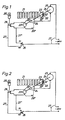
- FIG. 1 to 4 show in a schematically simplified representation the arrangement and mode of operation of an actuator according to the invention for the actuation of a ventilation slide during various phases of work.
- 1 to 4 of the drawing is an actuator in connection with one which releases or blocks the air passage openings of a ventilation device.
- a thrust crank mechanism 22 which consists of a crank pin 22 ′ seated on a disk 23 and a sliding link 22 ′′ formed on the slide 21.
- the disk 23 is keyed in a rotationally fixed manner on a shaft 24, which drives the drive, which is designed as a geared motor.
- Single-phase AC synchronous motor 25 forms.
- a cam disk 23 ' is also non-rotatably seated on the drive shaft 24, in such a way that it executes an angular rotation corresponding to the disk 23.
- the slide 21 In the closed position of the ventilation device, the slide 21 assumes the position shown in FIGS. 1 and 2, in which the crank pin 22 'seated on the disk 23 has the right dead center position in relation to the adjustment direction of the slide 21.
- the slide 21 When the ventilation device is open, the slide 21 is in the position shown in FIG. 3, i.e. the crank pin 22 'seated on the disk 23 assumes its left dead center position.
- the single-phase alternating current synchronous motor 25 can be connected to the network 27 via a manually operated switch designed as an alternating contact 26.
- the changeover contact 26 cooperates with two different line branches 27 ′ and 27 ′′ Embodiment placed a second changeover contact 28, which is remotely controllable, for example, via a relay 28 '.
- This change-over contact 28 cooperates with a further line branching, a micro switch 29 'being arranged in one and a micro switch 29 "in the other.
- the two micro switches 29' and 29" are controlled by the cam disk 23 '.
- the second line branch 27 ′′ assigned to the changeover contact 26 is connected directly to the line branch containing the microswitch 29 ′′.
- Opening the ventilation device by adjusting the slide 21 can only be triggered if the changeover contact 26 has previously been moved from its position according to FIG. 1 to the position according to FIG. 2, that is to say separated from the line branch 27 ′′ and connected to the line branch 27 ′.
- the changeover contact 28 is reset and thus via the microswitch 29 "the single-phase AC synchronous motor 25 is still connected to the network 27. Also in the left dead center position of the thrust crank mechanism 22 according to FIG. 3, it does not matter which direction of rotation the single-phase AC synchronous motor 25 starts to move the slide 21 back into its closed position.
- a braking resistor acts on the slide 21 during its movement brought about by the thrust crank mechanism 22, which is opposite to the respective direction of movement of the slide, then this acts back on the single-phase AC synchronous motor 25 via the thrust crank mechanism 22 and releases a slip of the field excitation curve in it towards the field magnet.
- This spontaneously results in a reversal of the direction of rotation of the single-phase alternating-current synchronous motor 25, by means of which the slide 21 automatically evades the existing braking resistor by moving in the opposite direction to the original direction of movement.
- the thrust crank mechanism 22 runs through its dead center position and thus moves the slide 21 again in the originally intended direction of adjustment.
- the slide 21 is brought into the intended end position and stopped there by opening the microswitch assigned to it.
- the remotely controllable changeover contact 28 is provided in the line branch 27 'in order to connect the microswitch 29' or the microswitch 29 "to this line branch 27 ', then the response of the relay 28' can be triggered by various events work together with a gas sensor that is sensitive to harmful or even unpleasant gas concentrations in rooms, but it is also possible to have the relay 28 'work with a sound sensor which responds when a certain external noise level is exceeded and via the relay 28' Changeover contact 28 is adjusted so that the ventilation device closes automatically if it is in its open position.
- the actuator described and claimed above can be used practically anywhere there. where it matters, power-operated locking devices for breakthroughs in building walls. such as door, window and ventilation openings, with the least possible technical effort and great robustness in accordance with the accident prevention guidelines so that there is a risk of trapping people. Body parts and objects are avoided.
Landscapes
- Engineering & Computer Science (AREA)
- Power Engineering (AREA)
- Power-Operated Mechanisms For Wings (AREA)
Applications Claiming Priority (2)
| Application Number | Priority Date | Filing Date | Title |
|---|---|---|---|
| DE2818461 | 1978-04-27 | ||
| DE19782818461 DE2818461A1 (de) | 1978-04-27 | 1978-04-27 | Anwendung eines selbstanlaufenden einphasen-wechselstrom-synchronmotors |
Publications (2)
| Publication Number | Publication Date |
|---|---|
| EP0005137A1 EP0005137A1 (de) | 1979-11-14 |
| EP0005137B1 true EP0005137B1 (de) | 1981-07-01 |
Family
ID=6038129
Family Applications (1)
| Application Number | Title | Priority Date | Filing Date |
|---|---|---|---|
| EP78101783A Expired EP0005137B1 (de) | 1978-04-27 | 1978-12-20 | Stellantrieb für ein Verschlussorgan, insbesondere einen Lüftungsschieber oder eine Lüftungsklappe einer Lüftungsvorrichtung oder dgl. |
Country Status (3)
| Country | Link |
|---|---|
| US (1) | US4319169A (enExample) |
| EP (1) | EP0005137B1 (enExample) |
| DE (1) | DE2818461A1 (enExample) |
Families Citing this family (14)
| Publication number | Priority date | Publication date | Assignee | Title |
|---|---|---|---|---|
| DE3340557A1 (de) * | 1983-11-09 | 1985-05-15 | Landert-Motoren-AG, Bülach, Zürich | Vorrichtung zum automatischen oeffnen und schliessen von schiebetueren |
| DE8713013U1 (de) * | 1987-09-26 | 1987-12-23 | Priebe, Hans-Werner, 3554 Lohra | Elektrische Steuer-Schalteinrichtung für an einer senkrechten Wand montierte Schrank- und/oder Tischmöbel, deren Positionen an der Wand elektromechanisch veränderbar sind |
| GB2213524A (en) * | 1987-12-15 | 1989-08-16 | Edos Limited | Sliding door operating mechanism |
| GB8902566D0 (en) * | 1989-02-06 | 1989-03-22 | Rotalac Plastics | Bi-parting shutter system |
| US4994724A (en) * | 1990-03-29 | 1991-02-19 | Hsu Chun Pu | Servo-controlled automatic door having automatic detecting and adjusting mechanism |
| FR2757205B1 (fr) * | 1996-12-13 | 1999-02-05 | Adronit Verwaltungs Gmbh Co | Porte coulissante pour entrees carrossables |
| AU2002358990A1 (en) * | 2002-11-25 | 2004-06-18 | Wittur S.P.A. | Motorisation for closing and opening automatic doors |
| CA2509669C (en) * | 2004-01-21 | 2008-12-30 | Philip Y. W. Tsui | System and methods for operating a barrier |
| US7170248B2 (en) * | 2004-01-21 | 2007-01-30 | Gallen Ka Leung Tsui | Systems and methods for operating a barrier |
| DE102004033304B4 (de) * | 2004-07-08 | 2008-04-17 | Dorma Gmbh + Co. Kg | Karusselltür |
| DE202011100831U1 (de) * | 2011-05-18 | 2011-11-16 | Sommer Antriebs- Und Funktechnik Gmbh | Tor mit einem Antriebssystem |
| CA2866051C (en) | 2013-10-04 | 2021-07-27 | The Chamberlain Group, Inc. | Movable barrier safety sensor override |
| CA3212302A1 (en) * | 2020-04-27 | 2021-11-04 | Carter Hoffmann, Llc | Door movement system for cabinet |
| US20220204265A1 (en) * | 2020-12-31 | 2022-06-30 | Invenda Group Ag | Devices for touchless operation of a product outlet door of a vending machine |
Family Cites Families (10)
| Publication number | Priority date | Publication date | Assignee | Title |
|---|---|---|---|---|
| US2225003A (en) * | 1938-09-06 | 1940-12-17 | Internat Elevator Company | Door operating mechanism |
| US3078407A (en) * | 1960-02-29 | 1963-02-19 | Franklin Electric Co Inc | Reversible motor drive mechanism |
| US3434027A (en) * | 1965-06-01 | 1969-03-18 | Amphenol Borg Electronics Corp | Self-reversing synchronous motor |
| DE1708417A1 (de) * | 1968-01-19 | 1970-06-11 | Schmidt Ohg Geb | Garagentorantrieb |
| FR2040576A5 (enExample) * | 1969-04-02 | 1971-01-22 | Crouzet & Cie | |
| DE2027816C3 (de) | 1970-06-05 | 1984-06-20 | Geze Gmbh, 7250 Leonberg | Sicherheitssteuerung für automatisch schließende Türen |
| US3611083A (en) * | 1970-11-12 | 1971-10-05 | Gen Motors Corp | Reversing control circuit for a single-phase alternating current induction motor |
| US3870274A (en) * | 1972-06-30 | 1975-03-11 | Chr Nielsens Eftf As | Motor driven valve |
| US4057934A (en) * | 1974-04-05 | 1977-11-15 | Hitachi, Ltd. | Protection system for automatically openable and closable door |
| US4010408A (en) * | 1975-03-13 | 1977-03-01 | Overhead Door Corporation | Switch mechanism for door operator |
-
1978
- 1978-04-27 DE DE19782818461 patent/DE2818461A1/de active Granted
- 1978-12-20 EP EP78101783A patent/EP0005137B1/de not_active Expired
-
1980
- 1980-10-27 US US06/201,203 patent/US4319169A/en not_active Expired - Lifetime
Also Published As
| Publication number | Publication date |
|---|---|
| US4319169A (en) | 1982-03-09 |
| DE2818461A1 (de) | 1979-11-08 |
| EP0005137A1 (de) | 1979-11-14 |
| DE2818461C2 (enExample) | 1987-07-30 |
Similar Documents
| Publication | Publication Date | Title |
|---|---|---|
| EP0005137B1 (de) | Stellantrieb für ein Verschlussorgan, insbesondere einen Lüftungsschieber oder eine Lüftungsklappe einer Lüftungsvorrichtung oder dgl. | |
| DE3538797C2 (enExample) | ||
| DE3519203A1 (de) | Stellvorrichtung fuer eine tuer eines kraftfahrzeugs | |
| DE202009005241U1 (de) | Durchgangssperre | |
| EP0715049A1 (de) | Drehtüranlage | |
| DE102005055788A1 (de) | Betätigungseinrichtung für ein bewegliches Bauteil | |
| DE69431543T2 (de) | ventilanordnung | |
| DE3028445C2 (de) | Sicherheitseinrichtung für motorisch bewegte Schließteile | |
| DE69312560T2 (de) | Automatische Arretiervorrichtung für den elektronischen Motorantrieb von Türen, Fensterläden, Rolläden und dergleichen | |
| DE3247018A1 (de) | Stelleinrichtung, insbesondere fuer tuerverriegelungsanlagen von kraftfahrzeugen | |
| DE4140197C2 (de) | Verfahren zum Verstellen eines fremdkraftbetätigbaren Bauteils | |
| DE2805009C2 (de) | Einrichtung zur elektrischen Zentralverriegelung von Türverschlüssen | |
| DE2104098A1 (de) | Ausgleichsventil | |
| DE3915736A1 (de) | Einrichtung zum betaetigen von schwenkbaren und/oder verschiebbaren karosserieteilen an kraftfahrzeugen | |
| DE3604083A1 (de) | Feststellvorrichtung fuer tuerfluegel mit einem tuerschliesser | |
| DE3130699A1 (de) | "omnibus mit einer kraftbetaetigten tuer" | |
| EP0074486B1 (de) | Schieberlüftung mit einem motorbetriebenen Gebläse | |
| DE1908607A1 (de) | Stellantrieb | |
| WO2020229676A1 (de) | Steuerung für tür- oder fensterantrieb | |
| DE3705043A1 (de) | Einklemmschutz fuer eine tuere | |
| DE69200753T2 (de) | Elektromechanische Antriebsvorrichtung für Kipptor, insbesondere für Garagenkipptor. | |
| DE2507967A1 (de) | Drehfalttor | |
| DE2037247A1 (de) | Schiebetür mit einer im Bedarfsfall ein sofortiges Wiederöffnen bewirkenden Einrichtung | |
| DE3105867A1 (de) | Schaltungsanordnung fuer druckmittelbetaetigte, insbesondere pneumatisch betaetigte, tueren in fahrzeugen, wie omnibussen, strassenbahnen o.dgl. | |
| EP0450326B1 (de) | Schaltvorrichtung für Antriebselemente von Schliessteilen in Kraftfahrzeugen |
Legal Events
| Date | Code | Title | Description |
|---|---|---|---|
| PUAI | Public reference made under article 153(3) epc to a published international application that has entered the european phase |
Free format text: ORIGINAL CODE: 0009012 |
|
| AK | Designated contracting states |
Designated state(s): BE CH FR GB NL SE |
|
| 17P | Request for examination filed | ||
| GRAA | (expected) grant |
Free format text: ORIGINAL CODE: 0009210 |
|
| AK | Designated contracting states |
Designated state(s): BE CH FR GB NL SE |
|
| PG25 | Lapsed in a contracting state [announced via postgrant information from national office to epo] |
Ref country code: SE Effective date: 19810701 |
|
| GBPC | Gb: european patent ceased through non-payment of renewal fee | ||
| PG25 | Lapsed in a contracting state [announced via postgrant information from national office to epo] |
Ref country code: GB Effective date: 19881118 |
|
| PGFP | Annual fee paid to national office [announced via postgrant information from national office to epo] |
Ref country code: CH Payment date: 19931126 Year of fee payment: 16 |
|
| PGFP | Annual fee paid to national office [announced via postgrant information from national office to epo] |
Ref country code: FR Payment date: 19931221 Year of fee payment: 16 |
|
| PGFP | Annual fee paid to national office [announced via postgrant information from national office to epo] |
Ref country code: NL Payment date: 19931231 Year of fee payment: 16 |
|
| PGFP | Annual fee paid to national office [announced via postgrant information from national office to epo] |
Ref country code: BE Payment date: 19940131 Year of fee payment: 16 |
|
| PG25 | Lapsed in a contracting state [announced via postgrant information from national office to epo] |
Ref country code: BE Effective date: 19941231 Ref country code: CH Effective date: 19941231 |
|
| BERE | Be: lapsed |
Owner name: SIEGENIA-FRANK K.G. Effective date: 19941231 |
|
| PG25 | Lapsed in a contracting state [announced via postgrant information from national office to epo] |
Ref country code: NL Effective date: 19950701 |
|
| PG25 | Lapsed in a contracting state [announced via postgrant information from national office to epo] |
Ref country code: FR Effective date: 19950831 |
|
| REG | Reference to a national code |
Ref country code: CH Ref legal event code: PL |
|
| NLV4 | Nl: lapsed or anulled due to non-payment of the annual fee |
Effective date: 19950701 |
|
| REG | Reference to a national code |
Ref country code: FR Ref legal event code: ST |
|
| PLBE | No opposition filed within time limit |
Free format text: ORIGINAL CODE: 0009261 |
|
| STAA | Information on the status of an ep patent application or granted ep patent |
Free format text: STATUS: NO OPPOSITION FILED WITHIN TIME LIMIT |