EP0003078A1 - Perfectionnements au plaquage par explosion - Google Patents
Perfectionnements au plaquage par explosion Download PDFInfo
- Publication number
- EP0003078A1 EP0003078A1 EP78300854A EP78300854A EP0003078A1 EP 0003078 A1 EP0003078 A1 EP 0003078A1 EP 78300854 A EP78300854 A EP 78300854A EP 78300854 A EP78300854 A EP 78300854A EP 0003078 A1 EP0003078 A1 EP 0003078A1
- Authority
- EP
- European Patent Office
- Prior art keywords
- plate
- flyer
- layer
- cladding
- explosive
- Prior art date
- Legal status (The legal status is an assumption and is not a legal conclusion. Google has not performed a legal analysis and makes no representation as to the accuracy of the status listed.)
- Withdrawn
Links
Images

Classifications
-
- B—PERFORMING OPERATIONS; TRANSPORTING
- B23—MACHINE TOOLS; METAL-WORKING NOT OTHERWISE PROVIDED FOR
- B23K—SOLDERING OR UNSOLDERING; WELDING; CLADDING OR PLATING BY SOLDERING OR WELDING; CUTTING BY APPLYING HEAT LOCALLY, e.g. FLAME CUTTING; WORKING BY LASER BEAM
- B23K20/00—Non-electric welding by applying impact or other pressure, with or without the application of heat, e.g. cladding or plating
- B23K20/06—Non-electric welding by applying impact or other pressure, with or without the application of heat, e.g. cladding or plating by means of high energy impulses, e.g. magnetic energy
- B23K20/08—Explosive welding
Definitions
- This invention relates to explosive cladding of structural metal members by a corrosion resistant metal layer and is particularly, although not exclusively, applicable to strip cladding across regions of fusion welded joints between two or more clad plates.
- the plate employed is usually steel, clad with a relatively thin layer of corrosion resistant metal such as, for example, titanium, and since it is not normally possible to fusion weld this layer to the base metal it is usually formed by explosive welding.
- the technique of forming this material is well known in the art.
- This method involves the use of a silver,titanium or copper insert which is laid within the gap and then bridged by an overlaid strip of titanium which is fusion welded to the titanium cladding along each side of the joint regicn.
- the insert acts as a filler material to prevent fatigue failure of the titanium strip and attendant welding.
- Similar techniques are employed for joining clad plate made in other such metallurgically incompatible combinations such as tantalum/steel and zirconium/steel.
- the object of this invention is to provide a less expensive,convenient method of surface cladding joints between clad metal plates which produces a high integrity weld.
- a method of applying a surface layer across a surface layer or joint between cladding layers on a clad metal plate or plates comprises forming a shallow chamfer along each opposing cladding layer edge and positioning over the said chamfers a corrosion resistant metal flyer-plate having a shallow generally V-shaped configuration, optionally applying a buffer layer of transmitting medium placed on the outside surface of the flyer-plate, further superimposing an explosive layer upon the flyer-plate or buffer layers and detonating the explosive layer so as to explosively weld the flyer-plate material at least to the cladding layers.
- a groove in the base metal layer of the clad plate centrally between the chamfered edges of the cladding layers, in order to facilitate positioning of the flyer-plate.
- the groove may conveniently be formed simultaneously with the chamfers of the cladding layers and effectively extends the chamfer surfaces.
- the invention is preferably applicable to the joint region of clad metal plates where two base metal plates have been fusion welded together.
- the flyer-plate may advantageously have integral extensions which become detached by the explosion, whereby high quality welds up to the flyer-plate edge are achieved.
- the extensions are conveniently defined by longitudinal grooves formed at the commencement of the extensions or by bending the extended flyer-plate along a line at the commencement of the extension in a direction outwardly from the base plate.
- each leg of the flyer-plate is provided with a pair of angled portions to provide for a partial weld to occur to the base or target as well as the cladding portions.
- the flyer-plate may be spaced apart from the base or target plate in order to modify the explosive weld between the flyer-plate and the base plate.
- a plastic explosive such as Metabel, (Registered Trade Mark) having a high detonation velocity is employed in the form of a flexible sheet.
- Metabel Registered Trade Mark
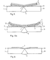
- the invention is applied to the fusion butt weld region joining two flat steel base plates 1 and lA.
- the cladding layers 2, 2A are machined back for a short distance from the weld region to prevent interference with the fusion welding process and shallow chamfers at an angle a are machined on the exposed ends of the cladding layers 2, 2A adjacent to the subsequently formed fusion weld zone 6.
- a rectangular flyer-plate 3 of cladding material compatible with the cladding layers 2, 2A is bent to a shallow generally 'V' configuration such that each side subtends an angle a and is closely positioned as shown.
- the sides may meet at an angle or on a radius along the apex.
- the angles a and ⁇ are determined on the basis of calculation of the required collision angle which provides the suitable set-up angle a-B required for explosive welding to take place.
- the flyer 3 will also be curved in side profile along the weld when the weld is curved or circumferential.
- the flyer-plate 3 is covered with a buffer layer 4 comprising a transmitting medium such as rubber and a layer of explosive medium 5 which is preferably a high detonation velocity explosive such as Metabel.
- the explosive medium 5 is detonated in the direction of the fusion weld seam, i.e. perpendicular to the section of the plate shown in Figure 1.
- the velocity of the flyer-plate 5 at impact is determined by the explosive loading and detonation velocity of layer 5; the collision angle and collision point velocity are determined by the velocity of the flyer-plate 3 and also by the angle ⁇ - ⁇ and may be calculated from a knowledge of the prior art.
- the extent of welding may be increased by forming an additional inclined portion 3B having an inclination of angle 8 to the target or base layers, 1, 1A so that inclined portion 3A form an angle a with the base 1, 1A and the portion 3B form a resultant angle ⁇ -S with the chamfers on the clad layers 2, 2A.
- the resultant weld after dressing is shown schematically in Figure 4 and it will be seen that welding of the flyer occurs right across the joint surface except for a narrow central region, due to the normal impact and the low stand-off.
- the edges of the cladding layers 2, and 2A and the portion of the base 1 and 1A adjacent to the weld 6 are machined at a chamfer angle a thereby forming a groove 7 above the weld 6, the angle a being the appropriately chosen welding angle.
- the flyer 3, with its sides including an angle 180°-2a is positioned with its apex in register in the groove 7.
- the flyer plate 3 advantageously has integral extensions 3C which can be coplanar with the flyer plate or bent upwards as shown.
- the flyer plate 3 has longitudinal grooves 8 at the commencement of the extensions.
- the buffer layer 4 and the explosive layer 5 covers all the area of flyer plate 3 and extensions 3C.
- the buffer layer 4 may also be locally thickened in the area immediately over the weld 6 for increased protection of the flyer plate in the region of the weld.
- the flyer or cladding plate 3 may be pre-formed with the buffer layer 4 and explosive charge layer 5 prior to welding and simple end jigs may be employed to maintain the required set-up geometry prior to detonation of the explosive layer.
- Welding may be performed on curved seams by using shaped (curved) flyers, provided that the correct relative angles are maintained.
- final closure of a full circumferential weld may not be achieved because of pressure doubling and overlap effects and therefore final closure of a small region only may require the more complex fusion welding technique to be employed.
- the method in accordance with the invention is applicable to seams lying in any direction or orientation, e.g. vertical, horizontal, overhead or downhand.
- Explosives whose detonation velocity fall within a wide range are suitable.
- plastic explosives such as Metabel which has a high detonation velocity, are preferred mainly on the grounds that they are readily moulded to shape and will stay in position without further packaging being required.
- an explosively welded seam can readily be inspected by ultrasonic techniques which are not applicable to fusion welded seams.
Applications Claiming Priority (2)
| Application Number | Priority Date | Filing Date | Title |
|---|---|---|---|
| GB185078 | 1978-01-17 | ||
| GB185078 | 1978-01-17 |
Publications (1)
| Publication Number | Publication Date |
|---|---|
| EP0003078A1 true EP0003078A1 (fr) | 1979-07-25 |
Family
ID=9729107
Family Applications (1)
| Application Number | Title | Priority Date | Filing Date |
|---|---|---|---|
| EP78300854A Withdrawn EP0003078A1 (fr) | 1978-01-17 | 1978-12-18 | Perfectionnements au plaquage par explosion |
Country Status (5)
| Country | Link |
|---|---|
| US (1) | US4272005A (fr) |
| EP (1) | EP0003078A1 (fr) |
| ES (1) | ES476937A1 (fr) |
| IT (1) | IT1110700B (fr) |
| ZA (1) | ZA7968B (fr) |
Cited By (2)
| Publication number | Priority date | Publication date | Assignee | Title |
|---|---|---|---|---|
| US5050789A (en) * | 1990-10-02 | 1991-09-24 | The United States Of America As Represented By The United States National Aeronautics And Space Administration | Apparatus and method for explosive bonding to edge of flyer plate |
| WO1993019885A1 (fr) * | 1992-04-02 | 1993-10-14 | Heinrich Hampel | Procede visant a ameliorer la resistance a la corrosion de soudures |
Families Citing this family (17)
| Publication number | Priority date | Publication date | Assignee | Title |
|---|---|---|---|---|
| US4552298A (en) * | 1983-04-29 | 1985-11-12 | The United States Of America As Represented By The Secretary Of The Navy | Apparatus for attaching an underwater explosive pad eye |
| US4708280A (en) * | 1985-10-23 | 1987-11-24 | The United States Of America As Represented By The Administrator, National Aeronautics & Space Administration | Tool and process for miniature explosive joining of tubes |
| US4688691A (en) * | 1986-01-22 | 1987-08-25 | Nooter Corporation | Process for attaching clad components and pressure vessel formed thereby |
| SE458908B (sv) * | 1986-11-07 | 1989-05-22 | Exploweld Ab | Foerfarande foer explosionssvetsning av tunna metallskikt |
| US5305946A (en) * | 1992-11-05 | 1994-04-26 | Nooter Corporation | Welding process for clad metals |
| CA2206035C (fr) * | 1997-05-23 | 2006-05-16 | Alexander Szecket | Joint hermetique profile a haute energie |
| KR20050020419A (ko) * | 2003-08-22 | 2005-03-04 | 주식회사 티에스엠텍 | 고급재질(티타늄, 지르코늄)의 화공유체용 탱크의용접선의 이음구조 및 이음방법 |
| AU2005200826B1 (en) * | 2005-02-24 | 2005-07-07 | W.E. Smith Engineering Pty Ltd | Method of joining clad metals and vessel produced thereby |
| US7588664B2 (en) * | 2005-07-27 | 2009-09-15 | Chicago Bridge & Iron Company | Oil distillation vacuum column with thickened plate in the vapor horn section |
| CN101239418B (zh) * | 2008-02-19 | 2011-07-06 | 江苏大学 | 一种飞片驱动式激光微焊接方法及装置 |
| FR2935625B1 (fr) * | 2008-09-05 | 2011-09-09 | Snecma | Procede de fabrication d'une piece thermamecanique de revolution circulaire comportant un substrat porteur a base de titane revetu d'acier ou superalliage, carter de compresseur de turbomachine resistant au feu de titane |
| RU2463139C1 (ru) * | 2011-04-13 | 2012-10-10 | Государственное образовательное учреждение высшего профессионального образования Волгоградский государственный технический университет (ВолгГТУ) | Способ получения композиционного материала титан-сталь |
| CN103433627B (zh) * | 2013-08-05 | 2015-04-22 | 江苏大学 | 一种简易的飞片粘贴及夹紧专用装置及其使用方法 |
| NL2011608C2 (nl) * | 2013-10-14 | 2015-06-16 | Synex Tube B V | Werkwijze voor het door middel van explosielassen aan elkaar bevestigen van ten minste twee metalen werkstukdelen. |
| US10279421B2 (en) | 2013-10-31 | 2019-05-07 | Halliburton Energy Services, Inc. | Wellbore servicing assemblies and methods of using the same |
| CN106181016A (zh) * | 2016-07-29 | 2016-12-07 | 西安交通大学 | 双金属层状复合板焊缝的电磁脉冲驱动焊接系统及方法 |
| US11576358B2 (en) * | 2018-03-30 | 2023-02-14 | Globeride, Inc. | Spigot joint fishing rod |
Citations (7)
| Publication number | Priority date | Publication date | Assignee | Title |
|---|---|---|---|---|
| DE129180C (fr) * | ||||
| GB953789A (en) * | 1962-03-01 | 1964-04-02 | Ici Ltd | Welding of laminar metallic elements |
| FR1414401A (fr) * | 1964-11-17 | 1965-10-15 | Wmf Wuerttemberg Metallwaren | Procédé et dispositif pour plaquer localement des pièces métalliques à l'aide d'une énergie produite par une explosion |
| BE681082A (fr) * | 1965-05-19 | 1966-10-31 | ||
| DE1232806B (de) * | 1962-10-24 | 1967-01-19 | Ici Ltd | Verfahren zum Verbinden zweier mit Abstand nebeneinander auf einem Grundmetall aufplattierter Schichten aus einem Auflagemetall |
| US3728780A (en) * | 1970-01-24 | 1973-04-24 | Inst Science And Technology | Explosive cladding on geometrically non-uniform metal material |
| FR2233129A1 (fr) * | 1973-06-12 | 1975-01-10 | Holland Explosive Metal |
Family Cites Families (5)
| Publication number | Priority date | Publication date | Assignee | Title |
|---|---|---|---|---|
| US3258841A (en) * | 1963-01-23 | 1966-07-05 | Du Pont | Method for explosively bonding metal layers |
| DE1248434B (de) * | 1963-11-18 | 1967-08-24 | Wmf Wuerttemberg Metallwaren | Anordnung zum vorzugsweise oertlichen Plattieren von metallischen Werkstuecken miteinander durch von Explosivstoffen erzeugte Schockwellen |
| SE324096B (fr) * | 1969-09-11 | 1970-05-19 | Asea Ab | |
| US3732612A (en) * | 1971-06-02 | 1973-05-15 | Martin Marietta Corp | Method for explosive bonding of metals |
| US3987952A (en) * | 1972-05-12 | 1976-10-26 | Exxon Research And Engineering Company | Apparatus for explosive welding of hollow cylinders such as pipe |
-
1978
- 1978-12-18 EP EP78300854A patent/EP0003078A1/fr not_active Withdrawn
-
1979
- 1979-01-08 ZA ZA00790068A patent/ZA7968B/xx unknown
- 1979-01-15 US US06/003,515 patent/US4272005A/en not_active Expired - Lifetime
- 1979-01-16 IT IT19333/79A patent/IT1110700B/it active
- 1979-01-17 ES ES476937A patent/ES476937A1/es not_active Expired
Patent Citations (7)
| Publication number | Priority date | Publication date | Assignee | Title |
|---|---|---|---|---|
| DE129180C (fr) * | ||||
| GB953789A (en) * | 1962-03-01 | 1964-04-02 | Ici Ltd | Welding of laminar metallic elements |
| DE1232806B (de) * | 1962-10-24 | 1967-01-19 | Ici Ltd | Verfahren zum Verbinden zweier mit Abstand nebeneinander auf einem Grundmetall aufplattierter Schichten aus einem Auflagemetall |
| FR1414401A (fr) * | 1964-11-17 | 1965-10-15 | Wmf Wuerttemberg Metallwaren | Procédé et dispositif pour plaquer localement des pièces métalliques à l'aide d'une énergie produite par une explosion |
| BE681082A (fr) * | 1965-05-19 | 1966-10-31 | ||
| US3728780A (en) * | 1970-01-24 | 1973-04-24 | Inst Science And Technology | Explosive cladding on geometrically non-uniform metal material |
| FR2233129A1 (fr) * | 1973-06-12 | 1975-01-10 | Holland Explosive Metal |
Cited By (2)
| Publication number | Priority date | Publication date | Assignee | Title |
|---|---|---|---|---|
| US5050789A (en) * | 1990-10-02 | 1991-09-24 | The United States Of America As Represented By The United States National Aeronautics And Space Administration | Apparatus and method for explosive bonding to edge of flyer plate |
| WO1993019885A1 (fr) * | 1992-04-02 | 1993-10-14 | Heinrich Hampel | Procede visant a ameliorer la resistance a la corrosion de soudures |
Also Published As
| Publication number | Publication date |
|---|---|
| ZA7968B (en) | 1979-12-27 |
| ES476937A1 (es) | 1979-07-16 |
| IT7919333A0 (it) | 1979-01-16 |
| US4272005A (en) | 1981-06-09 |
| IT1110700B (it) | 1985-12-23 |
Similar Documents
| Publication | Publication Date | Title |
|---|---|---|
| US4272005A (en) | Explosive cladding | |
| US3024879A (en) | Method of closing or joining integrated metal core panels and the structure produced | |
| CA1190067A (fr) | Methode d'assemblage de pieces en metal par soudage a deflagration | |
| GB986435A (en) | Joining clad metal parts | |
| CA1107466A (fr) | Revetement par voie d'explosifs | |
| US4901905A (en) | Charging system in the explosion welding of planar or curved workpieces | |
| EP3369513B1 (fr) | Joint par recouvrement soude à l'arc, et structure jointes avec parties de formation par pressage | |
| US3407280A (en) | Spot weld hem joints | |
| JPH09226886A (ja) | ライニングパネル | |
| JPS57124578A (en) | Joining method for steel sheet pile | |
| GB2027784A (en) | Lintels of Sheet Metal | |
| SU1196195A1 (ru) | "cпocoб дугoboй cbapkи bctыk oбoлoчek" | |
| SU1348707A1 (ru) | Сварной образец дл механических испытаний | |
| JPS5732880A (en) | One side welding method for tank base metal | |
| JPH0246313B2 (fr) | ||
| RU1818188C (ru) | Способ соединени внахлест листов из алюмини и стали | |
| SU1632694A1 (ru) | Способ контактной стыковой сварки оплавлением | |
| SU1687401A1 (ru) | Способ двухсторонней электронно-лучевой сварки | |
| SU946844A1 (ru) | Способ дуговой сварки плавлением | |
| JPS61134459A (ja) | 鉄筋の接合方法 | |
| SU1181830A1 (ru) | Способ электродуговой сварки чугуна | |
| JPS589779A (ja) | 突合せ溶接方法 | |
| JPH0459486B2 (fr) | ||
| JPS6257779A (ja) | ボツクス構造物内部補強プレ−トの溶接方法 | |
| JPS63123577A (ja) | 溶接施工法 |
Legal Events
| Date | Code | Title | Description |
|---|---|---|---|
| PUAI | Public reference made under article 153(3) epc to a published international application that has entered the european phase |
Free format text: ORIGINAL CODE: 0009012 |
|
| AK | Designated contracting states |
Designated state(s): BE CH DE FR GB LU NL SE |
|
| STAA | Information on the status of an ep patent application or granted ep patent |
Free format text: STATUS: THE APPLICATION HAS BEEN WITHDRAWN |
|
| 18W | Application withdrawn | ||
| RIN1 | Information on inventor provided before grant (corrected) |
Inventor name: ANDERSON, DAVID KEAY CRICHTON Inventor name: CLELAND, DAVID BLACKHALL Inventor name: JACKSON, PETER WOODALL |