EP0002146B1 - Mittel zum Versetzen von schweren Lasten über Land und/oder über einem unter Wasser stehenden oder nicht unter Wasser stehenden Strandteil - Google Patents
Mittel zum Versetzen von schweren Lasten über Land und/oder über einem unter Wasser stehenden oder nicht unter Wasser stehenden Strandteil Download PDFInfo
- Publication number
- EP0002146B1 EP0002146B1 EP78400164A EP78400164A EP0002146B1 EP 0002146 B1 EP0002146 B1 EP 0002146B1 EP 78400164 A EP78400164 A EP 78400164A EP 78400164 A EP78400164 A EP 78400164A EP 0002146 B1 EP0002146 B1 EP 0002146B1
- Authority
- EP
- European Patent Office
- Prior art keywords
- leg
- arms
- shoe
- fact
- sole
- Prior art date
- Legal status (The legal status is an assumption and is not a legal conclusion. Google has not performed a legal analysis and makes no representation as to the accuracy of the status listed.)
- Expired
Links
- XLYOFNOQVPJJNP-UHFFFAOYSA-N water Substances O XLYOFNOQVPJJNP-UHFFFAOYSA-N 0.000 claims description 23
- 230000008878 coupling Effects 0.000 claims description 11
- 238000010168 coupling process Methods 0.000 claims description 11
- 238000005859 coupling reaction Methods 0.000 claims description 11
- 238000006073 displacement reaction Methods 0.000 claims description 6
- 230000000903 blocking effect Effects 0.000 claims description 2
- 230000005484 gravity Effects 0.000 claims description 2
- 238000000926 separation method Methods 0.000 claims description 2
- 238000009877 rendering Methods 0.000 claims 1
- 230000000694 effects Effects 0.000 description 5
- 229910000831 Steel Inorganic materials 0.000 description 3
- 239000012530 fluid Substances 0.000 description 3
- 239000004033 plastic Substances 0.000 description 3
- 239000002689 soil Substances 0.000 description 3
- 239000010959 steel Substances 0.000 description 3
- XEEYBQQBJWHFJM-UHFFFAOYSA-N Iron Chemical compound [Fe] XEEYBQQBJWHFJM-UHFFFAOYSA-N 0.000 description 2
- 230000015556 catabolic process Effects 0.000 description 2
- 239000007788 liquid Substances 0.000 description 2
- 238000004519 manufacturing process Methods 0.000 description 2
- 239000000463 material Substances 0.000 description 2
- 239000013535 sea water Substances 0.000 description 2
- 229910001220 stainless steel Inorganic materials 0.000 description 2
- 239000010935 stainless steel Substances 0.000 description 2
- 239000000725 suspension Substances 0.000 description 2
- 229920002994 synthetic fiber Polymers 0.000 description 2
- 229910001018 Cast iron Inorganic materials 0.000 description 1
- 229910001208 Crucible steel Inorganic materials 0.000 description 1
- 240000002228 Cynara humilis Species 0.000 description 1
- 235000005921 Cynara humilis Nutrition 0.000 description 1
- 238000006424 Flood reaction Methods 0.000 description 1
- 240000008042 Zea mays Species 0.000 description 1
- 239000000872 buffer Substances 0.000 description 1
- KUNSUQLRTQLHQQ-UHFFFAOYSA-N copper tin Chemical group [Cu].[Sn] KUNSUQLRTQLHQQ-UHFFFAOYSA-N 0.000 description 1
- 238000005520 cutting process Methods 0.000 description 1
- 239000003599 detergent Substances 0.000 description 1
- 238000005868 electrolysis reaction Methods 0.000 description 1
- 239000013505 freshwater Substances 0.000 description 1
- 238000002347 injection Methods 0.000 description 1
- 239000007924 injection Substances 0.000 description 1
- 238000009434 installation Methods 0.000 description 1
- 229910052742 iron Inorganic materials 0.000 description 1
- 235000000396 iron Nutrition 0.000 description 1
- 239000000314 lubricant Substances 0.000 description 1
- 230000001050 lubricating effect Effects 0.000 description 1
- 239000002184 metal Substances 0.000 description 1
- 229910052751 metal Inorganic materials 0.000 description 1
- 238000000034 method Methods 0.000 description 1
- 239000000203 mixture Substances 0.000 description 1
- 239000003129 oil well Substances 0.000 description 1
- 238000005192 partition Methods 0.000 description 1
- -1 polytetrafluoroethylene Polymers 0.000 description 1
- 229920001343 polytetrafluoroethylene Polymers 0.000 description 1
- 239000004810 polytetrafluoroethylene Substances 0.000 description 1
- 238000002360 preparation method Methods 0.000 description 1
- 238000003825 pressing Methods 0.000 description 1
- 230000002787 reinforcement Effects 0.000 description 1
- 230000003014 reinforcing effect Effects 0.000 description 1
- 230000000284 resting effect Effects 0.000 description 1
- 239000004576 sand Substances 0.000 description 1
- 125000006850 spacer group Chemical group 0.000 description 1
- 238000009987 spinning Methods 0.000 description 1
- 238000003466 welding Methods 0.000 description 1
Images


Classifications
-
- B—PERFORMING OPERATIONS; TRANSPORTING
- B62—LAND VEHICLES FOR TRAVELLING OTHERWISE THAN ON RAILS
- B62D—MOTOR VEHICLES; TRAILERS
- B62D57/00—Vehicles characterised by having other propulsion or other ground- engaging means than wheels or endless track, alone or in addition to wheels or endless track
-
- B—PERFORMING OPERATIONS; TRANSPORTING
- B65—CONVEYING; PACKING; STORING; HANDLING THIN OR FILAMENTARY MATERIAL
- B65G—TRANSPORT OR STORAGE DEVICES, e.g. CONVEYORS FOR LOADING OR TIPPING, SHOP CONVEYOR SYSTEMS OR PNEUMATIC TUBE CONVEYORS
- B65G7/00—Devices for assisting manual moving or tilting heavy loads
-
- E—FIXED CONSTRUCTIONS
- E01—CONSTRUCTION OF ROADS, RAILWAYS, OR BRIDGES
- E01D—CONSTRUCTION OF BRIDGES, ELEVATED ROADWAYS OR VIADUCTS; ASSEMBLY OF BRIDGES
- E01D15/00—Movable or portable bridges; Floating bridges
- E01D15/24—Bridges or similar structures, based on land or on a fixed structure and designed to give access to ships or other floating structures
-
- E—FIXED CONSTRUCTIONS
- E02—HYDRAULIC ENGINEERING; FOUNDATIONS; SOIL SHIFTING
- E02B—HYDRAULIC ENGINEERING
- E02B17/00—Artificial islands mounted on piles or like supports, e.g. platforms on raisable legs or offshore constructions; Construction methods therefor
- E02B17/02—Artificial islands mounted on piles or like supports, e.g. platforms on raisable legs or offshore constructions; Construction methods therefor placed by lowering the supporting construction to the bottom, e.g. with subsequent fixing thereto
- E02B17/021—Artificial islands mounted on piles or like supports, e.g. platforms on raisable legs or offshore constructions; Construction methods therefor placed by lowering the supporting construction to the bottom, e.g. with subsequent fixing thereto with relative movement between supporting construction and platform
- E02B17/022—Artificial islands mounted on piles or like supports, e.g. platforms on raisable legs or offshore constructions; Construction methods therefor placed by lowering the supporting construction to the bottom, e.g. with subsequent fixing thereto with relative movement between supporting construction and platform adapted to travel on the bottom
-
- E—FIXED CONSTRUCTIONS
- E02—HYDRAULIC ENGINEERING; FOUNDATIONS; SOIL SHIFTING
- E02D—FOUNDATIONS; EXCAVATIONS; EMBANKMENTS; UNDERGROUND OR UNDERWATER STRUCTURES
- E02D29/00—Independent underground or underwater structures; Retaining walls
- E02D29/06—Constructions, or methods of constructing, in water
Definitions
- the present invention relates to means for moving, on land and / or on a submerged beach or not, heavy loads, which can be stranded amphibious pontoons and in particular factory pontoons.
- each pontoon constitutes a manufacturing unit in which the machines are mounted in a fixed position and are therefore usable directly, and that this manufacturing unit can easily be transported by river or sea to the point of use or near it.
- the factory pontoons were used while being kept afloat, which led to all contingencies linked to ships at quay, such as the precautions to be taken in the event of a storm, in the event of variable water levels due to floods. and the tides, etc.
- the sliding between the shoe and the sole can be improved by providing a lubricating material between their contact surfaces.
- the skid devices are permanently mounted on the vehicles.
- the machine is a factory pontoon for which the travel times are, in principle, much shorter than the downtime
- means of displacement are provided on land and / or on a beach submerged or not heavy loads comprising sets of crutches- practically vertical which can descend or climb in wells made in the load to be moved , each crutch carrying at its lower end, a pad which can slide on an associated sole, by means of jacks, the displacement of the load being obtained by lowering the crutches which raises the load, then by sliding the pads on their soles associated by controlling said jacks in one direction so as to move all of the load and the crutches relative to the soles applied to the ground, then by raising the crutches to place the load, and, finally, by moving the soles of the raised crutches relative to their pads by controlling said jacks in reverse, in which the crutches are removable and have, at their upper ends, hubs Locking ns for locking each crutch in a groove in each well, said locking means being automatically switched to the locking position when a crutch is threaded into a well and the locking means reach said groove,
- the locking means can be unlocked by an external control to remove each crutch from its well.
- each well is open at both ends to allow the exit or entry of a crutch by one end or the other, each shoe being removable so as to allow the passage of the crutch alone by the end top of the well.
- said locking means consist of two first lever arms pivoting symmetrically about a first axis secured to the top of the stand and two second lever arms pivoting symmetrically about a second axis, each second arm being respectively pivotally mounted on an arm so as to form an articulated quadrilateral with two pairs of arms, the second arms being appreciably shorter than the first arms, the first and second arms forming in the locked position angles open upwards less widely for the first arms whose ends are engaged in the groove of the well as for the second arms, said ends of the first arms carrying the load when the crutches are lowered and the second arms serving as flying buttresses preventing the first arms from closing when the stand is raised and therefore suspended from said locking means.
- the connecting means between the arm of a crutch and the associated pad consist of a key perpendicular to the direction of sliding of the pad, said key passing successively through holes provided in vertical tabs welded on the pads and diameter close to that of the key, and holes provided in the walls of the stand, characterized in that the diameter of the holes provided in the walls of the stand is larger than that of the key, so that, when the crutch supports the load, the bottom of the crutch rests directly on the shoe.
- said key has a head comprising a handle eccentricizing the center of gravity of the key and blocking any longitudinal movement of the latter, in the coupling position, but easily removable to allow separation of the pad from the stand.
- the stand consists of a jack whose top constitutes the top of the stand attached to said locking means and a vertical beam which is connected by coupling means which can be operated from the top of the top of the well a the end of the cylinder rod.
- patent FR-A-1 132 144 there is described a device for moving heavy loads, in which there is provided, at the lower part of the load, a compartment, open downwards, in which pressurized liquid is supplied during the movement of the load.
- a compartment open downwards, in which pressurized liquid is supplied during the movement of the load.
- water is injected under high pressure, so as to establish between said flat parts a film of water serving as lubricant.
- water is injected into a network of channels formed from the flat part of the sole and from a part dug in the flat part of the shoe, the channels forming branches distributed over the whole. of the skate surface.
- the actuating means of the jacks are hydraulic groups distributed par.zone and remotely controlled by electrical means, in order to distribute the actions on said jacks.
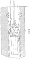
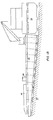
- the pontoon of FIG. 1 has a shell provided with at least two lateral rows of vertical wells 1 each containing a crutch 2.
- Each crutch 2 is provided at its lower end with a shoe 3 supporting a sole 4 with respect to which it can be subjected to sliding movements.
- Each stand 2 can go up or down in its associated well 1.
- the pontoon can float on water 5 and be moved either by its own means such as the propeller 6 associated with the rudder 7, or by external towing means, as long as there is enough water.
- the crutches 2 When there is no longer enough water or even no more water, the crutches 2 provided with their pads 3 and soles 4 still allow move the pontoon. In fact, the crutches can be lowered so as to lift the whole pontoon slightly as shown by the crutches 2a and 2b. By appropriate means, the shoes a and b are forced to slide on their respective flanges 4a and 4b, in the direction indicated by the arrow F1. Then, the crutches are raised relative to the pontoon, which has the effect of lowering the pontoon until it rests on the bottom, preferably flat, of its hull, the crutches being raised until their soles 4 are no longer in contact with the ground 8, as shown by the crutches 2c and 2d.
- the soles 4c and 4d are forced to slide under their respective pads 3c and 3d, always in the direction of the arrow F1. Then the crutches are lowered to raise the pontoon and so on. We then understand that it is possible to advance the pontoon of the relative runner-sole run with each operation which can be renewed fairly quickly.
- the soles 4 together have a total surface area sufficient not to sink into the same loose soil under the weight of the pontoon.
- the flat-bottomed shell has, on the two lateral edges of the bottom, at the junction with the vertical walls 9, instead of a projecting dihedral, a dihedral entering the horizontal part 10 from which the wells open 1.
- the width of the part 10 is slightly greater than that of the sole 4 of the skid of a crutch 2 and its height above the lowest part of the pontoon, here the underside of the bottom 11, slightly greater than the height of a sole 4 plus that of a skid 3, so that by raising the stand in the well the sole 4 can be completely released from the ground.
- the wells 1 open up above the water level 5 when the pontoon floats.
- the pontoon shell can be made of reinforced and vibrated concrete, transverse and longitudinal concrete partitions forming compartments which can serve as a wedge and a reservoir between the bottom 11 and the bridge 12.
- the bridge 12 can be surmounted by a metal frame superstructure 13 inside which a workshop can be housed, for example, provided with mobile hoists or cranes or lifting devices, such as 91, along the rows of wells 1.
- Each crutch 2 is provided at its upper end with locking means 14 to which a lifting cable 15 can be hung 15.
- the shoe 3 comprises hooking means 16 to which is fixed a cable launching 17.
- the cables 15 and 17 are actuated in a coordinated manner using the lifting devices 91.
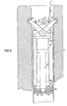
- Fig. 2 shows how it is possible to set up, in the open sea, a crutch 2 in a well 1.
- the cable 15 is lowered into well 1 and its end is recovered along the edge, then reassembled on deck 12.
- the cable 15 is raised in the well 1, which has the effect of placing the stand 2 in the position indicated in FIG. 1.
- the top of the stand is directed towards the lower opening of well 1, then goes back up there.
- the locking means 14 have reached their locking position, they are actuated and the head of the stand 2 is made integral, at a determined point, with the wall of the well 1.
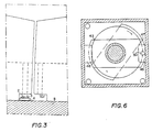
- the shoe 3 is mounted at the end of each stand body in a removable manner, the coupling means between the shoe 3 and the stand being shown in Figs. 7 and 8. as shown in FIG. 3, when two pontoons are placed side by side on the ground, once the crutches 2 removed from one of the pontoons, there is enough room under the rim 10 thereof to have access to the means for coupling the pads of the crutches on the other pontoon.
- the shoes uncoupled the bodies of crutches are recovered by means of the cable 15, after having unlocked the means 14, by raising the bodies of crutch inside the pontoon through the upper openings of the wells 1. It therefore appears that the crutches are only used when the pontoons are moving and do not remain unnecessarily immobilized between them.
- Fig. 4 shows the locking means 14 in the unlocked position, during the mounting of a stand 2 in a well 1, by example.
- the means 14 comprise two arms 18 and 19 articulated around a common axis 20, integral with the base 21 of a jack cylinder 22 mounted inside the body 23 of square section of a crutch.
- Each arm 18 or 19 has a free end 24 or 25, respectively, having a shape suitable for taking place in notches 26 or 27, respectively, provided in the opposite walls 28 and 29 of the well 1 with square section.
- Each arm 18 or 19 carries a horizontal axis 30 or 31, respectively, around which a short arm 32 or 33 is articulated, respectively.
- the arms 32 and 33 have their ends opposite respectively to 30 and 31 pivotally mounted on an axis 34 supported by a link 35 to which a piece of cable 15 is attached.
- the arms 18 and 19 form a largely open upward angle and have their respective ends 24 and 25 wedged in the notches 26 and 27.
- the axis 34 under the effect of the dead weight of the arms 32 and 33 descends a little below the horizontal line defined by the axes 30 and 31, the arms 32 and 33 form an angle largely open upwards, the sides of this angle being, for example, inclined approximately 6 ° with respect to the horizontal.
- the body 23 of the stand has an opening 36 through which one can pass, through the interior of the body 23, the end 37 of a hook extended by a rod 38 suspended from the end of a cable , not shown.
- the rod 38 is manipulated through the upper opening of the well, to hang the opening 36 at 37, then the cable which supports the rod 38 is stretched in order to support the crutch, no longer by the cable 15, but by the rod 38. Under the effect of their weight, the arms 18 and 19 open.
- the rod 38 is moved vertically to bring the ends 24 and 25 to engage in the notches 26 and 27, so that the arms 32 and 33 assume the position described in relation to FIG. 5.
- the locking is then completed and the rod 38 can be removed and the cable 15 detached.
- replace the rod 38, with its hook 37 in 36, to hold the crutch in place then hook the end of the cable 15 to 35 and stretch it to raise the axis 34 above the line of axes 30 and 31.
- the crutch is allowed to descend which brings out 24 and 25 from 26 and 27. We find the situation in FIG. 4, which allows either to leave the stand spinning in the water, or to take it out from above if the shoe has been previously dismantled.
- the notches 26 and 27 can in practice be constituted by a crown of cast iron or of cast steel 39 put in place during the pouring of the concrete constituting the walls of the well 1.
- the crown 39 may have a vertical section in inverted L or better in U, open towards the well, so that when the ends 24 and 25 are put in or removed, the chamfers 40 are not damaged.
- the ends 24 and 25 have a rectangular profile on three sides, corresponding to the three internal faces of the U 39, in order to match, with necessary clearance, the shape of the latter. It should be noted that, as the body 23 of the stand and the well have a square section, it is possible to hang the stand in the well in two perpendicular directions.
- a cylinder piston 42 In the cylinder 22 moves, under the action of either the weight supported by 22 or the hydraulic pressure of a fluid admitted into the cylinder by the piping 41, shown diagrammatically, a cylinder piston 42 whose end free crosses a coupling plate 43 which it crosses to be housed in the hollow 44 of a support plate 45, which is welded horizontally by its sides to the internal vertical walls of the body 23.
- a washer 46 Around the end of 42 , between the plate 43 and the plate 45, there is provided a washer 46 serving as a stop.
- the plate the coupling 43 has a relatively elongated general ectangular shape with, for example, slightly convex short sides f7, which, in the locked position of the plate 43, are accommodated under the buffers 48, formed of small plates welded to the corresponding faces of the body 23.
- the distance between 3 plane of the plates 48 and the plate 45 is it that the plate 43 can be housed between them n slightly crushing the washer 46.
- the plate 45 can be made to rise or rise relative to the cylinder 22, that is to say move the body 23 in the well 1 , the base 21 of the cylinder 22 both fixed relative to the well.
- Fig. 7 is a view in partial vertical section of the connection between the bottom of the body 23, one crutch 2 and a shoe 3, of which only the upper part is visible.
- Fig. 8 is a top view of this connection, with a horizontal section of the body 23, along the line VIII-VIII in FIG. 7.
- the lower end of the body 23 which, as we have seen in relation to Figs. 4 to 6, is a hollow metallic beam with section; arré, is obtained by cutting this beam according to a dihedron with horizontal edge, the half-planes of the dihedron being inclined symmetrically with respect to the horizontal by a maximum angle of 7 ° approximately and the edge being perpendicular iux sides of the body directed parallel to the direction of movement of the pontoon, in their midst. ; as shown in Fig. 8, the base thus created by the body 23 is reinforced by sheet plates 53 and 54 welded to the faces of 23 parallel to the displacement and cut, at the bottom, living the same dihedral.
- the lower edges of the body 23 and of the plates 53 to 54 rest directly on the upper face 55 of the shoe 3, when the shoe supports the stand 2.
- the plates 53 and 54, as well as the adjacent aces of 23 are pierced with two aligned holes 56 and 57.
- two thick vertical tabs 58 and 50 pierced with holes 60 and 61 respectively.
- a successively through the holes 60, 56, 57 and 61, can be threaded a pin 62, formed for example of a thick-walled tube, which secures the shoe and the body of the stand.
- the diameters of the orifices 56 and 57 are significantly greater than that of the pin 62 so that when the weight of the crutch is applied to the pad serving as support, the pin is not subjected to any force, the forces being applied to the surfaces of contact between 55 and the base of the body 23, as said above.
- the pin 62 lifts the shoe and the sole.
- the diameters of the holes 60 and 61 are equal, apart from the necessary clearance, to that of the pin 62.
- One end of the pin 62 is provided with a plate 63, which is welded to it and whose plane is perpendicular to the axis 62, the plate 63 being entirely on one side of the pin 62 relative to the axis of the latter so as to retain, by its weight, the angular position which is given to it once the pin is pressed.
- a vertical tab 64 On the face 55 of 3, beyond the plate 63, relative to 58, is provided a vertical tab 64, substantially in alignment with the pin 62, but with its upper edge 65 located below the defined cylinder by the pin 62.
- the plate 63 is allowed to fall by turning between 58 and 64, which ensures the locking of 62.
- plates of low height 66 to 69 which serve as stops to limit the relative translational movement between the body 23 and the shoe 3, despite the clearances between the pin 62 and the holes 58 and 59.
- Figs. 9 and 10 represent the assembly of the sole 4 on the shoe 3.
- the shoe 3 is constituted by an upper plate 70 and a lower plate 71 joined by spacers 72 to 75, which are vertical, 72 and 75 forming the lateral faces and 73 and 74 being at the base of the reinforcing plates 58 and 59.
- the sole 4 is longer than the shoe 3. It is constituted, like the shoe 3, by a welded assembly of steel plates and irons dishes, including in particular an upper plate 76 and a lower plate 77 resting on the ground.
- the upper face of the plate 76 is lined with a plate 78 of anti-friction synthetic material.
- a stop 79 directed downwards constituted by a narrow and short iron U, or by two plates transverse to the direction of advance, who engages in a gutter 80 extending along the longitudinal axis of the sole 4.
- the gutter 80 .is closed at each of its ends by a plate 81.
- section in FIG. 9 is made along the line IX-IX of FIG. 10 while the section of FIG. 10 is made along the line X-X of FIG. 9, and that on the left of FIG. 10, the sole 4 is shown in partial section.
- two single-acting cylinders are arranged coaxially in the gutter 80, each consisting of a cylinder 82 attached to the stop 79 and a steel rod 83 fixed at its end to the plate 81 corresponding and. surrounded by an interchangeable sleeve 84 made of anti-friction synthetic material.
- each cylinder 82-83 is carried out, in the vicinity of the stop 79, by a flexible pipe 85 passing through an addition of the base 71 of the shoe 3 and through another addition of the plate 70 to the inside the stand 23.
- the plastic of the plate 78 can for example be polytetrafluoroethylene known under the brand name "ERTAFLUOR", which has an excellent coefficient of sliding.
- Fig. 11 is a section through the interface between the lower plate 71 of the plate and the sliding plate 78 fixed on the sole, on a larger scale than in FIGS. 9 and 10, and comprising a device making it possible to further improve the quality of the sliding between these plates by providing between them a cushion of pressurized water.
- Fig. 12 shows the bottom plate 71, seen from below, which has branched networks of grooves 86 dug in the surface of 71. Each network of grooves 86 is fed from a supply groove 87, dug on the other side of the plate 71 relative to the grooves 86, a small diameter orifice 88 being provided at the right of each intersection of the groove 87 and a groove 86 through the plate 71.
- a counter -plate 89 which has grooves 90 facing the plate 71 and which are positioned opposite the supply grooves 87.
- Each groove 90 is connected, through a hole 91 in the plate 89, to a water supply inlet under pressure, itself connected by a suitable pipe to a pump mounted on the pontoon point.
- the water pumped into the groove 90 passes through the orifices 88 in grooves 86 to spread between the plates 71 and 78, creating between them a very thin water cushion which clearly improves the coefficient of friction.
- the water pressure need only be applied during the advance of the pads 3 on the soles 4.
- a pontoon 92 has been represented schematically having, in longitudinal section, an angular shape, which is intended to serve as a jetty on a beach 93.
- the slope of the beach 93 makes an angle 4 ° with the horizontal.
- the angle at the top of the pontoon 92 is also 4 °, the floor thereof will be horizontal when the pontoon rests on the bottom of the beach.
- the pontoon 92 like the pontoon in FIG. 1, is fitted with crutches 2 mounted on sole pads 3-4. The axes of the wells in which the crutches 2 are housed make an angle of the order of 4 ° or less with the vertical.
- the pontoon 92 can be raised and lowered on the beach 93 depending on the tide so that a freighter 94, seen in cross section, can remain afloat whatever the sea level 5.
- the pontoon 92 has, in front of the cargo ship 94, a sufficient height so that the ships called to cooperate with it are always afloat when the level of 5 reaches or exceeds the line 95 traced on the pontoon 92.
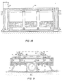
- the floor of the pontoon 92 is cleared to the maximum by providing the control cabin 96 on the side, as shown in FIG. 14.
- compartments are provided in the body thereof which can be ballasted with sand and water, the level of which is adjustable by means of pumps.
- the section of FIG. 14 shows such a structure.
- the jetty constituted by the pontoon 92 has considerable advantages over the floating mobile wharves commonly used. Indeed, during its use, the pontoon is rigorously fixed and is no longer subjected to the movement of waves, which facilitates all movement of vehicles on its floor. In the event of a storm, typhoon or other disturbance of the same type, the pontoon 92 can go up and be placed in dryness which completely ensures its safety. At its end closest to the ground, the pontoon 92 can be associated with a light gangway 97, which can be raised up the bridge for movement, as shown in FIG. 13.
- the maneuvers of descent and ascent of the crutches 2 are preferably controlled, in the pontoon of FIG. 1 as in that of FIG. 13, by a set of port and starboard hydraulic groups.
- Each set can, for example, comprise 3 or 4 hydraulic groups 98, FIG. 1, which are controlled from the control gateway 99 by electric cables 100.
- the relative movements of the pads and soles are controlled by solenoid valves applying or not applying the oil pressures supplied by the groups to the appropriate jacks. It is possible by acting on the various solenoid valves controlling the skates or the crutches to execute the various following movements. To move forward in a straight line, the crutches and skids on the port and starboard sides are operated simultaneously. To turn, as for tracked vehicles, one of the sets of crutches and pads is actuated while the other is at rest, the crutches raised for example. Note that the square section of the wells and the crutches also allows the crutches to be offset angularly by 90 °, so the longitudinal direction of the pads and soles for example to perform a final approach maneuver.
- the downward stroke of the pistons 42 of the jacks 22 of the crutches 2 can be controlled in order to distribute the loads or even on poorly leveled ground to compensate for local differences in levels.
- the shafts 1 can be replaced by means of hooking simpler crutches and the length of these can be reduced.
- the locking means shown in Figs. 4 and 5 and constituted by two pairs of pivoting arms linked together to form an articulated quadrilateral can then be replaced by simpler hooking devices, since these hooking means must make it possible to ensure the thrust of the crutches when they lift the load, which can be achieved by stops, and must keep the crutches suspended when they are retracted to advance the soles.
Landscapes
- Engineering & Computer Science (AREA)
- General Engineering & Computer Science (AREA)
- Civil Engineering (AREA)
- Structural Engineering (AREA)
- Mechanical Engineering (AREA)
- Mining & Mineral Resources (AREA)
- Life Sciences & Earth Sciences (AREA)
- General Life Sciences & Earth Sciences (AREA)
- Environmental & Geological Engineering (AREA)
- Paleontology (AREA)
- Architecture (AREA)
- Chemical & Material Sciences (AREA)
- Combustion & Propulsion (AREA)
- Transportation (AREA)
- Rehabilitation Tools (AREA)
- Footwear And Its Accessory, Manufacturing Method And Apparatuses (AREA)
- Bridges Or Land Bridges (AREA)
Claims (10)
Applications Claiming Priority (2)
| Application Number | Priority Date | Filing Date | Title |
|---|---|---|---|
| FR7734967A FR2409181A1 (fr) | 1977-11-16 | 1977-11-16 | Pontons echouables amphibies et moyens de deplacement a terre de lourdes charges |
| FR7734967 | 1977-11-16 |
Publications (2)
| Publication Number | Publication Date |
|---|---|
| EP0002146A1 EP0002146A1 (de) | 1979-05-30 |
| EP0002146B1 true EP0002146B1 (de) | 1981-09-02 |
Family
ID=9197852
Family Applications (1)
| Application Number | Title | Priority Date | Filing Date |
|---|---|---|---|
| EP78400164A Expired EP0002146B1 (de) | 1977-11-16 | 1978-11-08 | Mittel zum Versetzen von schweren Lasten über Land und/oder über einem unter Wasser stehenden oder nicht unter Wasser stehenden Strandteil |
Country Status (4)
| Country | Link |
|---|---|
| US (1) | US4308816A (de) |
| EP (1) | EP0002146B1 (de) |
| DE (1) | DE2861028D1 (de) |
| FR (1) | FR2409181A1 (de) |
Cited By (2)
| Publication number | Priority date | Publication date | Assignee | Title |
|---|---|---|---|---|
| WO2008006145A1 (en) * | 2006-07-11 | 2008-01-17 | Australian Sustainable Energy Corporation Pty Ltd | Wave energy converter |
| CN110983947A (zh) * | 2019-11-25 | 2020-04-10 | 浙江朱光波机械科技有限公司 | 高承载射流桥装置 |
Families Citing this family (8)
| Publication number | Priority date | Publication date | Assignee | Title |
|---|---|---|---|---|
| DE3525060A1 (de) * | 1985-01-26 | 1987-01-22 | Martin Schatta | Motor-segelschiff mit einer segel- und kraengungsautomatik insbesondere fuer eine autarke antriebs- sowie versorgungsenergieentnahme aus wind- und sonnenkraft |
| US4872524A (en) * | 1988-04-13 | 1989-10-10 | Oconnor Chadwell | Wheel-less walking dolly |
| US5439052A (en) * | 1994-01-29 | 1995-08-08 | Skinner; Earl F. | Pitless adapter valve for wells |
| AU2008336253A1 (en) * | 2007-12-12 | 2009-06-18 | Protean Energy Australia Pty Ltd | Improvements to wave energy converter |
| EP3384094A2 (de) * | 2015-12-04 | 2018-10-10 | Techlam S.A. | Einheit zum anschluss eines strukturellen elements einer offshore-plattform an eine aufnahmestruktur und zugehörige verwendungen |
| CN113047175A (zh) * | 2021-01-05 | 2021-06-29 | 中铁四局集团有限公司 | 一种钢箱梁组拼滑移平台及浮运方法 |
| CN114508036B (zh) * | 2022-01-06 | 2023-11-17 | 武汉船用机械有限责任公司 | 码头自升式乘客通廊装置 |
| CN116377870B (zh) * | 2023-03-27 | 2026-02-24 | 上海万移物流科技有限公司 | 一种内河桥梁安装方法及系统 |
Family Cites Families (16)
| Publication number | Priority date | Publication date | Assignee | Title |
|---|---|---|---|---|
| FR442451A (fr) * | 1911-04-19 | 1912-09-02 | Robert Alwyn Arnold Stephen Pi | Perfectionnements dans les échafaudages ou supports pour forage, tirage de mines, battage de pieux, pose de blocs et autres opérations sous-marines |
| US1222997A (en) * | 1916-07-13 | 1917-04-17 | Henry E Rottmer | Shackle or connecting-link. |
| FR502932A (fr) * | 1921-02-28 | 1920-05-29 | Augustin Georges Quelin | Véhicule entrainant des voies sur lesquelles il effectue son parcours |
| US1615055A (en) * | 1926-01-05 | 1927-01-18 | George E Turner | Hydraulic leveling and moving device |
| US2062657A (en) * | 1933-08-11 | 1936-12-01 | Sullivan Machinery Co | Coal mining machine |
| US2822878A (en) * | 1954-01-07 | 1958-02-11 | Paul E Corson | Walking tractor |
| FR1132144A (fr) * | 1954-10-26 | 1957-03-05 | Maschf Augsburg Nuernberg Ag | Dispositif pour déplacer de lourdes charges |
| US3114425A (en) * | 1960-08-12 | 1963-12-17 | Salem Tool Co | Stepper-type tramming support for mining equipment |
| US3135345A (en) * | 1961-02-06 | 1964-06-02 | Arthur W Scruggs | Multi-ped vehicle |
| US3249168A (en) * | 1962-12-29 | 1966-05-03 | Beteiligungs & Patentverw Gmbh | Excavating machine |
| FR1388757A (fr) * | 1963-11-18 | 1965-02-12 | De Long Corp | Dispositif mobile pour travaux maritimes |
| FR1416741A (fr) * | 1963-12-03 | 1965-11-05 | Werf Gusto V H A F Smulders Fa | Structure destinée à effectuer des travaux en eau profonde |
| US3345970A (en) * | 1966-03-28 | 1967-10-10 | Long Louis H De | Boat and barge combination |
| US3576225A (en) * | 1969-01-15 | 1971-04-27 | Hydranautics | Apparatus for moving multi-ton objects |
| JPS5121519B1 (de) * | 1971-05-28 | 1976-07-02 | ||
| GB1433830A (en) * | 1973-12-11 | 1976-04-28 | British Steel Corp | Load moving apparatus |
-
1977
- 1977-11-16 FR FR7734967A patent/FR2409181A1/fr active Granted
-
1978
- 1978-11-08 DE DE7878400164T patent/DE2861028D1/de not_active Expired
- 1978-11-08 EP EP78400164A patent/EP0002146B1/de not_active Expired
- 1978-11-09 US US05/959,107 patent/US4308816A/en not_active Expired - Lifetime
Cited By (4)
| Publication number | Priority date | Publication date | Assignee | Title |
|---|---|---|---|---|
| WO2008006145A1 (en) * | 2006-07-11 | 2008-01-17 | Australian Sustainable Energy Corporation Pty Ltd | Wave energy converter |
| AU2007272290B2 (en) * | 2006-07-11 | 2011-06-16 | Protean Energy Australia Pty Ltd | Wave energy converter |
| CN110983947A (zh) * | 2019-11-25 | 2020-04-10 | 浙江朱光波机械科技有限公司 | 高承载射流桥装置 |
| CN110983947B (zh) * | 2019-11-25 | 2021-07-02 | 深圳朱光波机械科技有限公司 | 高承载射流桥装置 |
Also Published As
| Publication number | Publication date |
|---|---|
| US4308816A (en) | 1982-01-05 |
| DE2861028D1 (en) | 1981-11-26 |
| EP0002146A1 (de) | 1979-05-30 |
| FR2409181A1 (fr) | 1979-06-15 |
| FR2409181B1 (de) | 1981-06-12 |
Similar Documents
| Publication | Publication Date | Title |
|---|---|---|
| EP0002146B1 (de) | Mittel zum Versetzen von schweren Lasten über Land und/oder über einem unter Wasser stehenden oder nicht unter Wasser stehenden Strandteil | |
| EP0090006B1 (de) | Schwimmende vorrichtung und verfahren zum heben und fördern von lasten | |
| WO2010127894A1 (fr) | Pont temporaire perfectionné | |
| FR2476585A1 (fr) | Coque d'embarcation | |
| KR102022805B1 (ko) | 수륙 양용 준설 바지선 | |
| NL8701856A (nl) | Werkwijze voor het manoeuvreren van een opbouwelement ten opzichte van een in water aangebrachte vaste constructie, werkwijze voor het bouwen van een bouwwerk en bouwwerk gebouwd volgens een dergelijke werkwijze. | |
| WO2004087495A2 (fr) | Dispositif et procede de stabilisation et de controle de la descente ou remontee d’une structure lourde entre la surface et le fond de la mer | |
| EP4121345B1 (de) | System zur handhabung von meeres- oder unterwasserdrohnen durch einen schwimmenden ponton mit einem abnehmbaren drohnenschnittstellenmodul, angepasstes schiff | |
| EP0169781B1 (de) | Vorrichtung für das Anbordnehmen von Wasserfahrzeugen auf Schiffe | |
| WO2007012757A1 (fr) | Système de transport d'une travure par un véhicule routier pouvant être transformé en véhicule amphibie pour permettre à tout véhicule routier de franchir une brèche sèche ou remplie d'eau | |
| EP2836421A1 (de) | Modul zur herstellung einer ro-ro-überkreuzungsvorrichtung | |
| CA1281555C (fr) | Plate-forme semi-submersible, notamment pour la recherche et/ou l'exploitation de gisements sous- marins en mers froides | |
| EP1204806B1 (de) | Schwimmende träger mit einem zentralhohlraum, der aus einer vielzahl von fächern besteht | |
| FR2755661A1 (fr) | Dispositif de mise hors de l'eau de bateaux | |
| NL1023320C2 (nl) | De uitvinding heeft betrekking op een methode voor fabricage, installatie en verwijderen van een offshore platform. | |
| EP4065462B1 (de) | Antriebsflügel eines sich bewegenden fahrzeugs und sich bewegendes fahrzeug mit einem solchen antriebsflügel | |
| FR2645827A1 (fr) | Plate-forme marine formee d'une pluralite d'elements modulaires pour le stockage de produits et pour l'amarrage et le chargement directs des navires, et procede d'installation, de demontage et de reinstallation en un autre endroit de cette plate-forme | |
| FR2541648A1 (fr) | Structure de multicoque a nacelle articulee permettant le redressement apres chavirage | |
| FR3047229A1 (fr) | Dispositif de deplacement et de mise a terre d'un navire | |
| EP0646522B1 (de) | Tragstruktur für ein Schiff | |
| US6901877B1 (en) | Foam block replacement barge | |
| EP4540129B1 (de) | Containerschiff, das mit einem umladesystem ausgestattet ist | |
| FR3032681A1 (fr) | Structure de support et d'ancrage d'eolienne maritime du type tour treillis et procede de remorquage et depose en mer | |
| EP0332500B1 (de) | Fahrzeug für Unterhaltsarbeiten an Oberflächen von Unterwasserteilen von schwimmenden Strukturen | |
| FR2682701A1 (fr) | Caisson flottant. |
Legal Events
| Date | Code | Title | Description |
|---|---|---|---|
| PUAI | Public reference made under article 153(3) epc to a published international application that has entered the european phase |
Free format text: ORIGINAL CODE: 0009012 |
|
| AK | Designated contracting states |
Designated state(s): BE DE GB NL SE |
|
| 17P | Request for examination filed | ||
| GRAA | (expected) grant |
Free format text: ORIGINAL CODE: 0009210 |
|
| AK | Designated contracting states |
Designated state(s): BE DE GB NL SE |
|
| PG25 | Lapsed in a contracting state [announced via postgrant information from national office to epo] |
Ref country code: BE Effective date: 19811108 |
|
| REF | Corresponds to: |
Ref document number: 2861028 Country of ref document: DE Date of ref document: 19811126 |
|
| PGFP | Annual fee paid to national office [announced via postgrant information from national office to epo] |
Ref country code: NL Payment date: 19811130 Year of fee payment: 4 |
|
| PG25 | Lapsed in a contracting state [announced via postgrant information from national office to epo] |
Ref country code: SE Effective date: 19821109 |
|
| PGFP | Annual fee paid to national office [announced via postgrant information from national office to epo] |
Ref country code: DE Payment date: 19821231 Year of fee payment: 5 |
|
| PG25 | Lapsed in a contracting state [announced via postgrant information from national office to epo] |
Ref country code: NL Effective date: 19830601 |
|
| NLV4 | Nl: lapsed or anulled due to non-payment of the annual fee | ||
| GBPC | Gb: european patent ceased through non-payment of renewal fee | ||
| PG25 | Lapsed in a contracting state [announced via postgrant information from national office to epo] |
Ref country code: DE Effective date: 19840801 |
|
| PG25 | Lapsed in a contracting state [announced via postgrant information from national office to epo] |
Ref country code: GB Effective date: 19881117 |
|
| EUG | Se: european patent has lapsed |
Ref document number: 78400164.6 Effective date: 19820610 |
|
| PLBE | No opposition filed within time limit |
Free format text: ORIGINAL CODE: 0009261 |
|
| STAA | Information on the status of an ep patent application or granted ep patent |
Free format text: STATUS: NO OPPOSITION FILED WITHIN TIME LIMIT |