EP0001458A1 - Anzeigetrommel mit beschrifteten Tafeln - Google Patents
Anzeigetrommel mit beschrifteten Tafeln Download PDFInfo
- Publication number
- EP0001458A1 EP0001458A1 EP78200168A EP78200168A EP0001458A1 EP 0001458 A1 EP0001458 A1 EP 0001458A1 EP 78200168 A EP78200168 A EP 78200168A EP 78200168 A EP78200168 A EP 78200168A EP 0001458 A1 EP0001458 A1 EP 0001458A1
- Authority
- EP
- European Patent Office
- Prior art keywords
- slots
- disc
- holes
- slot
- disk
- Prior art date
- Legal status (The legal status is an assumption and is not a legal conclusion. Google has not performed a legal analysis and makes no representation as to the accuracy of the status listed.)
- Withdrawn
Links
- 238000003780 insertion Methods 0.000 abstract description 2
- 230000037431 insertion Effects 0.000 abstract description 2
- 238000009434 installation Methods 0.000 abstract 1
- 238000004519 manufacturing process Methods 0.000 description 2
- 238000007792 addition Methods 0.000 description 1
- 230000005489 elastic deformation Effects 0.000 description 1
- 239000013013 elastic material Substances 0.000 description 1
- 239000000463 material Substances 0.000 description 1
- 230000008719 thickening Effects 0.000 description 1
Images
Classifications
-
- G—PHYSICS
- G09—EDUCATION; CRYPTOGRAPHY; DISPLAY; ADVERTISING; SEALS
- G09F—DISPLAYING; ADVERTISING; SIGNS; LABELS OR NAME-PLATES; SEALS
- G09F11/00—Indicating arrangements for variable information in which the complete information is permanently attached to a movable support which brings it to the display position
- G09F11/02—Indicating arrangements for variable information in which the complete information is permanently attached to a movable support which brings it to the display position the display elements being secured to rotating members, e.g. drums, spindles
- G09F11/04—Indicating arrangements for variable information in which the complete information is permanently attached to a movable support which brings it to the display position the display elements being secured to rotating members, e.g. drums, spindles the elements being secured to rotating discs
Definitions
- the present invention relates to a display drum, which consists of exchangeable labeled panels and at least two disks rotatable about a common horizontal axis. These disks are circular, run parallel and have ring-shaped bearing points, in which the said plates are each pivoted along an axis parallel to the said axis in such a way that when the drum rotates in the manner of the pages of a book one after the other Fold down into a lower display position.
- Such drums have been known for many years as essential components of detectors for displaying timetables, stock exchange prices, sports results and other information. There are various options for designing the axis on which the panels are mounted.
- each table has at least one of its edges serving for its storage, each formed by a cutout lying completely inside the table, and each of the mentioned bearing points consists of a round hole with one on the edge of the disc leading slot through which said web belonging to the panel to be stored can be inserted into and removed from the hole.
- a disadvantage of this known drum is the fact that very great demands must be placed on the mutual coordination of the width of the slots and the thickness of the panels, because in order to prevent the webs located in the bearing holes from accidentally entering into during the normal rotation of the drum
- the slots In order to avoid these holes leading to the outside, the slots must be a little narrower than the thickness of the panels, so that the webs can only be inserted into and removed from the holes with elastic deformation of the slots.
- the panels In order to be able to accommodate the largest possible number of panels on the smallest possible drum, the panels should be as thin as possible, which leads to difficulties and therefore high costs, regardless of the slot production method.
- the selected thickness of the sheets must be adhered to very precisely, which can increase the cost of the material used for this.
- the object is now achieved to provide a display drum of the type described, in which the width of the slots can be selected to be greater than the thickness of the panels, but in which no additions have to be made to the webs. It affects a display drum according to the type and state of the art described, which is characterized by a ring-shaped closure device connected to each disc and running parallel to the relevant disc in the area of the slots mentioned, which is arranged concentrically with respect to the disc and can be rotated coaxially and which Slits of the disc are covered.
- This closure device thus closes the entrances to the holes and has at least one slot which, in certain positions considered in relation to the disk, lies above one of the slots in the disk and thus releases access to the associated hole. The whole is arranged in such a way that by rotating the closure device relative to the associated pane, the slots used to insert and remove the plates into the holes or out of the holes in the pane can be opened and closed.
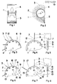
- Figures 1 and 2 each show a basic front and side view of a display drum to which the invention relates.
- FIGS. 3, 4 and 5 relate to the first exemplary embodiment, with FIGS. 3 and 4 each showing a partially sectioned side view and FIG. 5 representing a cross section through the pane relating to FIG. 4.
- FIGS. 3 and 4 each showing a partially sectioned side view
- FIG. 5 representing a cross section through the pane relating to FIG. 4.
- all slots are closed; on the other hand, one of the slots is open in FIG.
- FIGS. 6, 7 and 8 relate to the second exemplary embodiment and correspond to FIGS. 3, 4 and 5 the difference that not only 1 slot but all slots are open in FIG. 6.
- the drum shown in Figures 1 and 2 consists of two circular disks 1 which are rigidly connected to one another and are rotatably mounted about an axis 2. If the drum is rotated gradually in the direction of the arrow in a manner not shown, the plates 3 pivotably mounted in these disks first reach an upper display position 4, where they are held in a manner not shown, and then fall into a lower display position 5. The two in the The top and bottom panels together show a certain sign.
- FIGS. 4 and 5 the detail from a table 3 is shown, from which the type of storage of the table can be seen.
- a web 7 is formed by a cutout 8, which is provided in the vicinity of the edge and lies completely inside the panel, with which the panel is pivotably mounted in the pane 1.
- the disc 1 has round holes 6 for this purpose.
- a slot 9 leads from each of these holes to the edge of the disk 1, as a result of which the web 7 of a panel 3 can be inserted into the associated hole 6.
- An annular closure device 11 is placed around the edge of the disk 1.
- This ring has a U-shaped profile and is dimensioned such that the legs of the profile lie on both sides of the side surfaces of the disc 1 and cover the slots 9 while leaving the holes free.
- the webs 7 are thus caught in the holes 6, but can move freely therein.
- the one made of elastic Material existing ring 11 is rotatable on the disc and lockable in a manner not shown. It has a continuous slot 12 at one point, thanks to which it can be attached to the pane.
- This slot 12 is dimensioned to such an extent that it is at least as wide as the slots 9.
- the hole 6 in question is freely accessible for the introduction of a web 7 and thus for the insertion of a board 3 into the drum or for the relevant removal. Any plates of the drum can be used alternately. be replaced when the slot 12 is placed over the slot 9 in question.
- the ring 11 is brought into a position in which the slot 12 is between two slots 9, and the ring is then fixed in a manner not shown. In this position of the ring shown in Figure 3, the exit of all holes 7 is closed. This is the operating position in which the drum is used for display.
- the closure device consists of a flat ring 13 which is attached to one side of the disc 1 and covers both holes and slots 9.
- the ring 13 is connected to the disc 1 at three points regularly arranged with respect to the axis of rotation 2, only one of which is shown in the figures, in such a way that the ring 13 can be rotated relative to the disc 1 within two extreme positions . This is achieved in that at three points lying between the holes 6 and the axis 2 there is an elongated one, with respect to the axis 2 tangential running hole 14 is attached in the ring 13, which is penetrated by a screw 15 inserted into this disk 1, preferably a fitting screw.
- the ring 13 each has an elongated hole 17 at the inner end of these slots, which is dimensioned, shaped and fitted in such a position that the associated hole 6 in all possible positions of the ring 13 with respect to the disk 1 released from the ring and thus the storage of the panels 3 is in no way hindered by the ring.
Landscapes
- Physics & Mathematics (AREA)
- General Physics & Mathematics (AREA)
- Engineering & Computer Science (AREA)
- Theoretical Computer Science (AREA)
- Displays For Variable Information Using Movable Means (AREA)
- Devices For Indicating Variable Information By Combining Individual Elements (AREA)
Applications Claiming Priority (2)
| Application Number | Priority Date | Filing Date | Title |
|---|---|---|---|
| CH12266/77 | 1977-10-07 | ||
| CH1226677A CH619553A5 (enExample) | 1977-10-07 | 1977-10-07 |
Publications (1)
| Publication Number | Publication Date |
|---|---|
| EP0001458A1 true EP0001458A1 (de) | 1979-04-18 |
Family
ID=4381415
Family Applications (1)
| Application Number | Title | Priority Date | Filing Date |
|---|---|---|---|
| EP78200168A Withdrawn EP0001458A1 (de) | 1977-10-07 | 1978-08-30 | Anzeigetrommel mit beschrifteten Tafeln |
Country Status (2)
| Country | Link |
|---|---|
| EP (1) | EP0001458A1 (enExample) |
| CH (1) | CH619553A5 (enExample) |
Citations (4)
| Publication number | Priority date | Publication date | Assignee | Title |
|---|---|---|---|---|
| DE536782C (de) * | 1931-03-20 | 1933-04-08 | Julius Isidor Berkowitz | Reklameapparat mit schwenkbaren Schildern aus Karton |
| CH176168A (de) * | 1933-06-03 | 1935-03-31 | Hayn Fritz | Reklameapparat mit auswechselbaren, schwenkbaren Schildern. |
| CH460592A (de) * | 1967-12-28 | 1968-07-31 | Autophon Ag | Anzeigeeinrichtung mit beschrifteten Tafeln |
| DE2348480B1 (de) * | 1973-09-26 | 1974-10-24 | Krone Gmbh | Anzeigeeinrichtung mit beidseitig beschrifteten Klapptafeln |
-
1977
- 1977-10-07 CH CH1226677A patent/CH619553A5/de not_active IP Right Cessation
-
1978
- 1978-08-30 EP EP78200168A patent/EP0001458A1/de not_active Withdrawn
Patent Citations (4)
| Publication number | Priority date | Publication date | Assignee | Title |
|---|---|---|---|---|
| DE536782C (de) * | 1931-03-20 | 1933-04-08 | Julius Isidor Berkowitz | Reklameapparat mit schwenkbaren Schildern aus Karton |
| CH176168A (de) * | 1933-06-03 | 1935-03-31 | Hayn Fritz | Reklameapparat mit auswechselbaren, schwenkbaren Schildern. |
| CH460592A (de) * | 1967-12-28 | 1968-07-31 | Autophon Ag | Anzeigeeinrichtung mit beschrifteten Tafeln |
| DE2348480B1 (de) * | 1973-09-26 | 1974-10-24 | Krone Gmbh | Anzeigeeinrichtung mit beidseitig beschrifteten Klapptafeln |
Also Published As
| Publication number | Publication date |
|---|---|
| CH619553A5 (enExample) | 1980-09-30 |
Similar Documents
| Publication | Publication Date | Title |
|---|---|---|
| DE3044806C2 (enExample) | ||
| DE1172348B (de) | Mehrstellungswaehlschalter | |
| CH641533A5 (de) | Vorrichtung zur loesbaren befestigung eines flexiblen teils an einem starren teil, insbesondere einer blache an einem fahrzeug. | |
| DE2537901A1 (de) | Ausstellvorrichtung fuer kassetten und aehnliche artikel | |
| DE3532169A1 (de) | Filter | |
| DE2156050B2 (de) | Ausstellungsständer | |
| DE700786C (de) | Verriegelungsvorrichtung fuer Fenster | |
| EP0001458A1 (de) | Anzeigetrommel mit beschrifteten Tafeln | |
| DE2604898C3 (de) | Anzeigetrommel mit auswechselbaren beschrifteten Tafeln | |
| DE3208314C2 (enExample) | ||
| DE102020105504A1 (de) | Mausvorrichtung und Scrollradmodul | |
| DE10047954A1 (de) | Rahmenstruktur zum einbauen von Einschubplatten | |
| DE1927752A1 (de) | Behaelter-Kassetten-Einheit zur Aufnahme eines Bandes,vorzugsweise eines Filmbandes | |
| DE69609556T2 (de) | Vorrichtung zur Anzeige von Abbildungen, Texten und dergleichen | |
| DE2429358B2 (de) | Kassette für eine Anzahl von Informationskarten | |
| DE3526240A1 (de) | Schafthalte- und -antriebsvorrichtung | |
| DE60006303T2 (de) | Lagerdrehbodengestell | |
| DE29607040U1 (de) | Anzeigevorrichtung | |
| EP1015257A1 (de) | Einrichtung zum umblätterbaren ablegen von flachen gegenständen, insbesondere compact-discs | |
| DE3615555A1 (de) | Trommel fuer waschmaschinen | |
| DE29712288U1 (de) | Vorrichtung zum Waschen von Fahrzeugen | |
| DE2165477A1 (de) | Elektronisches Planimeter | |
| DE2417858A1 (de) | Registriergeraet | |
| CH673984A5 (enExample) | ||
| DE2624275B1 (de) | Sicherungsvorrichtung |
Legal Events
| Date | Code | Title | Description |
|---|---|---|---|
| PUAI | Public reference made under article 153(3) epc to a published international application that has entered the european phase |
Free format text: ORIGINAL CODE: 0009012 |
|
| AK | Designated contracting states |
Designated state(s): CH DE FR |
|
| STAA | Information on the status of an ep patent application or granted ep patent |
Free format text: STATUS: THE APPLICATION IS DEEMED TO BE WITHDRAWN |
|
| 18D | Application deemed to be withdrawn | ||
| RIN1 | Information on inventor provided before grant (corrected) |
Inventor name: HEINZL, LUDWIG |