EP0001095B1 - Dispositif d'ancrage et/ou de liaison pour éléments en béton ou en matérian similaire - Google Patents
Dispositif d'ancrage et/ou de liaison pour éléments en béton ou en matérian similaire Download PDFInfo
- Publication number
- EP0001095B1 EP0001095B1 EP19780100797 EP78100797A EP0001095B1 EP 0001095 B1 EP0001095 B1 EP 0001095B1 EP 19780100797 EP19780100797 EP 19780100797 EP 78100797 A EP78100797 A EP 78100797A EP 0001095 B1 EP0001095 B1 EP 0001095B1
- Authority
- EP
- European Patent Office
- Prior art keywords
- anchoring
- way
- friction welding
- bolt
- sleeve
- Prior art date
- Legal status (The legal status is an assumption and is not a legal conclusion. Google has not performed a legal analysis and makes no representation as to the accuracy of the status listed.)
- Expired
Links
- 238000004873 anchoring Methods 0.000 title claims description 64
- 238000003466 welding Methods 0.000 claims description 62
- 229910001294 Reinforcing steel Inorganic materials 0.000 claims description 5
- 239000002184 metal Substances 0.000 claims description 3
- 229910000831 Steel Inorganic materials 0.000 claims description 2
- 239000010959 steel Substances 0.000 claims description 2
- 229910000975 Carbon steel Inorganic materials 0.000 claims 1
- 239000010962 carbon steel Substances 0.000 claims 1
- 239000000463 material Substances 0.000 description 11
- 229910001220 stainless steel Inorganic materials 0.000 description 10
- 239000010935 stainless steel Substances 0.000 description 8
- 229910000746 Structural steel Inorganic materials 0.000 description 6
- 238000010438 heat treatment Methods 0.000 description 3
- 238000004519 manufacturing process Methods 0.000 description 3
- 241000209035 Ilex Species 0.000 description 2
- 230000004888 barrier function Effects 0.000 description 2
- 239000000969 carrier Substances 0.000 description 2
- 238000000034 method Methods 0.000 description 2
- XLYOFNOQVPJJNP-UHFFFAOYSA-N water Substances O XLYOFNOQVPJJNP-UHFFFAOYSA-N 0.000 description 2
- 235000001674 Agaricus brunnescens Nutrition 0.000 description 1
- OKTJSMMVPCPJKN-UHFFFAOYSA-N Carbon Chemical compound [C] OKTJSMMVPCPJKN-UHFFFAOYSA-N 0.000 description 1
- 241000701193 Mutellina purpurea Species 0.000 description 1
- 230000006978 adaptation Effects 0.000 description 1
- 229910052799 carbon Inorganic materials 0.000 description 1
- 210000000078 claw Anatomy 0.000 description 1
- 239000002131 composite material Substances 0.000 description 1
- 238000010276 construction Methods 0.000 description 1
- 230000013011 mating Effects 0.000 description 1
- 239000010970 precious metal Substances 0.000 description 1
- 239000007858 starting material Substances 0.000 description 1
Images

Classifications
-
- E—FIXED CONSTRUCTIONS
- E04—BUILDING
- E04G—SCAFFOLDING; FORMS; SHUTTERING; BUILDING IMPLEMENTS OR AIDS, OR THEIR USE; HANDLING BUILDING MATERIALS ON THE SITE; REPAIRING, BREAKING-UP OR OTHER WORK ON EXISTING BUILDINGS
- E04G21/00—Preparing, conveying, or working-up building materials or building elements in situ; Other devices or measures for constructional work
- E04G21/14—Conveying or assembling building elements
- E04G21/142—Means in or on the elements for connecting same to handling apparatus
-
- E—FIXED CONSTRUCTIONS
- E04—BUILDING
- E04B—GENERAL BUILDING CONSTRUCTIONS; WALLS, e.g. PARTITIONS; ROOFS; FLOORS; CEILINGS; INSULATION OR OTHER PROTECTION OF BUILDINGS
- E04B1/00—Constructions in general; Structures which are not restricted either to walls, e.g. partitions, or floors or ceilings or roofs
- E04B1/38—Connections for building structures in general
- E04B1/41—Connecting devices specially adapted for embedding in concrete or masonry
- E04B1/4114—Elements with sockets
- E04B1/4121—Elements with sockets with internal threads or non-adjustable captive nuts
-
- E—FIXED CONSTRUCTIONS
- E04—BUILDING
- E04B—GENERAL BUILDING CONSTRUCTIONS; WALLS, e.g. PARTITIONS; ROOFS; FLOORS; CEILINGS; INSULATION OR OTHER PROTECTION OF BUILDINGS
- E04B1/00—Constructions in general; Structures which are not restricted either to walls, e.g. partitions, or floors or ceilings or roofs
- E04B1/38—Connections for building structures in general
- E04B1/41—Connecting devices specially adapted for embedding in concrete or masonry
- E04B1/4157—Longitudinally-externally threaded elements extending from the concrete or masonry, e.g. anchoring bolt with embedded head
Definitions
- the invention relates to an anchor and / or connecting device for concrete parts or the like, which comprises a connection part protruding from the concrete part and an anchoring part embedded in the concrete part.
- the anchoring part has the task of improving the hold of the device in the concrete part, while the connecting part is accessible on the outside of the concrete part and can be connected to a lifting tool or a connector.
- the connection with a lifting tool is selected when transporting the concrete part, while the connector is used to create a connection between two concrete parts on site.
- the device consisting of the connecting part and the anchoring part remains embedded in the concrete part. The device is therefore a mass product which is to be manufactured very cheaply and yet has to have a sufficient load-bearing capacity.
- connection part is exposed at least in the area of its star side on the concrete part. If the device is used to connect concrete parts, this area is exposed to atmospheric influences.
- the cheap concrete and structural steels fail for such a device and it is necessary to switch to stainless steels or refined surfaces. These stainless steels or refined parts are, however, considerably more expensive and therefore involve a very considerable increase in the cost of such a device. This configuration is unsatisfactory, especially when most of the device is embedded in the concrete part.
- the connecting part and the anchoring part are formed as separate parts which are firmly and permanently connected to one another by means of friction welding, the connecting part made of stainless steel or of a metal with a refined surface and the anchoring part made of construction or Reinforcing steel exists.
- Friction welding is a work process that is easy to control and can be carried out much faster than the usual welds.
- the subdivision of the device into a connecting part and an anchoring part allows an optimal material adaptation.
- the connecting part consists of stainless steel or with a refined surface and the anchoring part consists of concrete or structural steel with an unprocessed surface.
- This design is sufficient, since only the connector is exposed to atmospheric influences. As a result, considerable cost savings can be achieved by reducing the proportion of stainless steel or of refined material.
- the anchoring part of the device embedded in the concrete part can be made of cheap concrete or structural steel.
- anchor and / or connecting devices the parts of which are made of different materials, can also be produced in this way.
- connection part is designed as a bolt with a threaded part and that the bolt-free end of the bolt is connected by friction welding to an anchor plate as an anchoring part.
- the bolt with the threaded part can be produced cheaply in known operations, the anchor plate being able to have a rectangular, square or round cross section.
- the friction welding is carried out simply by a part, e.g. the bolt on the other part, e.g. the anchor plate, is under pressure and is set into rapid rotary movements. After sufficient heating, the rotary movement is ended and the parts are pressed against one another while increasing the pressure.
- the cost of materials for expensive stainless steel or refined metal can be reduced even more with such an anchor and / or connecting device in that the threaded part itself is connected to the bolt as a separate part by means of friction welding.
- the threaded part remains partially free in this device and is used to connect a lifting tool or a connector with a threaded hole.
- only the threaded part needs to be made of stainless steel, or must be provided with a finished surface alone. All other parts can be made of cheap structural or reinforcing steel.
- the device can also be designed such that the connecting part is designed as a bolt with an upset, enlarged cross-section joint part and that the other end of the bolt is connected by friction welding to an anchor plate as an anchoring part.
- the joint part is exposed in the concrete part and is used to link a joint counterpart, preferably a lifting tool.
- the device according to the invention is designed so that the connecting part is designed as a sleeve which is provided with an internal thread on at least one side and is closed at the other end by means of friction welding with an anchor plate as an anchoring part.
- the material expenditure of stainless steel can be reduced to a minimum by connecting the sleeve without internal thread by means of friction welding to a separate threaded sleeve.
- connection part is designed as a pot-like sleeve with a blind bore and internal thread, and that at least one bolt is attached to the bottom of this pot-like sleeve by means of friction welding, the free end of which being compressed is enlarged in cross section.
- the pot-like sleeve can then be produced from a section of a round material in normal operations. In this case, a cheap bolt with an upset head is used as the anchoring part, which is quickly connected to the sleeve without affecting the strength.
- the anchor and / or connecting device can also be designed for even greater load capacities.
- the connecting part is designed as a fastening plate, at the rear of which at least one bolt is attached as an anchoring part by means of friction welding and that the free end of this bolt is enlarged by upsetting or is connected to an anchor plate by means of friction welding. Beams, struts or the like can then be welded to the fastening plate, which is preferably inserted flush with the top side into the concrete part.
- This welding process on site can be dispensed with if the design is such that the connecting part is designed as a mounting plate with bores and that a sleeve with an internal thread or a pot-like sleeve with a blind bore and an internal thread is attached to the rear of each bore by means of friction welding is.
- the carriers, struts or the like can then be screwed directly to the anchor and / or connecting device.
- the sleeve can be closed at the free end by means of friction welding with an anchor plate.
- at least one bolt with an upset, enlarged end with a cross section is attached to the bottom of the sleeve as an anchoring part by means of friction welding.
- several bolts can also be attached to a sleeve with a large cross-section in this way.
- a common anchor plate can then be provided for all bolts.
- the hold of the anchoring part in the concrete part can be significantly improved in such a composite anchor and / or connecting device in that the bolt or sleeve is provided with an external thread.
- This additional external thread can be applied without any significant manufacturing effort in the manufacture of the anchoring parts.
- a section of a threaded rod can also be used as the anchoring part.
- An anchor device is advantageous for claw-like lifting tools, which is characterized in that the connecting part is designed as a ball.
- This ball as a connecting part provides an excellent articulated connection between the anchor device and the lifting tool.
- the upset end of the anchoring part can also be designed such that the free end of the bolt or the sleeve are provided with mushroom-like upsets. These mushroom-like upsets provide a large additional abutment surface for the anchoring part.
- the connecting part commercially available parts can also be used if, according to a further embodiment, it is provided that the connecting part is designed as a nut with a thread length which corresponds to at least 1.5 times the thread diameter.
- the anchoring parts can be produced from commercially available parts in a simple manner if the design of the anchor and / or connecting device is selected such that a section of a threaded rod is used as an anchoring part, which is connected to the nut by means of friction welding.
- the ends of two anchoring parts are firmly and permanently connected to one another by means of friction welding to form a double anchor and that the remaining ends of the anchoring parts are each connected to a connecting part.
- the connection point of the two anchoring parts of the double anchor then forms a kind of water barrier.
- a double anchor for connecting a lifting tool with a threaded part is characterized in that two sections of a threaded rod are connected to one another as anchoring parts of a double anchor and that nuts with an enlarged thread length are screwed onto the free ends of the double anchor as connecting parts.
- the nuts cannot be turned, e.g. fixed by caulking, welding or the like on the double anchor.
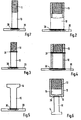
- the device according to FIG. 1 consists of a bolt 10 which has been cut to length from a round material.
- One end of this bolt is provided with a threaded part 11 in a known manner.
- the other end of the bolt 10 is firmly and permanently connected to the anchor plate 20 by means of friction welding, as the welding area 30 indicates. This area extends over limited zones, so that during this heating and welding there are no stress fields in the material which could impair the strength of the device. This is particularly important when carbon-rich reinforcing steel or structural steel is used as the starting material.
- the bolt 10 can consist of stainless steel and can be connected to a cheap anchor plate 20 made of concrete or structural steel.
- This anchor plate 20 in a rectangular, square or round cross section is a simple and inexpensive to produce stamped part.
- the threaded part 11 receives, n lifting tool or a mating connector, which are provided with a corresponding threaded hole.
- the connecting part for the lifting tool or the connector can also be designed as a sleeve 12, which is closed on one side with the anchor plate 20 by means of friction welding.
- the free end is provided with an internal thread 13 which extends at least over part of the length of the sleeve 12.
- the welding area 30 extends only over limited zones of the sleeve 12 and the anchor plate 20.
- FIGS. 3 and 4 show, the expenditure of stainless steel can be considerably reduced in the devices of FIGS. 1 and 2, and the device can be made cheaper accordingly, that the bolt 10 as a threadless section by means of a welding area 31 produced by friction welding with a separate threaded part 11 is connected or that the sleeve 12 is connected as a pipe section to a section of a threaded sleeve by means of friction welding.
- the free end of the bolt 10 is formed by upsetting into a head which is enlarged in cross section and which can serve as a joint part 14 for a joint counterpart of a lifting tool.
- the sleeve 12 in the device according to FIG. 6 is made from a full section of a round material. After the blind bore 15 has been introduced, the internal thread 13 is introduced. On the bottom 16 of the sleeve 12, a bolt 10 with an upset head can be attached as an anchoring part by means of friction welding, as is shown in the welding area 30. These bolts 10 can be connected to a common anchor plate, these connections also being produced by friction welding.
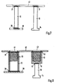
- a fastening plate 40 is used as the connecting part, on the rear side of which a plurality of bolts 10 are attached as anchoring parts.
- the bolts 10 are attached to the fastening plate 40 by means of friction welding, as the welding areas 31 show.
- the free ends of the bolts 10 can be connected to individual or a common anchor plate 20, as the welding area 30 shows.
- the free ends of the bolts 10 can also only be upset and form enlarged heads.
- Carriers, struts or the like can be welded onto the upper side of the fastening plate 40.
- the fastening plate 40 can also have bores 41 and 42.
- a sleeve 12 is attached to the back of the fastening plate 40 by means of friction welding, as the welding areas 31 indicate.
- the sleeve 12 can partially with a Internal thread 13 may be provided, as shown in the left part of the drawing. A threaded part of a screw or the like can be screwed directly into this internal thread 13 through the bore 41 of the fastening plate 40.
- the sleeve 12 is closed by the anchor plate 20, which is also attached by friction welding, as the welding area 30 indicates.
- the sleeve 12 can also be cup-shaped, as shown in the right part of the drawing. A threaded part of a screw or the like can be screwed directly into the internal thread 13 through the bore 42 of the fastening plate 40.
- a bolt 10 with an upset head is attached as an anchoring part 14, specifically by means of friction welding, as is indicated with the welding area 30.
- the bolt 10 can also be closed with an anchor plate 20.
- the bolt 10 and this anchor plate 20 are connected to one another again by means of friction welding.
- a plurality of bolts 10 with individual anchor plates or a common anchor plate can also be attached to the bottom 16 of the sleeve 12.
- an anchor device for a lifting tool with claws can also consist of a ball 17 with a welded-on bolt 10.
- the ball 17 provides an excellent articulated connection between the lifting tool and the anchor device.
- the ball 17 is connected to the bolt 10 by means of friction welding, as the welding area 30 indicates.
- the bolt 10 is provided on its outside with a coarse thread 18, which improves the anchoring of this anchoring part in the concrete part.
- the anchor and / or connecting device shown in FIG. 10 uses a section 22 of a threaded rod as the anchoring part, which is connected by means of friction welding to a nut 21 as a connecting part, as can be seen in the welding area 30.
- This nut 21 has a thread length which corresponds to at least 1.5 times the thread diameter in order to achieve sufficient load-bearing capacity.
- a threaded sleeve 12 ' is connected to a sleeve 12 as a connecting part by means of friction welding (welding area 30).
- the sleeve 12 can have a mushroom-like upsetting 23 at the free end.
- the sleeve 12 is e.g. heated by friction at both ends in one operation and then connected to the threaded sleeve 12 'via the welding region 30. At the same time, the other end of the sleeve 12 can be compressed.
- FIG. 12 shows an anchor and / or connecting device designed as a double anchor.
- the two sections 22 and 22 'of a threaded rod are connected to one another by means of friction welding, the welding area 30 forming a kind of water barrier.
- the two nuts 21 and 21' are screwed onto the anchoring part thus assembled as a connecting part.
- the welds 24 and 24 ' show, the nuts 21 and 21' are fixed non-rotatably on the sections 22 and 22 '. This determination can also be made by means of a known; Caulking.
- the larger anchoring part can consist of cheap structural or reinforcing steel or can be provided with an unfinished surface.
- the connection of the parts by friction welding is quick and cheap to produce and does not have the disadvantages of known welded connections.
- the anchoring can be improved further in that the cup-like sleeve is heated by friction at the closed end and is enlarged in cross-section by upsetting. This results in an enlarged anchoring flange to which the bolt with the compressed free end is then attached by means of friction welding.
- the joint part 14 can be designed in various forms. This is determined solely by the shape of the upsetting tool.
- This hinge part 14 can e.g. as a ball, as a truncated cone, as a mushroom or as a hexagon nut or the like.
Landscapes
- Engineering & Computer Science (AREA)
- Architecture (AREA)
- Civil Engineering (AREA)
- Structural Engineering (AREA)
- Physics & Mathematics (AREA)
- Electromagnetism (AREA)
- Mechanical Engineering (AREA)
- Joining Of Building Structures In Genera (AREA)
Claims (13)
Applications Claiming Priority (2)
| Application Number | Priority Date | Filing Date | Title |
|---|---|---|---|
| DE2739879 | 1977-09-05 | ||
| DE19772739879 DE2739879A1 (de) | 1977-09-05 | 1977-09-05 | Anker- und/oder verbindungsvorrichtung, insbesondere fuer betonteil o.dgl. |
Publications (3)
| Publication Number | Publication Date |
|---|---|
| EP0001095A2 EP0001095A2 (fr) | 1979-03-21 |
| EP0001095A3 EP0001095A3 (en) | 1979-04-04 |
| EP0001095B1 true EP0001095B1 (fr) | 1980-12-10 |
Family
ID=6018119
Family Applications (1)
| Application Number | Title | Priority Date | Filing Date |
|---|---|---|---|
| EP19780100797 Expired EP0001095B1 (fr) | 1977-09-05 | 1978-08-31 | Dispositif d'ancrage et/ou de liaison pour éléments en béton ou en matérian similaire |
Country Status (2)
| Country | Link |
|---|---|
| EP (1) | EP0001095B1 (fr) |
| DE (1) | DE2739879A1 (fr) |
Families Citing this family (20)
| Publication number | Priority date | Publication date | Assignee | Title |
|---|---|---|---|---|
| EP0019922A1 (fr) * | 1979-06-05 | 1980-12-10 | Heinz G. Riss | Dispositif d'ancrage et de manutention à pied élargi et tête de levage |
| DE3017840C2 (de) * | 1980-05-09 | 1984-05-17 | Kaiser-Omnia Bausysteme Gmbh & Co, 6000 Frankfurt | Bleibende Schalung für eine Betondecke und Anker hierfür |
| DE3107506A1 (de) * | 1981-02-27 | 1982-09-16 | Kraftwerk Union AG, 4330 Mülheim | Verankerungselement |
| DE3338762A1 (de) * | 1983-10-26 | 1985-05-09 | Winfried Dipl.-Ing. 6365 Rosbach Schnabel | Verankerungen von stahlbauteilen durch schraubverbindungen im beton |
| EP0158944A3 (fr) * | 1984-04-14 | 1987-04-22 | Deha Baubedarf GmbH & Co. KG | Ancre de transport pour élinguer des éléments préfabriqués en béton armé à des engins de levage |
| DE3415207A1 (de) * | 1984-04-21 | 1985-11-07 | Siegfried 7135 Wiernsheim Fricker | Stuetzschraube fuer fassadenplatten |
| DE3526940A1 (de) * | 1985-07-27 | 1987-02-12 | Siegfried Fricker | Anker zum einbetonieren in schwere lasten |
| FR2633959B1 (fr) * | 1988-07-11 | 1992-07-24 | Arteon Marcel | Piece d'ancrage, notamment pour beton |
| DE8906810U1 (fr) * | 1989-05-31 | 1989-07-27 | Deutsche Kahneisen Gesellschaft West Gmbh, 1000 Berlin, De | |
| JPH0375201U (fr) * | 1989-11-27 | 1991-07-29 | ||
| FR2676080A1 (fr) * | 1991-04-30 | 1992-11-06 | Arteon Marcel | Ancrage notamment pour panneau de beton arme. |
| DE20306327U1 (de) * | 2003-04-14 | 2003-06-18 | Philipp Gmbh Geb | Hülsenanker |
| KR101283436B1 (ko) * | 2011-12-19 | 2013-07-09 | 이재호 | 플레이트 용접방식의 앵커 채널 및 그의 제조방법 |
| EP2685019B1 (fr) * | 2012-07-13 | 2015-07-15 | Gerhard Krummel | Elément de liaison entre deux composants en béton |
| CN103437430B (zh) * | 2013-07-18 | 2016-01-20 | 浙江中隧桥波形钢腹板有限公司 | 外平内搭板螺柱焊波形钢板连接结构及施工工艺 |
| CN103982506B (zh) * | 2014-05-16 | 2016-06-08 | 深圳大学 | 一种有效提高焊接质量兼延性破坏特征的栓钉剪力键 |
| GB2535486B (en) * | 2015-02-17 | 2020-12-23 | William Haley Eng Ltd | Embedment plates |
| US10501939B2 (en) | 2017-12-22 | 2019-12-10 | Lance Nill | Anchor platform assembly |
| DE202018100768U1 (de) * | 2018-02-13 | 2018-04-03 | PreConTech International GmbH | Verankerung für Betonfertigteile |
| EA202190553A1 (ru) | 2018-09-04 | 2021-07-26 | Лэнс Нилл | Объединенный узел фиксатора и крепежной детали, главным образом предназначенный для бетонных конструкций, и способ его использования |
Family Cites Families (5)
| Publication number | Priority date | Publication date | Assignee | Title |
|---|---|---|---|---|
| CH260503A (de) * | 1948-06-14 | 1949-03-31 | Wehinger Franz | Hülsendübel zum Einmauern. |
| US2829514A (en) * | 1955-12-13 | 1958-04-08 | Eldon R Maclean | Hollow masonry block-attaching device |
| US3216157A (en) * | 1961-06-28 | 1965-11-09 | George S Pinter | Concrete structure and process for making same |
| DE1801457C3 (de) * | 1968-10-05 | 1974-06-27 | Juergen 7800 Freiburg Goldberg | Einrichtung zum Heben und Transportieren von Betonfertigteilen od.dgl |
| US3878659A (en) * | 1972-07-08 | 1975-04-22 | Hermann Pfeifer | Fitting for pre-cast concrete bodies |
-
1977
- 1977-09-05 DE DE19772739879 patent/DE2739879A1/de not_active Withdrawn
-
1978
- 1978-08-31 EP EP19780100797 patent/EP0001095B1/fr not_active Expired
Also Published As
| Publication number | Publication date |
|---|---|
| EP0001095A3 (en) | 1979-04-04 |
| DE2739879A1 (de) | 1979-03-15 |
| EP0001095A2 (fr) | 1979-03-21 |
Similar Documents
| Publication | Publication Date | Title |
|---|---|---|
| EP0001095B1 (fr) | Dispositif d'ancrage et/ou de liaison pour éléments en béton ou en matérian similaire | |
| EP0758039B1 (fr) | Rail d'ancrage pour la technique du bâtiment | |
| DE2521426A1 (de) | Sollbruchvorrichtung zur halterung eines pfostens | |
| DE19913695A1 (de) | Verfahren, Werkzeug und Stempel zum Verbinden von Bauteilen mit einer Platte | |
| DE4410475A1 (de) | Vernietbares Element, Zusammenbauteil mit einem vernietbaren Element sowie Nietmatrize und Verfahren zur Herstellung des Zusammenbauteils | |
| DE10119505A1 (de) | Funktionselement zur Anbringung an ein Blechteil, aus diesen hergestelltes Zusammenbauteil sowie Verfahren zur Anbringung des Funktionselements an ein Bauteil | |
| DE102009039817A1 (de) | Selbststanzendes Mutterelement und Zusammenbauteil bestehend aus dem Mutterelement und einem Blechteil | |
| EP2585247A1 (fr) | Élément d'assemblage pour assembler par soudage par friction au moins deux éléments en forme de plaques | |
| DE1285258B (de) | Verbindung zwischen einer Metallplatte und einer Mutter und Verfahren zur Herstellung der Verbindung | |
| DE7200898U (de) | Zinken fuer eine kreiselegge | |
| DE102005006615A1 (de) | Einstanzmutter | |
| DE2607154A1 (de) | Flanschverbindung fuer rahmen o.dgl. | |
| DE2626808A1 (de) | Vorrichtung zum befestigen eines plattenteils an einem basisteil | |
| DE3138329A1 (de) | "befestigungsanordnung" | |
| DE2605818A1 (de) | Bolzenschraube zur befestigung von bauteilen an hohlkoerpern | |
| DE4228464A1 (de) | Ankerschiene für die Bautechnik | |
| DE102008023044B4 (de) | Verfahren zum Anbringen eines Füge- oder Funktionselementes an einem plastisch verformbaren Flachmaterial | |
| EP1379790B1 (fr) | Procede de fabrication d'un element de construction comprenant une partie en tole et une tige filetee ainsi que l'element de construction. | |
| DE1064761B (de) | Passstift mit geriffeltem Schaft | |
| DE102005059988B3 (de) | Anschweißmutter und Verfahren zu ihrer Herstellung | |
| WO1999005374A1 (fr) | Listel a goujons pour armatures relevees | |
| DE102005005069B4 (de) | Verbindungselement mit Schraube und Mutter | |
| DE10111015B4 (de) | Fahrzeugchassis aus miteinander verbundenen Metallblechen | |
| DE3611245A1 (de) | Blechverbindung mit einem verbindungselement mit schaft und kopf | |
| DE3039937A1 (de) | Mit einem insbesondere bogenfoermigen streckenausbau des untertagebetriebes verspannbare tragklaue |
Legal Events
| Date | Code | Title | Description |
|---|---|---|---|
| PUAI | Public reference made under article 153(3) epc to a published international application that has entered the european phase |
Free format text: ORIGINAL CODE: 0009012 |
|
| PUAL | Search report despatched |
Free format text: ORIGINAL CODE: 0009013 |
|
| AK | Designated contracting states |
Designated state(s): BE CH FR GB LU NL SE |
|
| AK | Designated contracting states |
Designated state(s): BE CH FR GB LU NL SE |
|
| 17P | Request for examination filed | ||
| GRAA | (expected) grant |
Free format text: ORIGINAL CODE: 0009210 |
|
| AK | Designated contracting states |
Designated state(s): BE CH FR GB LU NL SE |
|
| PGFP | Annual fee paid to national office [announced via postgrant information from national office to epo] |
Ref country code: LU Payment date: 19810508 Year of fee payment: 4 |
|
| PGFP | Annual fee paid to national office [announced via postgrant information from national office to epo] |
Ref country code: FR Payment date: 19810707 Year of fee payment: 4 |
|
| PGFP | Annual fee paid to national office [announced via postgrant information from national office to epo] |
Ref country code: SE Payment date: 19810731 Year of fee payment: 4 |
|
| PG25 | Lapsed in a contracting state [announced via postgrant information from national office to epo] |
Ref country code: LU Free format text: LAPSE BECAUSE OF NON-PAYMENT OF DUE FEES Effective date: 19810831 |
|
| PGFP | Annual fee paid to national office [announced via postgrant information from national office to epo] |
Ref country code: NL Payment date: 19810831 Year of fee payment: 4 |
|
| PGFP | Annual fee paid to national office [announced via postgrant information from national office to epo] |
Ref country code: CH Payment date: 19810930 Year of fee payment: 4 Ref country code: BE Payment date: 19810930 Year of fee payment: 4 |
|
| PG25 | Lapsed in a contracting state [announced via postgrant information from national office to epo] |
Ref country code: CH Effective date: 19820831 |
|
| PG25 | Lapsed in a contracting state [announced via postgrant information from national office to epo] |
Ref country code: SE Effective date: 19820901 |
|
| PG25 | Lapsed in a contracting state [announced via postgrant information from national office to epo] |
Ref country code: NL Effective date: 19830301 |
|
| NLV4 | Nl: lapsed or anulled due to non-payment of the annual fee | ||
| PG25 | Lapsed in a contracting state [announced via postgrant information from national office to epo] |
Ref country code: FR Free format text: LAPSE BECAUSE OF NON-PAYMENT OF DUE FEES Effective date: 19830429 |
|
| REG | Reference to a national code |
Ref country code: CH Ref legal event code: PL |
|
| REG | Reference to a national code |
Ref country code: FR Ref legal event code: ST |
|
| PG25 | Lapsed in a contracting state [announced via postgrant information from national office to epo] |
Ref country code: BE Effective date: 19830831 |
|
| GBPC | Gb: european patent ceased through non-payment of renewal fee | ||
| PG25 | Lapsed in a contracting state [announced via postgrant information from national office to epo] |
Ref country code: GB Effective date: 19881117 |
|
| EUG | Se: european patent has lapsed |
Ref document number: 78100797.6 Effective date: 19850611 |
|
| PLBE | No opposition filed within time limit |
Free format text: ORIGINAL CODE: 0009261 |
|
| STAA | Information on the status of an ep patent application or granted ep patent |
Free format text: STATUS: NO OPPOSITION FILED WITHIN TIME LIMIT |