EP0001095B1 - Anchoring and/or joining device for concrete elements or the like - Google Patents
Anchoring and/or joining device for concrete elements or the like Download PDFInfo
- Publication number
- EP0001095B1 EP0001095B1 EP19780100797 EP78100797A EP0001095B1 EP 0001095 B1 EP0001095 B1 EP 0001095B1 EP 19780100797 EP19780100797 EP 19780100797 EP 78100797 A EP78100797 A EP 78100797A EP 0001095 B1 EP0001095 B1 EP 0001095B1
- Authority
- EP
- European Patent Office
- Prior art keywords
- anchoring
- way
- friction welding
- bolt
- sleeve
- Prior art date
- Legal status (The legal status is an assumption and is not a legal conclusion. Google has not performed a legal analysis and makes no representation as to the accuracy of the status listed.)
- Expired
Links
- 238000004873 anchoring Methods 0.000 title claims description 64
- 238000003466 welding Methods 0.000 claims description 62
- 229910001294 Reinforcing steel Inorganic materials 0.000 claims description 5
- 239000002184 metal Substances 0.000 claims description 3
- 229910000831 Steel Inorganic materials 0.000 claims description 2
- 239000010959 steel Substances 0.000 claims description 2
- 229910000975 Carbon steel Inorganic materials 0.000 claims 1
- 239000010962 carbon steel Substances 0.000 claims 1
- 239000000463 material Substances 0.000 description 11
- 229910001220 stainless steel Inorganic materials 0.000 description 10
- 239000010935 stainless steel Substances 0.000 description 8
- 229910000746 Structural steel Inorganic materials 0.000 description 6
- 238000010438 heat treatment Methods 0.000 description 3
- 238000004519 manufacturing process Methods 0.000 description 3
- 241000209035 Ilex Species 0.000 description 2
- 230000004888 barrier function Effects 0.000 description 2
- 239000000969 carrier Substances 0.000 description 2
- 238000000034 method Methods 0.000 description 2
- XLYOFNOQVPJJNP-UHFFFAOYSA-N water Substances O XLYOFNOQVPJJNP-UHFFFAOYSA-N 0.000 description 2
- 235000001674 Agaricus brunnescens Nutrition 0.000 description 1
- OKTJSMMVPCPJKN-UHFFFAOYSA-N Carbon Chemical compound [C] OKTJSMMVPCPJKN-UHFFFAOYSA-N 0.000 description 1
- 241000701193 Mutellina purpurea Species 0.000 description 1
- 230000006978 adaptation Effects 0.000 description 1
- 229910052799 carbon Inorganic materials 0.000 description 1
- 210000000078 claw Anatomy 0.000 description 1
- 239000002131 composite material Substances 0.000 description 1
- 238000010276 construction Methods 0.000 description 1
- 230000013011 mating Effects 0.000 description 1
- 239000010970 precious metal Substances 0.000 description 1
- 239000007858 starting material Substances 0.000 description 1
Images

Classifications
-
- E—FIXED CONSTRUCTIONS
- E04—BUILDING
- E04G—SCAFFOLDING; FORMS; SHUTTERING; BUILDING IMPLEMENTS OR AIDS, OR THEIR USE; HANDLING BUILDING MATERIALS ON THE SITE; REPAIRING, BREAKING-UP OR OTHER WORK ON EXISTING BUILDINGS
- E04G21/00—Preparing, conveying, or working-up building materials or building elements in situ; Other devices or measures for constructional work
- E04G21/14—Conveying or assembling building elements
- E04G21/142—Means in or on the elements for connecting same to handling apparatus
-
- E—FIXED CONSTRUCTIONS
- E04—BUILDING
- E04B—GENERAL BUILDING CONSTRUCTIONS; WALLS, e.g. PARTITIONS; ROOFS; FLOORS; CEILINGS; INSULATION OR OTHER PROTECTION OF BUILDINGS
- E04B1/00—Constructions in general; Structures which are not restricted either to walls, e.g. partitions, or floors or ceilings or roofs
- E04B1/38—Connections for building structures in general
- E04B1/41—Connecting devices specially adapted for embedding in concrete or masonry
- E04B1/4114—Elements with sockets
- E04B1/4121—Elements with sockets with internal threads or non-adjustable captive nuts
-
- E—FIXED CONSTRUCTIONS
- E04—BUILDING
- E04B—GENERAL BUILDING CONSTRUCTIONS; WALLS, e.g. PARTITIONS; ROOFS; FLOORS; CEILINGS; INSULATION OR OTHER PROTECTION OF BUILDINGS
- E04B1/00—Constructions in general; Structures which are not restricted either to walls, e.g. partitions, or floors or ceilings or roofs
- E04B1/38—Connections for building structures in general
- E04B1/41—Connecting devices specially adapted for embedding in concrete or masonry
- E04B1/4157—Longitudinally-externally threaded elements extending from the concrete or masonry, e.g. anchoring bolt with embedded head
Definitions
- the invention relates to an anchor and / or connecting device for concrete parts or the like, which comprises a connection part protruding from the concrete part and an anchoring part embedded in the concrete part.
- the anchoring part has the task of improving the hold of the device in the concrete part, while the connecting part is accessible on the outside of the concrete part and can be connected to a lifting tool or a connector.
- the connection with a lifting tool is selected when transporting the concrete part, while the connector is used to create a connection between two concrete parts on site.
- the device consisting of the connecting part and the anchoring part remains embedded in the concrete part. The device is therefore a mass product which is to be manufactured very cheaply and yet has to have a sufficient load-bearing capacity.
- connection part is exposed at least in the area of its star side on the concrete part. If the device is used to connect concrete parts, this area is exposed to atmospheric influences.
- the cheap concrete and structural steels fail for such a device and it is necessary to switch to stainless steels or refined surfaces. These stainless steels or refined parts are, however, considerably more expensive and therefore involve a very considerable increase in the cost of such a device. This configuration is unsatisfactory, especially when most of the device is embedded in the concrete part.
- the connecting part and the anchoring part are formed as separate parts which are firmly and permanently connected to one another by means of friction welding, the connecting part made of stainless steel or of a metal with a refined surface and the anchoring part made of construction or Reinforcing steel exists.
- Friction welding is a work process that is easy to control and can be carried out much faster than the usual welds.
- the subdivision of the device into a connecting part and an anchoring part allows an optimal material adaptation.
- the connecting part consists of stainless steel or with a refined surface and the anchoring part consists of concrete or structural steel with an unprocessed surface.
- This design is sufficient, since only the connector is exposed to atmospheric influences. As a result, considerable cost savings can be achieved by reducing the proportion of stainless steel or of refined material.
- the anchoring part of the device embedded in the concrete part can be made of cheap concrete or structural steel.
- anchor and / or connecting devices the parts of which are made of different materials, can also be produced in this way.
- connection part is designed as a bolt with a threaded part and that the bolt-free end of the bolt is connected by friction welding to an anchor plate as an anchoring part.
- the bolt with the threaded part can be produced cheaply in known operations, the anchor plate being able to have a rectangular, square or round cross section.
- the friction welding is carried out simply by a part, e.g. the bolt on the other part, e.g. the anchor plate, is under pressure and is set into rapid rotary movements. After sufficient heating, the rotary movement is ended and the parts are pressed against one another while increasing the pressure.
- the cost of materials for expensive stainless steel or refined metal can be reduced even more with such an anchor and / or connecting device in that the threaded part itself is connected to the bolt as a separate part by means of friction welding.
- the threaded part remains partially free in this device and is used to connect a lifting tool or a connector with a threaded hole.
- only the threaded part needs to be made of stainless steel, or must be provided with a finished surface alone. All other parts can be made of cheap structural or reinforcing steel.
- the device can also be designed such that the connecting part is designed as a bolt with an upset, enlarged cross-section joint part and that the other end of the bolt is connected by friction welding to an anchor plate as an anchoring part.
- the joint part is exposed in the concrete part and is used to link a joint counterpart, preferably a lifting tool.
- the device according to the invention is designed so that the connecting part is designed as a sleeve which is provided with an internal thread on at least one side and is closed at the other end by means of friction welding with an anchor plate as an anchoring part.
- the material expenditure of stainless steel can be reduced to a minimum by connecting the sleeve without internal thread by means of friction welding to a separate threaded sleeve.
- connection part is designed as a pot-like sleeve with a blind bore and internal thread, and that at least one bolt is attached to the bottom of this pot-like sleeve by means of friction welding, the free end of which being compressed is enlarged in cross section.
- the pot-like sleeve can then be produced from a section of a round material in normal operations. In this case, a cheap bolt with an upset head is used as the anchoring part, which is quickly connected to the sleeve without affecting the strength.
- the anchor and / or connecting device can also be designed for even greater load capacities.
- the connecting part is designed as a fastening plate, at the rear of which at least one bolt is attached as an anchoring part by means of friction welding and that the free end of this bolt is enlarged by upsetting or is connected to an anchor plate by means of friction welding. Beams, struts or the like can then be welded to the fastening plate, which is preferably inserted flush with the top side into the concrete part.
- This welding process on site can be dispensed with if the design is such that the connecting part is designed as a mounting plate with bores and that a sleeve with an internal thread or a pot-like sleeve with a blind bore and an internal thread is attached to the rear of each bore by means of friction welding is.
- the carriers, struts or the like can then be screwed directly to the anchor and / or connecting device.
- the sleeve can be closed at the free end by means of friction welding with an anchor plate.
- at least one bolt with an upset, enlarged end with a cross section is attached to the bottom of the sleeve as an anchoring part by means of friction welding.
- several bolts can also be attached to a sleeve with a large cross-section in this way.
- a common anchor plate can then be provided for all bolts.
- the hold of the anchoring part in the concrete part can be significantly improved in such a composite anchor and / or connecting device in that the bolt or sleeve is provided with an external thread.
- This additional external thread can be applied without any significant manufacturing effort in the manufacture of the anchoring parts.
- a section of a threaded rod can also be used as the anchoring part.
- An anchor device is advantageous for claw-like lifting tools, which is characterized in that the connecting part is designed as a ball.
- This ball as a connecting part provides an excellent articulated connection between the anchor device and the lifting tool.
- the upset end of the anchoring part can also be designed such that the free end of the bolt or the sleeve are provided with mushroom-like upsets. These mushroom-like upsets provide a large additional abutment surface for the anchoring part.
- the connecting part commercially available parts can also be used if, according to a further embodiment, it is provided that the connecting part is designed as a nut with a thread length which corresponds to at least 1.5 times the thread diameter.
- the anchoring parts can be produced from commercially available parts in a simple manner if the design of the anchor and / or connecting device is selected such that a section of a threaded rod is used as an anchoring part, which is connected to the nut by means of friction welding.
- the ends of two anchoring parts are firmly and permanently connected to one another by means of friction welding to form a double anchor and that the remaining ends of the anchoring parts are each connected to a connecting part.
- the connection point of the two anchoring parts of the double anchor then forms a kind of water barrier.
- a double anchor for connecting a lifting tool with a threaded part is characterized in that two sections of a threaded rod are connected to one another as anchoring parts of a double anchor and that nuts with an enlarged thread length are screwed onto the free ends of the double anchor as connecting parts.
- the nuts cannot be turned, e.g. fixed by caulking, welding or the like on the double anchor.
- the device according to FIG. 1 consists of a bolt 10 which has been cut to length from a round material.
- One end of this bolt is provided with a threaded part 11 in a known manner.
- the other end of the bolt 10 is firmly and permanently connected to the anchor plate 20 by means of friction welding, as the welding area 30 indicates. This area extends over limited zones, so that during this heating and welding there are no stress fields in the material which could impair the strength of the device. This is particularly important when carbon-rich reinforcing steel or structural steel is used as the starting material.
- the bolt 10 can consist of stainless steel and can be connected to a cheap anchor plate 20 made of concrete or structural steel.
- This anchor plate 20 in a rectangular, square or round cross section is a simple and inexpensive to produce stamped part.
- the threaded part 11 receives, n lifting tool or a mating connector, which are provided with a corresponding threaded hole.
- the connecting part for the lifting tool or the connector can also be designed as a sleeve 12, which is closed on one side with the anchor plate 20 by means of friction welding.
- the free end is provided with an internal thread 13 which extends at least over part of the length of the sleeve 12.
- the welding area 30 extends only over limited zones of the sleeve 12 and the anchor plate 20.
- FIGS. 3 and 4 show, the expenditure of stainless steel can be considerably reduced in the devices of FIGS. 1 and 2, and the device can be made cheaper accordingly, that the bolt 10 as a threadless section by means of a welding area 31 produced by friction welding with a separate threaded part 11 is connected or that the sleeve 12 is connected as a pipe section to a section of a threaded sleeve by means of friction welding.
- the free end of the bolt 10 is formed by upsetting into a head which is enlarged in cross section and which can serve as a joint part 14 for a joint counterpart of a lifting tool.
- the sleeve 12 in the device according to FIG. 6 is made from a full section of a round material. After the blind bore 15 has been introduced, the internal thread 13 is introduced. On the bottom 16 of the sleeve 12, a bolt 10 with an upset head can be attached as an anchoring part by means of friction welding, as is shown in the welding area 30. These bolts 10 can be connected to a common anchor plate, these connections also being produced by friction welding.
- a fastening plate 40 is used as the connecting part, on the rear side of which a plurality of bolts 10 are attached as anchoring parts.
- the bolts 10 are attached to the fastening plate 40 by means of friction welding, as the welding areas 31 show.
- the free ends of the bolts 10 can be connected to individual or a common anchor plate 20, as the welding area 30 shows.
- the free ends of the bolts 10 can also only be upset and form enlarged heads.
- Carriers, struts or the like can be welded onto the upper side of the fastening plate 40.
- the fastening plate 40 can also have bores 41 and 42.
- a sleeve 12 is attached to the back of the fastening plate 40 by means of friction welding, as the welding areas 31 indicate.
- the sleeve 12 can partially with a Internal thread 13 may be provided, as shown in the left part of the drawing. A threaded part of a screw or the like can be screwed directly into this internal thread 13 through the bore 41 of the fastening plate 40.
- the sleeve 12 is closed by the anchor plate 20, which is also attached by friction welding, as the welding area 30 indicates.
- the sleeve 12 can also be cup-shaped, as shown in the right part of the drawing. A threaded part of a screw or the like can be screwed directly into the internal thread 13 through the bore 42 of the fastening plate 40.
- a bolt 10 with an upset head is attached as an anchoring part 14, specifically by means of friction welding, as is indicated with the welding area 30.
- the bolt 10 can also be closed with an anchor plate 20.
- the bolt 10 and this anchor plate 20 are connected to one another again by means of friction welding.
- a plurality of bolts 10 with individual anchor plates or a common anchor plate can also be attached to the bottom 16 of the sleeve 12.
- an anchor device for a lifting tool with claws can also consist of a ball 17 with a welded-on bolt 10.
- the ball 17 provides an excellent articulated connection between the lifting tool and the anchor device.
- the ball 17 is connected to the bolt 10 by means of friction welding, as the welding area 30 indicates.
- the bolt 10 is provided on its outside with a coarse thread 18, which improves the anchoring of this anchoring part in the concrete part.
- the anchor and / or connecting device shown in FIG. 10 uses a section 22 of a threaded rod as the anchoring part, which is connected by means of friction welding to a nut 21 as a connecting part, as can be seen in the welding area 30.
- This nut 21 has a thread length which corresponds to at least 1.5 times the thread diameter in order to achieve sufficient load-bearing capacity.
- a threaded sleeve 12 ' is connected to a sleeve 12 as a connecting part by means of friction welding (welding area 30).
- the sleeve 12 can have a mushroom-like upsetting 23 at the free end.
- the sleeve 12 is e.g. heated by friction at both ends in one operation and then connected to the threaded sleeve 12 'via the welding region 30. At the same time, the other end of the sleeve 12 can be compressed.
- FIG. 12 shows an anchor and / or connecting device designed as a double anchor.
- the two sections 22 and 22 'of a threaded rod are connected to one another by means of friction welding, the welding area 30 forming a kind of water barrier.
- the two nuts 21 and 21' are screwed onto the anchoring part thus assembled as a connecting part.
- the welds 24 and 24 ' show, the nuts 21 and 21' are fixed non-rotatably on the sections 22 and 22 '. This determination can also be made by means of a known; Caulking.
- the larger anchoring part can consist of cheap structural or reinforcing steel or can be provided with an unfinished surface.
- the connection of the parts by friction welding is quick and cheap to produce and does not have the disadvantages of known welded connections.
- the anchoring can be improved further in that the cup-like sleeve is heated by friction at the closed end and is enlarged in cross-section by upsetting. This results in an enlarged anchoring flange to which the bolt with the compressed free end is then attached by means of friction welding.
- the joint part 14 can be designed in various forms. This is determined solely by the shape of the upsetting tool.
- This hinge part 14 can e.g. as a ball, as a truncated cone, as a mushroom or as a hexagon nut or the like.
Description
Die Erfindung betrifft eine Anker- und/oder Verbindungsvorrichtung für Betonteile od. dgl., die ein aus dem Betonteil herausragendes Anschlußteil und ein im Betonteil eingebettetes Verankerungsteil umfaßt.The invention relates to an anchor and / or connecting device for concrete parts or the like, which comprises a connection part protruding from the concrete part and an anchoring part embedded in the concrete part.
Das Verankerungsteil hat bei einer derartigen Vorrichtung die Aufgabe, den Halt der Vorrichtung im Betonteil zu verbessern, während das Anschlußteil an der Außenseite des Betonteils zugänglich ist und mit einem Abhebewerkzeug oder einem Verbinder verbunden werden kann. Die Verbindung mit einem Abhebewerkzeug wird beim Transport des Betonteiles gewählt, während mit dem Verbinder am Einsatzort eine Verbindung zwischen zwei Betonteilen hergestellt wird. In jedem Fall bleibt die Vorrichtung aus Anschlußteil und Verankerungsteil im Betonteil verloren eingebettet. Es handelt sich bei der Vorrichtung also um ein Massenerzeugnis, das sehr billig hergestellt werden soll und dennoch eine ausreichende Tragkraft aufweisen muß.In such a device, the anchoring part has the task of improving the hold of the device in the concrete part, while the connecting part is accessible on the outside of the concrete part and can be connected to a lifting tool or a connector. The connection with a lifting tool is selected when transporting the concrete part, while the connector is used to create a connection between two concrete parts on site. In any case, the device consisting of the connecting part and the anchoring part remains embedded in the concrete part. The device is therefore a mass product which is to be manufactured very cheaply and yet has to have a sufficient load-bearing capacity.
Eine weitere Schwierigkeit bei einer derartigen Vorrichtung besteht darin, daß das Anschlußteil zumindest im Bereich seiner Sternseite am Betonteil freiliegt. Wird die Vorrichtung zur Verbindung von Betonteilen eingesetzt, dann ist dieser Bereich den atmosphärigen Einflüssen ausgesetzt. Bei der Materialauswahl fallen daher für eine derartige Vorrichtung die billigen Beton- und Baustähle aus und es muß auf Edelstähle oder veredelte Oberflächen ausgewichen werden. Diese Edelstähle bzw. veredelten Teile sind jedoch wesentlich teurer und bringen daher eine ganz beachtliche Verteuerung einer derartigen Vorrichtung mit sich. Besonders dann, wenn der größte Teil der Vorrichtung im Betonteil eingebettet, ist, vermag diese Ausgestaltung nicht zu befriedigen.Another difficulty with such a device is that the connection part is exposed at least in the area of its star side on the concrete part. If the device is used to connect concrete parts, this area is exposed to atmospheric influences. In the selection of materials, the cheap concrete and structural steels fail for such a device and it is necessary to switch to stainless steels or refined surfaces. These stainless steels or refined parts are, however, considerably more expensive and therefore involve a very considerable increase in the cost of such a device. This configuration is unsatisfactory, especially when most of the device is embedded in the concrete part.
Es ist Aufgabe der Erfindung, eine Anker- und/ oder Verbindungsvorrichtung der eingangs erwähnten Art so zu gestalten, daß sie im Hinblick auf den Material- und Herstellungsaufwand wesentlich verbilligt werden kann, ohne jedoch Einbußen an Tragkraft in Kauf nehmen zu müssen.It is an object of the invention to design an anchor and / or connecting device of the type mentioned at the outset in such a way that it can be made substantially less expensive in terms of material and production costs, but without having to accept losses in load-bearing capacity.
Diese Aufgabe wird nach der Erfindung dadurch gelöst, daß das Anschlußteil und das Verankerungsteil als getrennte Teile ausgebildet sind, die mittels Reibschweißung fest und unlösbar miteinander verbunden sind, wobei das Anschlußteil aus Edelstahl oder aus einem Metall mit veredelter Oberfläche und das Verankerungsteil aus Bau- oder Betonstahl besteht. Durch die Aufteilung der Vorrichtung in zwei Teile und ihre Verschweißung durch Reibung ergeben sich Ausgangsteile für die Vorrichtung die schnell und billig hergestellt und ohne Spannungsfelder, d.h. ohne Beeinträchtigung der Tragkraft, fest und unlösbar miteinander verbunden werden können. Die Reibschweißung ist ein Arbeitsvorgang, der leicht beherrschbar und wesentlich schneller ausführbar ist als die üblichen Schweißungen. Außerdem erlaubt die Unterteilung der Vorrichtung in ein Anschlußteil und ein Verankerungsteil eine optimale Materialanpassung. So ist aus Kostengründen vorgesehen, daß das Anschlußteil aus Edelstahl bzw. mit veredelter Oberfläche und das Verankerungsteil aus Beton- bzw. Baustahl mit unbearbeiteter Oberfläche bestehen. Diese Auslegung reicht vollkommen aus, da nur das Anschlußteil den atmosphärischen Einflüssen ausgesetzt ist. Es läßt sich dadurch eine erhebliche Kostenersparnis durch Reduzierung des Anteils an Edelstahl bzw. an veredelter Material erreichen. Das im Betonteil eingebettete Verankerungsteil der Vorrichtung kann dagegen aus billigem Beton-oder Baustahl hergestellt sein. Außerdem lassen sich auf diese Weise auch Anker- und/oder Verbindungsvorrichtungen herstellen, deren Teile aus unterschiedlichen Materialien bestehen.This object is achieved according to the invention in that the connecting part and the anchoring part are formed as separate parts which are firmly and permanently connected to one another by means of friction welding, the connecting part made of stainless steel or of a metal with a refined surface and the anchoring part made of construction or Reinforcing steel exists. By dividing the device into two parts and welding them by friction, there are initial parts for the device that can be produced quickly and cheaply and without stress fields, i.e. can be firmly and permanently connected without impairing the load capacity. Friction welding is a work process that is easy to control and can be carried out much faster than the usual welds. In addition, the subdivision of the device into a connecting part and an anchoring part allows an optimal material adaptation. For reasons of cost, it is provided that the connecting part consists of stainless steel or with a refined surface and the anchoring part consists of concrete or structural steel with an unprocessed surface. This design is sufficient, since only the connector is exposed to atmospheric influences. As a result, considerable cost savings can be achieved by reducing the proportion of stainless steel or of refined material. The anchoring part of the device embedded in the concrete part, on the other hand, can be made of cheap concrete or structural steel. In addition, anchor and / or connecting devices, the parts of which are made of different materials, can also be produced in this way.
Eine besonders einfache Ausgestaltung der Vorrichtung ist dadurch gekennzeichnet, daß das Anschlußteil als Bolzen mit Gewindeteil ausgebildet ist und daß der Bolzen mit seinem gewindefreien Ende mittels Reibschweißung mit einer Ankerplatte als Verankerungsteil verbunden ist. Der Bolzen mit dem Gewindeteil ist genauso wie die Ankerplatte in bekannten Arbeitsgängen billig herstellbar, wobei die Ankerplatte rechteckigen, quadratischen oder runden Querschnitt aufweisen kann. Die Reibschweißung wird einfach dadurch ausgeführt, daß ein Teil, z.B. der Bolzen, an dem anderen Teil, z.B. der Ankerplatte, unter Druck anliegt und in schnelle Drehbewegungen versetzt wird. Nach einer ausreichenden Erwärmung wird die Drehbewegung beendet und die Teile werden unter Erhöhung des Druckes gegeneinander gepreßt.A particularly simple embodiment of the device is characterized in that the connection part is designed as a bolt with a threaded part and that the bolt-free end of the bolt is connected by friction welding to an anchor plate as an anchoring part. Like the anchor plate, the bolt with the threaded part can be produced cheaply in known operations, the anchor plate being able to have a rectangular, square or round cross section. The friction welding is carried out simply by a part, e.g. the bolt on the other part, e.g. the anchor plate, is under pressure and is set into rapid rotary movements. After sufficient heating, the rotary movement is ended and the parts are pressed against one another while increasing the pressure.
Der Materialaufwand an teuerem Edelstahl bzw. an veredeltem Metall kann bei einer derartigen Anker- und/oder Verbindungsvorrichtung dadurch noch mehr reduziert werden, daß das Gewindeteil selbst als getrenntes Teil mittels Reibschweißung mit dem Bolzen verbunden ist. Das Gewindeteil bleibt bei dieser Vorrichtung teilweise frei und dient zum Anschluß eines Abhebewerkzeuges oder eines Verbinders mit einem Gewindeloch. Bei dieser Ausgestaltung braucht nur noch das Gewindeteil aus Edelstahl bestehen, oder muß allein mit einer veredelten Oberfläche versehen sein. Alle übrigen Teile können aus billigem Bau- oder Betonstahl hergestellt sein.The cost of materials for expensive stainless steel or refined metal can be reduced even more with such an anchor and / or connecting device in that the threaded part itself is connected to the bolt as a separate part by means of friction welding. The threaded part remains partially free in this device and is used to connect a lifting tool or a connector with a threaded hole. In this embodiment, only the threaded part needs to be made of stainless steel, or must be provided with a finished surface alone. All other parts can be made of cheap structural or reinforcing steel.
Nach einer weiteren Ausgestaltung kann die Vorrichtung auch so ausgeführt sein, daß das Anschlußteil als Bolzen mit angestauchtem, im Querschnitt vergrößertem Gelenkteil ausgebildet ist und daß der Bolzen mit seinem anderen Ende mittels Reibschweißung mit einer Ankerplatte als Verankerungsteil verbunden ist. Das Gelenkteil liegt im Betonteil frei und dient zur Anlenkung eines Gelenkgegenstückes, vorzugsweise eines Abhebewerkzeuges.According to a further embodiment, the device can also be designed such that the connecting part is designed as a bolt with an upset, enlarged cross-section joint part and that the other end of the bolt is connected by friction welding to an anchor plate as an anchoring part. The joint part is exposed in the concrete part and is used to link a joint counterpart, preferably a lifting tool.
Läuft das Abhebewerkzeug oder der Verbinder in ein Gewindeteil aus, dann ist die Vorrichtung nach der Erfindung so ausgelegt, daß das Anschlußteil als Hülse ausgelegt ist, die mindestens einseitig mit einem Innengewinde versehen und am anderen Ende mittels Reibschweißung mit einer Ankerplatte als Verankerungsteil verschlossen ist. Auch hier läßt sich der Materialaufwand an Edelstahl dadurch auf ein Minimum reduzieren, daß die Hülse ohne Innengewinde mittels Reibschweißung mit einer getrennten Gewindehülse verbunden ist.If the lifting tool or the connector ends in a threaded part, then the device according to the invention is designed so that the connecting part is designed as a sleeve which is provided with an internal thread on at least one side and is closed at the other end by means of friction welding with an anchor plate as an anchoring part. Here, too, the material expenditure of stainless steel can be reduced to a minimum by connecting the sleeve without internal thread by means of friction welding to a separate threaded sleeve.
Muß die Vorrichtung eine große Tragkraft abfangen, dann ist nach einer weiteren Ausgestaltung vorgesehen, daß das Anschlußteil als topfartige Hülse mit Sackbohrung und Innengewinde ausgebildet ist und daß am Boden dieser topfartigen Hülse mittels Reibschweißung mindestens ein Bolzen als Verankerungsteil angebracht ist, dessen freies Ende durch Anstauchen im Querschnitt vergrößert ist. Die topfartige Hülse kann dann mit normalen Arbeitsgängen aus einem Abschnitt eines Rundmaterials hergestellt werden. In diesem Fall wird als Verankerungsteil ein billiger Bolzen mit angestauchtem Kopf verwendet, der schnell und ohne Beeinträchtigung der Festigkeit mit der Hülse verbunden wird.If the device has to absorb a large load-bearing capacity, then according to a further embodiment it is provided that the connection part is designed as a pot-like sleeve with a blind bore and internal thread, and that at least one bolt is attached to the bottom of this pot-like sleeve by means of friction welding, the free end of which being compressed is enlarged in cross section. The pot-like sleeve can then be produced from a section of a round material in normal operations. In this case, a cheap bolt with an upset head is used as the anchoring part, which is quickly connected to the sleeve without affecting the strength.
Die Anker- und/oder Verbindungsvorrichtung kann auch für noch größere Tragkräft ausgelegt werden. Nach einer Ausgestaltung ist dazu vorgesehen, daß das Anschlußteil als Befestigungsplatte ausgebildet ist, an deren Rückseite mittels Reibschweißung mindestens ein Bolzen als Verankerungsteil angebracht ist und daß das freie Ende dieses Bolzens durch Anstauchen vergrößert bzw. mittels Reibschweißung mit einer Ankerplatte verbunden ist. An der Befestigungsplatte, die vorz,ugs-weise mit ihrer Oberseite bündig in das Betonteil eingelassen wird, können dann Träger, Streben od. dgl. angeschweißt werden.The anchor and / or connecting device can also be designed for even greater load capacities. According to one embodiment, it is provided that the connecting part is designed as a fastening plate, at the rear of which at least one bolt is attached as an anchoring part by means of friction welding and that the free end of this bolt is enlarged by upsetting or is connected to an anchor plate by means of friction welding. Beams, struts or the like can then be welded to the fastening plate, which is preferably inserted flush with the top side into the concrete part.
Auf diesen Schweißvorgang am Einsatzort kann dann verzichtet werden, wenn die Ausführung so ist, daß das Anschlußteil als Befestigungsplatte mit Bohrungen ausgebildet ist und daß auf deren Rückseite im Bereich jeder Bohrung mittels Reibschweißung eine Hülse mit Innengewinde bzw. eine topfartige Hülse mit Sackbohrung und Innengewinde angebracht ist.This welding process on site can be dispensed with if the design is such that the connecting part is designed as a mounting plate with bores and that a sleeve with an internal thread or a pot-like sleeve with a blind bore and an internal thread is attached to the rear of each bore by means of friction welding is.
Die Träger, Streben od. dgl. können dann direkt mit der Anker- und/oder Verbindungsvorrichtung verschraubt werden. Dabei kann die Hülse am freien Ende mittels Reibschweißung mit einer Ankerplatte verschlossen sein. Wird jedoch eine topfartige Hülse verwendet, dann wird als Verankerungsteil mittels Reibschweißung mindestens ein Bolzen mit angestauchtem, im Querschnitt vergrößertem Ende am Boden der Hülse angebracht. Selbstverständlich können an einer Hülse mit großem Querschnitt auch mehrere Bolzen auf diese Weise angebracht werden. Dabei kann dann durchaus für alle Bolzen eine gemeinsame Ankerplatte vorgesehen sein.The carriers, struts or the like can then be screwed directly to the anchor and / or connecting device. The sleeve can be closed at the free end by means of friction welding with an anchor plate. However, if a pot-like sleeve is used, then at least one bolt with an upset, enlarged end with a cross section is attached to the bottom of the sleeve as an anchoring part by means of friction welding. Of course, several bolts can also be attached to a sleeve with a large cross-section in this way. A common anchor plate can then be provided for all bolts.
Der Halt des Verankerungsteiles im Betonteil läßt sich bei einer derartigen zusammengesetzten Anker- und/oder Verbindungsvorrichtung dadurch noch wesentlich verbessern, daß der Bolzen bzw. die Hülse mit einem Außengewinde versehen ist. Dieses zusätzliche Außengewinde kann ohne nennenswerten Herstellungsaufwand bei der Herstellung des Verankerungsteile aufgebracht werden. Es kann in diesem Fall auch ein Abschnitt einer Gewindestange als Verankerungsteil verwendet werden.The hold of the anchoring part in the concrete part can be significantly improved in such a composite anchor and / or connecting device in that the bolt or sleeve is provided with an external thread. This additional external thread can be applied without any significant manufacturing effort in the manufacture of the anchoring parts. In this case, a section of a threaded rod can also be used as the anchoring part.
Für klauenartige Abhebewerkzeuge ist eine Ankervorrichtung von Vorteil, die dadurch gekennzeichnet ist, daß das Anschlußteil als Kugel ausgebildet ist. Diese Kugel als Anschlußteil bringt eine ausgezeichnete Gelenkverbindung zwischen der Ankervorrichtung und dem Abhebewerkzeug.An anchor device is advantageous for claw-like lifting tools, which is characterized in that the connecting part is designed as a ball. This ball as a connecting part provides an excellent articulated connection between the anchor device and the lifting tool.
Das angestauchte Ende des Verankerungsteiles kann nach einer Ausgestaltung auch so ausgebildet sein, daß das freie Ende des Bolzens 'bzw. der Hülse mit pilzartigen Anstauchungen versehen sind. Diese pilzartiqen Anstauchungen bringen eine große zusätzliche Widerlagerfläche für das Verankerungsteil.According to one embodiment, the upset end of the anchoring part can also be designed such that the free end of the bolt or the sleeve are provided with mushroom-like upsets. These mushroom-like upsets provide a large additional abutment surface for the anchoring part.
Bei dem Anschlußteil kann auch auf handelsübliche Teile zurückgegriffen werden, wenn nach einer weiteren Ausgestaltung vorgesehen wird, daß das Anschlußteil als Mutter mit einer Gewindelänge, die mindestens dem 1,5-fachen Gewindedurchmesser entspricht, ausgelegt ist. Und auch.die Verankerungsteile lassen sich aus handelsüblichen Teilen auf einfache Weise herstellen, wenn die Auslegung der Anker- und/ oder Verbindungsvorrichtung so gewählt ist, daß als Verankerungsteil ein Abschnitt einer Gewindestange verwendet ist, der mittels Reibschweißung mit der Mutter verbunden ist.In the case of the connecting part, commercially available parts can also be used if, according to a further embodiment, it is provided that the connecting part is designed as a nut with a thread length which corresponds to at least 1.5 times the thread diameter. And also. The anchoring parts can be produced from commercially available parts in a simple manner if the design of the anchor and / or connecting device is selected such that a section of a threaded rod is used as an anchoring part, which is connected to the nut by means of friction welding.
Nach einer Weiterbildung ist vorgesehen, daß zur Bildung eines Doppelankers die Enden von zwei Verankerungsteilen mittels Reibschweißung fest und unlösbar miteinander verbunden sind und daß die verbleibenden Enden der Verankerungsteile jeweils mit einem Anschlußteil verbunden sind. Die Verbindungsstelle der beiden Verankerungsteile des Doppelankers bildet dann eine Art Wassersperre.According to a further development it is provided that the ends of two anchoring parts are firmly and permanently connected to one another by means of friction welding to form a double anchor and that the remaining ends of the anchoring parts are each connected to a connecting part. The connection point of the two anchoring parts of the double anchor then forms a kind of water barrier.
Ein Doppelanker für den Anschluß eines Abhebewerkzeuges mit Gewindeteil ist dadurch gekennzeichnet, daß zwei Abschnitte einer Gewindestange als Verankerungsteile eines Doppelankers miteinander verbunden sind und daß auf die freien Enden dieses Doppelankers Muttern mit vergrößerter Gewindelänge als Anschlußteile aufgeschraubt sind. Die Muttern sind dabei unverdrehbar, z.B. durch Verstemmen, Verschweißen od. dgl. unverdrehbar auf dem Doppelanker festgelegt.A double anchor for connecting a lifting tool with a threaded part is characterized in that two sections of a threaded rod are connected to one another as anchoring parts of a double anchor and that nuts with an enlarged thread length are screwed onto the free ends of the double anchor as connecting parts. The nuts cannot be turned, e.g. fixed by caulking, welding or the like on the double anchor.
Die Erfindung wird anhand von verschiedenen, in den Zeichnungen dargestellten Ausführungsbeispielen näher erläutert. Es zeigen:
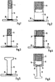
- Figur 1 eine Vorrichtung aus einem Bolzen mit einem aufgeschnittenen Gewindeteil und einer Ankerplatte,
- Figur 2 eine Vorrichtung aus einer Hülse mit einem Innengewinde und einer Ankerplatte,
- Figur 3 eine Vorrichtung aus einem Bolzen, einem aufgeschweißen Gewindeteil und einer Ankerplatte,
- Figur 4 eine Vorrichtung aus einer Gewindehülse, einem Rohrabschnitt und einer Ankerplatte,
- Figur 5 eine Vorrichtung aus einem Bolzen mit angestauchtem, vergrößertem Kopf und einer Ankerplatte,
- Figur 6 eine Vorrichtung aus einer topfartigen Hülse mit Sackbohrung und Innengewinde, sowie einem Bolzen mit angestauchtem, vergrößertem Kopf,
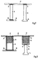
- Figur 7 eine Vorrichtung aus einer Befestigungsplatte mit zwei Bolzen,
- Figur 8 eine Vorrichtung aus einer Befestigungsplatte mit zwei Hülsen,
- Figur 9 eine Vorrichtung aus einer Kugel als Anschlußteil und einem pilzartig angestauchten und mit Außengewinde versehenen Bolzen als Verankerungsteil,
Figur 10 eine Vorrichtung aus einer Mutter mit vergrößerter Gewindelänge als Anschlußteil und einem angeschweißten Abschnitt einer Gewindestange als Verankerungsteil,Figur 11 eine Vorrichtung aus einer Gewindehülse als Anschlußteil und einer angeschweißten, pilzartigen Anstauchung als Verankerungsteil undFigur 12 eine als Doppelanker ausgebildete Vorrichtung, die aus zwei miteinander verschweißten Abschnitten einer Gewindestange als Verankerungsteile und zwei darauf aufgeschraubten Muttern als Anschlußteilen besteht.
- FIG. 1 shows a device consisting of a bolt with a cut-open threaded part and an anchor plate,
- FIG. 2 shows a device consisting of a sleeve with an internal thread and an anchor plate,
- FIG. 3 shows a device consisting of a bolt, a welded-on threaded part and an anchor plate,
- FIG. 4 shows a device consisting of a threaded sleeve, a tube section and an anchor plate,
- FIG. 5 shows a device consisting of a bolt with a compressed, enlarged head and an anchor plate,
- FIG. 6 shows a device consisting of a pot-like sleeve with a blind bore and an internal thread, and a bolt with a compressed, enlarged head,
- FIG. 7 shows a device consisting of a fastening plate with two bolts,
- FIG. 8 shows a device made from a mounting plate with two sleeves,
- FIG. 9 shows a device consisting of a ball as the connecting part and a mushroom-like bolt and an externally threaded bolt as the anchoring part,
- FIG. 10 shows a device consisting of a nut with an enlarged thread length as a connecting part and a welded-on section of a threaded rod as an anchoring part,
- Figure 11 shows a device from a threaded sleeve as a connecting part and a welded, mushroom-like upsetting as anchoring part and
- Figure 12 is a device designed as a double anchor, which consists of two welded sections of a threaded rod as anchoring parts and two nuts screwed onto it as connecting parts.
Die Vorrichtung nach Figur 1 besteht aus einem Bolzen 10, der von einem Rundmaterial abgelängt worden ist. Ein Ende dieses Bolzens wird in bekannter Weise mit einem Gewindeteil 11 versehen. Das andere Ende des Bolzens 10 wird mittels Reibschweißung mit der Ankerplatte 20 fest und unlösbar verbunden, wie der Schweißbereich 30 andeutet. Dieser Bereich erstreckt sich nur über beschränkte Zonen, so daß bei dieser Erwärmung und Verschweißung keine Spannungsfelder im Material entstehen, die die Festigkeit der Vorrichtung beeinträchtigen könnten. Dies ist besonders wichtig, wenn kohlenstoffreicher Beton- oder Baustahl als Ausgangsmaterial verwendet wird. Wird die Vorrichtung als Verbindungsteil eingesetzt, bei dem das Gewindeteil 1 aus dem Betonteil vorsteht, dann kann der Bolzen 10 aus Edelstahl bestehen und mit einer billigen Ankerplatte 20 aus Beton- oder Baustahl verbunden werden. Diese Ankerplatte 20 in rechteckigem, quadratischem oder rundem Querschnitt ist ein einfaches und billig herstellbares Stanzteil. Das Gewindeteil 11 nimmt ,,n Abhebewerkzeug oder einen Gegenverbinder auf, die mit einem entsprechenden Gewindeloch versehen sind.The device according to FIG. 1 consists of a
Wie Figur 2 zeigt, kann das Anschlußteil für das Abhebewerkzeug oder den Verbinder auch als Hülse 12 ausgebildet sein, die mittels Reibschweißung einseitig mit der Ankerplatte 20 verschlossen ist. Das freie Ende ist mit einem Innengewinde 13 versehen, das sich zumindest 'über einen Teil der Länge der Hülse 12 erstreckt. Auch hier erstreckt sich der Schweißbereich 30 nur über beschränkte Zonen der Hülse 12 und der Ankerplatte 20.As FIG. 2 shows, the connecting part for the lifting tool or the connector can also be designed as a
Wie die Figuren 3 und 4 zeigen, kann bei den Vorrichtungen der Figuren 1 und 2 der Aufwand an Edelstahl dadurch noch beachtlich reduziert und die Vorrichtung entsprechend verbilligt werden, daß der Bolzen 10 als gewindeloser Abschnitt mittels eines durch Reibschweißung erzeugten Schweißbereiches 31 mit einem getrennten Gewindeteil 11 verbunden wird oder daß die Hülse 12 als Rohrabschnitt mit einem Abschnitt einer Gewindehülse mittels Reibschweißung verbunden wird.As FIGS. 3 and 4 show, the expenditure of stainless steel can be considerably reduced in the devices of FIGS. 1 and 2, and the device can be made cheaper accordingly, that the
Bei dem Ausführungsbeispiel nach Figur 5 ist das freie Ende des Bolzens 10 durch Anstauchen zu einem im Querschnitt vergrößerten Kopf geformt, der als Gelenkteil 14 für ein Gelenkgegenstück eines Abhebewerkzeuges dienen kann.In the embodiment according to FIG. 5, the free end of the
Die Hülse 12 bei der Vorrichtung nach Figur 6 ist aus einem vollen Abschnitt eines Rundmaterials hergestellt. Nach dem Einbringen der Sackbohrung 15 wird das Innengewinde 13 eingebracht. Am Boden 16 der Hülse 12 kann mittels Reibschweißung ein Bolzen 10 mit angestauchtem Kopf als Verankerungsteil angebracht werden, wie der Schweißbereich 30 zeigt Ist die Fläche des Bodens 16 der Hülse 12 ausreichend groß, dann können mittels Reibschweißung in gleicher Weise auch mehrere Bolzen angebracht werden. Diese Bolzen 10 können mit einer gemeinsamen Ankerplatte verbunden sein, wobei diese Verbindungen ebenfalls durch Reibschweißung hergestellt werden.The
Bei der Vorrichtung nach Figur 7 wird als Anschlußteil eine Befestigungsplatte 40 verwendet, auf deren Rückseite mehrere Bolzen 10 als Verankerungsteile angebracht sind. Die Bolzen 10 sind mittels Reibschweißung an der Befestigungsplatte 40 angebracht, wie die Schweißbereiche 31 zeigen. Die freien Enden der Bolzen 10 können mit einzelnen oder einer gemeinsamen Ankerplatte 20 verbunden sein, wie der Schweißbereich 30 zeigt. Die freien Enden der Bolzen 10 können auch nur angestaucht sein und vergrößerte Köpfe bilden. Auf der Oberseite der Befestigungsplatte 40 können Träger, Streben oder dgl. angeschweißt werden.In the device according to FIG. 7, a
Wie die Figur 8 zeigt, kann die Befestigungsplatte 40 auch Bohrungen 41 und 42 aufweisen. Im Bereich jeder Bohrung 41 und 42 ist auf der Rückseite der Befestigungsplatte 40 mittels Reibschweißung eine Hülse 12 angebracht, wie die Schweißbereiche 31 andeuten.As FIG. 8 shows, the
Die Hülse 12 kann teilweise mit einem Innengewinde 13 versehen sein, wie im linken Teil der Zeichnung gezeigt ist. In dieses Innengewinde 13 kann durch die Bohrung 41 der Befestigungsplatte 40 direkt ein Gewindeteil einer Schraube oder dgl. eingeschraubt werden. Die Hülse 12 ist durch die Ankerplatte 20 verschlossen, die ebenfalls durch Reibschweißung angebracht wird, wie der Schweißbereich 30 andeutet.The
Die Hülse 12 kann auch topfartig ausgebildet sein, wie im rechten Teil der Zeichnung gezeigt ist. In das Innengewinde 13 kann durch die Bohrung 42 der Befestigungsplatte 40 direkt ein Gewindeteil einer Schraube od. dgl. eingeschraubt werden.The
Am Boden 16 dieser Hülse 12 ist ein Bolzen 10 mit angestauchtem Kopf als Verankerungsteil 14 angebracht und zwar mittels Reibschweißung, wie mit dem Schweißbereich 30 angedeutet ist.At the bottom 16 of this
Anstelle des angestauchten Kopfes kann der Bolzen 10 auch mit einer Ankerplatte 20 abgeschlossen werden. Der Bolzen 10 und diese Ankerplatte 20 sind wieder mittels Reibschweißung miteinander verbunden. Am Boden 16 der Hülse 12 können auch mehrere Bolzen 10 mit einzelnen Ankerplatten oder einer gemeinsamen Ankerplatte angebracht sein.Instead of the upset head, the
Wie Figur 9 zeigt, kann eine Ankervorrichtung für ein Abhebewerkzeug mit Klauen auch aus einer Kugel 17 mit einem angeschweißten Bolzen 10 bestehen. Die Kugel 17 bringt eine ausgezeichnete Gelenkverbindung zwischen dem Abhebewerkzeug und der Ankervorrichtung. Die Kugel 17 ist mittels Reibschweißung mit dem Bolzen 10 verbunden, wie der Schweißbereich 30 andeutet. Der Bolzen 10 ist auf seiner Außenseite mit einem groben Gewinde 18 versehen, das die Verankerung dieses Verankerungsteiles im Betonteil verbessert. Demselben Zweck dient auch die pilzartige Anstauchung 19 am freien Ende des Bolzens 10, die z.B. auch durch Erwärmung mittels Reibung und anschließendem Stauchen angebracht werden kann.As FIG. 9 shows, an anchor device for a lifting tool with claws can also consist of a
Die in Figur 10 gezeigte Anker- und/oder Verbindungsvorrichtung verwendet als Verankerungsteil einen Abschnitt 22 einer Gewindestange, der mittels Reibschweißung mit einer Mutter 21 als Anschlußteil verbunden ist, wie der Schweißbereich 30 erkennen laßt. Diese Mutter 21 hat eine Gewindelänge, die mindestens dem 1,5-fachen Gewindedurchmesser entspricht, um ausreichende Tragkraft zu erreichen.The anchor and / or connecting device shown in FIG. 10 uses a
Bei dem Anker- und/oder Verbindungsteil nach Figur 11 wird eine Gewindehülse 12' als Anschlußteil mittels Reibschweißung (Schweißbereich 30) mit einer Hülse 12 verbunden. Dabei kann die Hülse 12 am freien Ende eine pilzartige Anstauchung 23 aufweisen. Die Hülse 12 wird z.B. in einem Arbeitsgang an beiden Enden durch Reibung erwärmt und dann über den Schweißbereich 30 mit der Gewindehülse 12' verbunden. Gleichzeitig kann das andere Ende der Hülse 12 angestaucht werden.In the anchor and / or connecting part according to FIG. 11, a threaded sleeve 12 'is connected to a
In Figur 12 ist eine als Doppelanker ausgebildete Anker- und/oder Verbindungsvorrichtung gezeigt. Die beiden Abschnitte 22 und 22' einer Gewindestange werden mittels Reibschweißung miteinander verbunden, wobei der Schweißbereich 30 eine Art Wassersperre bildet, Auf das so zusammengesetzte Verankerungsteil werden die beiden Muttern 21 und 21' als Anschlußteil aufgeschraubt. Wie die Schweißnähte 24 uns 24' zeigen, werden die Muttern 21 und 21' unverdrehbar auf den Abschnitten 22 und 22' festgelegt. Diese Festlegung kann auch durch an sich bekanntes; Verstemmen erfolgen.FIG. 12 shows an anchor and / or connecting device designed as a double anchor. The two
Bei allen Anker- und/oder Verbindungsvorrichtungen wird der Vorteil erreicht, daß nur das kleine Anschlußteil in Edelmetall ausgeführt oder mit veredelter Oberfläche versehen sein muß. Das größere Verankerungsteil kann aus billigem Bau- oder Betonstahl bestehen bzw. mit unveredelter Oberfläche versehen sein. Die Verbindung der Teile durch Reibschweißung ist schnell und billig herzustellen und bringt nicht die Nachteile bekannter Schweißverbindungen.With all anchor and / or connecting devices, the advantage is achieved that only the small connecting part must be made of precious metal or be provided with a refined surface. The larger anchoring part can consist of cheap structural or reinforcing steel or can be provided with an unfinished surface. The connection of the parts by friction welding is quick and cheap to produce and does not have the disadvantages of known welded connections.
Bei der in Figur 6 gezeigten Anker- und Verbindungsvorrichtung kann die Verankerung dadurch noch verbessert werden, daß die topfartige Hülse am geschlossenen Ende durch Reibung erwärmt und durch Anstauchen im Querschnitt vergrössert ist. Auf diese Weise ergibt sich ein vergrößerter Verankerungsflansch, an den dann der Bolzen mit dem angestauchten freien Ende mittels Reibschweißung angebracht wird.In the anchor and connection device shown in FIG. 6, the anchoring can be improved further in that the cup-like sleeve is heated by friction at the closed end and is enlarged in cross-section by upsetting. This results in an enlarged anchoring flange to which the bolt with the compressed free end is then attached by means of friction welding.
Bei der Ankervorrichtung nach Figur 5 kann das Gelenkteil 14 in verschiedener Form ausgestaltet werden. Dies wird allein durch die Form des Stauchwerkzeuges bestimmt. Dieses Gelenkteil 14 kann so z.B. als Kugel, als Kegelstumpf, als Pilz oder als Sechskantmutter od. dgl. ausgebildet werden.In the anchor device according to FIG. 5, the
Claims (13)
Applications Claiming Priority (2)
| Application Number | Priority Date | Filing Date | Title |
|---|---|---|---|
| DE2739879 | 1977-09-05 | ||
| DE19772739879 DE2739879A1 (en) | 1977-09-05 | 1977-09-05 | ANCHOR AND / OR CONNECTING DEVICE, IN PARTICULAR FOR CONCRETE PART OR THE DGL. |
Publications (3)
| Publication Number | Publication Date |
|---|---|
| EP0001095A2 EP0001095A2 (en) | 1979-03-21 |
| EP0001095A3 EP0001095A3 (en) | 1979-04-04 |
| EP0001095B1 true EP0001095B1 (en) | 1980-12-10 |
Family
ID=6018119
Family Applications (1)
| Application Number | Title | Priority Date | Filing Date |
|---|---|---|---|
| EP19780100797 Expired EP0001095B1 (en) | 1977-09-05 | 1978-08-31 | Anchoring and/or joining device for concrete elements or the like |
Country Status (2)
| Country | Link |
|---|---|
| EP (1) | EP0001095B1 (en) |
| DE (1) | DE2739879A1 (en) |
Families Citing this family (20)
| Publication number | Priority date | Publication date | Assignee | Title |
|---|---|---|---|---|
| EP0019922A1 (en) * | 1979-06-05 | 1980-12-10 | Heinz G. Riss | Transport anchor with enlarged foot and lifting head |
| DE3017840C2 (en) * | 1980-05-09 | 1984-05-17 | Kaiser-Omnia Bausysteme Gmbh & Co, 6000 Frankfurt | Permanent formwork for a concrete ceiling and anchors for this |
| DE3107506A1 (en) * | 1981-02-27 | 1982-09-16 | Kraftwerk Union AG, 4330 Mülheim | Anchoring element |
| DE3338762A1 (en) * | 1983-10-26 | 1985-05-09 | Winfried Dipl.-Ing. 6365 Rosbach Schnabel | Anchoring of steel construction parts by screw connections in concrete |
| EP0158944A3 (en) * | 1984-04-14 | 1987-04-22 | Deha Baubedarf GmbH & Co. KG | Transport anchor for slinging prefabricated reinforced concrete parts to lifting gears |
| DE3415207A1 (en) * | 1984-04-21 | 1985-11-07 | Siegfried 7135 Wiernsheim Fricker | SUPPORT SCREW FOR FACADE PANELS |
| DE3526940A1 (en) * | 1985-07-27 | 1987-02-12 | Siegfried Fricker | ANCHOR TO CONCRETE IN HEAVY LOADS |
| FR2633959B1 (en) * | 1988-07-11 | 1992-07-24 | Arteon Marcel | ANCHORING PIECE, PARTICULARLY FOR CONCRETE |
| DE8906810U1 (en) * | 1989-05-31 | 1989-07-27 | Deutsche Kahneisen Gesellschaft West Gmbh, 1000 Berlin, De | |
| JPH0375201U (en) * | 1989-11-27 | 1991-07-29 | ||
| FR2676080A1 (en) * | 1991-04-30 | 1992-11-06 | Arteon Marcel | Anchoring component, in particular for reinforced concrete panel |
| DE20306327U1 (en) * | 2003-04-14 | 2003-06-18 | Philipp Gmbh Geb | sleeve anchor |
| KR101283436B1 (en) * | 2011-12-19 | 2013-07-09 | 이재호 | Plates-welded anchor channel and manufacturing method of it |
| EP2685019B1 (en) * | 2012-07-13 | 2015-07-15 | Gerhard Krummel | Connection element between two concrete components |
| CN103437430B (en) * | 2013-07-18 | 2016-01-20 | 浙江中隧桥波形钢腹板有限公司 | Outer flat inside butt strap arc stud welding corrugated sheet steel syndeton and construction technology |
| CN103982506B (en) * | 2014-05-16 | 2016-06-08 | 深圳大学 | A kind of welding quality that is effectively improved is held concurrently the peg shear connector of ductile fracture feature |
| GB2535486B (en) * | 2015-02-17 | 2020-12-23 | William Haley Eng Ltd | Embedment plates |
| US10501939B2 (en) | 2017-12-22 | 2019-12-10 | Lance Nill | Anchor platform assembly |
| DE202018100768U1 (en) * | 2018-02-13 | 2018-04-03 | PreConTech International GmbH | Anchorage for precast concrete elements |
| BR112021003957A2 (en) * | 2018-09-04 | 2021-05-25 | Lance Nill | Combined anchor and fixture mount for anchoring an object to a concrete structure, anchor deck mount system for anchoring an object to a structure, anchor deck mount, and method for anchoring an object to a concrete structure |
Family Cites Families (5)
| Publication number | Priority date | Publication date | Assignee | Title |
|---|---|---|---|---|
| CH260503A (en) * | 1948-06-14 | 1949-03-31 | Wehinger Franz | Sleeve dowel for walling in. |
| US2829514A (en) * | 1955-12-13 | 1958-04-08 | Eldon R Maclean | Hollow masonry block-attaching device |
| US3216157A (en) * | 1961-06-28 | 1965-11-09 | George S Pinter | Concrete structure and process for making same |
| DE1801457C3 (en) * | 1968-10-05 | 1974-06-27 | Juergen 7800 Freiburg Goldberg | Device for lifting and transporting precast concrete parts or the like |
| US3878659A (en) * | 1972-07-08 | 1975-04-22 | Hermann Pfeifer | Fitting for pre-cast concrete bodies |
-
1977
- 1977-09-05 DE DE19772739879 patent/DE2739879A1/en not_active Withdrawn
-
1978
- 1978-08-31 EP EP19780100797 patent/EP0001095B1/en not_active Expired
Also Published As
| Publication number | Publication date |
|---|---|
| EP0001095A3 (en) | 1979-04-04 |
| EP0001095A2 (en) | 1979-03-21 |
| DE2739879A1 (en) | 1979-03-15 |
Similar Documents
| Publication | Publication Date | Title |
|---|---|---|
| EP0001095B1 (en) | Anchoring and/or joining device for concrete elements or the like | |
| EP0758039B1 (en) | Anchorage rail for use in construction work | |
| DE2521426A1 (en) | BREAKING DEVICE FOR HOLDING A POST | |
| DE19913695A1 (en) | Tool for press device for rivet-type connection of components, e.g. as plates, bolts, nuts etc. with plate | |
| DE4410475A1 (en) | Rivetable element, assembly part with a rivetable element as well as rivet die and method for producing the assembly part | |
| DE10119505A1 (en) | Functional part has main body with annular flange leading into cylindrical rivet part and in-between conical surface, sheet metal part and locking part | |
| DE102009039817A1 (en) | Self-piercing nut member and assembly part consisting of the nut member and a sheet metal part | |
| WO2011161091A1 (en) | Connecting element for a friction-welded connection for connecting at least two panel-like components | |
| DE1285258B (en) | Connection between a metal plate and a nut and method of making the connection | |
| DE7200898U (en) | TINES FOR A POWER HARROW | |
| DE102005006615A1 (en) | Piercing nut | |
| DE2607154A1 (en) | Flange connection for chassis - has cup shaped grooves around fixing hole in profiled sections of holding flange | |
| DE2626808A1 (en) | DEVICE FOR FASTENING A PLATE PART TO A BASE PART | |
| DE3138329A1 (en) | "FASTENING ARRANGEMENT" | |
| EP0998613B1 (en) | Dowel pin for web reinforcements | |
| DE2605818A1 (en) | BOLT SCREW FOR FASTENING COMPONENTS TO HOLLOW BODIES | |
| DE102008023044B4 (en) | Method for attaching a joining or functional element to a plastically deformable flat material | |
| EP1379790B1 (en) | Method for producing a structural member comprising a metal sheet and a set screw and structural member. | |
| DE1064761B (en) | Dowel pin with grooved shaft | |
| DE102005059988B3 (en) | Weld-on nut, has weldable main body made of aluminum with square nut made of stainless steel pressed into its central recess and is also equipped with aluminum outer cover | |
| DE10111015B4 (en) | Vehicle chassis made of interconnected metal sheets | |
| DE3611245A1 (en) | Sheet-metal connection having a connecting element with shaft and head | |
| DE3039937A1 (en) | Carrier jaw braced on arched mine gallery support - has reinforcing ribs on hook heads of screws with bent hook shafts | |
| CH692555A5 (en) | A process for the manufacture of a reinforcing bar. | |
| DE2348074C2 (en) | "Train connection between a sheet pile wall and a tie rod formed by a rolled section with a connecting part" |
Legal Events
| Date | Code | Title | Description |
|---|---|---|---|
| PUAI | Public reference made under article 153(3) epc to a published international application that has entered the european phase |
Free format text: ORIGINAL CODE: 0009012 |
|
| PUAL | Search report despatched |
Free format text: ORIGINAL CODE: 0009013 |
|
| AK | Designated contracting states |
Designated state(s): BE CH FR GB LU NL SE |
|
| AK | Designated contracting states |
Designated state(s): BE CH FR GB LU NL SE |
|
| 17P | Request for examination filed | ||
| GRAA | (expected) grant |
Free format text: ORIGINAL CODE: 0009210 |
|
| AK | Designated contracting states |
Designated state(s): BE CH FR GB LU NL SE |
|
| PGFP | Annual fee paid to national office [announced via postgrant information from national office to epo] |
Ref country code: LU Payment date: 19810508 Year of fee payment: 4 |
|
| PGFP | Annual fee paid to national office [announced via postgrant information from national office to epo] |
Ref country code: FR Payment date: 19810707 Year of fee payment: 4 |
|
| PGFP | Annual fee paid to national office [announced via postgrant information from national office to epo] |
Ref country code: SE Payment date: 19810731 Year of fee payment: 4 |
|
| PG25 | Lapsed in a contracting state [announced via postgrant information from national office to epo] |
Ref country code: LU Free format text: LAPSE BECAUSE OF NON-PAYMENT OF DUE FEES Effective date: 19810831 |
|
| PGFP | Annual fee paid to national office [announced via postgrant information from national office to epo] |
Ref country code: NL Payment date: 19810831 Year of fee payment: 4 |
|
| PGFP | Annual fee paid to national office [announced via postgrant information from national office to epo] |
Ref country code: CH Payment date: 19810930 Year of fee payment: 4 Ref country code: BE Payment date: 19810930 Year of fee payment: 4 |
|
| PG25 | Lapsed in a contracting state [announced via postgrant information from national office to epo] |
Ref country code: CH Effective date: 19820831 |
|
| PG25 | Lapsed in a contracting state [announced via postgrant information from national office to epo] |
Ref country code: SE Effective date: 19820901 |
|
| PG25 | Lapsed in a contracting state [announced via postgrant information from national office to epo] |
Ref country code: NL Effective date: 19830301 |
|
| NLV4 | Nl: lapsed or anulled due to non-payment of the annual fee | ||
| PG25 | Lapsed in a contracting state [announced via postgrant information from national office to epo] |
Ref country code: FR Free format text: LAPSE BECAUSE OF NON-PAYMENT OF DUE FEES Effective date: 19830429 |
|
| REG | Reference to a national code |
Ref country code: CH Ref legal event code: PL |
|
| REG | Reference to a national code |
Ref country code: FR Ref legal event code: ST |
|
| PG25 | Lapsed in a contracting state [announced via postgrant information from national office to epo] |
Ref country code: BE Effective date: 19830831 |
|
| GBPC | Gb: european patent ceased through non-payment of renewal fee | ||
| PG25 | Lapsed in a contracting state [announced via postgrant information from national office to epo] |
Ref country code: GB Effective date: 19881117 |
|
| EUG | Se: european patent has lapsed |
Ref document number: 78100797.6 Effective date: 19850611 |
|
| PLBE | No opposition filed within time limit |
Free format text: ORIGINAL CODE: 0009261 |
|
| STAA | Information on the status of an ep patent application or granted ep patent |
Free format text: STATUS: NO OPPOSITION FILED WITHIN TIME LIMIT |