EP0000735B1 - Dispositif de commande réglable pour moteur d'un fauteuil pour soins dentaires - Google Patents
Dispositif de commande réglable pour moteur d'un fauteuil pour soins dentaires Download PDFInfo
- Publication number
- EP0000735B1 EP0000735B1 EP78100514A EP78100514A EP0000735B1 EP 0000735 B1 EP0000735 B1 EP 0000735B1 EP 78100514 A EP78100514 A EP 78100514A EP 78100514 A EP78100514 A EP 78100514A EP 0000735 B1 EP0000735 B1 EP 0000735B1
- Authority
- EP
- European Patent Office
- Prior art keywords
- adjusted
- drive motor
- counter
- control device
- motor
- Prior art date
- Legal status (The legal status is an assumption and is not a legal conclusion. Google has not performed a legal analysis and makes no representation as to the accuracy of the status listed.)
- Expired
Links
- 230000015654 memory Effects 0.000 description 10
- 230000005540 biological transmission Effects 0.000 description 2
- 230000007257 malfunction Effects 0.000 description 2
- 230000004913 activation Effects 0.000 description 1
- 238000006243 chemical reaction Methods 0.000 description 1
- 230000008094 contradictory effect Effects 0.000 description 1
- 230000001419 dependent effect Effects 0.000 description 1
- 238000011161 development Methods 0.000 description 1
- 230000018109 developmental process Effects 0.000 description 1
- 238000010586 diagram Methods 0.000 description 1
- 238000000034 method Methods 0.000 description 1
Images
Classifications
-
- A—HUMAN NECESSITIES
- A61—MEDICAL OR VETERINARY SCIENCE; HYGIENE
- A61G—TRANSPORT, PERSONAL CONVEYANCES, OR ACCOMMODATION SPECIALLY ADAPTED FOR PATIENTS OR DISABLED PERSONS; OPERATING TABLES OR CHAIRS; CHAIRS FOR DENTISTRY; FUNERAL DEVICES
- A61G15/00—Operating chairs; Dental chairs; Accessories specially adapted therefor, e.g. work stands
- A61G15/02—Chairs with means to adjust position of patient; Controls therefor
-
- G—PHYSICS
- G05—CONTROLLING; REGULATING
- G05B—CONTROL OR REGULATING SYSTEMS IN GENERAL; FUNCTIONAL ELEMENTS OF SUCH SYSTEMS; MONITORING OR TESTING ARRANGEMENTS FOR SUCH SYSTEMS OR ELEMENTS
- G05B19/00—Programme-control systems
- G05B19/02—Programme-control systems electric
- G05B19/18—Numerical control [NC], i.e. automatically operating machines, in particular machine tools, e.g. in a manufacturing environment, so as to execute positioning, movement or co-ordinated operations by means of programme data in numerical form
- G05B19/19—Numerical control [NC], i.e. automatically operating machines, in particular machine tools, e.g. in a manufacturing environment, so as to execute positioning, movement or co-ordinated operations by means of programme data in numerical form characterised by positioning or contouring control systems, e.g. to control position from one programmed point to another or to control movement along a programmed continuous path
- G05B19/40—Open loop systems, e.g. using stepping motor
Definitions
- the invention relates to a device for controlling the seat or the backrest of a dental treatment chair, which can be adjusted in several positions by motor, using actual value transmitters and setpoint transmitters designed as electronic read-only memories for forming electrical signals that correspond to the actual or desired value of the embody the adjusting object and a comparator that compares the setpoint with the actual value of the object to be adjusted and, in the presence of a difference depending on the sign of the difference, provides the drive motor with a signal for switching on the motor in one or the other direction of rotation, whereby for the object to be adjusted there are several setpoint transmitters embodying the adjustable positions.
- electromechanical transmitters in the form of potentiometers are provided as setpoint and actual value transmitters (DE-A-19 23 262 and DE-A-22 51 737).
- setpoint and actual value transmitters DE-A-19 23 262 and DE-A-22 51 737.
- the setting and adjustment of the potentiometers and the programming of the setpoint device is relatively complex.
- the electromechanical feedback devices also tend to malfunction.
- the setpoints are specified in part by electromechanical setpoints in the form of potentiometers, in part also by electronic setpoint voltage transmitters;
- the electronic setpoint voltage transmitters contain digital counters, to the output of which a resistor network with a large number of individual resistors is connected. When the counter runs, a step-like rise occurs at the output of the resistance network.
- the resulting output signals are fed as analog signals (voltage) to an analog comparator and compared in a conventional manner with analog values from a potentiometer forming the actual value.
- the analog signal from the electromechanical setpoint generator can be entered directly into the analog comparator.
- Such a control device is relatively complex in terms of circuitry, in particular because of the conversion of the digital signals obtained from the counters of the electronic setpoint transmitters into analog signals.
- the existing electromechanical encoders in the form of the potentiometers as actual value transmitters (and partly as setpoint transmitters) are also not sufficiently immune to interference.
- the setting and adjustment of the actual value potentiometers in dental treatment chairs is particularly difficult and can only be carried out by the service technician.
- the positions of the objects to be adjusted are determined by punch cards, which are entered into a transmission device if necessary. Apart from the fact that the handling of such punch cards is relatively cumbersome because the desired card has to be fetched from an archive, such cards are subject to wear and tear.
- the transmission device for scanning the respective punch card also represents an interference factor.
- the invention has for its object to provide a control device of the type mentioned, in which no punch cards or the like. are required, which contains no parts which are difficult to adjust and prone to malfunction, and which is simpler and more reliable in terms of circuitry than known control devices of this type.
- the object is achieved according to the invention in that the actual value of the object to be adjusted is formed by a clock generator coupled to the associated drive motor, which emits pulses which are picked up by a counter, counted and added or subtracted depending on the direction of rotation of the drive motor, and that a pulse counter comparator is provided, which is connected on the one hand to the output of the counter and on the other hand to the read-only memory and compares the counter reading of the counter with that of the read-only memory, such that the drive motor via a switching amplifier in the presence of a difference depending on the sign of the Difference in one or the other direction of rotation is switched on and switched off at the same counter reading.
- control device Accordingly advantages of the control device according to the invention can be seen in the relatively low complexity in terms of circuitry and in the direct, purely digital control and in the direct comparison of the target and actual values via a counter reading comparator.
- position counters and fixed value transmitters are known in the field of machine tool control for positioning an adjustable machine part, for example the tool slide, relative to a fixed machine stand (DE-A-24 18 909).
- the known device serves to improve the positioning of the machine part in such a way that counting fields are prevented from being carried over in the case of multiple positioning, and the positioning accuracy is thus increased without synchronization via the starting position.
- the position counter is switched on by a number of counting pulses, which is dependent on the adjustment, of a pulse generator controlled by the adjusting device of the machine part. In this way, a synchronization of the position counter is achieved at fixed predetermined adjustment positions.
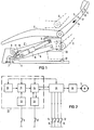
- Fig. 1 shows a schematic representation of a dental chair seen from the side.
- the chair consists essentially of a base part 1 to which a parallelogram support arm 2 is articulated, the free end of which is mounted in a support 3 for a seat 4 and a backrest 5.
- Seat 4 and backrest 5 together form the upper part of the chair, which can be adjusted in height by means of the parallelogram support arm 2 in the two positions and II indicated by dashed lines.
- An electric motor-driven spindle drive 6 with a spindle arranged diagonally between two articulation points of the parallelogram arm 2 is provided as the adjusting device.
- the associated drive motor 7 is arranged outside the parallelogram support arm 2 in a housing of the base part 1. The torque of the motor 7 is transmitted to the spindle via V-belts (not shown) and an intermediate shaft.
- the parallelogram support arm 2 contains two link arms 8 and 10.
- a switch 9 is fastened to the lower link arm 8 and is switched by means of a switching lug 11 arranged on the upper link arm 10 at a specific angular position of the parallelogram arm and thus a specific height position of the seat 4. As will be explained again later, the switch 9 is used to trigger a correction process.
- an emergency stop switch arranged on the base part 1 is designated, which is switched either when actuated by the foot of an operator or when the carrier 3 is placed on it.
- FIG. 13 denotes a program control, which is explained in more detail in FIG. 2 and which contains the electronic components required for storage and retrieval.
- the switch 14 with a toggle switch is designated, with which the drive motor 7 can be switched on in one or the other direction of rotation depending on the toggle position of the switch and thus an upward or downward movement of the seat can be initiated.
- the switch 14 has a defined rest position in both switching directions, i.e. after releasing the actuator, the switch always returns to its rest position. In this position, the circuit of the drive motor is then interrupted.
- 15 and 16 denote program switches with which two different, fixed positions for the seat height can be called up. A program is entered via switch 17.
- the actual value of the object to be adjusted (here the seat 4) is formed from the switch-on time and the direction of rotation of the drive motor 7.
- the switch-on time is obtained from the mains voltage applied to the switched-on motor 7.
- a clock 20 gives pulses according to the mains frequency of the motor to a counter 21 which, depending on whether the motor is running in one or the other direction of rotation and thus the seat is raised or lowered, adds or subtracts the pulses obtained. If, for example, the motor is switched on in the direction of rotation that causes the seat to be raised, the grid periods are added; conversely, when the chair is lowered, the network periods are subtracted.
- a correction element 22 which corrects the counter reading of the counter element 21 when the correction switch 9 is switched on .
- the switch 9 is, as shown in Fig. 1, between the lowest and the uppermost position of the chair fixed to the object to be adjusted. When a certain point is passed, it is closed. As a result, the correction element 22 receives a switching pulse, which causes the count of the counter element 21 to be compared with that of the correction element 22. If the counter reading deviates, the counter member 21 is brought to the counter reading of the correction member 22.
- an electronic permanent memory 23 e.g. an EA-PROM memory is used.
- 24 denotes a comparator which compares the actual values from the counter 21 with the target values of the memory 23.
- coincidence element 25 is a logic logic circuit (coincidence element) which, when the switch 14 or one of the switches 15 or 16, with which the stored programs can be called up, checks whether this switching or control command is correct. Are there, for example, contradicting commands for this working group? for example, by switching on the two switches 15 and 16, that is to say the simultaneous activation of two different programs, then the coincidence element 25 refuses to pass on a command. If, on the other hand, the control command is clear, it is passed on to the drive motor 7 via a switching amplifier 26. At the same time, the clock generator 20 and the counter 21 are asked to form the actual value. The counter 21 thus runs as long as the motor 7 is switched on.
- the comparator 24 first checks whether there is a difference between the count of the counter 21 and the count of the memory 23. If there is one, depending on the sign of the difference, the switching amplifier 26 switches on the motor in the required direction of rotation. If the counter reading, that is to say the actual and target values, matches, the comparator 24 triggers the shutdown of the motor 7. The engine 7 is also switched off when the emergency stop button 12 is actuated.
- the chair To save a program, the chair must first be moved to the desired position by hand. This is done by actuating the hand switch 14. By actuating the program input key 17, the program memory 23 is now prepared via the comparator 24 for accepting the position values. If one of the program keys 15 or 16 to which the desired program is to be assigned is then pressed, the memory element 23 takes the present actual value from the counter element 21. In the same way, the other program, which is called up via the switch 16, can be stored.
Landscapes
- Engineering & Computer Science (AREA)
- Human Computer Interaction (AREA)
- Manufacturing & Machinery (AREA)
- Physics & Mathematics (AREA)
- General Physics & Mathematics (AREA)
- Automation & Control Theory (AREA)
- Health & Medical Sciences (AREA)
- Life Sciences & Earth Sciences (AREA)
- Animal Behavior & Ethology (AREA)
- General Health & Medical Sciences (AREA)
- Public Health (AREA)
- Veterinary Medicine (AREA)
- Accommodation For Nursing Or Treatment Tables (AREA)
- Dental Tools And Instruments Or Auxiliary Dental Instruments (AREA)
Claims (6)
Applications Claiming Priority (2)
| Application Number | Priority Date | Filing Date | Title |
|---|---|---|---|
| DE2736276A DE2736276B1 (de) | 1977-08-11 | 1977-08-11 | Steuereinrichtung fuer ein zahnaerztliches Geraet |
| DE2736276 | 1977-08-11 |
Publications (2)
| Publication Number | Publication Date |
|---|---|
| EP0000735A1 EP0000735A1 (fr) | 1979-02-21 |
| EP0000735B1 true EP0000735B1 (fr) | 1981-03-18 |
Family
ID=6016178
Family Applications (1)
| Application Number | Title | Priority Date | Filing Date |
|---|---|---|---|
| EP78100514A Expired EP0000735B1 (fr) | 1977-08-11 | 1978-07-26 | Dispositif de commande réglable pour moteur d'un fauteuil pour soins dentaires |
Country Status (4)
| Country | Link |
|---|---|
| US (1) | US4250439A (fr) |
| EP (1) | EP0000735B1 (fr) |
| DE (2) | DE2736276B1 (fr) |
| IT (1) | IT1097677B (fr) |
Families Citing this family (16)
| Publication number | Priority date | Publication date | Assignee | Title |
|---|---|---|---|---|
| DE2746630A1 (de) * | 1977-10-17 | 1979-04-26 | Koepp Elektronik Gmbh | Elektrische steuerschaltung zur lageeinstellung eines aerztlichen behandlungsstuhles oder dergleichen |
| DE2912755C2 (de) * | 1979-03-30 | 1984-08-09 | Kaltenbach & Voigt Gmbh & Co, 7950 Biberach | Schaltungsanordnung zur Steuerung der Bewegung eines Arbeitsgerätes, insbesondere eines zahnärztlichen Behandlungsstuhles |
| JPS607805B2 (ja) * | 1979-08-01 | 1985-02-27 | 株式会社 モリタ製作所 | 被制御物の位置の記憶及び読み出し再現制御装置 |
| DE3015070C2 (de) * | 1980-04-18 | 1986-07-10 | Siemens AG, 1000 Berlin und 8000 München | Steuereinrichtung für einen zahnärztlichen Behandlungsstuhl |
| US4463300A (en) * | 1981-09-17 | 1984-07-31 | Printronix, Inc. | Linear motor digital servo control |
| JPS58105834A (ja) * | 1981-12-17 | 1983-06-23 | Nissan Motor Co Ltd | シ−ト位置自動選定装置 |
| CH670164A5 (fr) * | 1986-07-22 | 1989-05-12 | Landis & Gyr Ag | |
| US5214360A (en) * | 1992-03-13 | 1993-05-25 | Den-Tal-Ez, Inc. | Programmable adjustable chair for medical and dental applications |
| USD347946S (en) | 1993-06-10 | 1994-06-21 | A-Dec, Inc. | Dental chair |
| EP0862348A1 (fr) | 1997-02-28 | 1998-09-02 | Alcatel | Dispositif d'interface pour l'extraction d'ensembles M de bits à partir d'ensembles N de bits, unité de contrÔle et cellule logique |
| FR2816184B1 (fr) * | 2000-11-08 | 2003-02-21 | Labinal | Dispositif d'actionnement d'un element de siege et siege le comportant |
| JP4338494B2 (ja) * | 2003-10-14 | 2009-10-07 | パラマウントベッド株式会社 | 電動ベッドの動作制御装置 |
| DE102008002805A1 (de) * | 2008-03-14 | 2009-10-01 | Aquatec Operations Gmbh | Dusch- und Toilettenstuhl |
| CN107568985B (zh) * | 2012-02-28 | 2020-03-06 | 德沃特奥金有限公司 | 用于家具的电动家具驱动器、用于监控电动家具驱动器的脉宽比的方法及相应的家具 |
| WO2015172791A2 (fr) * | 2014-05-11 | 2015-11-19 | Saber Iman Mohamed Said | Mise à niveau de l'unité dentaire |
| US10632037B2 (en) * | 2018-02-01 | 2020-04-28 | Medical Technology Industries, Inc. | Programmable examination and procedure tables and chairs |
Family Cites Families (9)
| Publication number | Priority date | Publication date | Assignee | Title |
|---|---|---|---|---|
| US3370289A (en) * | 1965-02-26 | 1968-02-20 | Collins Radio Co | Digital-to-analog converter system |
| US3465217A (en) * | 1965-02-26 | 1969-09-02 | Collins Radio Co | Digitalized shaft rotation direction control |
| US3984146A (en) * | 1970-03-31 | 1976-10-05 | Siemens Aktiengesellschaft | Apparatus for actuating operational chairs |
| US3675107A (en) * | 1970-10-01 | 1972-07-04 | Houdaille Industries Inc | Turret indexing control system |
| DE2251737B2 (de) * | 1972-10-21 | 1978-04-13 | Siemens Ag, 1000 Berlin Und 8000 Muenchen | Zahnarztlicher Patientenstuhl mit Parallelogrammtragarm |
| DE2412550C2 (de) * | 1974-03-15 | 1980-11-27 | Siemens Ag, 1000 Berlin Und 8000 Muenchen | Programmsteuereinrichtung für einen zahnärztlichen Operationsstuhl |
| DE2418909A1 (de) * | 1974-04-19 | 1975-11-06 | Karl Friedrich Dipl Ing Heine | Vorrichtung zur positionierung eines verstellbaren maschinenteiles, vorzugsweise bei einer werkzeugmaschine |
| DE2554059C3 (de) * | 1975-12-02 | 1978-09-21 | Koepp Elektronik Gmbh, 6057 Dietzenbach | Steuerschaltung zur Lageeinstellung eines ärztlichen Behandlungsstuhles o.dgl |
| JPS52151291A (en) * | 1976-06-11 | 1977-12-15 | Taiko Iryoki Seisakusho Kk | Chair for netal treatment |
-
1977
- 1977-08-11 DE DE2736276A patent/DE2736276B1/de not_active Withdrawn
-
1978
- 1978-07-26 EP EP78100514A patent/EP0000735B1/fr not_active Expired
- 1978-07-26 DE DE7878100514T patent/DE2860544D1/de not_active Expired
- 1978-07-31 US US05/929,344 patent/US4250439A/en not_active Expired - Lifetime
- 1978-08-04 IT IT26488/78A patent/IT1097677B/it active
Also Published As
| Publication number | Publication date |
|---|---|
| EP0000735A1 (fr) | 1979-02-21 |
| DE2736276B1 (de) | 1978-11-09 |
| DE2860544D1 (en) | 1981-04-16 |
| IT1097677B (it) | 1985-08-31 |
| IT7826488A0 (it) | 1978-08-04 |
| US4250439A (en) | 1981-02-10 |
Similar Documents
| Publication | Publication Date | Title |
|---|---|---|
| EP0000735B1 (fr) | Dispositif de commande réglable pour moteur d'un fauteuil pour soins dentaires | |
| DE2660912C2 (de) | Programmsteuerung für einen Manipulator | |
| DE69210924T2 (de) | Einrichtung zum Drehen einer Überwachungskamera | |
| DE2726100B2 (de) | Zahnärztlicher Behandlungsstuhl | |
| DE2148237A1 (de) | Einstellvorrichtung für die Druckfarbenversorgung | |
| DE3207068C2 (de) | Schaltungsanordnung zur Steuerung der Bewegung einer Einstellvorrichtung, insbesondere eines Patientenstuhles | |
| DE2710049C2 (de) | Ultraschall-Zahnbehandlungsgerät | |
| CH625090A5 (fr) | ||
| DE3726885C2 (de) | Stellgerät | |
| DE3133246C2 (de) | Elektrische Steuerungsvorrichtung für die anschlaglose Wegbegrenzung an Werkzeugmaschinen, insbesondere an Honmaschinen | |
| DE2824510A1 (de) | Vorrichtung zum steuern der torbewegung von elektrisch betriebenen toren | |
| DE2313569A1 (de) | Schleifmaschine | |
| DE2340636C3 (de) | Einrichtung zum schrittweisen Ausziehen eines Stranges aus einer horizontalen Stranggießkokille | |
| DE2412550C2 (de) | Programmsteuereinrichtung für einen zahnärztlichen Operationsstuhl | |
| EP0038451B1 (fr) | Dispositif de contrôle pour une chaise dentaire | |
| EP0678271B1 (fr) | Circuit pour régler la puissance d'aspiration d'un aspirateur de poussière | |
| DE3010147C2 (fr) | ||
| DE2531858A1 (de) | Digitalarbeitende schaltungsanordnung zur automatischen belichtungssteuerung fuer photographische kameras | |
| DE2340385C2 (de) | Einrichtung zur Axialverstellung des Nadelzylinders in einer Rundstrickmaschine | |
| DE3844149A1 (de) | Walzenzufuehrungseinrichtung | |
| EP0464376B1 (fr) | Levier d'un interrupteur avec un dispositif pour l'ajustage du point de contact d'un commutateur électrique pour minuteries électromécaniques | |
| DE3824547C2 (de) | Verfahren zur Steuerung eines auf Handbetrieb umschaltbaren motorischen Antriebs, Motorsteuerung mit Umschaltung auf Handbetrieb und deren Verwendung | |
| DE2412550C3 (fr) | ||
| DE2942323C2 (de) | Anordnung zur Fütterung von Tieren mit Naßfutter | |
| DE2129128C3 (de) | Schaltung zum Steuern eines Taktgenerators mit veränderbarer Taktfrequenz, dessen Ausgang an den Eingang eines digitalen Zählers angeschlossen ist |
Legal Events
| Date | Code | Title | Description |
|---|---|---|---|
| PUAI | Public reference made under article 153(3) epc to a published international application that has entered the european phase |
Free format text: ORIGINAL CODE: 0009012 |
|
| AK | Designated contracting states |
Designated state(s): DE FR GB SE |
|
| 17P | Request for examination filed | ||
| GRAA | (expected) grant |
Free format text: ORIGINAL CODE: 0009210 |
|
| AK | Designated contracting states |
Designated state(s): DE FR GB SE |
|
| REF | Corresponds to: |
Ref document number: 2860544 Country of ref document: DE Date of ref document: 19810416 |
|
| PGFP | Annual fee paid to national office [announced via postgrant information from national office to epo] |
Ref country code: SE Payment date: 19840630 Year of fee payment: 7 |
|
| PG25 | Lapsed in a contracting state [announced via postgrant information from national office to epo] |
Ref country code: GB Effective date: 19880726 |
|
| PG25 | Lapsed in a contracting state [announced via postgrant information from national office to epo] |
Ref country code: SE Effective date: 19880727 |
|
| GBPC | Gb: european patent ceased through non-payment of renewal fee | ||
| PGFP | Annual fee paid to national office [announced via postgrant information from national office to epo] |
Ref country code: FR Payment date: 19910718 Year of fee payment: 14 |
|
| PGFP | Annual fee paid to national office [announced via postgrant information from national office to epo] |
Ref country code: DE Payment date: 19910917 Year of fee payment: 14 |
|
| PG25 | Lapsed in a contracting state [announced via postgrant information from national office to epo] |
Ref country code: FR Effective date: 19930331 |
|
| PG25 | Lapsed in a contracting state [announced via postgrant information from national office to epo] |
Ref country code: DE Effective date: 19930401 |
|
| REG | Reference to a national code |
Ref country code: FR Ref legal event code: ST |
|
| EUG | Se: european patent has lapsed |
Ref document number: 78100514.5 Effective date: 19890510 |
|
| PLBE | No opposition filed within time limit |
Free format text: ORIGINAL CODE: 0009261 |
|
| STAA | Information on the status of an ep patent application or granted ep patent |
Free format text: STATUS: NO OPPOSITION FILED WITHIN TIME LIMIT |