EP0000011B2 - Bogenrotationsdruckmaschine. - Google Patents
Bogenrotationsdruckmaschine. Download PDFInfo
- Publication number
- EP0000011B2 EP0000011B2 EP78100018A EP78100018A EP0000011B2 EP 0000011 B2 EP0000011 B2 EP 0000011B2 EP 78100018 A EP78100018 A EP 78100018A EP 78100018 A EP78100018 A EP 78100018A EP 0000011 B2 EP0000011 B2 EP 0000011B2
- Authority
- EP
- European Patent Office
- Prior art keywords
- sheet
- drum
- guide plate
- sheet transfer
- printing
- Prior art date
- Legal status (The legal status is an assumption and is not a legal conclusion. Google has not performed a legal analysis and makes no representation as to the accuracy of the status listed.)
- Expired
Links
- 238000011144 upstream manufacturing Methods 0.000 description 3
- 238000013459 approach Methods 0.000 description 1
- 230000015572 biosynthetic process Effects 0.000 description 1
- 230000000694 effects Effects 0.000 description 1
- 238000005461 lubrication Methods 0.000 description 1
- 230000037303 wrinkles Effects 0.000 description 1
Images
Classifications
-
- B—PERFORMING OPERATIONS; TRANSPORTING
- B41—PRINTING; LINING MACHINES; TYPEWRITERS; STAMPS
- B41F—PRINTING MACHINES OR PRESSES
- B41F21/00—Devices for conveying sheets through printing apparatus or machines
- B41F21/10—Combinations of transfer drums and grippers
- B41F21/106—Combinations of transfer drums and grippers for reversing sheets, e.g. for perfecting machine
Definitions
- the invention relates to a sheet-fed rotary printing press for face and back printing with sheet transfer drums arranged between the printing units, under which stationary sheet-guiding plates extending over their entire width are provided.
- a device for sheet transfer and application in which hollow sheet guide bars with air outlet openings are arranged below the transfer point of the sheet between the printing cylinder and sheet transfer drum. Air is blown out of these air outlet openings with increased pressure in order to prevent the fine pressure on the sheet guiding bars from being smeared off.
- the DT-PS 21 28 216 discloses a device for sheet transfer and use in printing presses for optional face or reverse printing, in which a sheet transfer drum together with the upstream printing cylinder represent a sheet turning station. Both under the impression cylinder and under the sheet transfer drum, a sheet guide plate is provided stationary at a short distance from the drum or cylinder circumference, which are connected to one another via an adjustable third or middle sheet guide plate. The last-mentioned sheet guide plate can be converted into a face and a face and back printing position.
- all three sheet guide plates form a closed guide which, tangentially starting from the circumference of the impression cylinder, opens into an equidistant path running near the circumference of the sheet transfer drum.
- the middle sheet is used as a paddock; a thrust loop is pivoted into the gap between the printing cylinder and the sheet transfer drum, so that it extends tangentially to it at a short distance from the circumference of the sheet transfer drum.
- a disadvantage of the known device is that in the perfecting position because of the tangential. Guiding the sheet guide in the reversal of the movement of the sheet guided by the impression cylinder, so when it has been detected at its rear edge, because of its low speed at this time and its movement parallel to the sheet guide, it tends very easily to at least with its rear end on the Lay the sheet guide plate, whereby the printed underside of the sheet is smeared. But the face-to-face position of the middle sheet guide plate is also not without problems. Experiments have shown that the sheet end tends to stick to the cylinder circumference of the impression cylinder or to overtake the cylinder in the case of particularly smooth papers, which is why it slides over the upper edge of the middle sheet sheet employed.
- the second turning station is now, for example, in a five-color press with two turning stations between printing unit two and three, the underside of the sheet is printed on a four-color fine and single-color counterprint. Despite the fine printing position of the sheet guide plate, this printed underside of the sheet smears because it is pulled over the edge of the adjusted sheet guide plate.
- the object of the invention is to attach sheet guide plates under sheet transfer drums in such a stationary manner that the sheet is gently guided both in straight printing and in perfecting and smearing of a printed underside of the sheet does not occur.
- the invention consists in that the sheet guide plate of the sheet transfer drum upstream of a printing cylinder approaches the drum circumference in the direction of drum rotation and the sheet guide plate of the sheet transfer drum which is respectively arranged downstream of the printing cylinder moves away from the drum circumference in the direction of drum rotation, such that there is between the underside of the sheet transported by the respective sheet transfer drum and the associated guide plate inevitably forms an air cushion at every machine speed, the sheet transfer drum arranged directly in front of the printing cylinder being designed as a turning drum and the end of the sheet transfer plate, which is arranged upstream of the turning drum, runs almost radially to the turning drum, that is to say downwards, from the turning drum points.
- DE-B-2544566 and DE-B-25 52 998 have already made known sheet guiding plates for chain chain laying, which are intended to feed the sheet taken from the last printing unit to the delivery stack without smearing by forming an air cushion.
- the lower end of the sheet guide plate is guided tangentially past the take-up drum in the form of an extension. This measure cannot prevent the ends of stiffer sheets from spreading from the take-off drum and hitting the edge of the sheet guide plate before an air cushion forms. Lubrication of the printed sheet side cannot consequently be prevented with a sheet guide plate extending tangentially beyond the removal drum.
- the second-mentioned also referring to a sheet delivery DE-B-2552998 shows a sheet guide plate, which begins directly in the vicinity of the sheet transfer point between the last printing cylinder and the chain delivery and steadily, z. B. spirally, removed from the take-off drum.
- this measure promotes the formation of an air cushion on the sheet guide plate, because the trailing edge of the sheet lies against the spiral-shaped sheet guide plate end and thereby pushes an air cushion in front of it.
- An air cushion is only formed in cooperation with the baffle section under the chain arm.
- both curved guide plate guides in the known chain brackets do not give any indication as to how a curved guide plate is to be formed under a turning drum, namely pointing radially downward, in order to reliably prevent smearing.
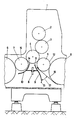
- a printing unit 1 of a multicolor printing machine which is located in the middle area, is shown, which can be converted from straight printing to face and back printing.
- the printing unit 1 consists, as usual, of a plate cylinder 2, a blanket cylinder 3 and a printing cylinder 4.
- the printing cylinder 4 is preceded by a sheet transfer drum 5 designed as a reversing drum and a sheet transfer drum 6 provided with a double diameter.
- a sheet transfer drum 7 with a diameter that corresponds to that of the printing cylinder 4.
- the sheet transfer drum 7 there is again a sheet transfer drum 6 with a double diameter.
- the sheet transfer drum5 is therefore only called turning drum in the following.
- Both sheet guide plates 10 and 10 are fastened to a crossbar 8 fixed to the housing and which extends below the printing cylinder 4. Both sheet guide plates 9 and 10 extend over the entire width of the sheet transfer drums.
- the sheet guide plate 9 is located under the turning drum 5 and the sheet guide plate 10 is located under the sheet transfer drum 7.
- the upper end 11 of the sheet guide plate 9 begins in the immediate vicinity of the printing cylinder 4, then runs parallel for a short distance at a short distance, i. H. Equidistant from the drum circumference 12 of the turning drum 5, it then moves away from the drum circumference 12 and practically opens into the lower end 13, which runs almost radially to the turning drum 5 and extends almost as far downward as the sheet transfer drum 6 with a double diameter .
- the sheet guide plate 9 has a slightly sinusoidally curved shape.
- the upper end 14 of the other sheet guide plate 10 also begins in the immediate vicinity of the printing cylinder 4. At this point, the sheet guide plate 10 is closest to the drum circumference 15 of the sheet transfer drum 7 and it spirally moves away from the drum circumference in the direction of rotation of the sheet transfer drum 7.
- the sheet transfer drum 7 has taken over the sheet from the impression cylinder 4 and transfers it to the sheet transfer drum 6 with a double diameter.
- the rear end of the sheet is pressed so firmly onto the outer surface of the printing cylinder 4 that the sheet must be removed from the printing cylinder 4 and therefore clings closely to the drum circumference 15 of the sheet transfer drum 7.
- the non-printed trailing edge of the sheet lies on the sheet guide plate 10 and pushes an air cushion in front of it, which prevents the printed surface of the underside of the sheet from coming into contact with the guide surface of the sheet guide plate 10.
- smearing of the printed underside of the sheet is effectively prevented.
Landscapes
- Supply, Installation And Extraction Of Printed Sheets Or Plates (AREA)
- Feeding Of Articles By Means Other Than Belts Or Rollers (AREA)
Applications Claiming Priority (2)
| Application Number | Priority Date | Filing Date | Title |
|---|---|---|---|
| DE2724856A DE2724856C3 (de) | 1977-06-02 | 1977-06-02 | Bogenrotationsdruckmaschine |
| DE2724856 | 1977-06-02 |
Publications (3)
| Publication Number | Publication Date |
|---|---|
| EP0000011A1 EP0000011A1 (de) | 1978-12-20 |
| EP0000011B1 EP0000011B1 (de) | 1980-04-30 |
| EP0000011B2 true EP0000011B2 (de) | 1983-08-24 |
Family
ID=6010493
Family Applications (1)
| Application Number | Title | Priority Date | Filing Date |
|---|---|---|---|
| EP78100018A Expired EP0000011B2 (de) | 1977-06-02 | 1978-06-01 | Bogenrotationsdruckmaschine. |
Country Status (12)
| Country | Link |
|---|---|
| US (1) | US4203361A (it) |
| EP (1) | EP0000011B2 (it) |
| JP (1) | JPS542807A (it) |
| AT (1) | AT362402B (it) |
| AU (1) | AU514401B2 (it) |
| BR (1) | BR7803516A (it) |
| CA (1) | CA1092437A (it) |
| DE (1) | DE2724856C3 (it) |
| ES (1) | ES470290A1 (it) |
| GB (1) | GB1577508A (it) |
| IT (1) | IT1108372B (it) |
| ZA (1) | ZA781172B (it) |
Cited By (1)
| Publication number | Priority date | Publication date | Assignee | Title |
|---|---|---|---|---|
| US10918107B2 (en) | 2015-05-20 | 2021-02-16 | Conopco, Inc. | Encapsulated lactams |
Families Citing this family (10)
| Publication number | Priority date | Publication date | Assignee | Title |
|---|---|---|---|---|
| DE3228140A1 (de) * | 1982-07-28 | 1984-02-09 | M.A.N. Maschinenfabrik Augsburg-Nürnberg AG, 4200 Oberhausen | Leitungs- und leitungsverbindungssystem fuer die druckmittelversorgung von maschinen |
| DE3411029A1 (de) * | 1984-03-24 | 1985-10-03 | M.A.N.- Roland Druckmaschinen AG, 6050 Offenbach | Vorrichtung zum fuehren von ein- und beidseitig bedruckten bogen |
| DE3602084A1 (de) * | 1986-01-24 | 1987-07-30 | Heidelberger Druckmasch Ag | Bogenueberfuehrtrommel zwischen den druckwerken von rotationsdruckmaschinen |
| DE3710257A1 (de) * | 1987-03-28 | 1988-10-13 | Heidelberger Druckmasch Ag | Bogen-rotationsdruckmaschine zur herstellung von einseitigem mehrfarbendruck oder schoen- und widerdruck |
| DE3830070A1 (de) * | 1988-09-03 | 1990-03-15 | Roland Man Druckmasch | Mechanische bogenleiteinrichtung in der bogenanlage an druckmaschinen |
| DE9416106U1 (de) * | 1994-10-06 | 1994-11-24 | Heidelberger Druckmaschinen Ag, 69115 Heidelberg | Bogenleitblech für eine Wendeeinrichtung |
| DE19514252C1 (de) * | 1995-04-15 | 1996-08-22 | Heidelberger Druckmasch Ag | Bogenrotationsdruckmaschine |
| KR20020055612A (ko) * | 2000-12-29 | 2002-07-10 | 김형국 | 자동장착 익스펜드 |
| DE10357439B4 (de) * | 2003-12-09 | 2014-07-31 | manroland sheetfed GmbH | Bedruckstoffleiteinrichtung in einer Verarbeitugsmaschine |
| DE102015209688B4 (de) | 2014-06-18 | 2020-06-10 | Koenig & Bauer Ag | Wendevorrichtung für Bogen und Verfahren zum Wenden von Bogen mit einer Wendevorrichtung |
Family Cites Families (12)
| Publication number | Priority date | Publication date | Assignee | Title |
|---|---|---|---|---|
| DE555814C (de) * | 1928-11-11 | 1932-07-29 | Hamburger Fremdenblatt Brosche | Mehrfarben-Rotationsdruckmaschine fuer Bogen |
| FR883712A (fr) * | 1942-07-01 | 1943-07-13 | Procédé de séchage des surfaces imprimées, en particulier dans les machines à imprimer en creux en plusieurs couleurs, et machine à imprimer en creux en plusieurs couleurs | |
| US2610850A (en) * | 1948-02-24 | 1952-09-16 | Huck Co | Sheet delivery mechanism for printing machines |
| DE1102767B (de) * | 1958-08-21 | 1961-03-23 | Miehle Goss Dexter Inc | Bogentransporteinrichtung an Druckpressen |
| US2933039A (en) * | 1958-08-21 | 1960-04-19 | Miehle Goss Dexter Inc | Sheet transferring mechanism |
| DE1561101A1 (de) * | 1966-12-27 | 1970-01-08 | Planeta Veb Druckmasch Werke | Bogenleiteinrichtung fuer Bogenfuehrungszylinder |
| DE2128216C3 (de) * | 1970-07-20 | 1976-09-30 | Polygraph Leipzig | Vorrichtung zur Bogenuebergabe und -wendung in Druckmaschinen fuer wahlweisen Schoen- oder Schoen- und Widerdruck |
| US3742847A (en) * | 1970-11-27 | 1973-07-03 | Polygraph Leipzig Kom Veb | Sheet turning mechanism for perfectors |
| DE2137115A1 (de) * | 1971-07-24 | 1973-02-01 | Maschf Augsburg Nuernberg Ag | Bogenfoerdereinrichtung |
| DE2544566C3 (de) * | 1975-10-04 | 1984-11-15 | Miller Printing Equipment Corp., Pittsburgh, Pa. | Bogenausleger für Bogendruckmaschinen |
| DE2552998C2 (de) * | 1975-11-26 | 1983-11-10 | Heidelberger Druckmaschinen Ag, 6900 Heidelberg | Bogenausleger für Rotationsdruckmaschinen |
| US4099463A (en) * | 1977-04-13 | 1978-07-11 | Veb Polygraph Leipzig Kombinat Fuer Polygraphische Maschinen Und Ausruestungen | Support arrangement for guiding sheets through a printing machine |
-
1977
- 1977-06-02 DE DE2724856A patent/DE2724856C3/de not_active Expired
-
1978
- 1978-02-28 ZA ZA00781172A patent/ZA781172B/xx unknown
- 1978-03-14 AU AU34096/78A patent/AU514401B2/en not_active Expired
- 1978-04-05 CA CA300,517A patent/CA1092437A/en not_active Expired
- 1978-04-13 GB GB14575/78A patent/GB1577508A/en not_active Expired
- 1978-05-26 JP JP6319478A patent/JPS542807A/ja active Granted
- 1978-05-29 ES ES470290A patent/ES470290A1/es not_active Expired
- 1978-05-29 AT AT389778A patent/AT362402B/de not_active IP Right Cessation
- 1978-06-01 EP EP78100018A patent/EP0000011B2/de not_active Expired
- 1978-06-01 US US05/911,451 patent/US4203361A/en not_active Expired - Lifetime
- 1978-06-01 BR BR787803516A patent/BR7803516A/pt unknown
- 1978-06-01 IT IT68265/78A patent/IT1108372B/it active
Cited By (1)
| Publication number | Priority date | Publication date | Assignee | Title |
|---|---|---|---|---|
| US10918107B2 (en) | 2015-05-20 | 2021-02-16 | Conopco, Inc. | Encapsulated lactams |
Also Published As
| Publication number | Publication date |
|---|---|
| ES470290A1 (es) | 1979-02-01 |
| DE2724856A1 (de) | 1978-12-07 |
| AU3409678A (en) | 1979-09-20 |
| ATA389778A (de) | 1980-10-15 |
| DE2724856B2 (de) | 1979-03-15 |
| AU514401B2 (en) | 1981-02-05 |
| BR7803516A (pt) | 1979-02-13 |
| JPS542807A (en) | 1979-01-10 |
| CA1092437A (en) | 1980-12-30 |
| EP0000011B1 (de) | 1980-04-30 |
| AT362402B (de) | 1981-05-25 |
| GB1577508A (en) | 1980-10-22 |
| IT7868265A0 (it) | 1978-06-01 |
| EP0000011A1 (de) | 1978-12-20 |
| DE2724856C3 (de) | 1984-06-20 |
| US4203361A (en) | 1980-05-20 |
| JPS5545386B2 (it) | 1980-11-18 |
| IT1108372B (it) | 1985-12-09 |
| ZA781172B (en) | 1979-02-28 |
Similar Documents
| Publication | Publication Date | Title |
|---|---|---|
| DE3920730C2 (it) | ||
| EP0706881B1 (de) | Bogenführungsmodul für eine Wendeeinrichtung in einer für Schön- und Widerdruck einsetzbaren Rotations-druckmaschine | |
| DE2354418A1 (de) | Bogenumfuehrzylinder fuer druckmaschinen | |
| DE10156800B4 (de) | Druckwerk | |
| EP0161522B1 (de) | Bogen-Rotationsdruckmaschine für einseitigen Mehrfarbendruck oder Schön- und Widerdruck | |
| DE3413159C2 (de) | Bogen-Rotations-Offsetdruckmaschine zur Herstellung von einseitigen Mehrfarbendruck oder Schön- und Widerdruck | |
| EP0166128A2 (de) | Bogen-Rotationsdruckmaschine in Reihenbauart der Druckwerke | |
| DE9405223U1 (de) | Trocknervorrichtung für eine Bogenrotationsdruckmaschine | |
| EP0000011B2 (de) | Bogenrotationsdruckmaschine. | |
| DE2603483B2 (de) | Verfahren zum Führen eines Bogens zum gleichzeitigen Bedrucken mit einem Schön- und Widerdruck sowie Vorrichtung zur Durchführung des Verfahrens | |
| DE19513426C2 (de) | Verfahren und Einrichtung zum Leiten von Bogen | |
| DE2523662C3 (de) | Offstet-Bogen-Rotationsdruckmaschine für Schön- und Widerdruck | |
| DE2305132A1 (de) | Bogenwendevorrichtung fuer rotationsdruckmaschinen | |
| DE3114581C2 (de) | Fördervorrichtung für eine Bogen-Rotationsdruckmaschine | |
| DD229360A1 (de) | Blaslufttrommel als uebergabetrommel und auslagetrommel an bogenverarbeitenden maschinen | |
| DE960994C (de) | Bogen-Gummidruckmaschine fuer Schoen- und Widerdruck | |
| AT413274B (de) | Bogenleiteinrichtung in einer rotationsdruckmaschine | |
| DE4403884C2 (de) | Bogenrotationsdruckmaschine | |
| DE3108806A1 (de) | "bogen-offsetrotationsdruckmaschine zur wahlweisen herstellung von einseitigem mehrfarbendruck oder schoen- und widerdruck" | |
| DE4344039A1 (de) | Bogenleiteinrichtung in umstellbaren Druckmaschinen | |
| CH651500A5 (en) | Sheet-fed rotary printing machine having at least one printing unit | |
| DE4332708C1 (de) | Vorrichtung zum abschmierfreien Bogentransport in einer Offset-Druckmaschine | |
| DE2314302B2 (de) | Verfahren und einrichtung zum erzielen eines einwandfreien druckes in einem doppeldruckwerk einer mehrfarben- bogenrotations-offsetdruckmaschine | |
| DE102012218049B4 (de) | Vorrichtung zum Wenden und Fördern von Bogen in Druckmaschinen | |
| EP1995064B1 (de) | Bogenglätteinrichtung in Druckmaschinen zur Unterstützung der Bogenführung |
Legal Events
| Date | Code | Title | Description |
|---|---|---|---|
| PUAI | Public reference made under article 153(3) epc to a published international application that has entered the european phase |
Free format text: ORIGINAL CODE: 0009012 |
|
| AK | Designated contracting states |
Kind code of ref document: A1 Designated state(s): BE CH FR NL SE |
|
| 17P | Request for examination filed | ||
| GRAA | (expected) grant |
Free format text: ORIGINAL CODE: 0009210 |
|
| AK | Designated contracting states |
Kind code of ref document: B1 Designated state(s): BE CH FR NL SE |
|
| PLBI | Opposition filed |
Free format text: ORIGINAL CODE: 0009260 |
|
| 26 | Opposition filed |
Opponent name: M.A.N.-ROLAND DRUCKMASCHINEN AKTIENGESELLSCHAFT Effective date: 19810128 Opponent name: MILLER-JOHAUNISBERG DRUCKMASCHINEN GMBH Effective date: 19810122 |
|
| PLBG | Opposition deemed not to have been filed |
Free format text: ORIGINAL CODE: 0009274 |
|
| 26D | Opposition deemed not to have been filed |
Opponent name: M.A.N.-ROLAND DRUCKMASCHINEN AKTIENGESELLSCHAFT Effective date: 19810526 |
|
| PUAH | Patent maintained in amended form |
Free format text: ORIGINAL CODE: 0009272 |
|
| STAA | Information on the status of an ep patent application or granted ep patent |
Free format text: STATUS: PATENT MAINTAINED AS AMENDED |
|
| 27A | Patent maintained in amended form | ||
| AK | Designated contracting states |
Kind code of ref document: B2 Designated state(s): BE CH FR NL SE |
|
| ET1 | Fr: translation filed ** revision of the translation of the patent or the claims | ||
| NLR3 | Nl: receipt of modified translations in the netherlands language after an opposition procedure | ||
| PGFP | Annual fee paid to national office [announced via postgrant information from national office to epo] |
Ref country code: GR Payment date: 19910930 Year of fee payment: 5 |
|
| PGFP | Annual fee paid to national office [announced via postgrant information from national office to epo] |
Ref country code: BE Payment date: 19920610 Year of fee payment: 15 |
|
| PGFP | Annual fee paid to national office [announced via postgrant information from national office to epo] |
Ref country code: SE Payment date: 19920615 Year of fee payment: 15 |
|
| PGFP | Annual fee paid to national office [announced via postgrant information from national office to epo] |
Ref country code: NL Payment date: 19920630 Year of fee payment: 15 |
|
| PG25 | Lapsed in a contracting state [announced via postgrant information from national office to epo] |
Ref country code: SE Effective date: 19930602 |
|
| PGFP | Annual fee paid to national office [announced via postgrant information from national office to epo] |
Ref country code: FR Payment date: 19930603 Year of fee payment: 16 |
|
| PG25 | Lapsed in a contracting state [announced via postgrant information from national office to epo] |
Ref country code: BE Effective date: 19930630 |
|
| PGFP | Annual fee paid to national office [announced via postgrant information from national office to epo] |
Ref country code: CH Payment date: 19930707 Year of fee payment: 16 |
|
| BERE | Be: lapsed |
Owner name: HEIDELBERGER DRUCKMASCHINEN A.G. Effective date: 19930630 |
|
| PG25 | Lapsed in a contracting state [announced via postgrant information from national office to epo] |
Ref country code: NL Effective date: 19940101 |
|
| NLV4 | Nl: lapsed or anulled due to non-payment of the annual fee | ||
| PG25 | Lapsed in a contracting state [announced via postgrant information from national office to epo] |
Ref country code: CH Effective date: 19940630 |
|
| EUG | Se: european patent has lapsed |
Ref document number: 78100018.7 Effective date: 19940110 |
|
| PG25 | Lapsed in a contracting state [announced via postgrant information from national office to epo] |
Ref country code: FR Effective date: 19950228 |
|
| REG | Reference to a national code |
Ref country code: CH Ref legal event code: PL |
|
| REG | Reference to a national code |
Ref country code: FR Ref legal event code: ST |
|
| ITF | It: translation for a ep patent filed |