CN114008493A - Structurally colored articles and methods for making and using same - Google Patents
Structurally colored articles and methods for making and using same Download PDFInfo
- Publication number
- CN114008493A CN114008493A CN202080045237.5A CN202080045237A CN114008493A CN 114008493 A CN114008493 A CN 114008493A CN 202080045237 A CN202080045237 A CN 202080045237A CN 114008493 A CN114008493 A CN 114008493A
- Authority
- CN
- China
- Prior art keywords
- article
- optical element
- color
- percent
- degrees
- Prior art date
- Legal status (The legal status is an assumption and is not a legal conclusion. Google has not performed a legal analysis and makes no representation as to the accuracy of the status listed.)
- Pending
Links
- 238000000034 method Methods 0.000 title abstract description 113
- 230000003287 optical effect Effects 0.000 claims abstract description 298
- 239000010410 layer Substances 0.000 claims description 452
- 229920000642 polymer Polymers 0.000 claims description 160
- 238000005259 measurement Methods 0.000 claims description 82
- 239000000463 material Substances 0.000 claims description 76
- 238000005286 illumination Methods 0.000 claims description 38
- 229910052751 metal Inorganic materials 0.000 claims description 32
- 239000002184 metal Substances 0.000 claims description 32
- VYPSYNLAJGMNEJ-UHFFFAOYSA-N Silicium dioxide Chemical compound O=[Si]=O VYPSYNLAJGMNEJ-UHFFFAOYSA-N 0.000 claims description 16
- 230000000386 athletic effect Effects 0.000 claims description 16
- BASFCYQUMIYNBI-UHFFFAOYSA-N platinum Chemical compound [Pt] BASFCYQUMIYNBI-UHFFFAOYSA-N 0.000 claims description 16
- 239000002356 single layer Substances 0.000 claims description 14
- 239000010936 titanium Substances 0.000 claims description 14
- GWEVSGVZZGPLCZ-UHFFFAOYSA-N Titan oxide Chemical compound O=[Ti]=O GWEVSGVZZGPLCZ-UHFFFAOYSA-N 0.000 claims description 13
- 238000002834 transmittance Methods 0.000 claims description 12
- QCWXUUIWCKQGHC-UHFFFAOYSA-N Zirconium Chemical compound [Zr] QCWXUUIWCKQGHC-UHFFFAOYSA-N 0.000 claims description 11
- 229910052726 zirconium Inorganic materials 0.000 claims description 11
- RTAQQCXQSZGOHL-UHFFFAOYSA-N Titanium Chemical compound [Ti] RTAQQCXQSZGOHL-UHFFFAOYSA-N 0.000 claims description 10
- 229910052719 titanium Inorganic materials 0.000 claims description 10
- VYZAMTAEIAYCRO-UHFFFAOYSA-N Chromium Chemical compound [Cr] VYZAMTAEIAYCRO-UHFFFAOYSA-N 0.000 claims description 8
- FYYHWMGAXLPEAU-UHFFFAOYSA-N Magnesium Chemical compound [Mg] FYYHWMGAXLPEAU-UHFFFAOYSA-N 0.000 claims description 8
- XUIMIQQOPSSXEZ-UHFFFAOYSA-N Silicon Chemical compound [Si] XUIMIQQOPSSXEZ-UHFFFAOYSA-N 0.000 claims description 8
- BQCADISMDOOEFD-UHFFFAOYSA-N Silver Chemical compound [Ag] BQCADISMDOOEFD-UHFFFAOYSA-N 0.000 claims description 8
- 229910052782 aluminium Inorganic materials 0.000 claims description 8
- XAGFODPZIPBFFR-UHFFFAOYSA-N aluminium Chemical compound [Al] XAGFODPZIPBFFR-UHFFFAOYSA-N 0.000 claims description 8
- 229910052804 chromium Inorganic materials 0.000 claims description 8
- 239000011651 chromium Substances 0.000 claims description 8
- PCHJSUWPFVWCPO-UHFFFAOYSA-N gold Chemical compound [Au] PCHJSUWPFVWCPO-UHFFFAOYSA-N 0.000 claims description 8
- 229910052737 gold Inorganic materials 0.000 claims description 8
- 239000010931 gold Substances 0.000 claims description 8
- 229910052749 magnesium Inorganic materials 0.000 claims description 8
- 239000011777 magnesium Substances 0.000 claims description 8
- 229910052697 platinum Inorganic materials 0.000 claims description 8
- 229910052710 silicon Inorganic materials 0.000 claims description 8
- 239000010703 silicon Substances 0.000 claims description 8
- 229910052709 silver Inorganic materials 0.000 claims description 8
- 239000004332 silver Substances 0.000 claims description 8
- 150000002739 metals Chemical class 0.000 claims description 7
- 235000012239 silicon dioxide Nutrition 0.000 claims description 7
- 239000000377 silicon dioxide Substances 0.000 claims description 6
- 239000004408 titanium dioxide Substances 0.000 claims description 6
- 229910052758 niobium Inorganic materials 0.000 claims description 4
- 239000010955 niobium Substances 0.000 claims description 4
- GUCVJGMIXFAOAE-UHFFFAOYSA-N niobium atom Chemical compound [Nb] GUCVJGMIXFAOAE-UHFFFAOYSA-N 0.000 claims description 4
- BPUBBGLMJRNUCC-UHFFFAOYSA-N oxygen(2-);tantalum(5+) Chemical compound [O-2].[O-2].[O-2].[O-2].[O-2].[Ta+5].[Ta+5] BPUBBGLMJRNUCC-UHFFFAOYSA-N 0.000 claims description 4
- PBCFLUZVCVVTBY-UHFFFAOYSA-N tantalum pentoxide Inorganic materials O=[Ta](=O)O[Ta](=O)=O PBCFLUZVCVVTBY-UHFFFAOYSA-N 0.000 claims description 4
- 239000005083 Zinc sulfide Substances 0.000 claims description 3
- 230000004456 color vision Effects 0.000 claims description 3
- ORUIBWPALBXDOA-UHFFFAOYSA-L magnesium fluoride Chemical compound [F-].[F-].[Mg+2] ORUIBWPALBXDOA-UHFFFAOYSA-L 0.000 claims description 3
- 229910001635 magnesium fluoride Inorganic materials 0.000 claims description 3
- 230000004304 visual acuity Effects 0.000 claims description 3
- 229910052984 zinc sulfide Inorganic materials 0.000 claims description 3
- DRDVZXDWVBGGMH-UHFFFAOYSA-N zinc;sulfide Chemical compound [S-2].[Zn+2] DRDVZXDWVBGGMH-UHFFFAOYSA-N 0.000 claims description 3
- 238000004519 manufacturing process Methods 0.000 abstract description 8
- 239000004952 Polyamide Substances 0.000 description 112
- 229920002647 polyamide Polymers 0.000 description 112
- -1 oxynitrides Chemical class 0.000 description 94
- 239000000835 fiber Substances 0.000 description 92
- 239000004814 polyurethane Substances 0.000 description 64
- 229920000728 polyester Polymers 0.000 description 61
- 229920000570 polyether Polymers 0.000 description 60
- 229920002635 polyurethane Polymers 0.000 description 60
- 239000004721 Polyphenylene oxide Substances 0.000 description 57
- 229920001577 copolymer Polymers 0.000 description 53
- 239000000203 mixture Substances 0.000 description 49
- 239000004753 textile Substances 0.000 description 48
- 239000012815 thermoplastic material Substances 0.000 description 47
- 125000004432 carbon atom Chemical group C* 0.000 description 46
- 229920001169 thermoplastic Polymers 0.000 description 42
- 239000003086 colorant Substances 0.000 description 40
- 125000003118 aryl group Chemical group 0.000 description 31
- 229920000098 polyolefin Polymers 0.000 description 31
- 210000002683 foot Anatomy 0.000 description 29
- 239000002775 capsule Substances 0.000 description 26
- 239000000178 monomer Substances 0.000 description 26
- 239000000126 substance Substances 0.000 description 26
- 125000001931 aliphatic group Chemical group 0.000 description 25
- 239000000049 pigment Substances 0.000 description 25
- XOFYZVNMUHMLCC-ZPOLXVRWSA-N prednisone Chemical compound O=C1C=C[C@]2(C)[C@H]3C(=O)C[C@](C)([C@@](CC4)(O)C(=O)CO)[C@@H]4[C@@H]3CCC2=C1 XOFYZVNMUHMLCC-ZPOLXVRWSA-N 0.000 description 25
- LYCAIKOWRPUZTN-UHFFFAOYSA-N Ethylene glycol Chemical compound OCCO LYCAIKOWRPUZTN-UHFFFAOYSA-N 0.000 description 24
- 239000000975 dye Substances 0.000 description 24
- 239000012948 isocyanate Substances 0.000 description 24
- 150000002513 isocyanates Chemical class 0.000 description 22
- 229920001187 thermosetting polymer Polymers 0.000 description 21
- 229920001634 Copolyester Polymers 0.000 description 20
- 239000004433 Thermoplastic polyurethane Substances 0.000 description 20
- 229920001400 block copolymer Polymers 0.000 description 20
- 239000000470 constituent Substances 0.000 description 20
- 230000008569 process Effects 0.000 description 20
- 229920002803 thermoplastic polyurethane Polymers 0.000 description 20
- XLYOFNOQVPJJNP-UHFFFAOYSA-N water Substances O XLYOFNOQVPJJNP-UHFFFAOYSA-N 0.000 description 20
- 230000005540 biological transmission Effects 0.000 description 19
- 150000001875 compounds Chemical class 0.000 description 19
- IJGRMHOSHXDMSA-UHFFFAOYSA-N Atomic nitrogen Chemical compound N#N IJGRMHOSHXDMSA-UHFFFAOYSA-N 0.000 description 18
- 229920005862 polyol Polymers 0.000 description 18
- 150000003077 polyols Chemical class 0.000 description 18
- 239000007789 gas Substances 0.000 description 17
- WNLRTRBMVRJNCN-UHFFFAOYSA-N adipic acid Chemical compound OC(=O)CCCCC(O)=O WNLRTRBMVRJNCN-UHFFFAOYSA-N 0.000 description 16
- 230000008859 change Effects 0.000 description 16
- 150000003951 lactams Chemical class 0.000 description 16
- 239000004416 thermosoftening plastic Substances 0.000 description 16
- OFOBLEOULBTSOW-UHFFFAOYSA-N Malonic acid Chemical compound OC(=O)CC(O)=O OFOBLEOULBTSOW-UHFFFAOYSA-N 0.000 description 15
- 239000004698 Polyethylene Substances 0.000 description 15
- MTHSVFCYNBDYFN-UHFFFAOYSA-N diethylene glycol Chemical compound OCCOCCO MTHSVFCYNBDYFN-UHFFFAOYSA-N 0.000 description 15
- 229910044991 metal oxide Inorganic materials 0.000 description 15
- 150000004706 metal oxides Chemical class 0.000 description 15
- 229920000573 polyethylene Polymers 0.000 description 15
- 229920001155 polypropylene Polymers 0.000 description 15
- 239000011241 protective layer Substances 0.000 description 15
- 239000004743 Polypropylene Substances 0.000 description 14
- 239000003054 catalyst Substances 0.000 description 14
- RTZKZFJDLAIYFH-UHFFFAOYSA-N ether Substances CCOCC RTZKZFJDLAIYFH-UHFFFAOYSA-N 0.000 description 14
- 238000002844 melting Methods 0.000 description 14
- 230000008018 melting Effects 0.000 description 14
- HIXDQWDOVZUNNA-UHFFFAOYSA-N 2-(3,4-dimethoxyphenyl)-5-hydroxy-7-methoxychromen-4-one Chemical compound C=1C(OC)=CC(O)=C(C(C=2)=O)C=1OC=2C1=CC=C(OC)C(OC)=C1 HIXDQWDOVZUNNA-UHFFFAOYSA-N 0.000 description 13
- 125000000217 alkyl group Chemical group 0.000 description 13
- 150000001408 amides Chemical class 0.000 description 13
- WERYXYBDKMZEQL-UHFFFAOYSA-N butane-1,4-diol Chemical compound OCCCCO WERYXYBDKMZEQL-UHFFFAOYSA-N 0.000 description 13
- 239000000047 product Substances 0.000 description 13
- VGGSQFUCUMXWEO-UHFFFAOYSA-N Ethene Chemical compound C=C VGGSQFUCUMXWEO-UHFFFAOYSA-N 0.000 description 12
- 239000005977 Ethylene Substances 0.000 description 12
- 125000002947 alkylene group Chemical group 0.000 description 12
- 239000012530 fluid Substances 0.000 description 12
- 230000000737 periodic effect Effects 0.000 description 12
- UPMLOUAZCHDJJD-UHFFFAOYSA-N 4,4'-Diphenylmethane Diisocyanate Chemical compound C1=CC(N=C=O)=CC=C1CC1=CC=C(N=C=O)C=C1 UPMLOUAZCHDJJD-UHFFFAOYSA-N 0.000 description 11
- 239000010408 film Substances 0.000 description 11
- 239000006260 foam Substances 0.000 description 11
- 239000005020 polyethylene terephthalate Substances 0.000 description 11
- 229920000139 polyethylene terephthalate Polymers 0.000 description 11
- CXMXRPHRNRROMY-UHFFFAOYSA-N sebacic acid Chemical compound OC(=O)CCCCCCCCC(O)=O CXMXRPHRNRROMY-UHFFFAOYSA-N 0.000 description 11
- 229920003171 Poly (ethylene oxide) Polymers 0.000 description 10
- NAQMVNRVTILPCV-UHFFFAOYSA-N hexane-1,6-diamine Chemical compound NCCCCCCN NAQMVNRVTILPCV-UHFFFAOYSA-N 0.000 description 10
- 229920001684 low density polyethylene Polymers 0.000 description 10
- 239000004702 low-density polyethylene Substances 0.000 description 10
- 238000006243 chemical reaction Methods 0.000 description 9
- 150000001991 dicarboxylic acids Chemical class 0.000 description 9
- 230000002708 enhancing effect Effects 0.000 description 9
- 230000003993 interaction Effects 0.000 description 9
- 229910052757 nitrogen Inorganic materials 0.000 description 9
- 229920001451 polypropylene glycol Polymers 0.000 description 9
- 239000000376 reactant Substances 0.000 description 9
- KKEYFWRCBNTPAC-UHFFFAOYSA-N Terephthalic acid Chemical compound OC(=O)C1=CC=C(C(O)=O)C=C1 KKEYFWRCBNTPAC-UHFFFAOYSA-N 0.000 description 8
- 150000002009 diols Chemical class 0.000 description 8
- 239000006185 dispersion Substances 0.000 description 8
- 229920001971 elastomer Polymers 0.000 description 8
- JBKVHLHDHHXQEQ-UHFFFAOYSA-N epsilon-caprolactam Chemical compound O=C1CCCCCN1 JBKVHLHDHHXQEQ-UHFFFAOYSA-N 0.000 description 8
- 210000004744 fore-foot Anatomy 0.000 description 8
- 239000004700 high-density polyethylene Substances 0.000 description 8
- 230000035699 permeability Effects 0.000 description 8
- 229920000515 polycarbonate Polymers 0.000 description 8
- 239000004417 polycarbonate Substances 0.000 description 8
- 238000006116 polymerization reaction Methods 0.000 description 8
- 229920000036 polyvinylpyrrolidone Polymers 0.000 description 8
- 239000001267 polyvinylpyrrolidone Substances 0.000 description 8
- 235000013855 polyvinylpyrrolidone Nutrition 0.000 description 8
- 239000002243 precursor Substances 0.000 description 8
- 238000012360 testing method Methods 0.000 description 8
- 229920000299 Nylon 12 Polymers 0.000 description 7
- 239000004642 Polyimide Substances 0.000 description 7
- 239000001361 adipic acid Substances 0.000 description 7
- 235000011037 adipic acid Nutrition 0.000 description 7
- 125000000129 anionic group Chemical group 0.000 description 7
- 238000009833 condensation Methods 0.000 description 7
- 230000005494 condensation Effects 0.000 description 7
- 229920001903 high density polyethylene Polymers 0.000 description 7
- 125000005647 linker group Chemical group 0.000 description 7
- 239000007788 liquid Substances 0.000 description 7
- DNIAPMSPPWPWGF-UHFFFAOYSA-N monopropylene glycol Natural products CC(O)CO DNIAPMSPPWPWGF-UHFFFAOYSA-N 0.000 description 7
- 229920001707 polybutylene terephthalate Polymers 0.000 description 7
- 238000006068 polycondensation reaction Methods 0.000 description 7
- 229920001721 polyimide Polymers 0.000 description 7
- 229920000909 polytetrahydrofuran Polymers 0.000 description 7
- 229920000166 polytrimethylene carbonate Polymers 0.000 description 7
- 125000004805 propylene group Chemical group [H]C([H])([H])C([H])([*:1])C([H])([H])[*:2] 0.000 description 7
- 150000003839 salts Chemical class 0.000 description 7
- 239000000758 substrate Substances 0.000 description 7
- 229920006345 thermoplastic polyamide Polymers 0.000 description 7
- YPFDHNVEDLHUCE-UHFFFAOYSA-N 1,3-propanediol Substances OCCCO YPFDHNVEDLHUCE-UHFFFAOYSA-N 0.000 description 6
- 229940035437 1,3-propanediol Drugs 0.000 description 6
- QTBSBXVTEAMEQO-UHFFFAOYSA-N Acetic acid Chemical compound CC(O)=O QTBSBXVTEAMEQO-UHFFFAOYSA-N 0.000 description 6
- 229920000049 Carbon (fiber) Polymers 0.000 description 6
- 229920002292 Nylon 6 Polymers 0.000 description 6
- 150000001413 amino acids Chemical class 0.000 description 6
- 239000004917 carbon fiber Substances 0.000 description 6
- 238000000576 coating method Methods 0.000 description 6
- 229920006037 cross link polymer Polymers 0.000 description 6
- 125000004122 cyclic group Chemical group 0.000 description 6
- TVIDDXQYHWJXFK-UHFFFAOYSA-N dodecanedioic acid Chemical compound OC(=O)CCCCCCCCCCC(O)=O TVIDDXQYHWJXFK-UHFFFAOYSA-N 0.000 description 6
- 230000000694 effects Effects 0.000 description 6
- RRAMGCGOFNQTLD-UHFFFAOYSA-N hexamethylene diisocyanate Chemical compound O=C=NCCCCCCN=C=O RRAMGCGOFNQTLD-UHFFFAOYSA-N 0.000 description 6
- QQVIHTHCMHWDBS-UHFFFAOYSA-N isophthalic acid Chemical compound OC(=O)C1=CC=CC(C(O)=O)=C1 QQVIHTHCMHWDBS-UHFFFAOYSA-N 0.000 description 6
- 239000002649 leather substitute Substances 0.000 description 6
- 238000012986 modification Methods 0.000 description 6
- 230000004048 modification Effects 0.000 description 6
- 229920001223 polyethylene glycol Polymers 0.000 description 6
- QQONPFPTGQHPMA-UHFFFAOYSA-N propylene Natural products CC=C QQONPFPTGQHPMA-UHFFFAOYSA-N 0.000 description 6
- 238000002310 reflectometry Methods 0.000 description 6
- 239000005060 rubber Substances 0.000 description 6
- DVKJHBMWWAPEIU-UHFFFAOYSA-N toluene 2,4-diisocyanate Chemical compound CC1=CC=C(N=C=O)C=C1N=C=O DVKJHBMWWAPEIU-UHFFFAOYSA-N 0.000 description 6
- 238000001429 visible spectrum Methods 0.000 description 6
- 239000011800 void material Substances 0.000 description 6
- DNIAPMSPPWPWGF-VKHMYHEASA-N (+)-propylene glycol Chemical compound C[C@H](O)CO DNIAPMSPPWPWGF-VKHMYHEASA-N 0.000 description 5
- PUPZLCDOIYMWBV-UHFFFAOYSA-N (+/-)-1,3-Butanediol Chemical compound CC(O)CCO PUPZLCDOIYMWBV-UHFFFAOYSA-N 0.000 description 5
- PBLZLIFKVPJDCO-UHFFFAOYSA-N 12-aminododecanoic acid Chemical compound NCCCCCCCCCCCC(O)=O PBLZLIFKVPJDCO-UHFFFAOYSA-N 0.000 description 5
- WSSSPWUEQFSQQG-UHFFFAOYSA-N 4-methyl-1-pentene Chemical compound CC(C)CC=C WSSSPWUEQFSQQG-UHFFFAOYSA-N 0.000 description 5
- 239000004970 Chain extender Substances 0.000 description 5
- JOYRKODLDBILNP-UHFFFAOYSA-N Ethyl urethane Chemical compound CCOC(N)=O JOYRKODLDBILNP-UHFFFAOYSA-N 0.000 description 5
- 229920002614 Polyether block amide Polymers 0.000 description 5
- 239000000853 adhesive Substances 0.000 description 5
- 230000001070 adhesive effect Effects 0.000 description 5
- 150000001336 alkenes Chemical class 0.000 description 5
- 238000004132 cross linking Methods 0.000 description 5
- 238000013461 design Methods 0.000 description 5
- 150000004985 diamines Chemical class 0.000 description 5
- 125000000524 functional group Chemical group 0.000 description 5
- 230000009477 glass transition Effects 0.000 description 5
- 150000002430 hydrocarbons Chemical class 0.000 description 5
- 238000009940 knitting Methods 0.000 description 5
- 238000012545 processing Methods 0.000 description 5
- 229960004063 propylene glycol Drugs 0.000 description 5
- 235000013772 propylene glycol Nutrition 0.000 description 5
- 230000005855 radiation Effects 0.000 description 5
- 229920005989 resin Polymers 0.000 description 5
- 239000011347 resin Substances 0.000 description 5
- 239000000523 sample Substances 0.000 description 5
- 238000004513 sizing Methods 0.000 description 5
- 229920002994 synthetic fiber Polymers 0.000 description 5
- DNIAPMSPPWPWGF-GSVOUGTGSA-N (R)-(-)-Propylene glycol Chemical compound C[C@@H](O)CO DNIAPMSPPWPWGF-GSVOUGTGSA-N 0.000 description 4
- UNVGBIALRHLALK-UHFFFAOYSA-N 1,5-Hexanediol Chemical compound CC(O)CCCCO UNVGBIALRHLALK-UHFFFAOYSA-N 0.000 description 4
- VXNZUUAINFGPBY-UHFFFAOYSA-N 1-Butene Chemical compound CCC=C VXNZUUAINFGPBY-UHFFFAOYSA-N 0.000 description 4
- LIKMAJRDDDTEIG-UHFFFAOYSA-N 1-hexene Chemical compound CCCCC=C LIKMAJRDDDTEIG-UHFFFAOYSA-N 0.000 description 4
- JHWNWJKBPDFINM-UHFFFAOYSA-N Laurolactam Chemical compound O=C1CCCCCCCCCCCN1 JHWNWJKBPDFINM-UHFFFAOYSA-N 0.000 description 4
- 239000006057 Non-nutritive feed additive Substances 0.000 description 4
- 239000002202 Polyethylene glycol Substances 0.000 description 4
- 229920000297 Rayon Polymers 0.000 description 4
- ZJCCRDAZUWHFQH-UHFFFAOYSA-N Trimethylolpropane Chemical compound CCC(CO)(CO)CO ZJCCRDAZUWHFQH-UHFFFAOYSA-N 0.000 description 4
- XTXRWKRVRITETP-UHFFFAOYSA-N Vinyl acetate Chemical compound CC(=O)OC=C XTXRWKRVRITETP-UHFFFAOYSA-N 0.000 description 4
- 239000002253 acid Substances 0.000 description 4
- 125000003277 amino group Chemical group 0.000 description 4
- 239000004760 aramid Substances 0.000 description 4
- 230000015572 biosynthetic process Effects 0.000 description 4
- 125000003178 carboxy group Chemical group [H]OC(*)=O 0.000 description 4
- 238000000541 cathodic arc deposition Methods 0.000 description 4
- 238000001311 chemical methods and process Methods 0.000 description 4
- 238000005229 chemical vapour deposition Methods 0.000 description 4
- 239000011248 coating agent Substances 0.000 description 4
- 230000001351 cycling effect Effects 0.000 description 4
- 238000000151 deposition Methods 0.000 description 4
- 230000008021 deposition Effects 0.000 description 4
- XBDQKXXYIPTUBI-UHFFFAOYSA-N dimethylselenoniopropionate Natural products CCC(O)=O XBDQKXXYIPTUBI-UHFFFAOYSA-N 0.000 description 4
- 238000000313 electron-beam-induced deposition Methods 0.000 description 4
- 150000002148 esters Chemical group 0.000 description 4
- 239000004744 fabric Substances 0.000 description 4
- 239000003365 glass fiber Substances 0.000 description 4
- 229920001519 homopolymer Polymers 0.000 description 4
- 125000002887 hydroxy group Chemical group [H]O* 0.000 description 4
- 230000033001 locomotion Effects 0.000 description 4
- 238000004518 low pressure chemical vapour deposition Methods 0.000 description 4
- 239000000155 melt Substances 0.000 description 4
- BDJRBEYXGGNYIS-UHFFFAOYSA-N nonanedioic acid Chemical compound OC(=O)CCCCCCCC(O)=O BDJRBEYXGGNYIS-UHFFFAOYSA-N 0.000 description 4
- 239000012788 optical film Substances 0.000 description 4
- 150000007524 organic acids Chemical class 0.000 description 4
- 125000001997 phenyl group Chemical group [H]C1=C([H])C([H])=C(*)C([H])=C1[H] 0.000 description 4
- 238000005240 physical vapour deposition Methods 0.000 description 4
- WLJVNTCWHIRURA-UHFFFAOYSA-N pimelic acid Chemical compound OC(=O)CCCCCC(O)=O WLJVNTCWHIRURA-UHFFFAOYSA-N 0.000 description 4
- 238000000623 plasma-assisted chemical vapour deposition Methods 0.000 description 4
- 229920000747 poly(lactic acid) Polymers 0.000 description 4
- 229920001230 polyarylate Polymers 0.000 description 4
- 229920001610 polycaprolactone Polymers 0.000 description 4
- 239000004632 polycaprolactone Substances 0.000 description 4
- 229920001601 polyetherimide Polymers 0.000 description 4
- 238000004549 pulsed laser deposition Methods 0.000 description 4
- KIDHWZJUCRJVML-UHFFFAOYSA-N putrescine Chemical compound NCCCCN KIDHWZJUCRJVML-UHFFFAOYSA-N 0.000 description 4
- 239000002964 rayon Substances 0.000 description 4
- NDVLTYZPCACLMA-UHFFFAOYSA-N silver oxide Chemical compound [O-2].[Ag+].[Ag+] NDVLTYZPCACLMA-UHFFFAOYSA-N 0.000 description 4
- 239000007787 solid Substances 0.000 description 4
- 238000004544 sputter deposition Methods 0.000 description 4
- TYFQFVWCELRYAO-UHFFFAOYSA-N suberic acid Chemical compound OC(=O)CCCCCCC(O)=O TYFQFVWCELRYAO-UHFFFAOYSA-N 0.000 description 4
- 239000012209 synthetic fiber Substances 0.000 description 4
- 230000007704 transition Effects 0.000 description 4
- 125000000391 vinyl group Chemical group [H]C([*])=C([H])[H] 0.000 description 4
- 239000004711 α-olefin Substances 0.000 description 4
- KWKAKUADMBZCLK-UHFFFAOYSA-N 1-octene Chemical group CCCCCCC=C KWKAKUADMBZCLK-UHFFFAOYSA-N 0.000 description 3
- PLXMOAALOJOTIY-FPTXNFDTSA-N Aesculin Natural products OC[C@@H]1[C@@H](O)[C@H](O)[C@@H](O)[C@H](O)[C@H]1Oc2cc3C=CC(=O)Oc3cc2O PLXMOAALOJOTIY-FPTXNFDTSA-N 0.000 description 3
- 239000004215 Carbon black (E152) Substances 0.000 description 3
- 229920000742 Cotton Polymers 0.000 description 3
- 229920002943 EPDM rubber Polymers 0.000 description 3
- IAYPIBMASNFSPL-UHFFFAOYSA-N Ethylene oxide Chemical group C1CO1 IAYPIBMASNFSPL-UHFFFAOYSA-N 0.000 description 3
- 229920000219 Ethylene vinyl alcohol Polymers 0.000 description 3
- 239000005057 Hexamethylene diisocyanate Substances 0.000 description 3
- VQTUBCCKSQIDNK-UHFFFAOYSA-N Isobutene Chemical compound CC(C)=C VQTUBCCKSQIDNK-UHFFFAOYSA-N 0.000 description 3
- 229920010126 Linear Low Density Polyethylene (LLDPE) Polymers 0.000 description 3
- 229920000106 Liquid crystal polymer Polymers 0.000 description 3
- 229920000571 Nylon 11 Polymers 0.000 description 3
- MUBZPKHOEPUJKR-UHFFFAOYSA-N Oxalic acid Chemical compound OC(=O)C(O)=O MUBZPKHOEPUJKR-UHFFFAOYSA-N 0.000 description 3
- 229920000954 Polyglycolide Polymers 0.000 description 3
- KDYFGRWQOYBRFD-UHFFFAOYSA-N Succinic acid Natural products OC(=O)CCC(O)=O KDYFGRWQOYBRFD-UHFFFAOYSA-N 0.000 description 3
- 229910003087 TiOx Inorganic materials 0.000 description 3
- 229910052768 actinide Inorganic materials 0.000 description 3
- 150000001255 actinides Chemical class 0.000 description 3
- 150000001298 alcohols Chemical class 0.000 description 3
- 125000003342 alkenyl group Chemical group 0.000 description 3
- 239000000956 alloy Substances 0.000 description 3
- 229910045601 alloy Inorganic materials 0.000 description 3
- 125000000539 amino acid group Chemical group 0.000 description 3
- 229920006231 aramid fiber Polymers 0.000 description 3
- 238000000149 argon plasma sintering Methods 0.000 description 3
- 229920003235 aromatic polyamide Polymers 0.000 description 3
- 238000000231 atomic layer deposition Methods 0.000 description 3
- 230000001588 bifunctional effect Effects 0.000 description 3
- 230000009172 bursting Effects 0.000 description 3
- KDYFGRWQOYBRFD-NUQCWPJISA-N butanedioic acid Chemical compound O[14C](=O)CC[14C](O)=O KDYFGRWQOYBRFD-NUQCWPJISA-N 0.000 description 3
- 229910052799 carbon Inorganic materials 0.000 description 3
- 229910002091 carbon monoxide Inorganic materials 0.000 description 3
- 150000001732 carboxylic acid derivatives Chemical class 0.000 description 3
- 150000001735 carboxylic acids Chemical class 0.000 description 3
- KRKNYBCHXYNGOX-UHFFFAOYSA-N citric acid Chemical compound OC(=O)CC(O)(C(O)=O)CC(O)=O KRKNYBCHXYNGOX-UHFFFAOYSA-N 0.000 description 3
- 150000001993 dienes Chemical class 0.000 description 3
- 238000009792 diffusion process Methods 0.000 description 3
- 239000000539 dimer Chemical class 0.000 description 3
- KPUWHANPEXNPJT-UHFFFAOYSA-N disiloxane Chemical class [SiH3]O[SiH3] KPUWHANPEXNPJT-UHFFFAOYSA-N 0.000 description 3
- 125000001033 ether group Chemical group 0.000 description 3
- 229920006242 ethylene acrylic acid copolymer Polymers 0.000 description 3
- 238000001125 extrusion Methods 0.000 description 3
- 239000011521 glass Substances 0.000 description 3
- 125000001072 heteroaryl group Chemical group 0.000 description 3
- 229930195733 hydrocarbon Natural products 0.000 description 3
- WGCNASOHLSPBMP-UHFFFAOYSA-N hydroxyacetaldehyde Natural products OCC=O WGCNASOHLSPBMP-UHFFFAOYSA-N 0.000 description 3
- 230000001965 increasing effect Effects 0.000 description 3
- 229910052747 lanthanoid Inorganic materials 0.000 description 3
- 150000002602 lanthanoids Chemical class 0.000 description 3
- 229920001179 medium density polyethylene Polymers 0.000 description 3
- 239000004701 medium-density polyethylene Substances 0.000 description 3
- 229910052752 metalloid Inorganic materials 0.000 description 3
- 150000002738 metalloids Chemical class 0.000 description 3
- 238000001451 molecular beam epitaxy Methods 0.000 description 3
- 125000001624 naphthyl group Chemical group 0.000 description 3
- 150000004767 nitrides Chemical class 0.000 description 3
- TWNQGVIAIRXVLR-UHFFFAOYSA-N oxo(oxoalumanyloxy)alumane Chemical compound O=[Al]O[Al]=O TWNQGVIAIRXVLR-UHFFFAOYSA-N 0.000 description 3
- 229920001200 poly(ethylene-vinyl acetate) Polymers 0.000 description 3
- 229920000921 polyethylene adipate Polymers 0.000 description 3
- 239000004633 polyglycolic acid Substances 0.000 description 3
- 239000004626 polylactic acid Substances 0.000 description 3
- 230000000379 polymerizing effect Effects 0.000 description 3
- 229920002451 polyvinyl alcohol Polymers 0.000 description 3
- 230000002829 reductive effect Effects 0.000 description 3
- 125000006413 ring segment Chemical group 0.000 description 3
- 150000003346 selenoethers Chemical class 0.000 description 3
- 150000003384 small molecules Chemical class 0.000 description 3
- 239000002904 solvent Substances 0.000 description 3
- 238000004528 spin coating Methods 0.000 description 3
- 238000003756 stirring Methods 0.000 description 3
- 150000003467 sulfuric acid derivatives Chemical class 0.000 description 3
- 229920001059 synthetic polymer Polymers 0.000 description 3
- 150000004772 tellurides Chemical class 0.000 description 3
- 239000004634 thermosetting polymer Substances 0.000 description 3
- 150000003568 thioethers Chemical class 0.000 description 3
- 210000002105 tongue Anatomy 0.000 description 3
- 238000012546 transfer Methods 0.000 description 3
- 229910052723 transition metal Inorganic materials 0.000 description 3
- 150000003624 transition metals Chemical class 0.000 description 3
- 229920000785 ultra high molecular weight polyethylene Polymers 0.000 description 3
- 229920002554 vinyl polymer Polymers 0.000 description 3
- 230000000007 visual effect Effects 0.000 description 3
- 238000009941 weaving Methods 0.000 description 3
- VKSWWACDZPRJAP-UHFFFAOYSA-N 1,3-dioxepan-2-one Chemical compound O=C1OCCCCO1 VKSWWACDZPRJAP-UHFFFAOYSA-N 0.000 description 2
- PXGZQGDTEZPERC-UHFFFAOYSA-N 1,4-cyclohexanedicarboxylic acid Chemical compound OC(=O)C1CCC(C(O)=O)CC1 PXGZQGDTEZPERC-UHFFFAOYSA-N 0.000 description 2
- ALQLPWJFHRMHIU-UHFFFAOYSA-N 1,4-diisocyanatobenzene Chemical compound O=C=NC1=CC=C(N=C=O)C=C1 ALQLPWJFHRMHIU-UHFFFAOYSA-N 0.000 description 2
- NCWLXOCGSDEZPX-UHFFFAOYSA-N 1,4-dimethylcyclohexane Chemical compound C[C]1CCC(C)CC1 NCWLXOCGSDEZPX-UHFFFAOYSA-N 0.000 description 2
- 229940043375 1,5-pentanediol Drugs 0.000 description 2
- RTBFRGCFXZNCOE-UHFFFAOYSA-N 1-methylsulfonylpiperidin-4-one Chemical compound CS(=O)(=O)N1CCC(=O)CC1 RTBFRGCFXZNCOE-UHFFFAOYSA-N 0.000 description 2
- PTBDIHRZYDMNKB-UHFFFAOYSA-N 2,2-Bis(hydroxymethyl)propionic acid Chemical compound OCC(C)(CO)C(O)=O PTBDIHRZYDMNKB-UHFFFAOYSA-N 0.000 description 2
- JVYDLYGCSIHCMR-UHFFFAOYSA-N 2,2-bis(hydroxymethyl)butanoic acid Chemical compound CCC(CO)(CO)C(O)=O JVYDLYGCSIHCMR-UHFFFAOYSA-N 0.000 description 2
- AKEUNCKRJATALU-UHFFFAOYSA-N 2,6-dihydroxybenzoic acid Chemical compound OC(=O)C1=C(O)C=CC=C1O AKEUNCKRJATALU-UHFFFAOYSA-N 0.000 description 2
- HASUJDLTAYUWCO-UHFFFAOYSA-N 2-aminoundecanoic acid Chemical compound CCCCCCCCCC(N)C(O)=O HASUJDLTAYUWCO-UHFFFAOYSA-N 0.000 description 2
- ACOQOLIJGGKILA-UHFFFAOYSA-N 2-methylpentane-1,1-diol Chemical compound CCCC(C)C(O)O ACOQOLIJGGKILA-UHFFFAOYSA-N 0.000 description 2
- JZUHIOJYCPIVLQ-UHFFFAOYSA-N 2-methylpentane-1,5-diamine Chemical compound NCC(C)CCCN JZUHIOJYCPIVLQ-UHFFFAOYSA-N 0.000 description 2
- YZTJKOLMWJNVFH-UHFFFAOYSA-N 2-sulfobenzene-1,3-dicarboxylic acid Chemical compound OC(=O)C1=CC=CC(C(O)=O)=C1S(O)(=O)=O YZTJKOLMWJNVFH-UHFFFAOYSA-N 0.000 description 2
- RNLHGQLZWXBQNY-UHFFFAOYSA-N 3-(aminomethyl)-3,5,5-trimethylcyclohexan-1-amine Chemical compound CC1(C)CC(N)CC(C)(CN)C1 RNLHGQLZWXBQNY-UHFFFAOYSA-N 0.000 description 2
- XKRFYHLGVUSROY-UHFFFAOYSA-N Argon Chemical compound [Ar] XKRFYHLGVUSROY-UHFFFAOYSA-N 0.000 description 2
- FERIUCNNQQJTOY-UHFFFAOYSA-N Butyric acid Chemical compound CCCC(O)=O FERIUCNNQQJTOY-UHFFFAOYSA-N 0.000 description 2
- 244000025254 Cannabis sativa Species 0.000 description 2
- OKTJSMMVPCPJKN-UHFFFAOYSA-N Carbon Chemical compound [C] OKTJSMMVPCPJKN-UHFFFAOYSA-N 0.000 description 2
- BVKZGUZCCUSVTD-UHFFFAOYSA-L Carbonate Chemical compound [O-]C([O-])=O BVKZGUZCCUSVTD-UHFFFAOYSA-L 0.000 description 2
- 235000008733 Citrus aurantifolia Nutrition 0.000 description 2
- 229920000089 Cyclic olefin copolymer Polymers 0.000 description 2
- 239000004593 Epoxy Substances 0.000 description 2
- IMROMDMJAWUWLK-UHFFFAOYSA-N Ethenol Chemical compound OC=C IMROMDMJAWUWLK-UHFFFAOYSA-N 0.000 description 2
- 229920000181 Ethylene propylene rubber Polymers 0.000 description 2
- RYECOJGRJDOGPP-UHFFFAOYSA-N Ethylurea Chemical compound CCNC(N)=O RYECOJGRJDOGPP-UHFFFAOYSA-N 0.000 description 2
- VZCYOOQTPOCHFL-OWOJBTEDSA-N Fumaric acid Chemical compound OC(=O)\C=C\C(O)=O VZCYOOQTPOCHFL-OWOJBTEDSA-N 0.000 description 2
- AEMRFAOFKBGASW-UHFFFAOYSA-N Glycolic acid Chemical compound OCC(O)=O AEMRFAOFKBGASW-UHFFFAOYSA-N 0.000 description 2
- QIGBRXMKCJKVMJ-UHFFFAOYSA-N Hydroquinone Chemical compound OC1=CC=C(O)C=C1 QIGBRXMKCJKVMJ-UHFFFAOYSA-N 0.000 description 2
- UQSXHKLRYXJYBZ-UHFFFAOYSA-N Iron oxide Chemical compound [Fe]=O UQSXHKLRYXJYBZ-UHFFFAOYSA-N 0.000 description 2
- 239000004977 Liquid-crystal polymers (LCPs) Substances 0.000 description 2
- 229920002302 Nylon 6,6 Polymers 0.000 description 2
- ALQSHHUCVQOPAS-UHFFFAOYSA-N Pentane-1,5-diol Chemical compound OCCCCCO ALQSHHUCVQOPAS-UHFFFAOYSA-N 0.000 description 2
- ISWSIDIOOBJBQZ-UHFFFAOYSA-N Phenol Chemical compound OC1=CC=CC=C1 ISWSIDIOOBJBQZ-UHFFFAOYSA-N 0.000 description 2
- GLUUGHFHXGJENI-UHFFFAOYSA-N Piperazine Chemical compound C1CNCCN1 GLUUGHFHXGJENI-UHFFFAOYSA-N 0.000 description 2
- 229920000331 Polyhydroxybutyrate Polymers 0.000 description 2
- 229920002367 Polyisobutene Polymers 0.000 description 2
- 229920002396 Polyurea Polymers 0.000 description 2
- 229920001328 Polyvinylidene chloride Polymers 0.000 description 2
- GOOHAUXETOMSMM-UHFFFAOYSA-N Propylene oxide Chemical compound CC1CO1 GOOHAUXETOMSMM-UHFFFAOYSA-N 0.000 description 2
- 241001312297 Selar Species 0.000 description 2
- 229920003365 Selar® Polymers 0.000 description 2
- 229920002125 Sokalan® Polymers 0.000 description 2
- PPBRXRYQALVLMV-UHFFFAOYSA-N Styrene Chemical compound C=CC1=CC=CC=C1 PPBRXRYQALVLMV-UHFFFAOYSA-N 0.000 description 2
- 235000011941 Tilia x europaea Nutrition 0.000 description 2
- XSQUKJJJFZCRTK-UHFFFAOYSA-N Urea Chemical compound NC(N)=O XSQUKJJJFZCRTK-UHFFFAOYSA-N 0.000 description 2
- XLOMVQKBTHCTTD-UHFFFAOYSA-N Zinc monoxide Chemical compound [Zn]=O XLOMVQKBTHCTTD-UHFFFAOYSA-N 0.000 description 2
- ORLQHILJRHBSAY-UHFFFAOYSA-N [1-(hydroxymethyl)cyclohexyl]methanol Chemical compound OCC1(CO)CCCCC1 ORLQHILJRHBSAY-UHFFFAOYSA-N 0.000 description 2
- FDLQZKYLHJJBHD-UHFFFAOYSA-N [3-(aminomethyl)phenyl]methanamine Chemical compound NCC1=CC=CC(CN)=C1 FDLQZKYLHJJBHD-UHFFFAOYSA-N 0.000 description 2
- YIMQCDZDWXUDCA-UHFFFAOYSA-N [4-(hydroxymethyl)cyclohexyl]methanol Chemical compound OCC1CCC(CO)CC1 YIMQCDZDWXUDCA-UHFFFAOYSA-N 0.000 description 2
- 238000010521 absorption reaction Methods 0.000 description 2
- 235000011054 acetic acid Nutrition 0.000 description 2
- 150000007513 acids Chemical class 0.000 description 2
- 239000012190 activator Substances 0.000 description 2
- 125000004450 alkenylene group Chemical group 0.000 description 2
- 125000003545 alkoxy group Chemical group 0.000 description 2
- PNEYBMLMFCGWSK-UHFFFAOYSA-N aluminium oxide Inorganic materials [O-2].[O-2].[O-2].[Al+3].[Al+3] PNEYBMLMFCGWSK-UHFFFAOYSA-N 0.000 description 2
- 150000001412 amines Chemical class 0.000 description 2
- QGZKDVFQNNGYKY-UHFFFAOYSA-O ammonium group Chemical group [NH4+] QGZKDVFQNNGYKY-UHFFFAOYSA-O 0.000 description 2
- JFCQEDHGNNZCLN-UHFFFAOYSA-N anhydrous glutaric acid Natural products OC(=O)CCCC(O)=O JFCQEDHGNNZCLN-UHFFFAOYSA-N 0.000 description 2
- 238000013459 approach Methods 0.000 description 2
- QVGXLLKOCUKJST-UHFFFAOYSA-N atomic oxygen Chemical compound [O] QVGXLLKOCUKJST-UHFFFAOYSA-N 0.000 description 2
- WPYMKLBDIGXBTP-UHFFFAOYSA-N benzoic acid Chemical compound OC(=O)C1=CC=CC=C1 WPYMKLBDIGXBTP-UHFFFAOYSA-N 0.000 description 2
- 239000011230 binding agent Substances 0.000 description 2
- 235000019437 butane-1,3-diol Nutrition 0.000 description 2
- VHRGRCVQAFMJIZ-UHFFFAOYSA-N cadaverine Chemical compound NCCCCCN VHRGRCVQAFMJIZ-UHFFFAOYSA-N 0.000 description 2
- 150000007942 carboxylates Chemical group 0.000 description 2
- 238000005266 casting Methods 0.000 description 2
- 239000003795 chemical substances by application Substances 0.000 description 2
- 238000001816 cooling Methods 0.000 description 2
- 239000006184 cosolvent Substances 0.000 description 2
- 238000005336 cracking Methods 0.000 description 2
- LPIQUOYDBNQMRZ-UHFFFAOYSA-N cyclopentene Chemical compound C1CC=CC1 LPIQUOYDBNQMRZ-UHFFFAOYSA-N 0.000 description 2
- 125000004427 diamine group Chemical group 0.000 description 2
- 235000014113 dietary fatty acids Nutrition 0.000 description 2
- 125000005442 diisocyanate group Chemical group 0.000 description 2
- ZITKDVFRMRXIJQ-UHFFFAOYSA-N dodecane-1,2-diol Chemical compound CCCCCCCCCCC(O)CO ZITKDVFRMRXIJQ-UHFFFAOYSA-N 0.000 description 2
- POULHZVOKOAJMA-UHFFFAOYSA-N dodecanoic acid Chemical compound CCCCCCCCCCCC(O)=O POULHZVOKOAJMA-UHFFFAOYSA-N 0.000 description 2
- 239000000806 elastomer Substances 0.000 description 2
- 239000013536 elastomeric material Substances 0.000 description 2
- 229920006351 engineering plastic Polymers 0.000 description 2
- 125000001495 ethyl group Chemical group [H]C([H])([H])C([H])([H])* 0.000 description 2
- DNJIEGIFACGWOD-UHFFFAOYSA-N ethyl mercaptane Natural products CCS DNJIEGIFACGWOD-UHFFFAOYSA-N 0.000 description 2
- 229940093476 ethylene glycol Drugs 0.000 description 2
- 239000005038 ethylene vinyl acetate Substances 0.000 description 2
- 230000004438 eyesight Effects 0.000 description 2
- 229930195729 fatty acid Natural products 0.000 description 2
- 239000000194 fatty acid Substances 0.000 description 2
- 150000004665 fatty acids Chemical class 0.000 description 2
- 229910052735 hafnium Inorganic materials 0.000 description 2
- VBJZVLUMGGDVMO-UHFFFAOYSA-N hafnium atom Chemical compound [Hf] VBJZVLUMGGDVMO-UHFFFAOYSA-N 0.000 description 2
- IPCSVZSSVZVIGE-UHFFFAOYSA-N hexadecanoic acid Chemical compound CCCCCCCCCCCCCCCC(O)=O IPCSVZSSVZVIGE-UHFFFAOYSA-N 0.000 description 2
- XXMIOPMDWAUFGU-UHFFFAOYSA-N hexane-1,6-diol Chemical compound OCCCCCCO XXMIOPMDWAUFGU-UHFFFAOYSA-N 0.000 description 2
- FUZZWVXGSFPDMH-UHFFFAOYSA-N hexanoic acid Chemical compound CCCCCC(O)=O FUZZWVXGSFPDMH-UHFFFAOYSA-N 0.000 description 2
- 239000001257 hydrogen Substances 0.000 description 2
- 229910052739 hydrogen Inorganic materials 0.000 description 2
- 125000004435 hydrogen atom Chemical group [H]* 0.000 description 2
- 238000007373 indentation Methods 0.000 description 2
- 239000003999 initiator Substances 0.000 description 2
- 230000002452 interceptive effect Effects 0.000 description 2
- 125000003010 ionic group Chemical group 0.000 description 2
- 229920000554 ionomer Polymers 0.000 description 2
- NIMLQBUJDJZYEJ-UHFFFAOYSA-N isophorone diisocyanate Chemical compound CC1(C)CC(N=C=O)CC(C)(CN=C=O)C1 NIMLQBUJDJZYEJ-UHFFFAOYSA-N 0.000 description 2
- 125000001449 isopropyl group Chemical group [H]C([H])([H])C([H])(*)C([H])([H])[H] 0.000 description 2
- JVTAAEKCZFNVCJ-UHFFFAOYSA-N lactic acid Chemical compound CC(O)C(O)=O JVTAAEKCZFNVCJ-UHFFFAOYSA-N 0.000 description 2
- 239000004571 lime Substances 0.000 description 2
- 229920000092 linear low density polyethylene Polymers 0.000 description 2
- 239000004707 linear low-density polyethylene Substances 0.000 description 2
- 239000004973 liquid crystal related substance Substances 0.000 description 2
- BDAGIHXWWSANSR-UHFFFAOYSA-N methanoic acid Natural products OC=O BDAGIHXWWSANSR-UHFFFAOYSA-N 0.000 description 2
- 125000002496 methyl group Chemical group [H]C([H])([H])* 0.000 description 2
- 150000005673 monoalkenes Chemical class 0.000 description 2
- 238000000465 moulding Methods 0.000 description 2
- ZETYUTMSJWMKNQ-UHFFFAOYSA-N n,n',n'-trimethylhexane-1,6-diamine Chemical compound CNCCCCCCN(C)C ZETYUTMSJWMKNQ-UHFFFAOYSA-N 0.000 description 2
- 125000004108 n-butyl group Chemical group [H]C([H])([H])C([H])([H])C([H])([H])C([H])([H])* 0.000 description 2
- 125000004123 n-propyl group Chemical group [H]C([H])([H])C([H])([H])C([H])([H])* 0.000 description 2
- 239000004745 nonwoven fabric Substances 0.000 description 2
- 229920001778 nylon Polymers 0.000 description 2
- OEIJHBUUFURJLI-UHFFFAOYSA-N octane-1,8-diol Chemical compound OCCCCCCCCO OEIJHBUUFURJLI-UHFFFAOYSA-N 0.000 description 2
- WWZKQHOCKIZLMA-UHFFFAOYSA-N octanoic acid Chemical compound CCCCCCCC(O)=O WWZKQHOCKIZLMA-UHFFFAOYSA-N 0.000 description 2
- JRZJOMJEPLMPRA-UHFFFAOYSA-N olefin Natural products CCCCCCCC=C JRZJOMJEPLMPRA-UHFFFAOYSA-N 0.000 description 2
- 235000005985 organic acids Nutrition 0.000 description 2
- 239000001301 oxygen Substances 0.000 description 2
- 229910052760 oxygen Inorganic materials 0.000 description 2
- LYTNHSCLZRMKON-UHFFFAOYSA-L oxygen(2-);zirconium(4+);diacetate Chemical compound [O-2].[Zr+4].CC([O-])=O.CC([O-])=O LYTNHSCLZRMKON-UHFFFAOYSA-L 0.000 description 2
- 230000035515 penetration Effects 0.000 description 2
- YWAKXRMUMFPDSH-UHFFFAOYSA-N pentene Chemical compound CCCC=C YWAKXRMUMFPDSH-UHFFFAOYSA-N 0.000 description 2
- 125000002467 phosphate group Chemical group [H]OP(=O)(O[H])O[*] 0.000 description 2
- XNGIFLGASWRNHJ-UHFFFAOYSA-N phthalic acid Chemical compound OC(=O)C1=CC=CC=C1C(O)=O XNGIFLGASWRNHJ-UHFFFAOYSA-N 0.000 description 2
- 230000000704 physical effect Effects 0.000 description 2
- 230000010399 physical interaction Effects 0.000 description 2
- 229920003023 plastic Polymers 0.000 description 2
- 239000004033 plastic Substances 0.000 description 2
- 239000005014 poly(hydroxyalkanoate) Substances 0.000 description 2
- 239000005015 poly(hydroxybutyrate) Substances 0.000 description 2
- 239000004584 polyacrylic acid Substances 0.000 description 2
- 229920002239 polyacrylonitrile Polymers 0.000 description 2
- 229920001281 polyalkylene Polymers 0.000 description 2
- 229920001748 polybutylene Polymers 0.000 description 2
- 229920000903 polyhydroxyalkanoate Polymers 0.000 description 2
- 229920006254 polymer film Polymers 0.000 description 2
- 239000002861 polymer material Substances 0.000 description 2
- 239000013047 polymeric layer Substances 0.000 description 2
- 239000011116 polymethylpentene Substances 0.000 description 2
- 229920000306 polymethylpentene Polymers 0.000 description 2
- 229920001296 polysiloxane Polymers 0.000 description 2
- 229920002215 polytrimethylene terephthalate Polymers 0.000 description 2
- 239000005033 polyvinylidene chloride Substances 0.000 description 2
- 239000000843 powder Substances 0.000 description 2
- 235000019260 propionic acid Nutrition 0.000 description 2
- 238000004080 punching Methods 0.000 description 2
- 239000010453 quartz Substances 0.000 description 2
- IUVKMZGDUIUOCP-BTNSXGMBSA-N quinbolone Chemical compound O([C@H]1CC[C@H]2[C@H]3[C@@H]([C@]4(C=CC(=O)C=C4CC3)C)CC[C@@]21C)C1=CCCC1 IUVKMZGDUIUOCP-BTNSXGMBSA-N 0.000 description 2
- 238000010526 radical polymerization reaction Methods 0.000 description 2
- 150000003254 radicals Chemical class 0.000 description 2
- 229920005604 random copolymer Polymers 0.000 description 2
- GHMLBKRAJCXXBS-UHFFFAOYSA-N resorcinol Chemical compound OC1=CC=CC(O)=C1 GHMLBKRAJCXXBS-UHFFFAOYSA-N 0.000 description 2
- YGSDEFSMJLZEOE-UHFFFAOYSA-N salicylic acid Chemical compound OC(=O)C1=CC=CC=C1O YGSDEFSMJLZEOE-UHFFFAOYSA-N 0.000 description 2
- 238000007789 sealing Methods 0.000 description 2
- 238000009958 sewing Methods 0.000 description 2
- 229910001923 silver oxide Inorganic materials 0.000 description 2
- 239000000243 solution Substances 0.000 description 2
- 230000003595 spectral effect Effects 0.000 description 2
- 238000001228 spectrum Methods 0.000 description 2
- 238000009987 spinning Methods 0.000 description 2
- 238000007655 standard test method Methods 0.000 description 2
- 125000001273 sulfonato group Chemical group [O-]S(*)(=O)=O 0.000 description 2
- KKEYFWRCBNTPAC-UHFFFAOYSA-L terephthalate(2-) Chemical compound [O-]C(=O)C1=CC=C(C([O-])=O)C=C1 KKEYFWRCBNTPAC-UHFFFAOYSA-L 0.000 description 2
- 229920001897 terpolymer Polymers 0.000 description 2
- UWHCKJMYHZGTIT-UHFFFAOYSA-N tetraethylene glycol Chemical compound OCCOCCOCCOCCO UWHCKJMYHZGTIT-UHFFFAOYSA-N 0.000 description 2
- 229920002397 thermoplastic olefin Polymers 0.000 description 2
- CWERGRDVMFNCDR-UHFFFAOYSA-N thioglycolic acid Chemical compound OC(=O)CS CWERGRDVMFNCDR-UHFFFAOYSA-N 0.000 description 2
- XOLBLPGZBRYERU-UHFFFAOYSA-N tin dioxide Chemical compound O=[Sn]=O XOLBLPGZBRYERU-UHFFFAOYSA-N 0.000 description 2
- 125000003944 tolyl group Chemical group 0.000 description 2
- VZCYOOQTPOCHFL-UHFFFAOYSA-N trans-butenedioic acid Natural products OC(=O)C=CC(O)=O VZCYOOQTPOCHFL-UHFFFAOYSA-N 0.000 description 2
- 230000009466 transformation Effects 0.000 description 2
- NQPDZGIKBAWPEJ-UHFFFAOYSA-N valeric acid Chemical compound CCCCC(O)=O NQPDZGIKBAWPEJ-UHFFFAOYSA-N 0.000 description 2
- 239000004636 vulcanized rubber Substances 0.000 description 2
- 238000003466 welding Methods 0.000 description 2
- 230000002087 whitening effect Effects 0.000 description 2
- 125000005023 xylyl group Chemical group 0.000 description 2
- DGVVWUTYPXICAM-UHFFFAOYSA-N β‐Mercaptoethanol Chemical compound OCCS DGVVWUTYPXICAM-UHFFFAOYSA-N 0.000 description 2
- OJOWICOBYCXEKR-KRXBUXKQSA-N (5e)-5-ethylidenebicyclo[2.2.1]hept-2-ene Chemical compound C1C2C(=C/C)/CC1C=C2 OJOWICOBYCXEKR-KRXBUXKQSA-N 0.000 description 1
- OYHQOLUKZRVURQ-NTGFUMLPSA-N (9Z,12Z)-9,10,12,13-tetratritiooctadeca-9,12-dienoic acid Chemical compound C(CCCCCCC\C(=C(/C\C(=C(/CCCCC)\[3H])\[3H])\[3H])\[3H])(=O)O OYHQOLUKZRVURQ-NTGFUMLPSA-N 0.000 description 1
- 125000003161 (C1-C6) alkylene group Chemical group 0.000 description 1
- WRIDQFICGBMAFQ-UHFFFAOYSA-N (E)-8-Octadecenoic acid Natural products CCCCCCCCCC=CCCCCCCC(O)=O WRIDQFICGBMAFQ-UHFFFAOYSA-N 0.000 description 1
- BJEPYKJPYRNKOW-REOHCLBHSA-N (S)-malic acid Chemical compound OC(=O)[C@@H](O)CC(O)=O BJEPYKJPYRNKOW-REOHCLBHSA-N 0.000 description 1
- PCHXZXKMYCGVFA-UHFFFAOYSA-N 1,3-diazetidine-2,4-dione Chemical compound O=C1NC(=O)N1 PCHXZXKMYCGVFA-UHFFFAOYSA-N 0.000 description 1
- ANLVEXKNRYNLDH-UHFFFAOYSA-N 1,3-dioxonan-2-one Chemical compound O=C1OCCCCCCO1 ANLVEXKNRYNLDH-UHFFFAOYSA-N 0.000 description 1
- OVBFMUAFNIIQAL-UHFFFAOYSA-N 1,4-diisocyanatobutane Chemical compound O=C=NCCCCN=C=O OVBFMUAFNIIQAL-UHFFFAOYSA-N 0.000 description 1
- SBJCUZQNHOLYMD-UHFFFAOYSA-N 1,5-Naphthalene diisocyanate Chemical compound C1=CC=C2C(N=C=O)=CC=CC2=C1N=C=O SBJCUZQNHOLYMD-UHFFFAOYSA-N 0.000 description 1
- AXKZIDYFAMKWSA-UHFFFAOYSA-N 1,6-dioxacyclododecane-7,12-dione Chemical compound O=C1CCCCC(=O)OCCCCO1 AXKZIDYFAMKWSA-UHFFFAOYSA-N 0.000 description 1
- PWGJDPKCLMLPJW-UHFFFAOYSA-N 1,8-diaminooctane Chemical compound NCCCCCCCCN PWGJDPKCLMLPJW-UHFFFAOYSA-N 0.000 description 1
- RNQBCZCPNUHWLV-UHFFFAOYSA-N 1,8-dioxacyclotetradecane-2,7-dione Chemical compound O=C1CCCCC(=O)OCCCCCCO1 RNQBCZCPNUHWLV-UHFFFAOYSA-N 0.000 description 1
- SPJXZYLLLWOSLQ-UHFFFAOYSA-N 1-[(1-aminocyclohexyl)methyl]cyclohexan-1-amine Chemical compound C1CCCCC1(N)CC1(N)CCCCC1 SPJXZYLLLWOSLQ-UHFFFAOYSA-N 0.000 description 1
- XQUPVDVFXZDTLT-UHFFFAOYSA-N 1-[4-[[4-(2,5-dioxopyrrol-1-yl)phenyl]methyl]phenyl]pyrrole-2,5-dione Chemical compound O=C1C=CC(=O)N1C(C=C1)=CC=C1CC1=CC=C(N2C(C=CC2=O)=O)C=C1 XQUPVDVFXZDTLT-UHFFFAOYSA-N 0.000 description 1
- SZBXTBGNJLZMHB-UHFFFAOYSA-N 1-chloro-2,4-diisocyanatobenzene Chemical compound ClC1=CC=C(N=C=O)C=C1N=C=O SZBXTBGNJLZMHB-UHFFFAOYSA-N 0.000 description 1
- AFFLGGQVNFXPEV-UHFFFAOYSA-N 1-decene Chemical group CCCCCCCCC=C AFFLGGQVNFXPEV-UHFFFAOYSA-N 0.000 description 1
- GUOSQNAUYHMCRU-UHFFFAOYSA-N 11-Aminoundecanoic acid Chemical compound NCCCCCCCCCCC(O)=O GUOSQNAUYHMCRU-UHFFFAOYSA-N 0.000 description 1
- HECLRDQVFMWTQS-RGOKHQFPSA-N 1755-01-7 Chemical compound C1[C@H]2[C@@H]3CC=C[C@@H]3[C@@H]1C=C2 HECLRDQVFMWTQS-RGOKHQFPSA-N 0.000 description 1
- YBYIRNPNPLQARY-UHFFFAOYSA-N 1H-indene Chemical group C1=CC=C2CC=CC2=C1 YBYIRNPNPLQARY-UHFFFAOYSA-N 0.000 description 1
- XHWHHMNORMIBBB-UHFFFAOYSA-N 2,2,3,3-tetrahydroxybutanedioic acid Chemical compound OC(=O)C(O)(O)C(O)(O)C(O)=O XHWHHMNORMIBBB-UHFFFAOYSA-N 0.000 description 1
- PNJJKWLRMWJONM-UHFFFAOYSA-N 2,2,3-trihydroxybutanedioic acid Chemical compound OC(=O)C(O)C(O)(O)C(O)=O PNJJKWLRMWJONM-UHFFFAOYSA-N 0.000 description 1
- LCZVSXRMYJUNFX-UHFFFAOYSA-N 2-[2-(2-hydroxypropoxy)propoxy]propan-1-ol Chemical compound CC(O)COC(C)COC(C)CO LCZVSXRMYJUNFX-UHFFFAOYSA-N 0.000 description 1
- QUBNFZFTFXTLKH-UHFFFAOYSA-N 2-aminododecanoic acid Chemical compound CCCCCCCCCCC(N)C(O)=O QUBNFZFTFXTLKH-UHFFFAOYSA-N 0.000 description 1
- HCUZVMHXDRSBKX-UHFFFAOYSA-N 2-decylpropanedioic acid Chemical compound CCCCCCCCCCC(C(O)=O)C(O)=O HCUZVMHXDRSBKX-UHFFFAOYSA-N 0.000 description 1
- AJKXDPSHWRTFOZ-UHFFFAOYSA-N 2-ethylhexane-1,6-diol Chemical compound CCC(CO)CCCCO AJKXDPSHWRTFOZ-UHFFFAOYSA-N 0.000 description 1
- QWGRWMMWNDWRQN-UHFFFAOYSA-N 2-methylpropane-1,3-diol Chemical compound OCC(C)CO QWGRWMMWNDWRQN-UHFFFAOYSA-N 0.000 description 1
- QJGNSTCICFBACB-UHFFFAOYSA-N 2-octylpropanedioic acid Chemical compound CCCCCCCCC(C(O)=O)C(O)=O QJGNSTCICFBACB-UHFFFAOYSA-N 0.000 description 1
- WLJVXDMOQOGPHL-PPJXEINESA-N 2-phenylacetic acid Chemical compound O[14C](=O)CC1=CC=CC=C1 WLJVXDMOQOGPHL-PPJXEINESA-N 0.000 description 1
- LQJBNNIYVWPHFW-UHFFFAOYSA-N 20:1omega9c fatty acid Natural products CCCCCCCCCCC=CCCCCCCCC(O)=O LQJBNNIYVWPHFW-UHFFFAOYSA-N 0.000 description 1
- ODJQKYXPKWQWNK-UHFFFAOYSA-N 3,3'-Thiobispropanoic acid Chemical compound OC(=O)CCSCCC(O)=O ODJQKYXPKWQWNK-UHFFFAOYSA-N 0.000 description 1
- WDBZEBXYXWWDPJ-UHFFFAOYSA-N 3-(2-methylphenoxy)propanoic acid Chemical compound CC1=CC=CC=C1OCCC(O)=O WDBZEBXYXWWDPJ-UHFFFAOYSA-N 0.000 description 1
- LDTAOIUHUHHCMU-UHFFFAOYSA-N 3-methylpent-1-ene Chemical compound CCC(C)C=C LDTAOIUHUHHCMU-UHFFFAOYSA-N 0.000 description 1
- KGFUGLZSONHTTJ-UHFFFAOYSA-N 3-piperazin-1-ylpropane-1,1-diamine Chemical compound NC(N)CCN1CCNCC1 KGFUGLZSONHTTJ-UHFFFAOYSA-N 0.000 description 1
- VPWNQTHUCYMVMZ-UHFFFAOYSA-N 4,4'-sulfonyldiphenol Chemical class C1=CC(O)=CC=C1S(=O)(=O)C1=CC=C(O)C=C1 VPWNQTHUCYMVMZ-UHFFFAOYSA-N 0.000 description 1
- OSWFIVFLDKOXQC-UHFFFAOYSA-N 4-(3-methoxyphenyl)aniline Chemical compound COC1=CC=CC(C=2C=CC(N)=CC=2)=C1 OSWFIVFLDKOXQC-UHFFFAOYSA-N 0.000 description 1
- IGSBHTZEJMPDSZ-UHFFFAOYSA-N 4-[(4-amino-3-methylcyclohexyl)methyl]-2-methylcyclohexan-1-amine Chemical compound C1CC(N)C(C)CC1CC1CC(C)C(N)CC1 IGSBHTZEJMPDSZ-UHFFFAOYSA-N 0.000 description 1
- JIUFYGIESXPUPL-UHFFFAOYSA-N 5-methylhex-1-ene Chemical compound CC(C)CCC=C JIUFYGIESXPUPL-UHFFFAOYSA-N 0.000 description 1
- QSBYPNXLFMSGKH-UHFFFAOYSA-N 9-Heptadecensaeure Natural products CCCCCCCC=CCCCCCCCC(O)=O QSBYPNXLFMSGKH-UHFFFAOYSA-N 0.000 description 1
- QTBSBXVTEAMEQO-UHFFFAOYSA-M Acetate Chemical compound CC([O-])=O QTBSBXVTEAMEQO-UHFFFAOYSA-M 0.000 description 1
- 244000198134 Agave sisalana Species 0.000 description 1
- 229920001824 Barex® Polymers 0.000 description 1
- 239000005711 Benzoic acid Substances 0.000 description 1
- 229930185605 Bisphenol Natural products 0.000 description 1
- ZOXJGFHDIHLPTG-UHFFFAOYSA-N Boron Chemical compound [B] ZOXJGFHDIHLPTG-UHFFFAOYSA-N 0.000 description 1
- 241000282836 Camelus dromedarius Species 0.000 description 1
- 235000012766 Cannabis sativa ssp. sativa var. sativa Nutrition 0.000 description 1
- 235000012765 Cannabis sativa ssp. sativa var. spontanea Nutrition 0.000 description 1
- 239000005635 Caprylic acid (CAS 124-07-2) Substances 0.000 description 1
- UGFAIRIUMAVXCW-UHFFFAOYSA-N Carbon monoxide Chemical compound [O+]#[C-] UGFAIRIUMAVXCW-UHFFFAOYSA-N 0.000 description 1
- 229920013683 Celanese Polymers 0.000 description 1
- 241000288673 Chiroptera Species 0.000 description 1
- 241000272201 Columbiformes Species 0.000 description 1
- 240000000491 Corchorus aestuans Species 0.000 description 1
- 235000011777 Corchorus aestuans Nutrition 0.000 description 1
- 235000010862 Corchorus capsularis Nutrition 0.000 description 1
- 239000004971 Cross linker Substances 0.000 description 1
- FEWJPZIEWOKRBE-JCYAYHJZSA-N Dextrotartaric acid Chemical compound OC(=O)[C@H](O)[C@@H](O)C(O)=O FEWJPZIEWOKRBE-JCYAYHJZSA-N 0.000 description 1
- 229920006347 Elastollan Polymers 0.000 description 1
- JIGUQPWFLRLWPJ-UHFFFAOYSA-N Ethyl acrylate Chemical compound CCOC(=O)C=C JIGUQPWFLRLWPJ-UHFFFAOYSA-N 0.000 description 1
- KMTRUDSVKNLOMY-UHFFFAOYSA-N Ethylene carbonate Chemical compound O=C1OCCO1 KMTRUDSVKNLOMY-UHFFFAOYSA-N 0.000 description 1
- 239000004716 Ethylene/acrylic acid copolymer Substances 0.000 description 1
- 229940123457 Free radical scavenger Drugs 0.000 description 1
- 241000219146 Gossypium Species 0.000 description 1
- 239000004705 High-molecular-weight polyethylene Substances 0.000 description 1
- 239000004831 Hot glue Substances 0.000 description 1
- DGAQECJNVWCQMB-PUAWFVPOSA-M Ilexoside XXIX Chemical compound C[C@@H]1CC[C@@]2(CC[C@@]3(C(=CC[C@H]4[C@]3(CC[C@@H]5[C@@]4(CC[C@@H](C5(C)C)OS(=O)(=O)[O-])C)C)[C@@H]2[C@]1(C)O)C)C(=O)O[C@H]6[C@@H]([C@H]([C@@H]([C@H](O6)CO)O)O)O.[Na+] DGAQECJNVWCQMB-PUAWFVPOSA-M 0.000 description 1
- 235000000177 Indigofera tinctoria Nutrition 0.000 description 1
- 238000012695 Interfacial polymerization Methods 0.000 description 1
- RRHGJUQNOFWUDK-UHFFFAOYSA-N Isoprene Natural products CC(=C)C=C RRHGJUQNOFWUDK-UHFFFAOYSA-N 0.000 description 1
- 239000005639 Lauric acid Substances 0.000 description 1
- 235000004431 Linum usitatissimum Nutrition 0.000 description 1
- 240000006240 Linum usitatissimum Species 0.000 description 1
- 229920000433 Lyocell Polymers 0.000 description 1
- TWRXJAOTZQYOKJ-UHFFFAOYSA-L Magnesium chloride Chemical class [Mg+2].[Cl-].[Cl-] TWRXJAOTZQYOKJ-UHFFFAOYSA-L 0.000 description 1
- 238000006845 Michael addition reaction Methods 0.000 description 1
- 229920001410 Microfiber Polymers 0.000 description 1
- 229920002821 Modacrylic Polymers 0.000 description 1
- YXHXDEBLSQQHQE-UHFFFAOYSA-N N.N.OP(O)=O Chemical group N.N.OP(O)=O YXHXDEBLSQQHQE-UHFFFAOYSA-N 0.000 description 1
- OMRDSWJXRLDPBB-UHFFFAOYSA-N N=C=O.N=C=O.C1CCCCC1 Chemical compound N=C=O.N=C=O.C1CCCCC1 OMRDSWJXRLDPBB-UHFFFAOYSA-N 0.000 description 1
- IIGAAOXXRKTFAM-UHFFFAOYSA-N N=C=O.N=C=O.CC1=C(C)C(C)=C(C)C(C)=C1C Chemical compound N=C=O.N=C=O.CC1=C(C)C(C)=C(C)C(C)=C1C IIGAAOXXRKTFAM-UHFFFAOYSA-N 0.000 description 1
- 239000004677 Nylon Substances 0.000 description 1
- 239000005642 Oleic acid Substances 0.000 description 1
- ZQPPMHVWECSIRJ-UHFFFAOYSA-N Oleic acid Natural products CCCCCCCCC=CCCCCCCCC(O)=O ZQPPMHVWECSIRJ-UHFFFAOYSA-N 0.000 description 1
- QVHMSMOUDQXMRS-UHFFFAOYSA-N PPG n4 Chemical compound CC(O)COC(C)COC(C)COC(C)CO QVHMSMOUDQXMRS-UHFFFAOYSA-N 0.000 description 1
- 235000021314 Palmitic acid Nutrition 0.000 description 1
- 229920011033 Pebax® MH 1657 Polymers 0.000 description 1
- 229920000616 Poly(1,4-butylene adipate) Polymers 0.000 description 1
- 239000004962 Polyamide-imide Substances 0.000 description 1
- 239000004693 Polybenzimidazole Substances 0.000 description 1
- 239000005062 Polybutadiene Substances 0.000 description 1
- 239000004697 Polyetherimide Substances 0.000 description 1
- 229920011250 Polypropylene Block Copolymer Polymers 0.000 description 1
- 239000004793 Polystyrene Substances 0.000 description 1
- 235000021355 Stearic acid Nutrition 0.000 description 1
- NINIDFKCEFEMDL-UHFFFAOYSA-N Sulfur Chemical compound [S] NINIDFKCEFEMDL-UHFFFAOYSA-N 0.000 description 1
- FEWJPZIEWOKRBE-UHFFFAOYSA-N Tartaric acid Natural products [H+].[H+].[O-]C(=O)C(O)C(O)C([O-])=O FEWJPZIEWOKRBE-UHFFFAOYSA-N 0.000 description 1
- WYURNTSHIVDZCO-UHFFFAOYSA-N Tetrahydrofuran Chemical compound C1CCOC1 WYURNTSHIVDZCO-UHFFFAOYSA-N 0.000 description 1
- 239000003490 Thiodipropionic acid Substances 0.000 description 1
- WGLPBDUCMAPZCE-UHFFFAOYSA-N Trioxochromium Chemical compound O=[Cr](=O)=O WGLPBDUCMAPZCE-UHFFFAOYSA-N 0.000 description 1
- 229920004738 ULTEM® Polymers 0.000 description 1
- 229920010741 Ultra High Molecular Weight Polyethylene (UHMWPE) Polymers 0.000 description 1
- 239000004699 Ultra-high molecular weight polyethylene Substances 0.000 description 1
- 239000004708 Very-low-density polyethylene Substances 0.000 description 1
- 229920006099 Vestamid® Polymers 0.000 description 1
- 241000282840 Vicugna vicugna Species 0.000 description 1
- BWVAOONFBYYRHY-UHFFFAOYSA-N [4-(hydroxymethyl)phenyl]methanol Chemical compound OCC1=CC=C(CO)C=C1 BWVAOONFBYYRHY-UHFFFAOYSA-N 0.000 description 1
- XHCLAFWTIXFWPH-UHFFFAOYSA-N [O-2].[O-2].[O-2].[O-2].[O-2].[V+5].[V+5] Chemical compound [O-2].[O-2].[O-2].[O-2].[O-2].[V+5].[V+5] XHCLAFWTIXFWPH-UHFFFAOYSA-N 0.000 description 1
- XVEUJTIZHZIHJM-UHFFFAOYSA-N a828782 Chemical compound CCOC(N)=O.CCOC(N)=O XVEUJTIZHZIHJM-UHFFFAOYSA-N 0.000 description 1
- 238000005299 abrasion Methods 0.000 description 1
- 150000001252 acrylic acid derivatives Chemical class 0.000 description 1
- NIXOWILDQLNWCW-UHFFFAOYSA-N acrylic acid group Chemical group C(C=C)(=O)O NIXOWILDQLNWCW-UHFFFAOYSA-N 0.000 description 1
- 229920000800 acrylic rubber Polymers 0.000 description 1
- 229920006397 acrylic thermoplastic Polymers 0.000 description 1
- 125000002015 acyclic group Chemical group 0.000 description 1
- OFHCOWSQAMBJIW-AVJTYSNKSA-N alfacalcidol Chemical compound C1(/[C@@H]2CC[C@@H]([C@]2(CCC1)C)[C@H](C)CCCC(C)C)=C\C=C1\C[C@@H](O)C[C@H](O)C1=C OFHCOWSQAMBJIW-AVJTYSNKSA-N 0.000 description 1
- 150000001350 alkyl halides Chemical class 0.000 description 1
- 125000005376 alkyl siloxane group Chemical group 0.000 description 1
- 229940061720 alpha hydroxy acid Drugs 0.000 description 1
- 150000001280 alpha hydroxy acids Chemical class 0.000 description 1
- BJEPYKJPYRNKOW-UHFFFAOYSA-N alpha-hydroxysuccinic acid Natural products OC(=O)C(O)CC(O)=O BJEPYKJPYRNKOW-UHFFFAOYSA-N 0.000 description 1
- DTOSIQBPPRVQHS-PDBXOOCHSA-N alpha-linolenic acid Chemical compound CC\C=C/C\C=C/C\C=C/CCCCCCCC(O)=O DTOSIQBPPRVQHS-PDBXOOCHSA-N 0.000 description 1
- 235000020661 alpha-linolenic acid Nutrition 0.000 description 1
- IMUDHTPIFIBORV-UHFFFAOYSA-N aminoethylpiperazine Chemical compound NCCN1CCNCC1 IMUDHTPIFIBORV-UHFFFAOYSA-N 0.000 description 1
- 229920006020 amorphous polyamide Polymers 0.000 description 1
- 229920006125 amorphous polymer Polymers 0.000 description 1
- 238000010539 anionic addition polymerization reaction Methods 0.000 description 1
- 238000000137 annealing Methods 0.000 description 1
- 125000002178 anthracenyl group Chemical group C1(=CC=CC2=CC3=CC=CC=C3C=C12)* 0.000 description 1
- 239000003963 antioxidant agent Substances 0.000 description 1
- 229910052786 argon Inorganic materials 0.000 description 1
- 150000001491 aromatic compounds Chemical class 0.000 description 1
- 239000012237 artificial material Substances 0.000 description 1
- 230000037147 athletic performance Effects 0.000 description 1
- 239000012298 atmosphere Substances 0.000 description 1
- 125000004429 atom Chemical group 0.000 description 1
- 125000003785 benzimidazolyl group Chemical group N1=C(NC2=C1C=CC=C2)* 0.000 description 1
- 235000010233 benzoic acid Nutrition 0.000 description 1
- 229960004365 benzoic acid Drugs 0.000 description 1
- 125000001164 benzothiazolyl group Chemical group S1C(=NC2=C1C=CC=C2)* 0.000 description 1
- 125000004541 benzoxazolyl group Chemical group O1C(=NC2=C1C=CC=C2)* 0.000 description 1
- 125000002619 bicyclic group Chemical group 0.000 description 1
- JGCWKVKYRNXTMD-UHFFFAOYSA-N bicyclo[2.2.1]heptane;isocyanic acid Chemical compound N=C=O.N=C=O.C1CC2CCC1C2 JGCWKVKYRNXTMD-UHFFFAOYSA-N 0.000 description 1
- 229920006167 biodegradable resin Polymers 0.000 description 1
- 239000004305 biphenyl Substances 0.000 description 1
- 125000002529 biphenylenyl group Chemical group C1(=CC=CC=2C3=CC=CC=C3C12)* 0.000 description 1
- IISBACLAFKSPIT-UHFFFAOYSA-N bisphenol A Chemical compound C=1C=C(O)C=CC=1C(C)(C)C1=CC=C(O)C=C1 IISBACLAFKSPIT-UHFFFAOYSA-N 0.000 description 1
- 238000000071 blow moulding Methods 0.000 description 1
- 210000000988 bone and bone Anatomy 0.000 description 1
- 229910052796 boron Inorganic materials 0.000 description 1
- 238000009954 braiding Methods 0.000 description 1
- 210000004556 brain Anatomy 0.000 description 1
- HJJVPARKXDDIQD-UHFFFAOYSA-N bromuconazole Chemical compound ClC1=CC(Cl)=CC=C1C1(CN2N=CN=C2)OCC(Br)C1 HJJVPARKXDDIQD-UHFFFAOYSA-N 0.000 description 1
- 230000001680 brushing effect Effects 0.000 description 1
- 239000004566 building material Substances 0.000 description 1
- OWBTYPJTUOEWEK-UHFFFAOYSA-N butane-2,3-diol Chemical compound CC(O)C(C)O OWBTYPJTUOEWEK-UHFFFAOYSA-N 0.000 description 1
- 229920005549 butyl rubber Polymers 0.000 description 1
- 238000003490 calendering Methods 0.000 description 1
- 235000009120 camo Nutrition 0.000 description 1
- OZMJXAQDMVDWBK-UHFFFAOYSA-N carbamic acid;ethyl carbamate Chemical group NC(O)=O.CCOC(N)=O OZMJXAQDMVDWBK-UHFFFAOYSA-N 0.000 description 1
- 239000004202 carbamide Substances 0.000 description 1
- 125000001951 carbamoylamino group Chemical group C(N)(=O)N* 0.000 description 1
- 150000001721 carbon Chemical group 0.000 description 1
- 150000001733 carboxylic acid esters Chemical class 0.000 description 1
- 125000002843 carboxylic acid group Chemical group 0.000 description 1
- 238000009960 carding Methods 0.000 description 1
- 210000000085 cashmere Anatomy 0.000 description 1
- 230000003197 catalytic effect Effects 0.000 description 1
- 125000002091 cationic group Chemical group 0.000 description 1
- 238000010538 cationic polymerization reaction Methods 0.000 description 1
- 235000005607 chanvre indien Nutrition 0.000 description 1
- 238000007385 chemical modification Methods 0.000 description 1
- 239000007795 chemical reaction product Substances 0.000 description 1
- 229910000423 chromium oxide Inorganic materials 0.000 description 1
- PMMYEEVYMWASQN-IMJSIDKUSA-N cis-4-Hydroxy-L-proline Chemical compound O[C@@H]1CN[C@H](C(O)=O)C1 PMMYEEVYMWASQN-IMJSIDKUSA-N 0.000 description 1
- HNEGQIOMVPPMNR-IHWYPQMZSA-N citraconic acid Chemical compound OC(=O)C(/C)=C\C(O)=O HNEGQIOMVPPMNR-IHWYPQMZSA-N 0.000 description 1
- 229940018557 citraconic acid Drugs 0.000 description 1
- 239000004927 clay Substances 0.000 description 1
- 229910000428 cobalt oxide Inorganic materials 0.000 description 1
- IVMYJDGYRUAWML-UHFFFAOYSA-N cobalt(ii) oxide Chemical compound [Co]=O IVMYJDGYRUAWML-UHFFFAOYSA-N 0.000 description 1
- 238000004040 coloring Methods 0.000 description 1
- 239000002131 composite material Substances 0.000 description 1
- 238000010276 construction Methods 0.000 description 1
- 238000007796 conventional method Methods 0.000 description 1
- 150000004696 coordination complex Chemical class 0.000 description 1
- 238000007334 copolymerization reaction Methods 0.000 description 1
- 239000011258 core-shell material Substances 0.000 description 1
- 238000002788 crimping Methods 0.000 description 1
- 238000009945 crocheting Methods 0.000 description 1
- LDHQCZJRKDOVOX-NSCUHMNNSA-N crotonic acid Chemical compound C\C=C\C(O)=O LDHQCZJRKDOVOX-NSCUHMNNSA-N 0.000 description 1
- 238000005520 cutting process Methods 0.000 description 1
- 238000007278 cyanoethylation reaction Methods 0.000 description 1
- 125000002993 cycloalkylene group Chemical group 0.000 description 1
- 125000001995 cyclobutyl group Chemical group [H]C1([H])C([H])([H])C([H])(*)C1([H])[H] 0.000 description 1
- 125000000582 cycloheptyl group Chemical group [H]C1([H])C([H])([H])C([H])([H])C([H])([H])C([H])(*)C([H])([H])C1([H])[H] 0.000 description 1
- XBZSBBLNHFMTEB-UHFFFAOYSA-N cyclohexane-1,3-dicarboxylic acid Chemical compound OC(=O)C1CCCC(C(O)=O)C1 XBZSBBLNHFMTEB-UHFFFAOYSA-N 0.000 description 1
- 125000000113 cyclohexyl group Chemical group [H]C1([H])C([H])([H])C([H])([H])C([H])(*)C([H])([H])C1([H])[H] 0.000 description 1
- 125000000640 cyclooctyl group Chemical group [H]C1([H])C([H])([H])C([H])([H])C([H])([H])C([H])(*)C([H])([H])C([H])([H])C1([H])[H] 0.000 description 1
- 125000001511 cyclopentyl group Chemical group [H]C1([H])C([H])([H])C([H])([H])C([H])(*)C1([H])[H] 0.000 description 1
- 125000001559 cyclopropyl group Chemical group [H]C1([H])C([H])([H])C1([H])* 0.000 description 1
- YQLZOAVZWJBZSY-UHFFFAOYSA-N decane-1,10-diamine Chemical compound NCCCCCCCCCCN YQLZOAVZWJBZSY-UHFFFAOYSA-N 0.000 description 1
- FOTKYAAJKYLFFN-UHFFFAOYSA-N decane-1,10-diol Chemical compound OCCCCCCCCCCO FOTKYAAJKYLFFN-UHFFFAOYSA-N 0.000 description 1
- 238000000354 decomposition reaction Methods 0.000 description 1
- 230000007547 defect Effects 0.000 description 1
- 230000001066 destructive effect Effects 0.000 description 1
- RAABOESOVLLHRU-UHFFFAOYSA-N diazene Chemical compound N=N RAABOESOVLLHRU-UHFFFAOYSA-N 0.000 description 1
- 229910000071 diazene Inorganic materials 0.000 description 1
- 150000001990 dicarboxylic acid derivatives Chemical class 0.000 description 1
- 125000001142 dicarboxylic acid group Chemical group 0.000 description 1
- 238000001601 dielectric barrier discharge ionisation Methods 0.000 description 1
- GKGXKPRVOZNVPQ-UHFFFAOYSA-N diisocyanatomethylcyclohexane Chemical compound O=C=NC(N=C=O)C1CCCCC1 GKGXKPRVOZNVPQ-UHFFFAOYSA-N 0.000 description 1
- 238000003618 dip coating Methods 0.000 description 1
- 238000007598 dipping method Methods 0.000 description 1
- SZXQTJUDPRGNJN-UHFFFAOYSA-N dipropylene glycol Chemical compound OCCCOCCCO SZXQTJUDPRGNJN-UHFFFAOYSA-N 0.000 description 1
- 239000004815 dispersion polymer Substances 0.000 description 1
- 238000004821 distillation Methods 0.000 description 1
- 238000007606 doctor blade method Methods 0.000 description 1
- QFTYSVGGYOXFRQ-UHFFFAOYSA-N dodecane-1,12-diamine Chemical compound NCCCCCCCCCCCCN QFTYSVGGYOXFRQ-UHFFFAOYSA-N 0.000 description 1
- 238000001523 electrospinning Methods 0.000 description 1
- 239000000839 emulsion Substances 0.000 description 1
- 230000007613 environmental effect Effects 0.000 description 1
- 230000032050 esterification Effects 0.000 description 1
- 238000005886 esterification reaction Methods 0.000 description 1
- 238000005530 etching Methods 0.000 description 1
- FPIQZBQZKBKLEI-UHFFFAOYSA-N ethyl 1-[[2-chloroethyl(nitroso)carbamoyl]amino]cyclohexane-1-carboxylate Chemical compound ClCCN(N=O)C(=O)NC1(C(=O)OCC)CCCCC1 FPIQZBQZKBKLEI-UHFFFAOYSA-N 0.000 description 1
- 229920006228 ethylene acrylate copolymer Polymers 0.000 description 1
- 125000000816 ethylene group Chemical group [H]C([H])([*:1])C([H])([H])[*:2] 0.000 description 1
- 229920005648 ethylene methacrylic acid copolymer Polymers 0.000 description 1
- 239000004715 ethylene vinyl alcohol Substances 0.000 description 1
- 230000001747 exhibiting effect Effects 0.000 description 1
- 239000000945 filler Substances 0.000 description 1
- 239000003063 flame retardant Substances 0.000 description 1
- 125000003983 fluorenyl group Chemical group C1(=CC=CC=2C3=CC=CC=C3CC12)* 0.000 description 1
- 235000019253 formic acid Nutrition 0.000 description 1
- 238000009472 formulation Methods 0.000 description 1
- 239000001530 fumaric acid Substances 0.000 description 1
- 229920001002 functional polymer Polymers 0.000 description 1
- 125000002541 furyl group Chemical group 0.000 description 1
- 229920000578 graft copolymer Polymers 0.000 description 1
- 210000004209 hair Anatomy 0.000 description 1
- 150000004820 halides Chemical class 0.000 description 1
- 238000010438 heat treatment Methods 0.000 description 1
- 239000011487 hemp Substances 0.000 description 1
- AHAREKHAZNPPMI-UHFFFAOYSA-N hexa-1,3-diene Chemical compound CCC=CC=C AHAREKHAZNPPMI-UHFFFAOYSA-N 0.000 description 1
- 125000004836 hexamethylene group Chemical group [H]C([H])([*:2])C([H])([H])C([H])([H])C([H])([H])C([H])([H])C([H])([H])[*:1] 0.000 description 1
- XTBMQKZEIICCCS-UHFFFAOYSA-N hexane-1,5-diamine Chemical compound CC(N)CCCCN XTBMQKZEIICCCS-UHFFFAOYSA-N 0.000 description 1
- 238000005984 hydrogenation reaction Methods 0.000 description 1
- XLYOFNOQVPJJNP-UHFFFAOYSA-M hydroxide Chemical compound [OH-] XLYOFNOQVPJJNP-UHFFFAOYSA-M 0.000 description 1
- 125000002883 imidazolyl group Chemical group 0.000 description 1
- 238000010348 incorporation Methods 0.000 description 1
- 125000003392 indanyl group Chemical group C1(CCC2=CC=CC=C12)* 0.000 description 1
- 125000003454 indenyl group Chemical group C1(C=CC2=CC=CC=C12)* 0.000 description 1
- 229940097275 indigo Drugs 0.000 description 1
- COHYTHOBJLSHDF-UHFFFAOYSA-N indigo powder Natural products N1C2=CC=CC=C2C(=O)C1=C1C(=O)C2=CC=CC=C2N1 COHYTHOBJLSHDF-UHFFFAOYSA-N 0.000 description 1
- 239000011261 inert gas Substances 0.000 description 1
- 238000001746 injection moulding Methods 0.000 description 1
- 239000000976 ink Substances 0.000 description 1
- 150000002500 ions Chemical class 0.000 description 1
- 230000001788 irregular Effects 0.000 description 1
- 230000002427 irreversible effect Effects 0.000 description 1
- 125000000959 isobutyl group Chemical group [H]C([H])([H])C([H])(C([H])([H])[H])C([H])([H])* 0.000 description 1
- IQPQWNKOIGAROB-UHFFFAOYSA-N isocyanate group Chemical group [N-]=C=O IQPQWNKOIGAROB-UHFFFAOYSA-N 0.000 description 1
- QXJSBBXBKPUZAA-UHFFFAOYSA-N isooleic acid Natural products CCCCCCCC=CCCCCCCCCC(O)=O QXJSBBXBKPUZAA-UHFFFAOYSA-N 0.000 description 1
- 150000002531 isophthalic acids Chemical class 0.000 description 1
- 125000002183 isoquinolinyl group Chemical group C1(=NC=CC2=CC=CC=C12)* 0.000 description 1
- 125000000842 isoxazolyl group Chemical group 0.000 description 1
- 238000005304 joining Methods 0.000 description 1
- 238000004898 kneading Methods 0.000 description 1
- 239000004310 lactic acid Substances 0.000 description 1
- 235000014655 lactic acid Nutrition 0.000 description 1
- 230000002045 lasting effect Effects 0.000 description 1
- 239000004816 latex Substances 0.000 description 1
- 229920000126 latex Polymers 0.000 description 1
- 229910000464 lead oxide Inorganic materials 0.000 description 1
- 239000010985 leather Substances 0.000 description 1
- 239000003446 ligand Substances 0.000 description 1
- 239000004611 light stabiliser Substances 0.000 description 1
- 230000000670 limiting effect Effects 0.000 description 1
- KQQKGWQCNNTQJW-UHFFFAOYSA-N linolenic acid Natural products CC=CCCC=CCC=CCCCCCCCC(O)=O KQQKGWQCNNTQJW-UHFFFAOYSA-N 0.000 description 1
- 229960004488 linolenic acid Drugs 0.000 description 1
- 229910003002 lithium salt Inorganic materials 0.000 description 1
- 159000000002 lithium salts Chemical class 0.000 description 1
- 230000003137 locomotive effect Effects 0.000 description 1
- 239000000314 lubricant Substances 0.000 description 1
- QWTXKAJEOYMUKR-UHFFFAOYSA-M magnesium zinc fluoride sulfide Chemical compound [S-2].[Zn+2].[F-].[Mg+2] QWTXKAJEOYMUKR-UHFFFAOYSA-M 0.000 description 1
- VZCYOOQTPOCHFL-UPHRSURJSA-N maleic acid Chemical compound OC(=O)\C=C/C(O)=O VZCYOOQTPOCHFL-UPHRSURJSA-N 0.000 description 1
- 239000011976 maleic acid Substances 0.000 description 1
- 239000001630 malic acid Substances 0.000 description 1
- 235000011090 malic acid Nutrition 0.000 description 1
- 239000011159 matrix material Substances 0.000 description 1
- 238000005517 mercerization Methods 0.000 description 1
- 150000002734 metacrylic acid derivatives Chemical class 0.000 description 1
- 229910052987 metal hydride Inorganic materials 0.000 description 1
- 150000004681 metal hydrides Chemical class 0.000 description 1
- 125000005395 methacrylic acid group Chemical group 0.000 description 1
- AYLRODJJLADBOB-QMMMGPOBSA-N methyl (2s)-2,6-diisocyanatohexanoate Chemical compound COC(=O)[C@@H](N=C=O)CCCCN=C=O AYLRODJJLADBOB-QMMMGPOBSA-N 0.000 description 1
- 125000001570 methylene group Chemical group [H]C([H])([*:1])[*:2] 0.000 description 1
- ZGEGCLOFRBLKSE-UHFFFAOYSA-N methylene hexane Natural products CCCCCC=C ZGEGCLOFRBLKSE-UHFFFAOYSA-N 0.000 description 1
- 239000003658 microfiber Substances 0.000 description 1
- 238000002156 mixing Methods 0.000 description 1
- 239000006082 mold release agent Substances 0.000 description 1
- 229910000476 molybdenum oxide Inorganic materials 0.000 description 1
- 125000000896 monocarboxylic acid group Chemical group 0.000 description 1
- 125000002950 monocyclic group Chemical group 0.000 description 1
- TVMXDCGIABBOFY-UHFFFAOYSA-N n-Octanol Natural products CCCCCCCC TVMXDCGIABBOFY-UHFFFAOYSA-N 0.000 description 1
- WQEPLUUGTLDZJY-UHFFFAOYSA-N n-Pentadecanoic acid Natural products CCCCCCCCCCCCCCC(O)=O WQEPLUUGTLDZJY-UHFFFAOYSA-N 0.000 description 1
- KYTZHLUVELPASH-UHFFFAOYSA-N naphthalene-1,2-dicarboxylic acid Chemical compound C1=CC=CC2=C(C(O)=O)C(C(=O)O)=CC=C21 KYTZHLUVELPASH-UHFFFAOYSA-N 0.000 description 1
- RXOHFPCZGPKIRD-UHFFFAOYSA-N naphthalene-2,6-dicarboxylic acid Chemical compound C1=C(C(O)=O)C=CC2=CC(C(=O)O)=CC=C21 RXOHFPCZGPKIRD-UHFFFAOYSA-N 0.000 description 1
- 229920005615 natural polymer Polymers 0.000 description 1
- SLCVBVWXLSEKPL-UHFFFAOYSA-N neopentyl glycol Chemical compound OCC(C)(C)CO SLCVBVWXLSEKPL-UHFFFAOYSA-N 0.000 description 1
- 238000006386 neutralization reaction Methods 0.000 description 1
- 229910000480 nickel oxide Inorganic materials 0.000 description 1
- QUMITRDILMWWBC-UHFFFAOYSA-N nitroterephthalic acid Chemical compound OC(=O)C1=CC=C(C(O)=O)C([N+]([O-])=O)=C1 QUMITRDILMWWBC-UHFFFAOYSA-N 0.000 description 1
- JFNLZVQOOSMTJK-KNVOCYPGSA-N norbornene Chemical compound C1[C@@H]2CC[C@H]1C=C2 JFNLZVQOOSMTJK-KNVOCYPGSA-N 0.000 description 1
- QIQXTHQIDYTFRH-UHFFFAOYSA-N octadecanoic acid Chemical compound CCCCCCCCCCCCCCCCCC(O)=O QIQXTHQIDYTFRH-UHFFFAOYSA-N 0.000 description 1
- OQCDKBAXFALNLD-UHFFFAOYSA-N octadecanoic acid Natural products CCCCCCCC(C)CCCCCCCCC(O)=O OQCDKBAXFALNLD-UHFFFAOYSA-N 0.000 description 1
- 229960002446 octanoic acid Drugs 0.000 description 1
- ZQPPMHVWECSIRJ-KTKRTIGZSA-N oleic acid Chemical compound CCCCCCCC\C=C/CCCCCCCC(O)=O ZQPPMHVWECSIRJ-KTKRTIGZSA-N 0.000 description 1
- 235000021313 oleic acid Nutrition 0.000 description 1
- 239000003960 organic solvent Substances 0.000 description 1
- 125000001715 oxadiazolyl group Chemical group 0.000 description 1
- 235000006408 oxalic acid Nutrition 0.000 description 1
- 229940116315 oxalic acid Drugs 0.000 description 1
- 125000002971 oxazolyl group Chemical group 0.000 description 1
- YEXPOXQUZXUXJW-UHFFFAOYSA-N oxolead Chemical compound [Pb]=O YEXPOXQUZXUXJW-UHFFFAOYSA-N 0.000 description 1
- PQQKPALAQIIWST-UHFFFAOYSA-N oxomolybdenum Chemical compound [Mo]=O PQQKPALAQIIWST-UHFFFAOYSA-N 0.000 description 1
- GNRSAWUEBMWBQH-UHFFFAOYSA-N oxonickel Chemical compound [Ni]=O GNRSAWUEBMWBQH-UHFFFAOYSA-N 0.000 description 1
- HBEQXAKJSGXAIQ-UHFFFAOYSA-N oxopalladium Chemical compound [Pd]=O HBEQXAKJSGXAIQ-UHFFFAOYSA-N 0.000 description 1
- MUMZUERVLWJKNR-UHFFFAOYSA-N oxoplatinum Chemical compound [Pt]=O MUMZUERVLWJKNR-UHFFFAOYSA-N 0.000 description 1
- 229910003445 palladium oxide Inorganic materials 0.000 description 1
- FJKROLUGYXJWQN-UHFFFAOYSA-N papa-hydroxy-benzoic acid Natural products OC(=O)C1=CC=C(O)C=C1 FJKROLUGYXJWQN-UHFFFAOYSA-N 0.000 description 1
- 230000036961 partial effect Effects 0.000 description 1
- WXZMFSXDPGVJKK-UHFFFAOYSA-N pentaerythritol Chemical compound OCC(CO)(CO)CO WXZMFSXDPGVJKK-UHFFFAOYSA-N 0.000 description 1
- RGSFGYAAUTVSQA-UHFFFAOYSA-N pentamethylene Natural products C1CCCC1 RGSFGYAAUTVSQA-UHFFFAOYSA-N 0.000 description 1
- 125000004817 pentamethylene group Chemical group [H]C([H])([*:2])C([H])([H])C([H])([H])C([H])([H])C([H])([H])[*:1] 0.000 description 1
- PNJWIWWMYCMZRO-UHFFFAOYSA-N pent‐4‐en‐2‐one Natural products CC(=O)CC=C PNJWIWWMYCMZRO-UHFFFAOYSA-N 0.000 description 1
- 230000008447 perception Effects 0.000 description 1
- 150000002978 peroxides Chemical class 0.000 description 1
- 125000005561 phenanthryl group Chemical group 0.000 description 1
- 150000002989 phenols Chemical class 0.000 description 1
- WTJKGGKOPKCXLL-RRHRGVEJSA-N phosphatidylcholine Chemical group CCCCCCCCCCCCCCCC(=O)OC[C@H](COP([O-])(=O)OCC[N+](C)(C)C)OC(=O)CCCCCCCC=CCCCCCCCC WTJKGGKOPKCXLL-RRHRGVEJSA-N 0.000 description 1
- 239000004038 photonic crystal Substances 0.000 description 1
- 239000002985 plastic film Substances 0.000 description 1
- 229920006255 plastic film Polymers 0.000 description 1
- 239000004014 plasticizer Substances 0.000 description 1
- 229910003446 platinum oxide Inorganic materials 0.000 description 1
- 229920000520 poly(3-hydroxybutyrate-co-3-hydroxyvalerate) Polymers 0.000 description 1
- 229920003192 poly(bis maleimide) Polymers 0.000 description 1
- 229920001643 poly(ether ketone) Polymers 0.000 description 1
- 229920003207 poly(ethylene-2,6-naphthalate) Polymers 0.000 description 1
- 229920003229 poly(methyl methacrylate) Polymers 0.000 description 1
- 229920002492 poly(sulfone) Polymers 0.000 description 1
- 229920002312 polyamide-imide Polymers 0.000 description 1
- 229920002480 polybenzimidazole Polymers 0.000 description 1
- 229920002577 polybenzoxazole Polymers 0.000 description 1
- 229920002857 polybutadiene Polymers 0.000 description 1
- 229920002961 polybutylene succinate Polymers 0.000 description 1
- 239000004631 polybutylene succinate Substances 0.000 description 1
- 125000003367 polycyclic group Chemical group 0.000 description 1
- 229920005906 polyester polyol Polymers 0.000 description 1
- 229920006393 polyether sulfone Polymers 0.000 description 1
- 229920006146 polyetheresteramide block copolymer Polymers 0.000 description 1
- 229920005638 polyethylene monopolymer Polymers 0.000 description 1
- 239000011112 polyethylene naphthalate Substances 0.000 description 1
- 229920013716 polyethylene resin Polymers 0.000 description 1
- 239000005056 polyisocyanate Substances 0.000 description 1
- 229920001228 polyisocyanate Polymers 0.000 description 1
- 229920001195 polyisoprene Polymers 0.000 description 1
- 229920001955 polyphenylene ether Polymers 0.000 description 1
- 229920000069 polyphenylene sulfide Polymers 0.000 description 1
- 229920000379 polypropylene carbonate Polymers 0.000 description 1
- 229920005606 polypropylene copolymer Polymers 0.000 description 1
- 229920005629 polypropylene homopolymer Polymers 0.000 description 1
- 229920005630 polypropylene random copolymer Polymers 0.000 description 1
- 229920002223 polystyrene Polymers 0.000 description 1
- 229920001343 polytetrafluoroethylene Polymers 0.000 description 1
- 239000004810 polytetrafluoroethylene Substances 0.000 description 1
- 229920006295 polythiol Polymers 0.000 description 1
- 229920003009 polyurethane dispersion Polymers 0.000 description 1
- 229920000915 polyvinyl chloride Polymers 0.000 description 1
- 239000004800 polyvinyl chloride Substances 0.000 description 1
- 229920000131 polyvinylidene Polymers 0.000 description 1
- 238000007639 printing Methods 0.000 description 1
- BQSZNEVPSCKFPQ-UHFFFAOYSA-N propane-1,2,2,3-tetrol Chemical compound OCC(O)(O)CO BQSZNEVPSCKFPQ-UHFFFAOYSA-N 0.000 description 1
- 125000004368 propenyl group Chemical group C(=CC)* 0.000 description 1
- 230000001681 protective effect Effects 0.000 description 1
- IPEHBUMCGVEMRF-UHFFFAOYSA-N pyrazinecarboxamide Chemical compound NC(=O)C1=CN=CC=N1 IPEHBUMCGVEMRF-UHFFFAOYSA-N 0.000 description 1
- 125000003373 pyrazinyl group Chemical group 0.000 description 1
- 125000003226 pyrazolyl group Chemical group 0.000 description 1
- 125000004076 pyridyl group Chemical group 0.000 description 1
- 125000000714 pyrimidinyl group Chemical group 0.000 description 1
- 125000000168 pyrrolyl group Chemical group 0.000 description 1
- 125000001453 quaternary ammonium group Chemical group 0.000 description 1
- 125000002943 quinolinyl group Chemical group N1=C(C=CC2=CC=CC=C12)* 0.000 description 1
- 239000002516 radical scavenger Substances 0.000 description 1
- 238000010107 reaction injection moulding Methods 0.000 description 1
- 239000011541 reaction mixture Substances 0.000 description 1
- 229920005892 reactive polymer polyol Polymers 0.000 description 1
- 239000012744 reinforcing agent Substances 0.000 description 1
- 230000003014 reinforcing effect Effects 0.000 description 1
- 239000012763 reinforcing filler Substances 0.000 description 1
- 230000000452 restraining effect Effects 0.000 description 1
- 230000000717 retained effect Effects 0.000 description 1
- 238000001175 rotational moulding Methods 0.000 description 1
- 229960004889 salicylic acid Drugs 0.000 description 1
- 239000004576 sand Substances 0.000 description 1
- 229920006395 saturated elastomer Polymers 0.000 description 1
- 229930195734 saturated hydrocarbon Natural products 0.000 description 1
- 125000002914 sec-butyl group Chemical group [H]C([H])([H])C([H])([H])C([H])(*)C([H])([H])[H] 0.000 description 1
- HBMJWWWQQXIZIP-UHFFFAOYSA-N silicon carbide Chemical compound [Si+]#[C-] HBMJWWWQQXIZIP-UHFFFAOYSA-N 0.000 description 1
- 229910010271 silicon carbide Inorganic materials 0.000 description 1
- 229910052814 silicon oxide Inorganic materials 0.000 description 1
- 125000003808 silyl group Chemical group [H][Si]([H])([H])[*] 0.000 description 1
- 229910052708 sodium Inorganic materials 0.000 description 1
- 239000011734 sodium Substances 0.000 description 1
- 238000005507 spraying Methods 0.000 description 1
- 239000008117 stearic acid Substances 0.000 description 1
- 229920006132 styrene block copolymer Polymers 0.000 description 1
- 125000000547 substituted alkyl group Chemical group 0.000 description 1
- 239000011593 sulfur Substances 0.000 description 1
- 229910052717 sulfur Inorganic materials 0.000 description 1
- 238000010345 tape casting Methods 0.000 description 1
- 235000002906 tartaric acid Nutrition 0.000 description 1
- 239000011975 tartaric acid Substances 0.000 description 1
- 150000003504 terephthalic acids Chemical class 0.000 description 1
- 125000000999 tert-butyl group Chemical group [H]C([H])([H])C(*)(C([H])([H])[H])C([H])([H])[H] 0.000 description 1
- ISXSCDLOGDJUNJ-UHFFFAOYSA-N tert-butyl prop-2-enoate Chemical compound CC(C)(C)OC(=O)C=C ISXSCDLOGDJUNJ-UHFFFAOYSA-N 0.000 description 1
- 150000003512 tertiary amines Chemical class 0.000 description 1
- TUNFSRHWOTWDNC-HKGQFRNVSA-N tetradecanoic acid Chemical compound CCCCCCCCCCCCC[14C](O)=O TUNFSRHWOTWDNC-HKGQFRNVSA-N 0.000 description 1
- 125000001712 tetrahydronaphthyl group Chemical group C1(CCCC2=CC=CC=C12)* 0.000 description 1
- 125000000383 tetramethylene group Chemical group [H]C([H])([*:1])C([H])([H])C([H])([H])C([H])([H])[*:2] 0.000 description 1
- 125000003831 tetrazolyl group Chemical group 0.000 description 1
- 238000002207 thermal evaporation Methods 0.000 description 1
- 229920002725 thermoplastic elastomer Polymers 0.000 description 1
- 125000001113 thiadiazolyl group Chemical group 0.000 description 1
- 125000000335 thiazolyl group Chemical group 0.000 description 1
- 239000010409 thin film Substances 0.000 description 1
- 235000019303 thiodipropionic acid Nutrition 0.000 description 1
- 125000003396 thiol group Chemical group [H]S* 0.000 description 1
- 150000003573 thiols Chemical class 0.000 description 1
- OGIDPMRJRNCKJF-UHFFFAOYSA-N titanium oxide Inorganic materials [Ti]=O OGIDPMRJRNCKJF-UHFFFAOYSA-N 0.000 description 1
- YONPGGFAJWQGJC-UHFFFAOYSA-K titanium(iii) chloride Chemical compound Cl[Ti](Cl)Cl YONPGGFAJWQGJC-UHFFFAOYSA-K 0.000 description 1
- LDHQCZJRKDOVOX-UHFFFAOYSA-N trans-crotonic acid Natural products CC=CC(O)=O LDHQCZJRKDOVOX-UHFFFAOYSA-N 0.000 description 1
- 238000001721 transfer moulding Methods 0.000 description 1
- ILJSQTXMGCGYMG-UHFFFAOYSA-N triacetic acid Chemical compound CC(=O)CC(=O)CC(O)=O ILJSQTXMGCGYMG-UHFFFAOYSA-N 0.000 description 1
- ZIBGPFATKBEMQZ-UHFFFAOYSA-N triethylene glycol Chemical compound OCCOCCOCCO ZIBGPFATKBEMQZ-UHFFFAOYSA-N 0.000 description 1
- 229920001862 ultra low molecular weight polyethylene Polymers 0.000 description 1
- 229940124543 ultraviolet light absorber Drugs 0.000 description 1
- 150000003673 urethanes Chemical class 0.000 description 1
- 238000007666 vacuum forming Methods 0.000 description 1
- 229940005605 valeric acid Drugs 0.000 description 1
- 229910001935 vanadium oxide Inorganic materials 0.000 description 1
- 229920001866 very low density polyethylene Polymers 0.000 description 1
- 229920001567 vinyl ester resin Polymers 0.000 description 1
- KAKZBPTYRLMSJV-UHFFFAOYSA-N vinyl-ethylene Natural products C=CC=C KAKZBPTYRLMSJV-UHFFFAOYSA-N 0.000 description 1
- 210000002268 wool Anatomy 0.000 description 1
- 239000002759 woven fabric Substances 0.000 description 1
- 239000008096 xylene Substances 0.000 description 1
- 239000011787 zinc oxide Substances 0.000 description 1
Images
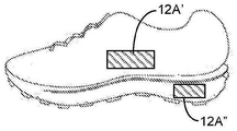


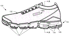


Classifications
-
- C—CHEMISTRY; METALLURGY
- C23—COATING METALLIC MATERIAL; COATING MATERIAL WITH METALLIC MATERIAL; CHEMICAL SURFACE TREATMENT; DIFFUSION TREATMENT OF METALLIC MATERIAL; COATING BY VACUUM EVAPORATION, BY SPUTTERING, BY ION IMPLANTATION OR BY CHEMICAL VAPOUR DEPOSITION, IN GENERAL; INHIBITING CORROSION OF METALLIC MATERIAL OR INCRUSTATION IN GENERAL
- C23C—COATING METALLIC MATERIAL; COATING MATERIAL WITH METALLIC MATERIAL; SURFACE TREATMENT OF METALLIC MATERIAL BY DIFFUSION INTO THE SURFACE, BY CHEMICAL CONVERSION OR SUBSTITUTION; COATING BY VACUUM EVAPORATION, BY SPUTTERING, BY ION IMPLANTATION OR BY CHEMICAL VAPOUR DEPOSITION, IN GENERAL
- C23C14/00—Coating by vacuum evaporation, by sputtering or by ion implantation of the coating forming material
- C23C14/06—Coating by vacuum evaporation, by sputtering or by ion implantation of the coating forming material characterised by the coating material
- C23C14/14—Metallic material, boron or silicon
-
- G—PHYSICS
- G02—OPTICS
- G02B—OPTICAL ELEMENTS, SYSTEMS OR APPARATUS
- G02B5/00—Optical elements other than lenses
- G02B5/18—Diffraction gratings
- G02B5/1809—Diffraction gratings with pitch less than or comparable to the wavelength
-
- A—HUMAN NECESSITIES
- A41—WEARING APPAREL
- A41D—OUTERWEAR; PROTECTIVE GARMENTS; ACCESSORIES
- A41D13/00—Professional, industrial or sporting protective garments, e.g. surgeons' gowns or garments protecting against blows or punches
- A41D13/01—Professional, industrial or sporting protective garments, e.g. surgeons' gowns or garments protecting against blows or punches with reflective or luminous safety means
-
- A—HUMAN NECESSITIES
- A43—FOOTWEAR
- A43B—CHARACTERISTIC FEATURES OF FOOTWEAR; PARTS OF FOOTWEAR
- A43B1/00—Footwear characterised by the material
- A43B1/0027—Footwear characterised by the material made at least partially from a material having special colours
-
- A—HUMAN NECESSITIES
- A43—FOOTWEAR
- A43B—CHARACTERISTIC FEATURES OF FOOTWEAR; PARTS OF FOOTWEAR
- A43B1/00—Footwear characterised by the material
- A43B1/0072—Footwear characterised by the material made at least partially of transparent or translucent materials
-
- B—PERFORMING OPERATIONS; TRANSPORTING
- B32—LAYERED PRODUCTS
- B32B—LAYERED PRODUCTS, i.e. PRODUCTS BUILT-UP OF STRATA OF FLAT OR NON-FLAT, e.g. CELLULAR OR HONEYCOMB, FORM
- B32B37/00—Methods or apparatus for laminating, e.g. by curing or by ultrasonic bonding
- B32B37/02—Methods or apparatus for laminating, e.g. by curing or by ultrasonic bonding characterised by a sequence of laminating steps, e.g. by adding new layers at consecutive laminating stations
- B32B37/025—Transfer laminating
-
- B—PERFORMING OPERATIONS; TRANSPORTING
- B32—LAYERED PRODUCTS
- B32B—LAYERED PRODUCTS, i.e. PRODUCTS BUILT-UP OF STRATA OF FLAT OR NON-FLAT, e.g. CELLULAR OR HONEYCOMB, FORM
- B32B37/00—Methods or apparatus for laminating, e.g. by curing or by ultrasonic bonding
- B32B37/14—Methods or apparatus for laminating, e.g. by curing or by ultrasonic bonding characterised by the properties of the layers
- B32B37/24—Methods or apparatus for laminating, e.g. by curing or by ultrasonic bonding characterised by the properties of the layers with at least one layer not being coherent before laminating, e.g. made up from granular material sprinkled onto a substrate
-
- B—PERFORMING OPERATIONS; TRANSPORTING
- B32—LAYERED PRODUCTS
- B32B—LAYERED PRODUCTS, i.e. PRODUCTS BUILT-UP OF STRATA OF FLAT OR NON-FLAT, e.g. CELLULAR OR HONEYCOMB, FORM
- B32B38/00—Ancillary operations in connection with laminating processes
- B32B38/14—Printing or colouring
-
- B—PERFORMING OPERATIONS; TRANSPORTING
- B44—DECORATIVE ARTS
- B44C—PRODUCING DECORATIVE EFFECTS; MOSAICS; TARSIA WORK; PAPERHANGING
- B44C1/00—Processes, not specifically provided for elsewhere, for producing decorative surface effects
- B44C1/10—Applying flat materials, e.g. leaflets, pieces of fabrics
-
- B—PERFORMING OPERATIONS; TRANSPORTING
- B44—DECORATIVE ARTS
- B44C—PRODUCING DECORATIVE EFFECTS; MOSAICS; TARSIA WORK; PAPERHANGING
- B44C1/00—Processes, not specifically provided for elsewhere, for producing decorative surface effects
- B44C1/16—Processes, not specifically provided for elsewhere, for producing decorative surface effects for applying transfer pictures or the like
- B44C1/165—Processes, not specifically provided for elsewhere, for producing decorative surface effects for applying transfer pictures or the like for decalcomanias; sheet material therefor
-
- B—PERFORMING OPERATIONS; TRANSPORTING
- B44—DECORATIVE ARTS
- B44C—PRODUCING DECORATIVE EFFECTS; MOSAICS; TARSIA WORK; PAPERHANGING
- B44C3/00—Processes, not specifically provided for elsewhere, for producing ornamental structures
-
- C—CHEMISTRY; METALLURGY
- C23—COATING METALLIC MATERIAL; COATING MATERIAL WITH METALLIC MATERIAL; CHEMICAL SURFACE TREATMENT; DIFFUSION TREATMENT OF METALLIC MATERIAL; COATING BY VACUUM EVAPORATION, BY SPUTTERING, BY ION IMPLANTATION OR BY CHEMICAL VAPOUR DEPOSITION, IN GENERAL; INHIBITING CORROSION OF METALLIC MATERIAL OR INCRUSTATION IN GENERAL
- C23C—COATING METALLIC MATERIAL; COATING MATERIAL WITH METALLIC MATERIAL; SURFACE TREATMENT OF METALLIC MATERIAL BY DIFFUSION INTO THE SURFACE, BY CHEMICAL CONVERSION OR SUBSTITUTION; COATING BY VACUUM EVAPORATION, BY SPUTTERING, BY ION IMPLANTATION OR BY CHEMICAL VAPOUR DEPOSITION, IN GENERAL
- C23C16/00—Chemical coating by decomposition of gaseous compounds, without leaving reaction products of surface material in the coating, i.e. chemical vapour deposition [CVD] processes
- C23C16/06—Chemical coating by decomposition of gaseous compounds, without leaving reaction products of surface material in the coating, i.e. chemical vapour deposition [CVD] processes characterised by the deposition of metallic material
-
- G—PHYSICS
- G02—OPTICS
- G02B—OPTICAL ELEMENTS, SYSTEMS OR APPARATUS
- G02B5/00—Optical elements other than lenses
- G02B5/008—Surface plasmon devices
-
- G—PHYSICS
- G02—OPTICS
- G02B—OPTICAL ELEMENTS, SYSTEMS OR APPARATUS
- G02B5/00—Optical elements other than lenses
- G02B5/02—Diffusing elements; Afocal elements
- G02B5/0273—Diffusing elements; Afocal elements characterized by the use
- G02B5/0284—Diffusing elements; Afocal elements characterized by the use used in reflection
-
- B—PERFORMING OPERATIONS; TRANSPORTING
- B32—LAYERED PRODUCTS
- B32B—LAYERED PRODUCTS, i.e. PRODUCTS BUILT-UP OF STRATA OF FLAT OR NON-FLAT, e.g. CELLULAR OR HONEYCOMB, FORM
- B32B2305/00—Condition, form or state of the layers or laminate
- B32B2305/10—Fibres of continuous length
Abstract
As described above, one or more aspects of the present disclosure provide articles having a structural color, and methods of manufacturing articles having a structural color. The present disclosure provides articles that exhibit a structural color through the use of optical elements having one or more reflective layers, wherein the structural color is a visible color, particularly a structural color (e.g., monochromatic, polychromatic, iridescent) produced at least in part by an optical effect (e.g., by scattering, refraction, reflection, interference, and/or diffraction of light at visible wavelengths).
Description
Cross Reference to Related Applications
This application claims priority from a co-pending U.S. patent application entitled "STRUCTURALLY-COLORED ARTICLES AND METHOD FOR MAKING AND USENING STRUCTURALLY-COLORED ARTICLES" filed on 26.6.2019 and designated with application number 62/866,778, and claims priority from a co-pending U.S. patent application entitled "STRUCTURALLY-COLORED ARTICLES AND METHOD FOR MAKING AND USENING STRUCTURALLY-COLORED ARTICLES" filed on 17.10.2019 and designated with application number 62/916,292, both of which are hereby incorporated by reference in their entireties.
Background
Structural color is caused by the physical interaction of light with micro-or nano-features of surfaces and bulk materials, in contrast to the color resulting from the presence of dyes or pigments that absorb or reflect light of a particular wavelength based on the chemical nature of the dye or pigment. Color from dyes and pigments can be problematic in many respects. For example, dyes and pigments and their related chemicals used in the manufacture and incorporation into finished products may not be environmentally friendly.
Brief Description of Drawings
Additional embodiments of the present disclosure will be more readily understood when the following detailed description of the various embodiments of the present disclosure is read in conjunction with the accompanying drawings.
Fig. 1A-1M illustrate various articles of footwear, articles of apparel, articles of athletic equipment, articles of container (container), articles of electronic equipment, and articles of vision protection (vision wear) that include structures according to the present disclosure, while fig. 1N-1P illustrate additional details regarding different types of footwear.
Fig. 2A illustrates a side view of an exemplary inorganic optical element of the present disclosure. Fig. 2B illustrates a side view of an exemplary inorganic optical element of the present disclosure.
The drawings described herein are for illustration purposes only and are not intended to limit the scope of the present disclosure in any way.
Description of the invention
The present disclosure provides articles that exhibit a structural color through the use of optical elements having one or more reflective layers, wherein the structural color is a visible color, particularly a structural color (e.g., monochromatic, polychromatic, iridescent) produced at least in part by an optical effect (e.g., by scattering, refraction, reflection, interference, and/or diffraction of light at visible wavelengths). The article includes an optical element (e.g., a single layer reflector, a single layer filter, a multi-layer reflector, or a multi-layer filter) that includes reflective layers and component layers, where at least one reflective layer (e.g., an intermediate reflective layer) is disposed between a stack of a pair of component layers. The reflective layer has a first side and a second side on opposite sides of the reflective layer. Each stack may include two or more component layers. A first stack is disposed on the first side of the reflective layer and a second stack is disposed on the second side of the reflective layer. The optical element may impart a first structural color from a first side of the optical element and may also impart a second structural color from a second side of the article. In other words, each side of the optical element may exhibit a structural color, the same color, or a different color.
The reflective layer located between the two stacks of component layers may have a minimum percent reflectivity of about 60 percent or greater over a wavelength range of 380 nm to 740 nm under certain conditions. In addition, the reflective layer may also have a maximum percent light transmission of 30 percent or less over a wavelength range of 380 nm to 740 nm under certain conditions.
The optical element may include two or more reflective layers, one of which is an intermediate reflective layer, and one or more other reflective layers may include non-intermediate layers. A non-intermediate reflective layer may be disposed between the component layers in one or both of the first stack and the second stack. Two or more component layers may separate the intermediate reflective layer and the non-intermediate reflective layer. The non-intermediate reflective layer typically has a minimum percent light transmission of about 30 percent or greater under certain conditions.
The reflective layer (e.g., an intermediate reflective layer or a non-intermediate reflective layer) may comprise a metal layer or an oxide layer. The oxide layer may be a metal oxide, a doped metal oxide, or a combination thereof. The metal layer, metal oxide or doped metal oxide may include the following: transition metals, metalloids, lanthanides and actinides, as well as nitrides, oxynitrides, sulfides, sulfates, selenides, tellurides, and combinations of these.
Additionally, depending on the design, the optical element may include an optional textured surface, wherein the optical element is disposed on a surface of the article with the optional textured surface between the optical element and the surface, or wherein the textured surface is part of the optical element. The combination of the optical element and the optional textured surface imparts a first structural color and a second structural color to the article, wherein one or both of the first structural color and the second structural color may be designed to be different than the color of the component of the optical element and/or the underlying material, optionally with or without the application of pigments or dyes to the article. In this way, the structural color can impart an aesthetically appealing color to the article without the need for the use of inks or pigments and without the environmental impact associated with their use.
After the optical element is disposed on the article, the article exhibits a different color than the lower surface of the article without the need to apply additional pigments or dyes to the article. For example, the structure color may be different than the color of the lower surface of the article based on color parameters such as hue, brightness, iridescence type, or any combination thereof. In a particular example, the structural color of the article and the color of the lower surface differ in both hue and type of iridescence, where the structural color is iridescence (e.g., exhibiting two or more different hues when viewed from at least two different angles separated by 15 degrees), and the color of the lower surface is not iridescence.
The article may be a finished product, such as, for example, an article of footwear, an article of apparel, or an article of athletic equipment. The article may be a component of an article of footwear, a component of an article of apparel, or a component of an article of athletic equipment, such as, for example, an upper or sole of an article of footwear, a waistband or sleeve or hood of an article of apparel, a brim of a hat, a portion of a backpack or a panel of a soccer ball, and the like. The optical element can be disposed on the surface such that the reflective layer (and other layers) is parallel or substantially parallel to the surface (e.g., the plane of the reflective layer is parallel to the plane of the surface of the article) (also referred to as an "in-line" or "in-line" configuration), or such that the reflective layer is perpendicular or substantially perpendicular to the surface (also referred to as the optical element being placed "on its side" or "on its side" configuration).
The optical element may be disposed (e.g., attached, adhered, bonded, joined) on a surface of one or more components of the footwear, such as on an upper and/or a sole of the footwear. The optical element may be incorporated into the sole by incorporating it into a cushioning element such as a bladder or foam. The sole and/or upper may be designed such that one or more portions of the structurally colored component are visible in the finished product through a transparent component and the like that includes openings or covers the structurally colored component.
In one aspect, an optical element can be disposed on a surface of a polymer layer of an article, wherein the polymer layer has a minimum percent light transmittance of 30 percent such that structural color can be observed from a side facing the polymer layer. In this way, the optical element can be used to provide two structural colors, one from each side of the optical element in an "in-line" configuration, for example, when the optical element is disposed on an inward-facing surface or an outward-facing surface.
The present disclosure provides an article comprising: an optical element disposed on a surface of a polymer layer of an article, wherein the polymer layer has a minimum percent light transmission of 30 percent (optionally about 20 percent or more, or about 15 percent or more) over a wavelength range of 380 nanometers to 740 nanometers at a first viewing angle of about-15 degrees to 180 degrees or about-15 degrees and +60 degrees under given illumination conditions, wherein the optical element has a first side and a second side opposite the first side, wherein the optical element comprises at least one reflective layer and more than one component layer, wherein the at least one reflective layer comprises an intermediate reflective layer located between the two component layers, wherein the intermediate layer has about 60 percent or more (optionally about 70 percent or more, b) over a wavelength range of 380 nanometers to 740 nanometers at a first viewing angle of about-15 degrees to 180 degrees or about-15 degrees and +60 degrees under given illumination conditions, Optionally about 80 percent or more, or optionally about 90 percent or more, or about 95 percent or more, or about 98 percent or more) and/or a maximum percent light transmission of 30 percent or less (optionally about 20 percent or less, about 15 percent or less, about 10 percent or less, or about 5 percent or less) over a wavelength range of 380 nanometers to 740 nanometers at a first viewing angle of about-15 degrees to 180 degrees or about-15 degrees and +60 degrees under given lighting conditions, wherein the optical element imparts a first structural color to the article from a first side of the optical element, wherein the optical element imparts a second structural color to the article from a second side of the article. The first and second structural colors may be the same or different. Optionally, the at least one reflective layer comprises at least one non-intermediate reflective layer located between the two component layers.
The optical element has a first color measurement having a coordinate L as measured from a first side of the optical element according to the CIE 1976 color space under given lighting conditions at a first viewing angle of about-15 degrees to 180 degrees or about-15 degrees and +60 degrees1A and a1A and b1And the optical element has a second color measurement having a color measured from a second side of the optical elementCoordinate L2A and a2A and b2Wherein Δ E between the first and second color measurementsabGreater than about 2.2, wherein Δ Eab=[(L1*-L2*)2+(a1*-a2*)2+(b1*-b2*)2]1/2Or optionally Δ EabGreater than about 3, or optionally greater than 4, or optionally greater than 5. In this case, the structure colors from each side are distinguishable or different.
The optical element has a first color measurement having a coordinate L as measured from a first side of the optical element according to the CIE 1976 color space under given lighting conditions at a first viewing angle of about-15 degrees to 180 degrees or about-15 degrees and +60 degrees1A and a1A and b1And the optical element has a second color measurement having a second color measurement based on a coordinate L measured from a second side of the optical element 2A and a2A and b2Wherein Δ E between the first and second color measurementsabLess than about 3, wherein Δ Eab=[(L1*-L2*)2+(a1*-a2*)2+(b1*-b2*)2]1/2Or optionally Δ EabLess than about 2.2. In this case, the structural color from each side is the same or nearly the same.
The present disclosure also provides a method comprising: disposing an optical element on a surface of a polymer layer of an article, wherein the polymer layer has a minimum percent light transmittance of 30 percent, wherein the optical element is described above or herein. The present disclosure also provides products of the methods as described above or herein.
The present disclosure provides a method comprising: disposing at least two of the constituent layers onto a surface of a polymer layer of an article to form a first stack, wherein the polymer layer has a minimum percent light transmission of 30 percent (optionally about 20 percent or more, or about 15 percent or more) over a wavelength range of 380 nanometers to 740 nanometers at a first viewing angle of about-15 degrees to 180 degrees, or about-15 degrees and +60 degrees, under given illumination conditions; disposing an intermediate reflective layer onto the first stack, wherein the intermediate reflective layer has a first side surface adjacent to the first stack and a second side surface on a side opposite the first side surface, wherein the intermediate layer has a minimum percent reflectance of about 60 percent or greater (optionally about 70 percent or greater, optionally about 80 percent or greater, or optionally about 90 percent or greater, or about 95 percent or greater, or about 98 percent or greater) over a wavelength range of 380 nm to 740 nm at a first observation angle of between-15 degrees and +60 degrees under given illumination conditions and/or a minimum percent reflectance of 30 percent or less (optionally about 20 percent or less, a first side surface adjacent to the first stack and a second side surface on a side opposite the first side surface at a first observation angle of between-15 degrees and +60 degrees under given illumination conditions over a wavelength range of 380 nm to 740 nm at a first observation angle of between about-15 degrees and 180 degrees or about-15 degrees and +60 degrees, About 15 percent or less, about 10 percent or less, or about 5 percent or less); and disposing at least two of the component layers onto a second side surface of the intermediate layer to form a second stack, wherein the first stack, the intermediate reflective layer, and the second stack comprise optical elements; and wherein the optical element imparts a first structural color to the article from a first side of the optical element, wherein the optical element imparts a second structural color to the article from a second side of the article. The present disclosure also provides an article comprising the product of the method as provided above or herein.
The present disclosure will be better understood upon reading the following numbered aspects, which should not be confused with the claims. In some cases, any of the following numbered aspects may be combined with aspects described elsewhere in the disclosure, and such combinations are intended to form part of the disclosure.
Aspect 1 an article comprising:
an optical element disposed on a surface of a polymer layer of an article, wherein the polymer layer has a minimum percent light transmission of 30 percent (optionally about 20 percent or greater, or about 15 percent or greater) over a wavelength range of 380 nanometers to 740 nanometers at a first viewing angle of about-15 degrees to 180 degrees, or about-15 degrees and +60 degrees, under given illumination conditions, wherein the optical element has a first side and a second side opposite the first side,
wherein the optical element comprises at least one reflective layer and more than one component layer, wherein the at least one reflective layer comprises an intermediate reflective layer located between the two component layers, wherein the intermediate layer has a minimum percent reflectance of about 60 percent or greater (optionally about 70 percent or greater, optionally about 80 percent or greater, or optionally about 90 percent or greater, or about 95 percent or greater, or about 98 percent or greater) over a wavelength range of 380 nm to 740 nm at a first observation angle of about-15 degrees to 180 degrees or about-15 degrees and +60 degrees under given illumination conditions and/or has a minimum percent reflectance of 30 percent or less (optionally about 20 percent or less, a minimum percent reflectance of about 60 percent or greater (optionally about 70 percent or greater, optionally about 80 percent or greater, or about 90 percent or greater, or about 95 percent or greater, or about 98 percent or greater) over a wavelength range of 380 nm to 740 nm at a first observation angle of about-15 degrees to 180 degrees or about-15 degrees and +60 degrees under given illumination conditions, About 15 percent or less, about 10 percent or less, or about 5 percent or less),
Wherein the optical element imparts a first structural color to the article from a first side of the optical element, wherein the optical element imparts a second structural color to the article from a second side of the article.
The article of any of the preceding aspects, wherein the intermediate reflective layer has a first side surface and a second side surface, wherein the second side surface is positioned opposite the first side surface, wherein the first side surface of the intermediate reflective layer is on the first side of the optical element, wherein the second side surface of the intermediate reflective layer is on the second side of the optical element.
Aspect 3 the article according to any one of the preceding aspects, wherein the first structural color and the second structural color are different.
Aspect 4. the article of any of the preceding aspects, wherein the optical element has a first color measurement when measured according to the CIE 1976 color space under given lighting conditions at a first viewing angle of about-15 degrees to 180 degrees, or about-15 degrees and +60 degreesA value, the first color measurement value having a value based on a coordinate L measured from a first side of the optical element1A and a1A and b1And the optical element has a second color measurement having a second color measurement based on a coordinate L measured from a second side of the optical element 2A and a2A and b2Wherein Δ E between the first and second color measurementsabGreater than about 2.2, wherein Δ Eab=[(L1*-L2*)2+(a1*-a2*)2+(b1*-b2*)2]1/2Or optionally Δ EabGreater than about 3, or optionally greater than 4, or optionally greater than 5, the first structural color and the second structural color being different.
Aspect 5 the article of any of the preceding aspects, wherein the optical element has a first color measurement having a coordinate L as measured from a first side of the optical element according to CIE 1976 color space under given lighting conditions at a first viewing angle of about-15 degrees to 180 degrees or about-15 degrees and +60 degrees1A and a1A and b1And the optical element has a second color measurement having a second color measurement based on a coordinate L measured from a second side of the optical element2A and a2A and b2Wherein Δ E between the first and second color measurementsabLess than about 3, wherein Δ Eab=[(L1*-L2*)2+(a1*-a2*)2+(b1*-b2*)2]1/2Or optionally Δ EabLess than about 2.2, the first structural color and the second structural color are the same or substantially the same.
Aspect 6 the article of any of the aspects, wherein the optical element is on an outer surface of the article and visible from the outer surface of the article, or the optical element is on an inner surface of the article and visible from the inner surface of the article.
Aspect 7. the article of any of the preceding aspects, wherein the optical element is a single layer reflector, a single layer filter, a multilayer reflector, or a multilayer filter.
The article of any of the preceding aspects, wherein the optical element has a first stack disposed on the first side surface of the intermediate reflector layer and a second stack disposed on the second side surface of the intermediate reflector layer, wherein the first stack includes component layers and the second stack includes component layers.
Aspect 9 the article of any of the preceding aspects, wherein the intermediate reflective layer is positioned at a first location in the optical element such that light first passes through the first stack of optical elements before impinging on the first side surface of the intermediate reflective layer, and wherein light first passes through the second stack of optical elements before impinging on the second side surface of the intermediate reflective layer.
Aspect 10 the article according to any one of the preceding aspects, wherein the first stack has from 2 to 20 component layers and independently the second stack has from 2 to 20 component layers, wherein optionally each component layer of the first and second stacks independently has a thickness of about one quarter wavelength of the wavelength to be reflected.
The article according to any one of the preceding aspects, wherein each of the component layers of the first stack has a different refractive index, optionally wherein each component layer of the first stack has a thickness of about a quarter wavelength of the wavelength to be reflected; optionally wherein each of the component layers of the second stack has a different refractive index, optionally wherein each component layer of the second stack has a thickness of about one-quarter wavelength of the wavelength to be reflected; optionally wherein one or more of the component layers in the first stack has a different refractive index than one or more of the component layers in the second stack; and optionally wherein one or more of the component layers in the first stack has a different thickness than one or more of the component layers in the second stack.
Aspect 12 the article of any one of the preceding aspects, wherein the first stack and the second stack have the same order, material type and dimensions of the constituent layers from the first side surface and the second side surface, respectively, of the intermediate reflective layer, such that the first stack and the second stack are the same.
The article of any one of the preceding aspects, the intermediate reflective layer having a thickness of at least 10 nanometers (optionally a thickness of at least 30 nanometers, optionally at least 40 nanometers, optionally at least 50 nanometers, optionally at least 60 nanometers, optionally a thickness of from about 10 nanometers to about 100 nanometers, or from about 30 nanometers to about 80 nanometers, or from about 40 nanometers to about 60 nanometers).
Aspect 14 the article of any one of the preceding aspects, wherein the at least one reflective layer comprises at least one non-intermediate reflective layer located between two component layers.
Aspect 15 the article of any of the preceding aspects, wherein the non-intermediate layer is not opaque.
The article of any of the preceding aspects, wherein the non-intermediate layer has a minimum percent light transmission of at least 30 percent, or at least 25 percent, or at least 20 percent over a wavelength range of 380 nanometers to 740 nanometers at a first viewing angle of about-15 degrees to 180 degrees, or about-15 degrees and +60 degrees under given lighting conditions.
The article of any of the preceding aspects, wherein the first stack comprises a first non-intermediate layer, and optionally the second stack comprises a second non-intermediate layer.
The article of any of the preceding aspects, wherein the non-intermediate reflective layer has a thickness of less than 40 nanometers (optionally less than 30 nanometers, optionally less than 20 nanometers, optionally less than 10 nanometers).
The article of any of the preceding aspects, wherein the optical element has a thickness of about 100 nanometers to about 700 nanometers or about 200 nanometers to about 500 nanometers.
Aspect 20 the article of any of the preceding aspects, wherein at least one reflective layer is made of a material selected from a metal or a metal oxide.
Aspect 21 the article of any one of aspects, wherein the at least one reflective layer is made of metal.
The article of any of the preceding aspects, wherein the metal is selected from the group consisting of: titanium, aluminum, silver, zirconium, chromium, magnesium, silicon, gold, platinum, and combinations thereof.
Aspect 23 the article of any of the preceding aspects, wherein the intermediate reflective layer comprises a metal selected from the group consisting of titanium, aluminum, silver, zirconium, chromium, magnesium, silicon, gold, platinum, niobium, oxides of any of these metals, and combinations thereof.
Aspect 24 the article of any of the preceding aspects, wherein the non-intermediate reflective layer comprises a metal selected from the group consisting of titanium, aluminum, silver, zirconium, chromium, magnesium, silicon, gold, platinum, niobium, oxides of any of these metals, and combinations thereof.
Aspect 25 the article of any one of the preceding aspects, wherein the component layers are made of a material selected from the group consisting of: silicon dioxide, titanium dioxide, zinc sulfide, magnesium fluoride, tantalum pentoxide, and combinations thereof.
Aspect 26. a method, comprising:
disposing an optical element on a surface of a polymer layer of the article, wherein the polymer layer has a minimum percent light transmittance of 30 percent, wherein the optical element is described in aspects 1 through 25.
Aspect 27. the method of aspect 26, wherein disposing the optical element includes forming the optical element on a surface of the part, and then disposing the part with the optical element on a surface of the article; optionally wherein the component is a film or textile or molded component.
Aspect 28 the method of any of the preceding aspects, wherein forming the optical element comprises using: physical vapor deposition, electron beam deposition, atomic layer deposition, molecular beam epitaxy, cathodic arc deposition, pulsed laser deposition, sputtering, chemical vapor deposition, plasma enhanced chemical vapor deposition, low pressure chemical vapor deposition, wet chemical techniques, or combinations thereof.
Aspect 29. an article, comprising: the product of the method according to any of the preceding aspects.
Aspect 30. a method, comprising:
disposing at least two of the constituent layers onto a surface of a polymer layer of an article to form a first stack, wherein the polymer layer has a minimum percent light transmission of 30 percent (optionally about 20 percent or more, or about 15 percent or more) over a wavelength range of 380 nanometers to 740 nanometers at a first viewing angle of about-15 degrees to 180 degrees, or about-15 degrees and +60 degrees, under given illumination conditions;
Disposing an intermediate reflective layer onto the first stack, wherein the intermediate reflective layer has a first side surface adjacent to the first stack and a second side surface on a side opposite the first side surface, wherein the intermediate layer has a minimum percent reflectance of about 60 percent or more (optionally about 70 percent or more, optionally about 80 percent or more, or optionally about 90 percent or more, or about 95 percent or more, or about 98 percent or more) over a wavelength range of 380 nm to 740 nm at a first observation angle of about-15 degrees to 180 degrees or about-15 degrees and +60 degrees under given illumination conditions and/or a minimum percent reflectance of 30 percent or less (optionally about 20 percent or less, at least one of about 80 degrees to 180 degrees or about-15 degrees and +60 degrees under given illumination conditions over a wavelength range of 380 nm to 740 nm at a first observation angle of about-15 degrees to 180 degrees or about-15 degrees and +60 degrees, About 15 percent or less, about 10 percent or less, or about 5 percent or less); and
disposing at least two of the constituent layers onto a second side surface of the intermediate layer to form a second stack, wherein the first stack, the intermediate reflective layer, and the second stack comprise optical elements; and is
Wherein the optical element imparts a first structural color to the article from a first side of the optical element, wherein the optical element imparts a second structural color to the article from a second side of the article.
The method of the preceding aspect, wherein disposing at least two of the component layers onto the surface of the polymeric layers of the article to form the first stack further comprises disposing at least one non-intermediate layer on one of the component layers, wherein the non-intermediate layer is between the component layers.
Aspect 32 the method of the preceding aspect, wherein disposing at least two of the component layers onto the surface of the polymeric layers of the article to form the second stack further comprises disposing at least one non-intermediate layer on one of the component layers, wherein the non-intermediate layer is between the component layers.
The method of any of the preceding aspects, wherein disposing each of the constituent layers, the intermediate reflective layer, the non-intermediate reflective layer, or a combination thereof comprises using: physical vapor deposition, electron beam deposition, atomic layer deposition, molecular beam epitaxy, cathodic arc deposition, pulsed laser deposition, sputtering, chemical vapor deposition, plasma enhanced chemical vapor deposition, low pressure chemical vapor deposition, wet chemical techniques, or combinations thereof.
Aspect 34. the method of any of the preceding aspects, wherein the optical element is described in aspects 1 to 25.
Aspect 35. an article, comprising: the product of the method according to any of the preceding aspects.
Aspect 36. the method and/or article of any of the preceding aspects, wherein the polymer layer is colorless, or wherein the polymer layer is transparent and colored.
Aspect 37. the method and/or article of any of the preceding aspects, wherein the polymer layer comprises a thermoplastic material.
The method and/or article of any of the preceding aspects, wherein the thermoplastic material comprises one or more of a thermoplastic polyurethane, a thermoplastic polyether, a thermoplastic polyester, a thermoplastic polyamide, a thermoplastic polyolefin, a thermoplastic copolymer thereof, or a combination thereof.
The method and/or article of any of the preceding aspects, wherein the at least one reflective layer further comprises a textured surface, and the textured surface and the optical elements impart the first structural color, the second structural color, or both.
Aspect 40. the method and/or article of any of the preceding aspects, wherein the surface of the article is a textured surface, wherein the at least one reflective layer is on the textured surface, and the textured surface of the substrate and the optical elements impart the first structural color, the second structural color, or both.
The method and/or article of any of the preceding aspects, wherein the textured surface comprises more than one contour feature and a flat planar region, wherein the contour features extend above the flat region of the textured surface, optionally wherein a size of the contour features, a shape of the contour features, a spacing between more than one contour feature, in combination with the optical element, produces a first structural color, a second structural color, or both, optionally wherein for a particular region the contour features are in a random position relative to each other, optionally wherein a spacing between the contour features is set to reduce a distortion effect of the contour features interfering with each other with respect to the first structural color, the second structural color, or both of the article, optionally wherein the contour features and the flat region result in at least one layer of the optical element having a wave-like topology across the textured surface, wherein there is a planar area between adjacent profile features that is planar with a planar area of the textured surface, wherein the planar area has dimensions relative to the profile features to impart the first structural color, the second structural color, or both, optionally wherein the profile features and the planar area result in each layer of the optical element having an undulating topology across the textured surface.
Aspect 42. the method and/or article of any of the preceding aspects, wherein the first structural color, the second structural color, or both exhibit a single hue or a plurality of different hues when viewed from different viewing angles separated by at least 15 degrees.
Aspect 43. the method and/or article according to any one of the preceding aspects, wherein the article is a fiber.
Aspect 44. the method and/or article according to any of the preceding aspects, wherein the article is a yarn.
Aspect 45. the method and/or article of any of the preceding aspects, wherein the article is a monofilament yarn.
Aspect 46. the method and/or article according to any of the preceding aspects, wherein the article is a textile.
Aspect 47. the method and/or article according to any of the preceding aspects, wherein the article is a knitted textile.
Aspect 48. the method and/or article according to any of the preceding aspects, wherein the article is a non-woven textile.
Aspect 49. the method and/or article according to any one of the preceding aspects, wherein the article is a non-woven synthetic leather.
Aspect 50. the method and/or article according to any one of the preceding aspects, wherein the article is a film.
Aspect 51. the method and/or article of any of the preceding aspects, wherein the article is an article of footwear, a component of footwear, an article of apparel, a component of apparel, an article of athletic equipment, or a component of athletic equipment.
Aspect 52. the method and/or article according to any of the preceding aspects, wherein the article is an article of footwear.
Aspect 53. the method and/or article of any of the preceding aspects, wherein the article is a sole component of an article of footwear.
Aspect 54. the method and/or article of any of the preceding aspects, wherein the article is a foam midsole component (foam midsole component) of an article of footwear.
Aspect 55. the method and/or article according to any of the preceding aspects, wherein the article is an upper component of an article of footwear.
Aspect 56. the method and/or article according to any of the preceding aspects, wherein the article is a knitted upper component of an article of footwear.
Aspect 57. the method and/or article according to any of the preceding aspects, wherein the article is a non-woven synthetic leather upper for an article of footwear.
Aspect 58. the method and/or article of any of the preceding aspects, wherein the article is a bladder comprising a volume of fluid, wherein the bladder has a first bladder wall having a first bladder wall thickness, wherein the first bladder wall has an average wall thickness of 20 milsWith 15cm of nitrogen3/m2Atm · day or less.
Aspect 59. the method and/or article according to any one of the preceding aspects, wherein the article is a capsule and the optical element is optionally on an inner surface of the capsule or optionally the optical element is on an outer surface of the capsule.
Aspect 60. the method and/or article of any preceding aspect, wherein the first structural color, the second structural color, or both are visible to an observer having 20/20 visual acuity and normal color vision at a distance of about 1 meter from the bladder.
Aspect 61. the method and/or article of any preceding aspect, wherein the first structural color, the second structural color, or both have a mono-color phase.
Aspect 62. the method and/or article of any preceding aspect, wherein the first structural color, the second structural color, or both comprise two or more hues.
Aspect 63. the method and/or article of any preceding aspect, wherein the first structural color, the second structural color, or both are iridescent.
Aspect 64. the method and/or article of any preceding aspect, wherein the first structural color, the second structural color, or both have limited iridescence.
Aspect 65. the method and/or article of the preceding aspects, wherein the first structural color, the second structural color, or both have limited iridescence such that when each color visible at each possible viewing angle is assigned to a single color phase selected from the group consisting of primary, secondary, and tertiary colors on a red-yellow-blue (RYB) color wheel, all assigned hues fall into a single color phase group, wherein the single color phase group is one of the following: a) green yellow, yellow and yellow-orange; b) yellow, yellow-orange and orange; c) yellow-orange, orange and orange-red; d) orange red and magenta; e) red, magenta and violet; f) magenta, purple and violet blue; g) violet, violet-blue and blue; h) violet, blue and blue-green; i) blue, cyan and green; and j) cyan, green, and lime.
Aspect 66. the method and/or article of any of the preceding aspects, wherein the optical elements as disposed onto the article (e.g., as may be used for the first structural color, the second structural color, or both) have a coordinate L when measured according to the CIE 1976 color space under given lighting conditions at three viewing angles of about-15 degrees to 180 degrees, or about-15 degrees and +60 degrees, and at least 15 degrees from each other1A and a1A and b1The first observation angle has a first color measurement and has a coordinate L2A and a2A and b2The second observation angle has a second color measurement and has a coordinate L3A and a3A and b3The third observation angle of has a third color measurement, wherein L1Value, L2Value sum L3The values may be the same or different, wherein a1Coordinate value, a2Coordinate values and a3Coordinate values may be the same or different, wherein b1Coordinate value, b2Coordinate values and b3The coordinate values may be the same or different, and a combined therein1Value, a2Value sum a3The range of values is less than about 40% of the total range of possible values of a, or optionally a combined therein1Value, a2Value sum a3The range of values is less than about 30% of the total range of possible values of a, or optionally a combined therein 1Value, a2Value sum a3The range of values is less than about 20% of the total range of possible values of a, or optionally a combined therein1Value, a2Value sum a3The range of values is less than about 10% of the total range of possible values of a.
Aspect 67. the method and/or article of any of the preceding aspects, wherein the optical elements as disposed onto the article (e.g., as may be used for the first structural color, the second structural color, or both) have a coordinate L when measured according to the CIE 1976 color space under given lighting conditions at three viewing angles of about-15 degrees to 180 degrees, or about-15 degrees and +60 degrees, and at least 15 degrees apart from each other1A and a1A and b1The first observation angle has a first color measurement and has a coordinate L2A and a2A and b2The second observation angle has a second color measurement and has a coordinate L3A and a3A and b3The third observation angle of has a third color measurement, wherein L1Value, L2Value sum L3The values may be the same or different, wherein a1Coordinate value, a2Coordinate values and a3Coordinate values may be the same or different, wherein b1Coordinate value, b2Coordinate values and b3Coordinate values may be the same or different, and wherein b is combined1Value, b2Value and b 3The range of values is less than about 40% of the total range of possible b values, or optionally b combined therein1Value, b2Value and b3The range of values is less than about 30% of the total range of possible b values, or optionally b combined therein1Value, b2Value and b3The range of values is less than about 20% of the total range of possible b values, or optionally b combined therein1Value, b2Value and b3The range of values is less than about 10% of the total range of possible b values.
Aspect 68. the method and/or article of any of the preceding aspects, wherein the optical elements as disposed onto the article (e.g., as may be used for the first structural color, the second structural color, or both) have a coordinate L when measured according to the CIE 1976 color space under given lighting conditions at two viewing angles of about-15 degrees to 180 degrees, or about-15 degrees and +60 degrees, and at least 15 degrees from each other1A and a1A and b1The first observation angle has a first color measurement and has a coordinate L2A and a2A and b2The second observation angle of has a second color measurement, wherein L1Value sum L2The values may be the same or different, wherein a1Coordinate values and a2Coordinate values may be the same or different, wherein b1Coordinate values and b 2The coordinate values may be the same or different, and wherein the first color measurement and the second color measurement areΔ E betweenabGreater than or equal to about 100, wherein Δ Eab=[(L1*-L2*)2+(a1*-a2*)2+(b1*-b2*)2]1/2Or optionally wherein Δ E between the first and second color measurementsabLess than or equal to about 80, or optionally wherein Δ E between the first color measurement and the second color measurementabGreater than or equal to about 3, or alternatively less than 3, or less than 2.2, or less than 2.
Aspect 69. the method and/or article of any of the preceding aspects, wherein the optical elements as disposed onto the article (e.g., as may be used for the first structure color, the second structure color, or both) have a coordinate L when measured according to CIELCH color space under given lighting conditions at three viewing angles of about-15 degrees and 180 degrees, or about-15 degrees and +60 degrees, and at least 15 degrees from each other1A and C1A and h1A first viewing angle of DEG has a first color measurement and has a coordinate L2A and C2A and h2A second viewing angle of DEG has a second color measurement and has a coordinate L3A and C3A and h3A third observation angle of DEG has a third color measurement value, wherein L1Value, L2Value sum L3The values may be the same or different, wherein C 1Coordinate value, C2Coordinate values and C3The coordinate values may be the same or different, wherein h1Coordinate value of degree, h2Coordinate value of DEG and h3The coordinate values may be the same or different, and h in combination therein1Value of degree, h2Value of and h3A range of values greater than about 60 degrees, or optionally h combined therein1Value of degree, h2Value of and h3A range of values greater than about 50 degrees, or optionally h combined therein1Value of degree, h2Value of and h3A range of values greater than about 40 degrees, or optionally h combined therein1Value of degree, h2Value of and h3A range of values greater than about 30 degrees, or optionally h combined therein1Value of degree, h2Value of and h3A range of values greater than about 20 degrees, or optionally h combined therein1Value of degree, h2Value of and h3The range of values is less than 10 degrees or less than 5 degrees.
The method and/or article of the preceding aspect, wherein the reflective layer has a minimum percent reflectance of about 60 percent or greater (optionally about 70 percent or greater, optionally about 80 percent or greater, or optionally about 90 percent or greater, or about 95 percent or greater, or about 98 percent or greater) for one of the following wavelength ranges: violet 380-450 nm, blue 450-485 nm, cyan 485-500 nm, green 500-565 nm, yellow 564-590 nm, orange 590-625 nm, red 625-740 nm; optionally wherein for the non-selected range, the minimum reflectance is lower than the minimum reflectance of the selected range.
The method and/or article of the preceding aspect, according to aspect 71, wherein for the unselected ranges, the minimum reflectance is about 10 percent or more, about 20 percent or more, about 30 percent or more, about 40 percent or more, or about 50 percent or more lower than the minimum reflectance of the selected ranges.
Aspect 72 the article and/or method of any of the preceding aspects, wherein the topographical features have at least one dimension greater than 500 microns, and optionally greater than about 600 microns.
Aspect 73. the article and/or method of any one of the preceding aspects, wherein at least one of the length and width of the contour feature is greater than 500 micrometers, or optionally both the length and width of the contour feature are greater than 500 micrometers.
Aspect 74 the article and/or method of any of the preceding aspects, wherein the height of the contour feature may be greater than 50 microns or optionally greater than about 60 microns.
Aspect 75 the article and/or method of any of the preceding aspects, wherein at least one of the length and width of the contour feature is less than 500 microns, or both the length and width of the contour feature are less than 500 microns and the height is greater than 50 microns.
Aspect 76 the article and/or method of any of the preceding aspects, wherein at least one of the length and width of the profile feature is greater than 500 microns, or both the length and width of the profile feature are greater than 500 microns and the height is greater than 50 microns.
Aspect 77 the article and/or method of any one of the preceding aspects, wherein at least one dimension of the topographical features is in the nanometer range and at least one other dimension is in the micrometer range.
The article and/or method of any of the preceding aspects, wherein the nanometers range from about 10 nanometers to about 1000 nanometers and the micrometers range from about 5 micrometers to 500 micrometers.
Aspect 79 the article and/or method of any of the preceding aspects, wherein at least one of the length and width of the profile feature is in the nanometer range and the other of the length and width of the profile feature is in the micrometer range.
Aspect 80 the article and/or method of any one of the preceding aspects, wherein the height of the contour feature is greater than 250 nanometers.
Aspect 81 the article and/or method of any one of the preceding aspects, wherein at least one of the length and width of the contour feature is in the nanometer range and the other is in the micrometer range, wherein the height is greater than 250 nanometers.
Aspect 82 the article and/or method of any one of the preceding aspects, wherein the spatial orientation of the contour features is periodic.
Aspect 83 the article and/or method of any of the preceding aspects, wherein the spatial orientation of the contour features is a semi-random pattern or a set pattern.
Aspect 84. the article and/or method of any of the preceding aspects, wherein the surface of the layer of inorganic optical elements is a substantially three-dimensionally planar surface or a three-dimensionally planar surface.
Having now generally described embodiments of the present disclosure, additional discussion regarding the embodiments will be described in more detail.
The present disclosure is not limited to the particular embodiments described and, thus, may, of course, vary. The terminology used herein is for the purpose of describing particular embodiments only and is not intended to be limiting, as the scope of the present disclosure will be limited only by the appended claims.
When a range of values is provided, each intervening value, to the tenth of the unit of the lower limit unless the context clearly dictates otherwise, between the upper and lower limit of that range and any other stated or intervening value in that stated range is encompassed within the disclosure. The upper and lower limits of these smaller ranges may independently be included in the smaller ranges, and are also encompassed within the disclosure, subject to any specifically excluded limit in the stated range. Where a stated range includes one or both of the limits, ranges excluding either or both of those included limits are also included in the disclosure.
It will be apparent to those of skill in the art upon reading this disclosure that each of the various embodiments described and illustrated herein has discrete components and features that may be readily separated from or combined with the features of any of the other several embodiments without departing from the scope or spirit of the present disclosure. Any recited method may be performed in the order of the recited events or in any other order that is logically possible.
Unless otherwise indicated, embodiments of the present disclosure will employ techniques of material science, chemistry, weaving, polymer chemistry, and the like, which are within the skill of the art. Such techniques are explained fully in the literature.
Unless defined otherwise, all technical and scientific terms used herein have the same meaning as commonly understood by one of ordinary skill in the art of materials science, chemistry, textile, polymer chemistry, and the like. Although methods and materials similar or equivalent to those described herein can be used in the practice or testing of the present disclosure, suitable methods and materials are described herein.
As used in the specification and the appended claims, the singular forms "a", "an" and "the" may include plural referents unless the context clearly dictates otherwise. Thus, for example, reference to "a support" includes more than one support. In this specification and the claims which follow, reference will be made to a number of terms which shall be defined to have the following meanings unless an intent to the contrary is apparent.
The present disclosure provides articles that exhibit a structural color (e.g., structural color articles). An optical element (e.g., a single layer reflector, a single layer filter, a multilayer reflector, or a multilayer filter) disposed on an article can provide a structural color from a first side and a second side of the optical element, wherein the structural color on each side is the same or different. The structural color is a visible color produced at least in part by optical effects, such as by scattering, refraction, reflection, interference, and/or diffraction of light at visible wavelengths. The color of the structure from the first side and the second side may be a single color, multiple colors, or iridescent color. In this way, an article comprising an optical element may provide an attractive visual color from each side of the optical element.
The optical element may include a first stack and a second stack with a reflective layer (e.g., an intermediate reflective layer) between the first stack and the second stack. Each of the first stack and the second stack may comprise two or more component layers and optionally one or more additional reflective layers (e.g., non-intermediate reflective layers). In other words, the optical element may have the following configuration: a first stack/reflective layer/second stack, wherein one or both of the first stack and the second stack may have the following configuration: "n" component layers/optional non-intermediate reflective layers/"m" component layers (n and m can independently be 1 to 30 or more). As also described herein, the optical element may optionally include a textured surface, such as a textured layer and/or a textured structure. Additionally and optionally, the optical element may include one or more layers (e.g., protective layers and the like). The optical element may be incorporated onto one or more components of the article, for example, onto an upper or a sole of the article of footwear when the article is an article of footwear.
The reflective layer may be an intermediate reflective layer or a non-intermediate reflective layer. An intermediate reflective layer is located between the two stacks of component layers, while a non-intermediate reflective layer may be within one or both of the first stack and the second stack. The intermediate reflective layer can have a minimum percent reflectance of about 60 percent or greater, about 70 percent or greater, about 80 percent or greater, about 90 percent or greater, or about 95 percent or greater over a wavelength range of 380 nanometers to 740 nanometers under certain conditions. Additionally, the intermediate reflective layer can also have a maximum percent light transmission of about 30 percent or less, about 20 percent or less, about 10 percent or less, about 5 percent or less over the wavelength range of 380 nanometers to 740 nanometers under certain conditions. The non-intermediate reflective layer can also have a minimum percent light transmission of about 30 percent or greater, about 20 percent or greater, about 10 percent or greater, about 5 percent or greater over the wavelength range of 380 nanometers to 740 nanometers under certain conditions. The conditions for each include a reflective layer (e.g., an intermediate reflective layer and a non-intermediate reflective layer) at a first viewing angle of about-15 degrees to 180 degrees or about-15 degrees and +60 degrees under a given illumination condition. The lighting conditions may be a wide variety of conditions, such as natural lighting (e.g., daylight, dawn, dusk), artificial lighting (such as outdoor (e.g., street lamps, car headlights, etc.), indoor (e.g., indoor lighting)), or a combination of natural and artificial lighting, either indoor or outdoor.
Greater than 50 percent of the minimum percent light transmission is opaque, 20 to 50 percent of the minimum percent light transmission is translucent, and less than 20 percent of the minimum percent light transmission is transparent.
The optical element may be disposed on the surface in a variety of ways. For example, the optical element may be disposed on the surface such that each of the layers of the optical element is parallel or substantially parallel to the surface (e.g., "in-line" disposed). In other words, the length and width of the layers of the optical element define a plane, while the thickness of the layers is the smallest dimension. In this regard, the first side of the optical layer may be disposed on a surface that is not opaque such that light may pass through the surface to reach the optical element. As a result, light passing through the surface that irradiates the first side of the optical element may produce a first structural color, while light that irradiates the second side of the optical element may produce a second structural color. In one aspect, the surface may be a polymer layer that is not opaque. The polymer layer may be transparent or translucent. The polymer layer can have a minimum percent light transmission of about 30 percent or greater, about 20 percent or greater, or about 15 percent or greater. In other words, sufficient light may pass through the polymer layer under lighting conditions (e.g., daylight, dusk, indoor living lighting conditions, and the like) to produce the first structural color. The polymer layer may comprise one or more polymers selected from the group consisting of: polyesters, polyethers, polyamides, polyurethanes, polyolefin copolymers of each, and combinations thereof.
In another example, each of the layers of the optical element is perpendicular or substantially perpendicular to the surface. In other words, the optical element may be considered to be placed "on its side" on a surface. In this way, light impinging the first side of the optical element produces a first structural color on the first side of the optical element, and light impinging the second side of the optical element produces a second structural color on the second side of the optical element. In either configuration, the optical element may produce an aesthetically pleasing appearance.
In one or more embodiments of the present disclosure, the surface of the article comprises an optical element, and optionally is a textured surface, wherein the optical element and optionally textured surface impart a structural color (e.g., monochromatic, polychromatic, iridescent). Depending on the design, the optional textured surface may be disposed between the optical element and the surface, or may be part of the optical element.
The present disclosure has been described generally, with additional details provided. The optical element may comprise an intermediate reflective layer between the first stack and the second stack. The intermediate reflective layer can have a thickness of at least 10 nanometers, optionally at least 30 nanometers, at least 40 nanometers, at least 50 nanometers, at least 60 nanometers, at least 100 nanometers, at least 150 nanometers, optionally a thickness of from about 10 nanometers to about 250 nanometers or more, from about 10 nanometers to about 200 nanometers, from about 10 nanometers to about 150 nanometers, from about 10 nanometers to about 100 nanometers, or from about 30 nanometers to about 80 nanometers, or from about 40 nanometers to about 60 nanometers. For example, the thickness of the intermediate reflective layer may be about 30 to 150 nanometers.
The optical element may include one or more non-intermediate reflective layers. A non-intermediate reflective layer may be present in one or both of the first stack and the second stack. The non-intermediate reflective layer may have a thickness of less than 40 nanometers, optionally less than 30 nanometers, optionally less than 20 nanometers, optionally less than 10 nanometers. For example, the thickness of the non-intermediate layer may be 20 nanometers to 30 nanometers. The non-intermediate reflective layer is not opaque.
The reflective layer (e.g., an intermediate reflective layer or a non-intermediate reflective layer) may comprise a metal layer or an oxide layer. The oxide layer may be a metal oxide, a doped metal oxide, or a combination thereof. The metal layer, metal oxide or doped metal oxide may include the following: transition metals, metalloids, lanthanides and actinides, as well as nitrides, oxynitrides, sulfides, sulfates, selenides, tellurides, and combinations of these. The metal layer may be titanium, aluminum, silver, zirconium, chromium, magnesium, silicon, gold, platinum, and combinations thereof. The metal oxide can include titanium oxide, silver oxide, aluminum oxide, silicon dioxide, tin dioxide, chromium oxide, iron oxide, nickel oxide, silver oxide, cobalt oxide, zinc oxide, platinum oxide, palladium oxide, vanadium oxide, molybdenum oxide, lead oxide, and combinations and doped versions of each. In some aspects, the reflective layer can consist essentially of a metal oxide. In some aspects, the reflective layer can consist essentially of titanium dioxide. The metal oxide can be doped with water, inert gases (e.g., argon), reactive gases (e.g., oxygen or nitrogen), metals, small molecules, and combinations thereof. In some aspects, the reflective layer may consist essentially of a doped metal oxide or a doped metal oxynitride or Both of them are composed. In one aspect, the reflective layer may be made of Ti or TiTiOx(x-1-2). Ti layer or TiOxThe layer can have a density of about 3 to 6 grams per cubic centimeter, about 3 to 5 grams per cubic centimeter, about 4 to 5 grams per cubic centimeter, or 4.5 grams per cubic centimeter.
The material of the metal layer may be selected based on the desired structural color to be produced. The material is selected to reflect some wavelengths more than others. In this way, the material of the reflective layer may be selected based on the desired structural color. Optical elements including reflective layers (e.g., intermediate reflective layers and/or non-intermediate reflective layers) may have a minimum percent reflectivity for one or more of the following wavelength ranges: violet 380 nm to 450 nm, blue 450 nm to 485 nm, cyan 485 nm to 500 nm, green 500 nm to 565 nm, yellow 564 nm to 590 nm, orange 590 nm to 625 nm or red 625 nm to 740 nm. The reflective layer may have a minimum percent reflectivity for one or more wavelength widths (e.g., about 10 nanometers, about 20 nanometers, about 30 nanometers, about 40 nanometers, about 50 nanometers, about 60 nanometers, about 75 nanometers, or about 100 nanometers) in a range from 380 nanometers to 740 nanometers. For ranges not selected in a particular configuration, the minimum reflectance is lower than the minimum reflectance for the selected range, e.g., the minimum reflectance is about 10 percent or more, about 20 percent or more, about 30 percent or more, about 40 percent or more, or about 50 percent or more lower than the minimum reflectance for the selected range. In one aspect, the reflective layer can be Al or AlO xWherein the structural color is iridescent. In another example, the reflective layer may be Ti or TiOxWherein the structural color can be one or more blue hues or one or more green hues or a combination thereof.
The reflective layer (e.g., an intermediate reflective layer) can be a coating on the surface of the article. The coating may be chemically bonded (e.g., covalently bonded, ionically bonded, hydrogen bonded, and the like) to the surface of the article. It has been found that the coating is well bonded to surfaces made of polymeric materials. In an example, the surface of the article may be made of a polymeric material, such as polyurethane, including Thermoplastic Polyurethane (TPU), such as those described herein. Additional details regarding the optical elements and reflective layers are provided herein.
In embodiments, the structural color is not used in combination with a pigment and/or dye. In another aspect, the structural color is used in combination with a pigment and/or dye, but the structural color is not the same color, shade, and/or hue as the pigment and/or dye. In this regard, the structural color is the product of the textured surface, the optical element, and the pigment and/or dye.
In embodiments, the structural color is used in combination with a pigment and/or dye to enhance the color of the pigment and/or dye relative to the color of the pigment and/or dye or to enhance the hue, tint, shade or hue associated with the pigment and/or dye.
The article may be an article of manufacture or a component of an article. Articles of manufacture may include footwear, apparel (e.g., shirts, sweaters, pants, shorts, gloves, eyeglasses, socks, hat bands, hats, jackets, undergarments), enclosures (e.g., backpacks, bags), and upholstery for furniture (e.g., chairs, couches, vehicle seats), bedding (e.g., sheets, blankets), tablecloths, towels, flags , tents, sails, and parachutes, or components of any of these articles. In addition, the optical elements may be used with or disposed on textiles or other articles such as striking devices (e.g., clubs, rackets, sticks, bats, golf clubs, paddles, and the like), athletic equipment (e.g., golf bags, baseball and football gloves, soccer ball restraining structures), protective equipment (e.g., mats, helmets, guards, visors, and the like), locomotive equipment (e.g., bicycles, motorcycles, skateboards, cars, trucks, boats, surfboards, skis, and the like), balls or hockey balls for a variety of sports, fishing or hunting equipment, furniture, electronic equipment, building materials, eye guards, clocks, jewelry, and the like.
The article may be an article of footwear. The article of footwear may be designed for a variety of uses, such as athletic use, military use, work-related use, recreational use, or recreational use. Primarily, the article of footwear is intended for outdoor use on unpaved surfaces (partially or wholly), such as on ground surfaces including one or more of grass, turf, gravel, sand, dirt, clay, mud, pavement, and the like, whether as athletic performance surfaces or as general outdoor surfaces. However, the article of footwear may also be desirable for indoor applications, such as, for example, indoor sports that include a dirt playing surface (e.g., indoor baseball fields with dirt infields).
In particular, the article of footwear may be designed for indoor or outdoor athletic activities, such as international football (football)/soccer (soccer), golf, american football, rugby, baseball, running, track and field, cycling (e.g., road cycling and mountain cycling), and similar athletic activities. The article of footwear may optionally include traction elements (e.g., lugs, cleats, studs and nails, and tread patterns) to provide traction on soft and smooth surfaces, wherein the components of the present disclosure may be used or applied between or among traction elements, and optionally on the sides of the traction elements but on the surface of the traction elements that contacts the ground or surface. Cleats, spikes, and nails are commonly included in footwear designed for sports such as international/soccer, golf, american football, rugby, baseball, and the like, which are often performed on unpaved surfaces. Lugs and/or enhanced tread patterns are typically included in footwear including boots that are designed for use in harsh outdoor conditions, such as off-road running, hiking, and military use.
In particular, the article may be an article of apparel (i.e. a garment). The article of apparel may be an article of apparel designed for athletic or leisure activities. The article of apparel may be an article of apparel designed to provide protection from elements (e.g., wind and/or rain) or from impact.
In particular, the article may be an item of sports equipment. The article of athletic equipment may be designed for indoor or outdoor athletic activities, such as international football/soccer, golf, american football, rugby, baseball, running, track and field, cycling (e.g., road and mountain biking), and the like.
Fig. 1A-1M illustrate footwear, apparel, athletic equipment, content, electronic equipment, and visual protection that include structures (e.g., optical elements, optionally textured surfaces) of the present disclosure. The structure may include optical elements in an "in-line" configuration and/or "at the sides thereof" configuration. The structure including the optical elements is represented by hashed regions 12A '/12M ' -12A "/12M '. The location of the structure is provided merely to indicate one possible area where the structure may be located. Further, two locations are illustrated in some figures and one location is illustrated in other figures, but this is for illustration purposes only, as the article may comprise one or more structures, where size and location may be determined based on the article. The structure located on each article may represent a number, letter, symbol, design, logo, graphical indicia, icon, trademark, or the like.
Fig. 1n (a) and 1n (b) illustrate perspective and side views of an article of footwear 100 that includes a sole structure 104 and an upper 102. Structures including inorganic optical elements are denoted by 122a and 122 b. Sole structure 104 is secured to upper 102 and sole structure 104 extends between the foot and the ground when article of footwear 100 is worn. The primary elements of sole structure 104 are a midsole 114 and an outsole 112. Midsole 114 is secured to a lower area of upper 102 and may be formed from a polymer foam or another suitable material. In other configurations, midsole 114 may incorporate fluid-filled chambers, plates, moderators, and/or other elements that further attenuate forces, enhance stability, or influence the motions of the foot. Outsole 112 is secured to a lower surface of midsole 114 and may be formed from, for example, a wear-resistant rubber material that is textured to impart traction. Upper 102 may be formed from a variety of elements (e.g., laces, tongues, collars) that combine to provide a structure for securely and comfortably receiving a foot. Although the configuration of upper 102 may vary significantly, the various elements generally define a void within upper 102 for receiving and securing a foot relative to sole structure 104. The surface of the void within upper 102 is shaped to receive the foot and may extend over the instep and toe areas of the foot, along the medial and lateral sides of the foot, under the foot, and around the heel area of the foot. Upper 102 may be formed from one or more materials stitched or bonded together, such as textiles, polymer foam, leather, synthetic leather, and the like. While this configuration of sole structure 104 and upper 102 provides an example of a sole structure that may be used in connection with an upper, a variety of other conventional or nonconventional configurations of sole structure 104 and/or upper 102 may also be used. Accordingly, the configuration and features of sole structure 104 and/or upper 102 may vary significantly.
Fig. 1o (a) and 1o (b) illustrate perspective and side views of an article of footwear 130 that includes a sole structure 134 and an upper 132. Structures comprising inorganic optical elements are denoted by 136a and 136b/136 b'. Sole structure 134 is secured to upper 132 and sole structure 134 extends between the foot and the ground when article of footwear 130 is worn. Upper 132 may be formed from a variety of elements (e.g., laces, tongues, collars) that combine to provide a structure for securely and comfortably receiving a foot. Although the configuration of upper 132 may vary significantly, the various elements generally define a void within upper 132 for receiving and securing a foot relative to sole structure 134. The surface of the void within upper 132 is shaped to receive the foot and may extend over the instep and toe areas of the foot, along the medial and lateral sides of the foot, under the foot, and around the heel area of the foot. Upper 132 may be formed from one or more materials stitched or bonded together, such as textiles including natural and synthetic leather, molded polymer components, polymer foams, and the like.
The primary elements of sole structure 134 are a forefoot component 142, a heel component 144, and an outsole 146. Each of forefoot component 142 and heel component 144 is secured, directly or indirectly, to a lower area of upper 132 and is formed from a polymer material that encapsulates a fluid, which may be a gas, a liquid, or a gel. For example, during walking and running, forefoot component 142 and heel component 144 compress between the foot and the ground, thereby attenuating ground reaction forces. That is, forefoot component 142 and heel component 144 are inflated and may be pressurized with a fluid to cushion the foot. Outsole 146 is secured to lower regions of forefoot component 142 and heel component 144, and may be formed of a wear-resistant rubber material that is textured to impart traction. Forefoot component 142 may be made of one or more polymers (e.g., one or more layers of polymer film) that form more than one chamber containing a fluid, such as a gas. More than one chamber may be independent or fluidly interconnected. Similarly, heel component 144 may be made from one or more polymers (e.g., one or more layers of polymer film) that form more than one chamber that contains a fluid, such as a gas, and that may also be separate or fluidly interconnected. In some configurations, sole structure 134 may include a foam layer that extends between upper 132 and one or both of forefoot component 142 and heel component 144, or foam elements may be located within indentations (indentations) in lower regions of forefoot component 142 and heel component 144, for example. In other configurations, sole structure 132 may incorporate plates, moderators, lasting elements, or motion control members, for example, to further attenuate forces, enhance stability, or influence the motion of the foot. Although the depicted configurations of sole structure 134 and upper 132 provide examples of sole structures that may be used in connection with an upper, a variety of other conventional or nonconventional configurations of sole structure 134 and/or upper 132 may also be used. Accordingly, the configuration and features of sole structure 134 and/or upper 132 may vary significantly
Fig. 1o (c) is an a-a cross-sectional view depicting upper 132 and heel component 144. Optical element 136b may be disposed on an outer wall of heel component 144, or alternatively or optionally optical element 136 b' may be disposed on an inner wall of heel component 144.
Fig. 1p (a) and 1p (b) illustrate perspective and side views of an article of footwear 160 that includes traction elements 168. Structures including inorganic optical elements are denoted by 172a and 172 b. Article of footwear 160 includes an upper 162 and a sole structure 164, with upper 162 secured to sole structure 164. Sole structure 164 may include one or more of a toe plate 166a, a middle plate 166b, and a heel plate 166 c. The plate may include one or more traction elements 168, or traction elements may be applied directly to the ground-facing surface of the article of footwear. As shown in fig. 1p (a) and 1p (b), traction elements 168 are cleats, but may include lugs, cleats, studs and nails, and tread patterns to provide traction on soft and smooth surfaces. Generally, cleats, spikes, and nails are typically included in footwear designed for sports such as international/soccer, golf, american football, rugby, baseball, and the like, while lugs and/or enhanced tread patterns are typically included in footwear (not shown) including boots designed for use in harsh outdoor conditions such as cross-country running, hiking, and military use. Sole structure 164 is secured to upper 162 and sole structure 164 extends between the foot and the ground when article of footwear 160 is worn. Upper 162 may be formed from a variety of elements (e.g., laces, tongues, collars) that combine to provide a structure for securely and comfortably receiving a foot. Although the configuration of upper 162 may vary significantly, the various elements generally define a void within upper 162 for receiving and securing a foot relative to sole structure 164. The surface of the void within upper 162 is shaped to receive the foot and extends over the instep and toe areas of the foot, along the medial and lateral sides of the foot, under the foot, and around the heel area of the foot. Upper 162 may be formed from one or more materials that are stitched or bonded together, such as textiles including natural and synthetic leather, molded polymer components, polymer foams, and the like. In other aspects not depicted, sole structure 164 may incorporate foam, one or more fluid-filled chambers, plates, moderators, or other elements that further attenuate forces, enhance stability, or influence the motion of the foot. Although the depicted configurations of sole structure 164 and upper 162 provide examples of sole structures that may be used in connection with an upper, a variety of other conventional or nonconventional configurations of sole structure 164 and/or upper 162 may also be used. Accordingly, the configuration and features of sole structure 164 and/or upper 162 may vary significantly.
As already described herein, the structural color (e.g., the first structural color and the second structural color) may comprise one of a number of colors. The "color" of an item as perceived by an observer may be different from the actual color of the item, as the color perceived by the observer is determined by: the optical element may absorb, refract, interfere with, or otherwise alter the light reflected by the article due to the actual color of the article due to its presence; the ability of an observer to detect the wavelength of light reflected by the article; the wavelength of the light used to illuminate the item, and other factors such as the color of the environment of the item and the type of incident light (e.g., sunlight, fluorescent light, and the like). As a result, the color of the object as perceived by the viewer may be different from the actual color of the article.
Conventionally, man-made objects are imparted with color by applying colored pigments or dyes to the object. More recently, methods have been developed to impart "structural colors" to artificial objects. Structural color is the color produced at least in part by the microstructured surface interfering with the visible light of the contact surface. Unlike colors caused by absorption or emission of visible light by coloring substances, structural colors are colors caused by physical phenomena including scattering, refraction, reflection, interference, and/or diffraction of light. For example, optical phenomena that impart color to structures may include multilayer interference, thin film interference, refraction, dispersion, light scattering, mie scattering, diffraction, and diffraction gratings. In aspects described herein, the structural color imparted to the article may be visible to an observer having 20/20 visual acuity and normal color vision at a distance of about 1 meter from the article.
As described herein, the structural color is at least partially produced by the optical element, as opposed to the color produced by the pigment and/or dye alone. The color of the structurally colored article may be due solely to the structural color (i.e., the article, the colored portion of the article, or the colored outer layer of the article may be substantially free of pigments and/or dyes). The structural color may also be used in combination with pigments and/or dyes, for example, to change all or a portion of the structural color.
"hue" is generally used to describe a property of a color that is distinguishable based on the dominant wavelength of visible light, and is generally described using terms such as magenta, red, orange, yellow, green, cyan, blue, indigo, violet, etc., or may be described as being associated with (e.g., similar or dissimilar to) one of these colors. The hue of a color is generally considered to be independent of the intensity or brightness of the color. For example, in the munsell color system, the properties of a color include hue, darkness (brightness), and chroma (color purity). A particular hue is typically associated with a particular range of wavelengths in the visible spectrum: wavelengths in the range of about 700 to 635 nanometers are associated with red, a range of about 635 to 590 nanometers is associated with orange, a range of about 590 to 560 nanometers is associated with yellow, a range of about 560 to 520 nanometers is associated with green, a range of about 520 to 490 nanometers is associated with cyan, a range of about 490 to 450 nanometers is associated with blue, and a range of about 450 to 400 nanometers is associated with violet.
The color (including hue) of the article as perceived by an observer may be different from the actual color of the article. The color as perceived by an observer depends not only on the physical properties of the article, but also on the environment of the article, and the characteristics of the perceived eyes and brain. For example, as the color perceived by an observer is determined by the actual color of the item (e.g., the color of light exiting the surface of the item), the ability of the observer to detect the wavelengths of light reflected or emitted by the item, the wavelengths of light used to illuminate the item, and other factors such as the color of the environment of the item and the type of incident light (e.g., sunlight, fluorescent light, and the like). As a result, the color of the object as perceived by the viewer may be different from the actual color of the article.
When used in the context of a structural color (e.g., a first structural color and/or a second structural color), one can characterize the hue of a structurally colored article (i.e., an article that has been structurally colored by incorporating an optical element into the article) based on the wavelengths at which the structurally colored portion of the article absorbs and reflects (e.g., linearly and non-linearly) light. While the optical element may impart the first structural color, the presence of the optional textured surface may change the structural color. Other factors such as coatings or transparent elements may further alter the perceived color of the structure. The hues of the structurally colored article may comprise any one of the hues described herein as well as any other hue or combination of hues. Structural colors may be referred to as "mono-hues" (i.e., hues that remain substantially the same regardless of angle of observation and/or illumination) or "multi-hues" (i.e., hues that vary depending on angle of observation and/or illumination). The multi-hue structure color may be iridescent (i.e., the hue gradually changes within two or more hues as the angle of observation or illumination changes). The hue of iridescent polychrome structure colors can gradually change across all hues in the visible spectrum (e.g., like a "rainbow") as the angle of observation or illumination changes. The hue of an iridescent polychrome structural color may gradually change across a limited number of hues in the visible spectrum as the angle of observation or illumination changes, in other words, one or more hues in the visible spectrum (e.g., red, orange, yellow, etc.) are not observable in the structural color as the angle of observation or illumination changes. For a single hue structure color, there may be only one hue or substantially one hue in the visible spectrum. The hues of the multi-hue structure colors may change more abruptly between a limited number of hues (e.g., between 2-8 hues, or between 2-4 hues, or between 2 hues) as the angle of observation or illumination changes.
The structural color may be a multi-hue structural color in which two or more hues are imparted by the structural color.
The structural color can be an iridescent multi-hue structural color in which the hue of the structural color varies over a wide variety of hues (e.g., 4, 5, 6, 7, 8, or more hues) when viewed at a single viewing angle, or when viewed from two or more different viewing angles that are at least 15 degrees apart from one another.
The structural color can be a limited iridescent polychrome structural color in which the hues of the structural color vary or significantly vary (e.g., about 90 percent, about 95 percent, or about 99 percent) over a limited number of hues (e.g., 2 hues or 3 hues) when viewed from two or more different viewing angles that are at least 15 degrees apart from each other. In some aspects, structural colors with limited iridescence are limited to two, three or four hues selected from: red, yellow and blue RYB primary colors, optionally red, yellow, blue, green, orange and violet RYB primary and secondary colors, or optionally red, yellow, blue, green, orange violet, greenish yellow, yellow orange, orange red, magenta, violet blue and cyan RYB primary, secondary and tertiary colors.
The structural color can be a mono-hue, angle-independent structural color, wherein the hue, and lightness, or hue, lightness, and chroma, of the structural color are independent of the angle of observation or substantially independent of the angle of observation (e.g., about 90 percent, about 95 percent, or about 99 percent). For example, the single-hue, angle-independent structural colors may exhibit the same hue or substantially the same hue (e.g., single-hue structural colors) when viewed from at least 3 different angles that are at least 15 degrees apart from each other.
The imparted structural colors may be structural colors having limited iridescence such that when each color viewed at each possible viewing angle is assigned to a single color phase selected from the group consisting of primary, secondary and tertiary colors on a red-yellow-blue (RYB) color wheel, all assigned hues fall into a single color phase group for a single structural color, wherein the single color phase group is one of: a) green yellow, yellow and yellow-orange; b) yellow, yellow-orange and orange; c) yellow-orange, orange and orange-red; d) orange red and magenta; e) red, magenta and violet; f) magenta, purple and violet blue; g) violet, violet-blue and blue; h) violet, blue and blue-green; i) blue, cyan and green; and j) cyan, green, and lime. In other words, in this example of limited iridescence, the hue (or hue and darkness, or hue, darkness and chroma) imparted by the structural color varies depending on the angle from which the structural color is viewed, but the hue of each different color viewed at different viewing angles varies within a limited number of possible hues. The color phase visible at each viewing angle may be assigned to a primary (primary hue), secondary (secondary hue) or tertiary (tertiary hue) on a red-yellow-blue (RYB) color wheel (i.e., a group of color phases consisting of red, yellow, blue, green, orange-violet, green-yellow, yellow-orange, orange-red, magenta-violet, violet-blue and cyan). For example, when each observed hue is classified as one of red, yellow, blue, green, orange-violet, green-yellow, yellow-orange, orange-red, magenta-violet, violet-blue, and cyan, the assigned list of hues includes no more than one, two, or three hues selected from the list of RYB primary, secondary, and tertiary hues, although more than one different color is observed as the angle of observation shifts. In some examples of limited iridescence, all assigned hues fall into a single color phase group selected from the group of hue phases a) -j), each color phase group comprising three adjacent hues on a color wheel of the primary, secondary and tertiary colors of the RYB. For example, all assigned hues may be a single hue (e.g., blue) in the hue group h), or some assigned hues may represent two hues (e.g., violet-blue and blue) in the hue group h), or may represent three hues (e.g., violet-blue, blue and blue-green) in the hue group h).
Similarly, other properties of the structural color, such as the brightness of the color, the saturation of the color, and the purity of the color, among others, may be substantially the same regardless of the angle of observation or illumination, or may vary depending on the angle of observation or illumination. The structural color may have a matte appearance, a glossy appearance, or a metallic appearance, or a combination thereof.
As discussed above, the color (including hue) of a structurally colored article (e.g., an article including a structural color) may vary depending on the angle at which the structurally colored article is viewed or illuminated. One or more hues of the article may be determined by viewing the article or illuminating the article at a variety of angles using constant lighting conditions. As used herein, an "angle" of illumination or observation is an angle measured from an axis or plane normal to the surface. The viewing angle or illumination angle may be set between about 0 degrees and 180 degrees. The viewing or illumination angles may be set at 0 degrees, 15 degrees, 30 degrees, 45 degrees, 60 degrees, and-15 degrees, and the color may be measured using a colorimeter or spectrophotometer (e.g., Konica Minolta) that focuses on a particular area of the article to measure the color. The viewing angle or the illumination angle may be set to 0 degrees, 15 degrees, 30 degrees, 45 degrees, 60 degrees, 75 degrees, 90 degrees, 105 degrees, 120 degrees, 135 degrees, 150 degrees, 165 degrees, 180 degrees, 195 degrees, 210 degrees, 225 degrees, 240 degrees, 255 degrees, 270 degrees, 285 degrees, 300 degrees, 315 degrees, 330 degrees, and 345 degrees, and the color may be measured using a colorimeter or a spectrophotometer. In the specific example of a multi-hue article colored using only structural colors, the hue measured for the article when measured at 0, 15, 30, 45, 60, and-15 degrees consists of: "blue" at three of these measurement angles, "cyan" at two of these measurement angles, and "violet" at one of these measurement angles.
In other embodiments, the color (including hue, darkness and/or chroma) of the structurally colored article does not substantially change, if at all, depending on the angle at which the article is viewed or illuminated. In cases such as this, the structural color may be an angle-independent structural color in that the observed hue, and darkness, or hue, darkness, and chroma, are substantially independent of the angle of observation or independent of the angle of observation.
There are a variety of methodologies for defining color coordinate systems. One example is the L x a b color space, where L x is the luminance value for a given lighting condition, and a and b are the values of the color opposites dimension based on CIE coordinates (CIE 1976 color space or CIELAB). In embodiments, an article having a structural color (e.g., a first structural color and/or a second structural color) may be considered to have a "single" color when the change in the measured color of the article at three or more measured viewing or illumination angles selected from 0, 15, 30, 45, 60, and-15 measured viewing or illumination angles is within about 10% or within about 5% of the total number of a or b coordinates of the L a b numerical range (CIE 1976 color space). In certain embodiments, a color is considered a different color when the measured and assigned values differ by at least 5 percent of the numerical range of a and b coordinates, or by at least 10 percent of the numerical range of a and b coordinates in the L a b system. The structurally colored article can have a variation in the total number of values of the a-coordinates or b-coordinates of the L a b range of values (CIE 1976 color space) of less than about 40%, or less than about 30%, or less than about 20%, or less than about 10% at three or more measured viewing or illumination angles.
Another example of a color value range is the CIELCH color space, where L is the luminance value, C is the chromaticity value, and h represents the hue as an angular measure for a given lighting condition. In embodiments, a structural color (e.g., a first structural color and/or a second structural color) may be considered to have a "single" color when the difference in the h ° angular coordinate of the measured color of the article in the CIELCH color space at three or more measured viewing angles or illumination angles selected from the group consisting of 0 degrees, 15 degrees, 30 degrees, 45 degrees, 60 degrees, and-15 degrees is less than 10 degrees or less than 5 degrees. In certain embodiments, a structural color (e.g., a first structural color and/or a second structural color) is considered a different color when the measured and assigned values vary by at least 45 degrees from the h ° measurement in the CIELCH system. The structurally colored article can have a variation in the h ° measurement of the CIELCH system of 10 degrees to about 60 degrees, 10 degrees to about 50 degrees, or 10 degrees to about 40 degrees, 10 degrees to about 30 degrees, or 10 degrees to about 20 degrees at three or more measured viewing or illumination angles. The structurally colored article may have a variation in the h ° measurement of the CIELCH system of about 1 to 10 degrees, about 1 to 7.5 degrees, or 1 to about 2 degrees at three or more measured viewing or illumination angles.
Another system for characterizing color includes the "PANTONE" matching system (PANTONE LLC, Carlstadt, new jersey, usa), which provides a visual color standard system that provides an accurate method for selecting, specifying, diffusing, and matching colors through any medium. In an example, a structurally colored article having a structural color can be considered to have a "single" color when the color measured on the article at three or more measured viewing or illumination angles selected from 0 degrees, 15 degrees, 30 degrees, 45 degrees, 60 degrees, and-15 degrees is within a certain number of adjacent standard values, for example within 20 adjacent PANTONE standard values.
The change or difference in color between two measurements and/or two colors (e.g., the first structural color and/or the second structural color) in the CIELAB space can be determined mathematically. For example, the first measurement (e.g., the first structure color) has a coordinate L1*、a1A and b1And the second measurement (e.g., second structure color) has a coordinate of L2*、a2A and b2*. The total difference between these two measurements over the CIELAB value range can be expressed as Δ E ×abIt is calculated as follows: delta Eab=[(L1*-L2*)2+(a1*-a2*)2+(b1*-b2*)2]1/2. In general, if two colors (e.g., a first structural color and/or a second structural color) have Δ E less than or equal to 1 abThe difference in color is imperceptible to the human eye and if two colors (e.g., the first structural color and the second structural color) are present/or second structural color) has a Δ E > 100abThen the color is considered the opponent color, and a Δ E of about 2-3abIs considered to be a threshold for perceptible color differences. In certain embodiments, Δ E between three or more measured viewing or illumination angles selected from the group consisting of 0 degrees, 15 degrees, 30 degrees, 45 degrees, 60 degrees, and-15 degreesabFrom about 3 to 60, or about 3 to 50, or about 3 to 40, or about 3 to 30, a structurally colored article having a structural color can be considered to have two colors. The structurally colored article can have a Δ E between two or more measured viewing or illumination angles of about 3 to about 100, or about 3 to about 80, or about 3 to about 60ab. In certain embodiments, Δ E between three or more measured viewing or illumination angles selected from the group consisting of 0 degrees, 15 degrees, 30 degrees, 45 degrees, 60 degrees, and-15 degreesabFrom about 1 to 3, or from about 1 to 2.5, or from about 1 to 2.2, a structurally colored article having a structural color can be considered to have a single color. In certain embodiments, Δ E between two or more measured viewing or illumination angles selected from the measured viewing or illumination angles of 0 degrees, 15 degrees, 30 degrees, 45 degrees, 60 degrees, and-15 degrees abFrom about 1 to 3, or from about 1 to 2.5, or from about 1 to 2.2, a structurally colored article having a structural color can be considered to have a single color.
With respect to possible differences between the structure colors, the optical element may have a first structure color on the first side and a second structure color on the second side. The first structural color and the second structural color may be different. The difference can be mathematically determined in CIELAB space. For example, the first measurement (e.g., taken from the first side of the optical element) has a coordinate L1*、a1A and b1And the second measurement (e.g., from the second side of the optical element) has a coordinate L2*、a2A and b2*. The total difference between these two measurements over the CIELAB value range can be expressed as Δ E ×abIt is calculated as follows: delta E*ab=[(L1*-L2*)2+(a1*-a2*)2+(b1*-b2*)2]1/2. In general, if two structural colors have Δ E less than or equal to 1abThe difference in color is not perceptible to the human eye and if the two structural colors have a Δ E > 100abThen the color is considered the opponent color, and a Δ E of about 2-3abIs considered a threshold for perceptible color differences and may depend on the person perceiving the structural color, lighting conditions and the like. The first structural color and the second structural color may be different in that they may have a Δ E greater than about 2.2, greater than about 3, greater than about 4, greater than about 5, or greater than about 10 or more ab. The first and second structural colors may be the same or substantially the same, as they may have a Δ E of less than about 3 or less than about 3ab. Since the threshold value for the perceivable color difference is about 2-3 and the perception depends on the perceived person, condition and the like, the first and second structure colors may be subjectively the same or different depending on the situation.
A method of manufacturing a structurally colored article may include disposing (e.g., attaching, bonding, fastening, joining, affixing, connecting, bonding) an optical element onto an article (e.g., an article of footwear, an article of apparel, an article of athletic equipment, etc.) in an "in-line" or "on-its-side" configuration. The article includes a component, and the component has a surface on which an optical element can be disposed. The surface of the article may be made of a material such as a thermoplastic material or a thermoset material, as described herein. For example, the article has a surface comprising a thermoplastic material (i.e., a first thermoplastic material), such as an outward-facing surface of the component or an inward-facing surface of the component (e.g., an outward-facing surface or an inward-facing surface of the bladder). For example, the optical element may be provided to the thermoplastic material. The surface on which the optical element is disposed is not opaque and is translucent or transparent to light from 380 nm to 740 nm, e.g., the surface can have a minimum percent light transmission of about 30 percent or greater, about 40 percent or greater, or about 50 percent or greater for light in the visible spectrum.
In one aspect, the temperature of at least a portion of the first surface of the article comprising the thermoplastic material is increased to a temperature at or above the creep relaxation temperature (Tcr), vicat softening temperature (Tvs), heat distortion temperature (Thd), and/or melting temperature (Tm) of the thermoplastic material, e.g., to soften or melt the thermoplastic material. The temperature may be raised to a temperature at or above the creep relaxation temperature. The temperature may be raised to a temperature at or above the vicat softening temperature. The temperature may be raised to a temperature at or above the heat distortion temperature. The temperature may be raised to a temperature at or above the melting temperature. The optical element is affixed to the thermoplastic material within at least a portion of the first side of the article when the temperature of the at least a portion of the first side of the article is at or above an elevated temperature (e.g., at or above a creep-relaxation temperature, a heat-deformation temperature, a vicat softening temperature, or a melting temperature of the thermoplastic material). After attachment, the temperature of the thermoplastic material is reduced to a temperature below its creep relaxation temperature to at least partially re-solidify the thermoplastic material. The thermoplastic material may be actively cooled (e.g., removing the source of elevated temperature and actively cooling (e.g., flowing a cooler gas adjacent the article, reducing the temperature of the thermoplastic material)) or passively cooled (e.g., removing the source of elevated temperature and allowing the thermoplastic layer to cool itself).
Having now generally described the colors and other aspects, additional details regarding the optical elements are provided. As described herein, an article includes an optical element. The optical element includes at least one reflective layer (e.g., an intermediate reflective layer and/or a non-intermediate reflective layer) and at least one component layer. The optical element may be or include a single layer reflector, a single layer filter, or a multilayer reflector or multilayer filter. The optical element may be used to modify the light projected thereon such that a structural color is imparted to the article. The optical element may also optionally include one or more additional layers (e.g., protective layers, textured layers, polymeric layers, and the like). The optical element may have a thickness of about 100 nanometers to 1,500 nanometers, about 100 nanometers to 1,200 nanometers, about 100 nanometers to about 700 nanometers, or about 200 nanometers to about 500 nanometers.
The optical element has a first side (including an outer surface) and a second side (including an opposing outer surface) opposite the first side, wherein either the first side or the second side is adjacent to the article in an "in-line" configuration. In another configuration, the optical element is in an "on its side" configuration, wherein the outer side is in a plane perpendicular to a plane of the first and second sides, wherein the outer side is adjacent to the article. The first side of the optical element can impart a first structural color to the article and the second side of the optical element can impart a second structural color to the article. For example, when the optical element is used in conjunction with a component (such as a film or a capsule) having an inwardly-facing surface and an outwardly-facing surface, the first side or the second side of the optical element may be disposed on the inwardly-facing surface of the component, particularly if the first side of the optical element is disposed on the inwardly-facing surface of the component, the construction will have the following order: second side of optical element/inward facing surface of first side of optical element/component/outward facing surface of component. In another example, the first side or the second side of the optical element may be disposed on the outward facing surface of the component, if the first side of the optical element is disposed on the outward facing surface of the component, the configuration would have the following order: an inward facing surface of the component/an outward facing surface of the component/a first side of the optical element/a second side of the optical element. In examples where an optional textured surface is present, the textured surface may be located at an interface between a surface of the component and a side of the optical element.
The optical elements or layers or portions thereof (e.g., reflective layers, constituent layers) can be formed using known techniques such as physical vapor deposition, electron beam deposition, atomic layer deposition, molecular beam epitaxy, cathodic arc deposition, pulsed laser deposition, sputter deposition (e.g., radio frequency, direct current, reactive, non-reactive), chemical vapor deposition, plasma enhanced chemical vapor deposition, low pressure chemical vapor deposition, and wet chemical techniques such as layer-by-layer deposition, sol-gel deposition, Langmuir blodgett, and the like. The temperature of the first side may be adjusted using the technique of forming the optical element and/or a separate system for adjusting the temperature.
The optical element may include a single layer reflector or a multilayer reflector (e.g., a reflective layer and component layers). The multilayer reflector may be configured to have a reflectivity for light at a given wavelength (or range of wavelengths), the reflectivity depending at least in part on the material selection, thickness, and number of layers of the multilayer reflector. In other words, one can carefully select the materials, thicknesses, and number of layers of the multilayer reflector, and optionally the interaction of the multilayer reflector with one or more other layers, such that the multilayer reflector can reflect light of a certain wavelength (or range of wavelengths) to produce a desired structural color. The optical element may include a first stack and a second stack and each have at least two adjacent component layers, where the adjacent component layers (e.g., and the non-intermediate reflective layer, when present) have different indices of refraction. The difference in refractive index between adjacent layers that make up the layers and the non-intermediate reflective layer (when present) can be about 0.0001 to 50 percent, about 0.1 to 40 percent, about 0.1 to 30 percent, about 0.1 to 20 percent, about 0.1 to 10 percent (and other ranges therebetween (e.g., ranges can be in increments of 0.0001 to 5 percent)). The refractive index depends at least in part on the material of which the layers are comprised, and may range from 1.3 to 2.6.
In each of the first stack and the second stack, the combination of the reflective layer and the constituent layers may include 2 to 20 layers, 2 to 15 layers, 2 to 10 layers, 2 to 6 layers, or 2 to 4 layers. Each of the reflective layers or component layers may have a thickness that is about one-quarter of the wavelength of the light to be reflected to produce the desired structural color. Each of the reflective layers or component layers may have a thickness of about 10 to 500 nanometers or about 90 to 200 nanometers. Each of the first stack and the second stack of optical elements may have at least two component layers, wherein adjacent component layers have different thicknesses and optionally the same or different refractive indices.
The optical element may comprise a single layer filter or a multilayer filter. The multilayer filters destructively interfere with light projected on the article, where the destructive interference of light and optionally interaction with one or more other layers or structures (e.g., multilayer reflectors, textured structures) of the optical element impart color to the structures. In this regard, the layers of the multilayer filter may be designed (e.g., material selection, thickness, number of layers, and the like) such that a single wavelength of light or a particular range of wavelengths of light constitutes a structural color. For example, the wavelength range of light may be limited to a range of plus or minus 30 percent of a single wavelength, or plus or minus 20 percent of a single wavelength, or plus or minus 10 percent of a single wavelength, or plus or minus 5 percent of a single wavelength. The wavelength range can be wider to produce more iridescent structural colors.
The reflective layer and/or the component layers may comprise a plurality of layers, wherein each layer independently comprises a material selected from the group consisting of: transition metals, metalloids, lanthanides, and actinides, and their nitrides, oxynitrides, sulfides, sulfates, selenides, and tellurides, as well as other materials described herein. The reflective layer and/or component layers may be titanium, aluminum, silver, zirconium, chromium, magnesium, silicon, gold, platinum, and combinations thereof, as well as their respective oxides. Although the reflective layer and/or the component layers may be made of the same material, the thickness of the layers may be different to produce different results. In one example, the intermediate reflective layer may be thicker than the non-intermediate reflective layer and/or the constituent layers.
The materials making up the layers may be selected to provide a refractive index that, when optionally combined with other layers of the optical element, achieves the desired result. One or more of the constituent layers may be made of liquid crystal. Each of the constituent layers may be made of liquid crystal. One or more of the constituent layers may be made of materials such as silicon dioxide, titanium dioxide, zinc sulfide, magnesium fluoride, tantalum pentoxide, aluminum oxide, or combinations thereof. Each of the component layers may be made of, for example, silicon dioxide, titanium dioxide, zinc sulfide Magnesium fluoride, tantalum pentoxide, aluminum oxide, or combinations thereof. To improve adhesion between the layers, the metal layer is adjacent to a metal oxide layer formed of the same metal. For example, Ti and TiOxMay be positioned adjacent to each other to improve adhesion.
The optical elements may be colorless (e.g., no pigment or dye is added to the structure or layers thereof), colored (e.g., pigment and/or dye is added to the structure or layers thereof (e.g., dark or black)). The surface of the component on which the optical element is disposed can be colorless (e.g., no pigment or dye is added to the material), colored (e.g., pigment and/or dye is added to the material (e.g., dark or black)), reflective, and/or transparent (e.g., 75 percent or greater percent light transmittance).
The reflective layer and/or component layers may be formed in a layer-by-layer manner, with each layer having a different index of refraction. Each of the reflective layer and the component layers may be formed using known techniques, such as those described above and herein.
As mentioned above, the optical element may include a first stack and a second stack, each of which may independently have one or more layers in addition to the reflective layer and the constituent layers. The optical element has a first side (e.g., a side having a surface) and a second side (e.g., a side having a surface), wherein the first side or the second side is adjacent to the surface of the component. One or more other layers of the optical element may be on the first side and/or the second side of the optical element. For example, the optical element may include a protective layer and/or a polymer layer, such as a thermoplastic polymer layer, wherein the protective layer and/or the polymer layer may be on one or both of the first side and the second side of the optical element. One or more of the optional other layers may include a textured surface. Alternatively or additionally, one or more reflective layers and/or one or more component layers of the optical element may include a textured surface.
A protective layer may be disposed on the outermost component layers on the first and/or second side of the optical element to protect the component layers. The protective layer is more durable or more wear resistant than the component layers. The protective layer is optically transparent to visible light. A protective layer may be on the first side and/or the second side of the optical element to protect the constituent layers on the respective sides. All or a portion of the protective layer may include a dye or pigment to alter the appearance of the structural color. The protective layer may comprise a combination of silica, glass, metal oxides, or a mixture of polymers. The protective layer may have a thickness of about 3 nanometers to 1 millimeter.
The protective layer may be formed using physical vapor deposition, chemical vapor deposition, pulsed laser deposition, evaporative deposition, sputter deposition (e.g., radio frequency, direct current, reactive, non-reactive), plasma enhanced chemical vapor deposition, electron beam deposition, cathodic arc deposition, low pressure chemical vapor deposition, and wet chemical techniques such as layer-by-layer deposition, sol-gel deposition, Langmuir blodgett, and the like. Alternatively or additionally, the protective layer may be applied by spraying, dipping, brushing, spin coating, doctor blading, and the like.
The polymer layer may be disposed on the first side and/or the second side of the optical element. Such as, for example, when the article does not include a thermoplastic material to which the optical element is adhered, the polymer layer may be used to dispose the optical element onto the article. The polymeric layer may comprise a polymeric adhesive material, such as a hot melt adhesive. The polymer layer may be a thermoplastic material and may include one or more layers. The thermoplastic material may be any of the thermoplastic materials described herein. The polymer layer may be applied using a variety of methods such as spin coating, dip coating, doctor blade coating, and the like. The polymer layer may have a thickness of about 3 nanometers to 1 millimeter.
As described above, one or more embodiments of the present disclosure provide articles that incorporate optical elements (e.g., single or multilayer structures) on the sides of the components of the article to impart structural color. The optical element may be disposed onto the thermoplastic material of a side of the article, and the side of the article may comprise a textile, including a textile comprising a thermoplastic material.
Having described aspects, additional details of the optional textured surface will now be described. As described herein, the component comprises an optical element, and the optical element may comprise at least one reflective layer and at least one component layer and optionally a textured surface. The textured surface may be a textured structure or a surface of a textured layer. The textured surface may be provided as part of the optical element. For example, the optical element may include a textured layer or a textured structure including a textured surface. The textured surface may be formed on the first side and/or the second side of the intermediate reflective layer and/or the optical element. For example, the sides of the reflective layer and/or component layers may be formed or modified to provide a textured surface, or a textured layer or textured structure may be attached to the first or second side of the optical element. The textured surface may be provided as a portion of the component onto which the optical element is disposed. For example, the optical element may be disposed onto a surface of the component, where the surface of the component is a textured surface, or the surface of the component includes a textured structure or a textured layer attached to the surface.
The textured surface (or textured structure or textured layer including a textured surface) may be provided as a feature on or part of another medium such as a transfer medium and imparted to a side or layer of the optical element or to a surface of the component. For example, a mirror image or relief form (relief form) of the textured surface may be disposed on the side of the transfer medium, and the transfer medium contacts the side of the optical element or the surface of the component in a manner that imparts a textured surface to the optical element or article. While various embodiments herein may be described with respect to a textured surface of an optical element, it will be understood that features of the textured surface or textured structure or textured layer may be imparted in any of these ways.
The textured surface may contribute to the structural color produced by the optical element. As described herein, the coloration is imparted to the structure at least in part due to optical effects caused by physical phenomena, such as scattering, diffraction, reflection, interference, or uneven refraction of light rays from the optical element. The textured surface (or its mirror image or relief) may include more than one contour feature and flat or planar regions. More than one profile feature (including the size, shape, orientation, spatial arrangement, etc. of the profile features) included in the textured surface may affect light scattering, diffraction, reflection, interference, and/or refraction produced by the optical element. The flat or planar regions (including the size, shape, orientation, spatial arrangement, etc. of the flat or planar regions) included in the textured surface may affect light scattering, diffraction, reflection, interference, and/or refraction produced by the optical element. The desired structural color may be designed at least in part by adjusting one or more of the contour features of the textured surface and/or the properties of the flat or planar regions.
The contour features may extend from the sides of the flat region to provide a raised and/or recessed appearance therein. The flat region may be a flat planar region. The profile features may include various combinations of protrusions and depressions. For example, a contour feature may include a protrusion having one or more depressions therein, a depression having one or more protrusions therein, a protrusion having one or more additional protrusions thereon, a depression having one or more additional depressions therein, and the like. The flat region need not be completely flat and may include texture, roughness, and the like. The texture of the flat region may not have much, if any, effect on the imparted color of the structure. The texture of the flat areas generally contributes to the imparted structural color. For clarity, the contour features and the flat regions are described with reference to the contour features extending over the flat regions, but when the contour features are depressions in the textured surface, the opposite measure (e.g., size, shape, and the like) may apply.
The textured surface may comprise a thermoplastic material. The profile features and the flat regions may be formed using a thermoplastic material. For example, when the thermoplastic material is heated above its softening temperature, the textured surface may be formed in the thermoplastic material, such as by molding, stamping, printing, compressing, cutting, etching, vacuum forming, etc., the thermoplastic material to form contour features and flat areas in the thermoplastic material. A textured surface may be imparted on the side of the thermoplastic material. The textured surface may be formed in a layer of thermoplastic material. The profile features and the flat areas may be made of the same thermoplastic material or different thermoplastic materials.
The textured surface typically has a length dimension extending along the x-axis and a width dimension extending along the z-axis and a thickness dimension extending along the y-axis. The textured surface has a substantially planar portion extending in a first plane extending along the x-axis and the z-axis. The contour features may extend outwardly from the first plane so as to extend above or below the plane x. The profile feature may extend generally normal to the first plane or at an angle greater or less than 90 degrees to the first plane.
Dimensional measurements for profile features (e.g., length, width, height, diameter, and the like) described herein refer to an average dimensional measurement of the profile feature in 1 square centimeter in the inorganic optical element.
The dimensions (e.g., length, width, height, diameter, depending on the shape of the profile feature) of each profile feature may range from nanometers to micrometers. The textured surface may have profile features and/or flat regions with dimensions of about 10 nanometers to about 500 micrometers. The profile features may have a size in the nanometer range, such as a size from about 10 nanometers to about 1000 nanometers. All dimensions of the profile features (e.g., length, width, height, diameter, depending on geometry) may be in the nanometer range, e.g., from about 10 nanometers to about 1000 nanometers. The textured surface may have more than one profile feature having a dimension of 1 micron or less. In this context, the phrase "more than one profile feature" means that about 50 percent or more, about 60 percent or more, about 70 percent or more, about 80 percent or more, about 90 percent or more, or about 99 percent or more of the profile features have dimensions within this range. The profile features may have a width to height dimension ratio and/or a length to height dimension ratio of about 1:2 and 1:100, or 1:5 and 1:50, or 1:5 and 1: 10.
The textured surface may have contour features and/or flat regions with dimensions in the micrometer size range. The textured surface may have profile features and/or flat areas with dimensions of about 1 micron to about 500 microns. All dimensions of the profile features (e.g., length, width, height, diameter, depending on geometry) may be in the micrometer range, for example, from about 1 micrometer to about 500 micrometers. The textured surface may have more than one profile feature having a dimension from about 1 micron to about 500 microns. In this context, the phrase "more than one profile feature" means that about 50 percent or more, about 60 percent or more, about 70 percent or more, about 80 percent or more, about 90 percent or more, or about 99 percent or more of the profile features have dimensions within this range. The height (or depth if recessed) of the profile features may be about 0.1 microns and 50 microns, about 1 micron to 5 microns, or 2 microns to 3 microns. The profile features may have a width to height dimension ratio and/or a length to height dimension ratio of about 1:2 and 1:100, or 1:5 and 1:50, or 1:5 and 1: 10.
The textured surface may have more than one profile feature having a mixture of size sizes in the nanometer to micrometer range (e.g., a portion of the profile features on the nanometer scale and a portion of the profile features on the micrometer scale). The textured surface may have more than one profile feature with a mixture of size ratios. The textured surface may have profile features with one or more nanoscale protrusions or recesses on the microscale protrusions or recesses.
The profile features can have a height dimension and a width dimension that are within three times of each other (0.33w ≦ h ≦ 3w where w is the width of the profile feature and h is the height of the profile feature), and/or a height dimension and a length dimension that are within three times of each other (0.33I ≦ h ≦ 3I where I is the length of the profile feature and h is the height of the profile feature). The profile features can have a length to width ratio of from about 1:3 to about 3:1, or about 1:2 to about 2:1, or about 1:1.5 to about 1.5:1, or about 1:1.2 to about 1.2:1, or about 1:1. The width and length of the profile features may be substantially the same or different.
In another aspect, the textured surface can have contour features and/or flat regions with at least one dimension in the middle micron range and higher (e.g., greater than 500 microns). The profile feature can have at least one dimension (e.g., a maximum dimension such as length, width, height, diameter, and the like, depending on the geometry or shape of the profile feature) greater than 500 microns, greater than 600 microns, greater than 700 microns, greater than 800 microns, greater than 900 microns, greater than 1000 microns, greater than 2 millimeters, greater than 10 millimeters, or greater. For example, the largest dimension of the profile features may range from about 600 microns to about 2000 microns, or about 650 microns to about 1500 microns, or about 700 microns to about 1000 microns. At least one or more of the dimensions of the profile features (e.g., length, width, height, diameter, depending on geometry) may be in the micrometer range, while one or more other dimensions may be in the nanometer to micrometer range (e.g., less than 500 micrometers, less than 100 micrometers, less than 10 micrometers, or less than 1 micrometer). The textured surface may have more than one profile feature having at least one dimension in the middle micron or larger range (e.g., 500 microns or larger). In this context, the phrase "more than one profile feature" means that about 50 percent or more, about 60 percent or more, about 70 percent or more, about 80 percent or more, about 90 percent or more, or about 99 percent or more of the profile features have at least one dimension greater than 500 microns. In particular, at least one of the length and width of the profile feature is greater than 500 microns, or both the length and width of the profile feature are greater than 500 microns. In another example, the diameter of the profile feature is greater than 500 microns. In another example, when the contour feature is an irregular shape, the longest dimension is greater than 500 microns.
In an aspect, the height of the profile feature can be greater than 50 microns. In this context, the phrase "more than one profile feature" means that about 50 percent or more, about 60 percent or more, about 70 percent or more, about 80 percent or more, about 90 percent or more, or about 99 percent or more of the profile features have a height greater than 50 microns. The height of the profile features can be 50 microns, about 60 microns, about 70 microns, about 80 microns, about 90 microns, or about 100 microns to about 60 microns, about 70 microns, about 80 microns, about 90 microns, about 100 microns, about 150 microns, about 250 microns, about 500 microns, or greater. For example, the range can include 50 microns to 500 microns, about 60 microns to 250 microns, about 60 microns to about 150 microns, and the like. One or more other dimensions (e.g., length, width, diameter, or the like) may be in the range of nanometers to micrometers (e.g., less than 500 micrometers, less than 100 micrometers, less than 10 micrometers, or less than 1 micrometer). In particular, at least one of the length and width of the profile features is less than 500 microns, or both the length and width of the profile features are less than 500 microns, while the height is greater than 50 microns. One or more other dimensions (e.g., length, width, diameter, or the like) may be in the range of micrometers to millimeters (e.g., greater than 500 micrometers to 10 millimeters).
The dimensions (e.g., length, width, height, diameter, depending on the shape of the profile feature) of each profile feature may range from nanometers to micrometers. The textured surface can have contour features and/or flat regions having dimensions of about 10 nanometers to about 500 micrometers or more (e.g., about 1 millimeter, about 2 millimeters, about 5 millimeters, or about 10 millimeters). At least one dimension (e.g., length, width, height, diameter, depending on geometry) of the profile feature may be in the nanometer range (e.g., from about 10 nanometers to about 1000 nanometers), while at least one other dimension (e.g., length, width, height, diameter, depending on geometry) may be in the micrometer range (e.g., 5 micrometers to 500 micrometers or more (e.g., about 1 millimeter to 10 millimeters)). The textured surface may have more than one profile feature having at least one dimension in the nanometer range (e.g., about 10 to 1000 nanometers) and another dimension in the micrometer range (e.g., 5 to 500 micrometers or more). In this context, the phrase "more than one profile feature" means that about 50 percent or more, about 60 percent or more, about 70 percent or more, about 80 percent or more, about 90 percent or more, or about 99 percent or more of the profile features have at least one dimension in the nanometer range and at least one dimension in the micrometer range. In particular, at least one of the length and width of the profile features is in the nanometer range, while the other of the length and width of the profile features is in the micrometer range.
In an aspect, the height of the profile feature can be greater than 250 nanometers. In this context, the phrase "more than one profile feature" means that about 50 percent or more, about 60 percent or more, about 70 percent or more, about 80 percent or more, about 90 percent or more, or about 99 percent or more of the profile features have a height greater than 250 nanometers. The height of the profile features can be 250 nanometers, about 300 nanometers, about 400 nanometers, or about 500 nanometers, to about 300 nanometers, about 400 nanometers, about 500 nanometers, or about 1000 nanometers or more. For example, the range can be 250 nanometers to about 1000 nanometers, about 300 nanometers to 500 nanometers, about 400 nanometers to about 1000 nanometers, and the like. One or more other dimensions (e.g., length, width, diameter, or the like) may be in the range of micrometers to millimeters (e.g., greater than 500 micrometers to 10 millimeters). In particular, at least one of the length and width of the profile features is in the nanometer range (e.g., about 10 to 1000 nanometers), and the other is in the micrometer range (e.g., 5 to 500 micrometers or more), while the height is greater than 250 nanometers.
The profile features may have a spatial arrangement. The spatial arrangement of the profile features may be uniform, such as uniformly spaced or patterned. The spatial arrangement may be random. Adjacent profile features may be spaced about 10 nanometers to 500 nanometers apart, about 100 nanometers to 1000 nanometers apart, about 1 micron to 100 microns apart, or about 5 microns to 100 microns apart. Adjacent profile features may overlap or be adjacent to each other so that little or no flat area is positioned between them. The desired spacing may depend at least in part on the size and/or shape of the profile structure and the desired color effect of the structure.
The profile feature may have a cross-sectional shape (relative to a plane parallel to the first plane). The textured surface may have more than one profile feature with the same or similar cross-sectional shape.
The textured surface has more than one profile feature with a blend of different cross-sectional shapes. The cross-sectional shape of the profile feature may include polygonal (e.g., square or triangular or rectangular cross-section), circular, semi-circular, tubular, elliptical, random, high aspect ratio and low aspect ratio, overlapping profile features, and the like.
The profile features (e.g., about 10 nanometers to 500 micrometers) can include an upper planar surface. The profile features (e.g., about 10 nanometers to 500 micrometers) can include an upper concave curved surface. The concave curved surface may extend symmetrically on either side of the highest point. The concavely curved surface may extend symmetrically across only 50 percent of the apex. The profile features (e.g., about 10 nanometers to 500 micrometers) can include an upper convexly curved surface. The curved surface may extend symmetrically on either side of the highest point. The curved surface may extend symmetrically across only 50 percent of the apex.
The contour features may include protrusions from the textured surface. The contour features may include recesses (hollow regions) formed in the textured surface. The profile feature may have a smoothly curved shape (e.g., a polygonal cross-section with curved corners).
The profile features, whether protrusions or depressions, may be approximately conical or frustoconical (i.e., the protrusions or recesses may have a horizontally or diagonally flattened top) or have approximately part-spherical surfaces (e.g., convex or concave surfaces having a substantially uniform radius of curvature, respectively).
The contour feature may have one or more sides or edges extending in a direction forming an angle with a first plane of the textured surface. The angle between the first plane and the edge or rim of the profile feature is about 45 degrees or less, about 30 degrees or less, about 25 degrees or less, or about 20 degrees or less. One or more of the edges or margins may extend in a linear or planar orientation or may be curved such that the angle varies with distance from the first plane. The profile feature may have one or more sides including a step and/or a flat side. The contour feature may have one or more sides (or portions thereof) that may be orthogonal or perpendicular to the first plane of the textured surface, or extend at an angle of about 10 degrees to 89 degrees from the first plane (90 degrees being perpendicular or orthogonal to the first plane). The profile feature may have a side with a stepped configuration, wherein a portion of the side may be parallel to a first plane of the textured surface or have an angle of about 1 degree to 179 degrees (0 degrees being parallel to the first plane).
The textured surface may have contour features with varying shapes (e.g., contour features may vary in shape, height, width, and length among contour features) or have contour features with substantially uniform shapes and/or sizes. The color of the structure produced by the textured surface may be determined, at least in part, by the shape, size, spacing, and the like of the contour features.
The profile features can be shaped so as to produce a portion of the surface (e.g., about 25-50 percent or more) that is about perpendicular to incident light when the light is incident perpendicular to the first plane of the textured surface. The profile features can be shaped so as to produce a portion of the surface (e.g., about 25-50 percent or more) that is about perpendicular to incident light when the light is incident at an angle of up to 45 degrees to the first plane of the textured surface.
The spatial orientation of the contour features on the textured surface can be used to generate the structure color or to influence the degree to which the structure color shifts at different viewing angles. The spatial orientation of the profile features on the textured surface may be random, semi-random, or in a set pattern. The set pattern of profile features is a known arrangement or configuration of profile features in a certain area (e.g., about 50 square nanometers to about 10 square millimeters (e.g., including any increment between about 50 nanometers and about 10 millimeters), depending on the size of the profile features). A semi-random pattern of profile features is a known arrangement of profile features having some deviation (e.g., 1% to 15% deviation from the set pattern) in an area (e.g., about 50 square nanometers to 10 square millimeters) where random profile features are present but the pattern of profile features is discernable. The random spatial orientation of the topographical features in the regions does not produce a discernable pattern in certain regions (e.g., about 50 square nanometers to 10 square millimeters).
The spatial orientation of the profile features may be periodic (e.g., full or partial) or aperiodic. The periodic spatial orientation of the profile features is a repeating pattern at intervals. The periodicity of the periodic spatial orientation of the profile features may depend on the size of the profile features, but is typically a periodicity from about 50 nanometers to 100 microns. For example, when the dimensions of the profile features are sub-micron, the periodicity of the periodic spatial orientation of the profile features may be in the range of 50 nanometers to 500 nanometers or in the range of 100 nanometers to 1000 nanometers. In another example, when the dimensions of the profile features are on the micron scale, the periodicity of the periodic spatial orientation of the profile features may be in the range of 10 microns to 500 microns or in the range of 10 microns to 1000 microns. A fully periodic pattern of outline features indicates that the entire pattern exhibits periodicity, while a partially periodic indicates that less than the entire pattern exhibits periodicity (e.g., about 70-99 percent of the periodicity is retained). The non-periodic spatial orientation of the profile features is not periodic and does not exhibit periodicity based on the dimensions of the profile features, particularly, in the range of 50 nanometers to 500 nanometers or in the range of 100 nanometers to 1000 nanometers where the dimensions of the profile features are sub-micron, or in the range of 10 micrometers to 500 micrometers or in the range of 10 micrometers to 1000 micrometers where the dimensions of the profile features are in the micrometer range.
In one aspect, the spatial orientation of the contour features on the textured surface can be set to reduce distortion effects, such as distortion effects resulting from interference of one contour feature with another contour feature with respect to the structural color of the article. Since the shape, size, relative orientation of the profile features may vary considerably across the textured surface, the desired spacing and/or relative positioning of particular regions (e.g., within the micrometer range or about 1 to 10 square micrometers) having the profile features may be determined appropriately. As discussed herein, the shape, size, relative orientation of the profile features affects the profile of the reflective layer and/or component layers, and thus the size (e.g., thickness), refractive index, number of layers (e.g., reflective and component layers) in the inorganic optical element are considered when designing the textured side of the textured layer.
The profile features are located in nearly random positions relative to each other across specific areas of the textured surface (e.g., in the micrometer range or about 1 to 10 square micrometers to square centimeters range or about 0.5 square centimeters to 5 square centimeters, and all range increments therein), where the randomness does not defeat the purpose of creating the structural color. In other words, the spacing, shape, size, and relative orientation of the irregularity and contour features; the size (e.g., thickness), refractive index, and number of layers (e.g., reflective layers, component layers), and the like are consistent in order to achieve structural color.
The contour features are positioned relative to each other in a set manner across a particular region of the textured surface for the purpose of creating a structural color. The relative positions of the outline features do not necessarily follow a pattern, but may follow a pattern consistent with the desired structure color. As mentioned above and herein, various parameters related to the profile features, the flat regions, and the reflective and/or component layers may be used to position the profile features relative to each other in a set manner.
The textured surface may include micro-scale and/or nano-scale profile features that may form a grating (e.g., a diffraction grating), a photonic crystal structure, a selective mirror structure, a crystalline fiber structure, a deformed matrix structure, a spiral wound structure, a surface grating structure, and combinations thereof. The textured surface may include micro-scale and/or nano-scale profile features that form a grating having a periodic or non-periodic design structure to impart color to the structure. The micro-scale and/or nano-scale profile features can have a pattern of peaks and valleys and/or flat areas of the profile features to produce a desired structural color. The grating may be a echelle grating.
The profile features and flat regions of the textured surface in the inorganic optical element can be manifested as topological undulations in each layer (e.g., the reflective layer and/or the constituent layers). For example, referring to fig. 2A, the inorganic optical element 200 includes a textured structure 220 having more than one contour feature 222 and a flat region 224. As described herein, one or more of the contour features 222 may be protrusions from the surface of the textured structure 220 and/or one or more of the contour features may be depressions (not shown) in the surface of the textured structure 220. One or more component layers 240 are disposed on the textured structure 220, and then a reflective layer 230 and one or more component layers 245 are disposed on the previous layers. In some embodiments, the resulting topology of the textured structure 220 and the one or more component layers 240 and 245 and the reflective layer 230 are not the same, but rather the one or more component layers 240 and 245 and the reflective layer 230 may have raised or recessed regions 242, the height of the raised or recessed regions 242 relative to the planar regions 244 being raised or recessed and corresponding generally to the location of the contour features 222 of the textured structure 220. One or more of the component layers 240 and 245 and the reflective layer 230 have a planar region 244 that generally corresponds to the location of the planar region 224 of the textured structure 220. Due to the presence of the raised or recessed regions 242 and the planar regions 244, the resulting overall topology of one or more of the component layers 240 and 245 and the reflective layer 230 may be a topology having a wavy or undulating structure. The size, shape, and spacing of the profile features, along with the number of layers that make up the layers, the reflective layers, the thickness of each layer, the refractive index of each layer, and the type of material, can be used to create inorganic optical elements that result in a particular structural color.
While in some embodiments, the textured surface may produce a structural color or may affect the degree to which the structural color shifts at different viewing angles, in other embodiments, the "textured surface" or textured surface may not produce a structural color or may not affect the degree to which the structural color shifts at different viewing angles. Structural colors can be produced by designing inorganic optical elements with or without textured surfaces. As a result, the inorganic optical element may include a textured surface having profile elements with dimensions in the nanometer to millimeter range, but the structural color or a transformation of the structural color is not attributable to the presence or absence of the textured surface. In other words, the inorganic optical elements impart the same structural color regardless of the presence of the textured surface. The design of the textured surface may be configured to not affect the structural color imparted by the inorganic optical element or to not affect the transformation of the structural color imparted by the inorganic optical element. The shape of the profile features, the size of the shape, the spatial orientation of the profile features relative to each other, and the like may be selected such that the textured surface does not affect the structural color attributable to the inorganic optical element.
The structural colors imparted by the first inorganic optical element and the second inorganic optical element can be compared, wherein the only difference between the first inorganic optical element and the second inorganic optical element is that the first inorganic optical element includes a textured surface. Color measurements may be performed on each of the first and second inorganic optical elements at the same relative angle, wherein a comparison of the color measurements may determine what changes, if any, are associated with the presence of the textured surface. For example, at a first viewing angle, the structural color is a first structural color of the first inorganic optical element, and at the first viewing angle, the structural color is a second structural color of the second inorganic optical element. Under given lighting conditions according to the CIE 1976 color space, a first color measurement can be obtained and has the coordinate L1A and a1A and b1While a second color measurement is obtained and has the coordinates L2A and a2A and b2*。
Δ E between the first and second color measurementsabLess than or equal to about 2.2, or less than or equal to about 3, the first structural color associated with the first color measurement and the second structural color associated with the second color measurement are the same or not perceptibly different to an ordinary observer (e.g., the textured surface does not cause or change the structural color by more than 20 percent, 10 percent, or 5 percent). Δ E between the first and second color measurements abGreater than 3, or optionally greater than about 4 or 5, the first structural color associated with the first color measurement and the second structural color associated with the second color measurement are different or perceptibly different to an ordinary observer (e.g., the textured surface does cause or does change the structural color by more than 20 percent, 10 percent, or 5 percent).
In another approach, when the value L is1Sum L2*、a1A and a2And b1A and b2A first structural color associated with the first color measurement and a second structural color associated with the second color measurement are the same or not perceptibly different to an ordinary observer when the percentage difference between one or more of is less than 20 percent (e.g., the textured surface does not cause or change the structural color by less than 20 percent, 10 percent, or 5 percent). When the value L is1Sum L2*、a1A and a2And b1A and b2A first structural color associated with the first color measurement and a second structural color associated with the second color measurement are different or perceptibly different to an ordinary observer when the percentage difference between one or more of is greater than 20 percent (e.g., the textured surface does not cause or change the structural color by more than 20 percent, 10 percent, or 5 percent).
In another case, the structural color imparted by the first and second inorganic optical elements may be compared at different angles of incident light on the inorganic optical elements or at different viewing angles, where the only difference between the first and second inorganic optical elements is that the first inorganic optical elementThe optical element includes a textured surface. Color measurements may be performed for each of the first and second inorganic optical elements at different angles (e.g., angles of about-15 degrees and 180 degrees or about-15 degrees and +60 degrees, and which are spaced at least 15 degrees from each other), wherein a comparison of the color measurements may determine what changes, if any, at the different angles are associated with the presence of the textured surface. For example, at a first viewing angle, the structural color is a first structural color of the first inorganic optical element, and at a second viewing angle, the structural color is a second structural color of the second inorganic optical element. Under given lighting conditions according to the CIE 1976 color space, a first color measurement can be obtained and has the coordinate L1A and a1A and b1While a second color measurement is obtained and has the coordinates L 2A and a2A and b2*。
Δ E between the first and second color measurementsabLess than or equal to about 2.2, or less than or equal to about 3, the first structural color associated with the first color measurement and the second structural color associated with the second color measurement are the same or not perceptibly different to an ordinary observer (e.g., the textured surface does not cause or change the structural color based on different angles or different angles of observation of the incident light on the inorganic optical element). Δ E between the first and second color measurementsabGreater than 3, or optionally greater than about 4 or 5, the first structural color associated with the first color measurement and the second structural color associated with the second color measurement are different or perceptibly different to an ordinary observer (e.g., different angles of incident light or different angles of observation on the inorganic optical element, the textured surface does cause or do change the structural color).
In another approach, when the value L is1Sum L2*、a1A and a2And b1A and b2A first structural color associated with the first color measurement when the percentage difference between one or more of is less than 20 percent The second structure color associated with the second color measurement is the same or not perceptibly different to an ordinary observer (e.g., different angles of incident light on the inorganic optical element or different angles of observation, the textured surface does not cause or change the structure color by more than 20 percent, 10 percent, or 5 percent). When the value L is1Sum L2*、a1A and a2And b1A and b2A first structural color associated with the first color measurement and a second structural color associated with the second color measurement are different or perceptibly different to an ordinary observer when the percentage difference between one or more of is greater than 20 percent (e.g., the textured surface does cause or does change the structural color by more than 20 percent, 10 percent, or 5 percent at different angles of incident light on the inorganic optical element or different angles of observation).
In another embodiment, the structural color may be imparted by an inorganic optical element without a textured surface. The surfaces of the layers of the optical element are substantially flat (or substantially three-dimensionally flat planar surface) or flat (or three-dimensionally flat planar surface) at the micro-scale (e.g., about 1 to 500 microns) and/or nano-scale (e.g., about 50 to 500 nanometers). With respect to being substantially flat or substantially planar, the surface may include some microscopic topological features (e.g., nano-scale and/or micro-scale), such as those that may be caused by unintentional defects, unintentional minor undulations, other unintentionally introduced topological features (e.g., extensions above the plane of the layer or depressions below the plane of the layer or within the plane of the layer) caused by the equipment and/or processes used, and the like. The topological features are not similar to the profile features of the textured surface. Further, a substantially flat (or substantially three-dimensionally flat) planar surface or a flat (or three-dimensionally flat) planar surface may include a curvature that increases with the size of the optical element, e.g., about 500 microns or more, about 10 millimeters or more, about 10 centimeters or more, depending on the size of the inorganic optical element, so long as the surface is flat or substantially flat and the surface includes only some minor topological features.
Fig. 2B is a cross-sectional illustration of a substantially flat (or substantially three-dimensionally flat planar surface) or flat (or three-dimensionally flat planar surface) inorganic optical element 300. The inorganic optical element 300 includes one or more component layers 340 disposed on a planar surface structure 320 that is planar or three-dimensionally planar, and then a reflective layer 330 and one or more component layers 345 are disposed on the preceding layers. The materials that make up the constituent layers and the reflective layer, the number of layers that make up the constituent layers, the reflective layer, the thickness of each layer, the refractive index of each layer, and the like, can produce an inorganic optical element that results in a particular structural color.
Additional details regarding the polymeric materials mentioned herein are provided, such as the polymers described with respect to articles, components of articles, structures, layers, films, bladders, foams, coatings, and the like. The polymer may be a thermosetting polymer or a thermoplastic polymer. The polymer may be an elastomeric polymer, including an elastomeric thermoset polymer or an elastomeric thermoplastic polymer. The polymer may be selected from: polyurethanes (including elastomeric polyurethanes, Thermoplastic Polyurethanes (TPU), and elastomeric TPU), polyesters, polyethers, polyamides, vinyl polymers (e.g., copolymers of vinyl alcohol, vinyl esters, ethylene, acrylates, methacrylates, styrene, and the like), polyacrylonitriles, polyphenylene ethers, polycarbonates, polyureas, polystyrenes, copolymers thereof (including polyester-polyurethanes, polyether-polyurethanes, polycarbonate-polyurethanes, polyether block Polyamides (PEBA), and styrene block copolymers), and any combination thereof, as described herein. The polymer may comprise one or more polymers selected from the group consisting of: polyesters, polyethers, polyamides, polyurethanes, polyolefin copolymers of each, and combinations thereof.
The term "polymer" refers to a compound formed from more than one repeating structural unit called a monomer. Polymers are typically formed by polymerization reactions in which more than one building block becomes covalently bonded together. When the monomer units forming the polymer all have the same chemical structure, the polymer is a homopolymer. When the polymer comprises two or more monomer units having different chemical structures, the polymer is a copolymer. One example of a copolymer type is a terpolymer, which includes three different types of monomer units. The copolymer can include two or more different monomers randomly distributed in the polymer (e.g., a random copolymer). Alternatively, one or more blocks comprising more than one monomer of the first type may be combined with one or more blocks comprising more than one monomer of the second type to form a block copolymer. A single monomeric unit may include one or more different chemical functional groups.
A polymer having a repeating unit comprising two or more types of chemical functional groups may be referred to as having two or more segments. For example, polymers having repeating units of the same chemical structure may be referred to as having repeating segments. A segment is generally described as being relatively hard or soft, based on the chemical structure of the segment, and a polymer generally includes relatively hard and soft segments combined with each other in a single monomeric unit or in different monomeric units. When the polymer comprises repeating segments, physical interactions or chemical bonds may be present within the segments or between the segments, or both. Examples of segments commonly referred to as hard segments include segments comprising urethane linkages, which can be formed by reacting an isocyanate with a polyol to form a polyurethane. Examples of segments commonly referred to as soft segments include segments comprising alkoxy functionality, such as segments comprising ether functionality or ester functionality, and polyester segments. The segments may be referred to based on the name of the functional groups present in the segment (e.g., polyether segments, polyester segments), as well as the name of the chemical structure that reacts to form the segment (e.g., polyol-derived segments, isocyanate-derived segments). When referring to a segment of a particular functional group or a segment of a particular chemical structure from which the segment is derived, it is to be understood that the polymer may contain up to 10 mole percent of segments of other functional groups or segments derived from other chemical structures. For example, as used herein, a polyether segment should be understood to include up to 10 mole percent of non-polyether segments.
As previously described, the polymer may be a thermoplastic polymer. Generally, thermoplastic polymers soften or melt when heated and return to a solid state when cooled. The thermoplastic polymer transitions from a solid state to a softened state when its temperature is raised to a temperature at or above its softening temperature, and transitions to a liquid state when its temperature is raised to a temperature at or above its melting temperature. When sufficiently cooled, the thermoplastic polymer transitions from a softened or liquid state to a solid state. In this way, the thermoplastic polymer can be softened or melted, molded, cooled, re-softened or re-melted, re-molded, and re-cooled through multiple cycles. By amorphous thermoplastic polymer, the solid state is understood to be the "rubbery" state above the glass transition temperature of the polymer. The thermoplastic polymer may have a melting temperature of from about 90 ℃ to about 190 ℃ when determined according to ASTM D3418-97 as described herein below, and includes all subranges therein in 1 degree increments. The thermoplastic polymer may have a melting temperature of from about 93 ℃ to about 99 ℃ when determined according to ASTM D3418-97 as described herein below. The thermoplastic polymer may have a melting temperature of from about 112 ℃ to about 118 ℃ when determined according to ASTM D3418-97 as described herein below.
The glass transition temperature is the temperature at which an amorphous polymer transitions from a relatively brittle "glass" state to a relatively more flexible "rubber" state. The thermoplastic polymer may have a glass transition temperature of from about-20 ℃ to about 30 ℃ when determined according to ASTM D3418-97 as described herein below. The thermoplastic polymer may have a glass transition temperature of from about-13 ℃ to about-7 ℃ when determined according to ASTM D3418-97 as described herein below. The thermoplastic polymer may have a glass transition temperature of from about 17 ℃ to about 23 ℃ when determined according to ASTM D3418-97 as described herein below.
The thermoplastic polymer can have a weight of from about 10 cubic centimeters per 10 minutes to about 30 cubic centimeters per 10 minutes when tested at 160 ℃ according to ASTM D1238-13 as described herein below using a weight of 2.16 kilograms (kg)Centimeter per 10 minutes (cm)3/10 min). The thermoplastic polymer may have a weight of from about 22cm when tested according to ASTM D1238-13 as described herein below at 160 ℃ using a weight of 2.16kg3A/10 min to about 28cm3Melt flow index at 10 min.
The thermoplastic polymer may have a cold sole material flex test result of about 120,000 to about 180,000 cycles without cracking or whitening when tested on a thermoformed substrate of thermoplastic polymer according to the cold sole material flex test as described herein below. The thermoplastic polymer may have cold sole material flex test results of about 140,000 to about 160,000 cycles without cracking or whitening when tested on a thermoformed substrate of thermoplastic polymer according to the cold sole material flex test as described herein below.
The Thermoplastic polymer may have a modulus of from about 5 megapascals (MPa) to about 100MPa when measured on a thermoformed substrate according to the ASTM D412-98 standard test method for Vulcanized Rubber and Thermoplastic Rubbers and Thermoplastic elastomer-tensile (Vulcanized Rubbers and Thermoplastic Elastomers-tensile), with the modifications described herein below. The thermoplastic polymer may have a modulus of from about 20MPa to about 80MPa when determined on a thermoformed substrate according to ASTM D412-98 standard test methods for vulcanized rubber and thermoplastic elastomer-tensile, with the modifications described herein below.
The polymer may be a thermosetting polymer. As used herein, "thermoset polymer" is understood to refer to a polymer that cannot be heated and melted because its melting temperature is at or above its decomposition temperature. "thermoset" refers to a material comprising at least one thermoset polymer. Thermoset polymers and/or thermoset materials can be prepared from precursors (e.g., uncured or partially cured polymers or materials) using thermal energy and/or actinic radiation (e.g., ultraviolet radiation, visible radiation, high energy radiation, infrared radiation) to form partially cured or fully cured polymers or materials that no longer remain fully thermoplastic. In some cases, the cured or partially cured polymer or material may retain thermoelastic properties because the polymer or material may be partially softened and molded at elevated temperatures and/or pressures, but it may not be possible to melt the polymer or material. For example, curing may be promoted by the use of high pressure and/or catalysts. In many instances, the curing process is irreversible because it results in a crosslinking reaction and/or a polymerization reaction of the precursor. The uncured or partially cured polymer or material may be malleable or liquid prior to curing. In some cases, uncured or partially cured polymers or materials may be molded into their final shape, or may be used as an adhesive. After hardening, the thermosetting polymer or material cannot be remelted in order to be reshaped. The textured surface may be formed by partially or fully curing the uncured precursor material to lock in the textured surface.
Polyurethane
The polymer may be a polyurethane, such as a thermoplastic polyurethane (also referred to as "TPU"). Alternatively, the polymer may be a thermoset polyurethane. Further, the polyurethane may be an elastomeric polyurethane, including an elastomeric TPU or an elastomeric thermoset polyurethane. The elastomeric polyurethane may include hard segments and soft segments. The hard segments may include or consist of urethane segments (e.g., isocyanate-derived segments). The soft segments may include or consist of alkoxy segments (e.g., polyol-derived segments including polyether segments, or polyester segments, or a combination of polyether and polyester segments). The polyurethane may comprise or consist essentially of an elastomeric polyurethane having repeating hard segments and repeating soft segments.
One or more of the polyurethanes may be produced by polymerizing one or more isocyanates with one or more polyols to produce polymer chains having urethane linkages (-n (co) O-) as shown in formula 1 below, wherein the isocyanates each preferably include two or more isocyanate (-NCO) groups per molecule, such as 2, 3, or 4 isocyanate groups per molecule (although monofunctional isocyanates may also be optionally included, for example as chain terminating units).

Each R1Group and R2The groups are independently aliphatic or aromatic. Optionally, each R2Can be relatively hydrophilic groups, including groups having one or more hydroxyl groups.
Additionally, the isocyanate may also be chain extended with one or more chain extenders to bridge two or more isocyanates, increasing the length of the hard segment. This can result in a polyurethane polymer chain as shown in formula 2 below, where R is3Including chain extenders. As for each R1And R2In the same way, each R3Independently an aliphatic functionality or an aromatic functionality.

Each R in formula 1 and formula 21The groups may independently include straight or branched chain groups having from 3 to 30 carbon atoms, based on the particular isocyanate used, and may be aliphatic, aromatic, or include a combination of aliphatic and aromatic moieties. The term "aliphatic" refers to a saturated or unsaturated organic molecule or portion of a molecule that does not include a ring conjugated ring system (cycloconjugated ring system) having delocalized pi electrons. In contrast, the term "aromatic" refers to an organic molecule or a portion of a molecule having a ring system with a ring conjugate of delocalized pi electrons that exhibits greater stability than a hypothetical ring system with localized pi electrons.
Each R is based on the total weight of the polymer-forming reactant compounds or monomers1The groups may be present in an amount of about 5 percent to about 85 percent by weight, from about 5 percent to about 70 percent by weight, or from about 10 percent to about 50 percent by weight.
In aliphatic embodiments (from aliphatic isocyanates), each R1The groups may include straight chain aliphatic groups, branched chain aliphatic groups, cycloaliphatic groups, or combinations thereof. For example, each R1The groups may include straight or branched chain alkylene groups having from 3 to 20 carbon atoms (e.g., alkylene groups having from 4 to 15 carbon atoms, or alkylene groups having from 6 to 10 carbon atoms), one or more cycloalkylene groups having from 3 to 8 carbon atoms (e.g., cyclopropyl, cyclobutyl, cyclopentyl, cyclohexyl, cycloheptyl, or cyclooctyl), and combinations thereof. As used herein, the term "alkene" or "alkylene" refers to a divalent hydrocarbon. When associated with the term CnWhen used in combination, it means that the alkene or alkylene group has "n" carbon atoms. E.g. C1-6Alkylene refers to an alkylene group having, for example, 1, 2, 3, 4, 5, or 6 carbon atoms.
Examples of suitable aliphatic diisocyanates for producing polyurethane polymer chains include Hexamethylene Diisocyanate (HDI), isophorone diisocyanate (IPDI), Butylene Diisocyanate (BDI), diisocyanatocyclohexylmethane (HMDI), 2, 4-trimethylhexamethylene diisocyanate (TMDI), diisocyanatomethylcyclohexane, diisocyanatomethyltricyclodecane, Norbornane Diisocyanate (NDI), cyclohexane diisocyanate (CHDI), 4' -dicyclohexylmethane diisocyanate (H12MDI), diisocyanatododecane, lysine diisocyanate, and combinations thereof.
The isocyanate-derived segment may comprise a segment derived from an aliphatic diisocyanate. The majority of the isocyanate-derived segments may include segments derived from aliphatic diisocyanates. At least 90% of the isocyanate-derived segments are derived from an aliphatic diisocyanate. The isocyanate-derived segment may consist essentially of a segment derived from an aliphatic diisocyanate. The aliphatic diisocyanate-derived segments can be substantially (e.g., about 50 percent or more, about 60 percent or more, about 70 percent or more, about 80 percent or more, about 90 percent or more) derived from linear aliphatic diisocyanates. At least 80% of the aliphatic diisocyanate derived segments may be derived from aliphatic diisocyanates that do not contain side chains. The segment derived from an aliphatic diisocyanate may include a straight chain aliphatic diisocyanate having from 2 to 10 carbon atoms.
When the isocyanate-derived segment is derived from an aromatic isocyanate, each R1The groups may comprise one or more aromatic groups such as phenyl, naphthyl, tetrahydronaphthyl, phenanthryl, biphenylene, indanyl, indenyl, anthracenyl and fluorenyl. Unless otherwise specified, the aromatic group can be an unsubstituted aromatic group or a substituted aromatic group, and can also include heteroaromatic groups. "heteroaromatic" refers to a monocyclic or polycyclic (e.g., fused bicyclic and fused tricyclic) aromatic ring system wherein one to four ring atoms are selected from oxygen, nitrogen, or sulfur and the remaining ring atoms are carbon, and wherein the ring system is attached to the rest of the molecule through any ring atom. Examples of suitable heteroaryl groups include pyridyl, pyrazinyl, pyrimidinyl, pyrrolyl, pyrazolyl, imidazolyl, thiazolyl, tetrazolyl, oxazolyl, isoxazolyl, thiadiazolyl, oxadiazolyl, furanyl, quinolinyl, isoquinolinyl, benzoxazolyl, benzimidazolyl and benzothiazolyl groups.
Examples of suitable aromatic diisocyanates for producing polyurethane polymer chains include Toluene Diisocyanate (TDI), TDI adduct with Trimethylolpropane (TMP), methylene diphenyl diisocyanate (MDI), Xylene Diisocyanate (XDI), tetramethylxylene diisocyanate (TMXDI), Hydrogenated Xylene Diisocyanate (HXDI), naphthalene 1, 5-diisocyanate (NDI), 1, 5-tetrahydronaphthalene diisocyanate, p-phenylene diisocyanate (PPDI), 3' -dimethyldiphenyl-4, 4' -diisocyanate (DDDI), 4' -dibenzyl diisocyanate (DBDI), 4-chloro-1, 3-phenylene diisocyanate, and combinations thereof. The polymer chain may be substantially free of aromatic groups.
The polyurethane polymer chain may be made from materials including HMDI, TDI, MDI, H12Aliphatic compounds and combinations thereof. For example, the polyurethane may include one or more polyisocyanates derived from diisocyanatesUrethane polymer chains, said diisocyanate comprising HMDI, TDI, MDI, H12Aliphatic compounds and combinations thereof.
In accordance with the present disclosure, at least partially crosslinked or crosslinkable polyurethane chains may be used. By reacting polyfunctional isocyanates to form polyurethanes, crosslinked or crosslinkable polyurethane chains can be produced. Examples of suitable triisocyanates for producing polyurethane chains include TDI, HDI and IPDI adducts with Trimethylolpropane (TMP), uretdione (i.e., a dimeric isocyanate), polymeric MDI, and combinations thereof.
R in formula 23The groups may include straight or branched chain groups having from 2 to 10 carbon atoms based on the particular chain extender polyol used, and may be, for example, aliphatic, aromatic, or ether or polyether. Examples of suitable chain extender polyols for producing polyurethanes include ethylene glycol, lower oligomers of ethylene glycol (e.g., diethylene glycol, triethylene glycol, and tetraethylene glycol), 1, 2-propanediol, 1, 3-propanediol, lower oligomers of propylene glycol (e.g., dipropylene glycol, tripropylene glycol, and tetrapropylene glycol), 1, 4-butanediol, 2, 3-butanediol, 1, 6-hexanediol, 1, 8-octanediol, neopentyl glycol, 1, 4-cyclohexanedimethanol, 2-ethyl-1, 6-hexanediol, 1-methyl-1, 3-propanediol, 2-methyl-1, 3-propanediol, dihydroxyalkylated aromatic compounds (e.g., bis (2-hydroxyethyl) ethers of hydroquinone and resorcinol, xylene-a, bis (2-hydroxyethyl) ether of a-diol, xylene-a, a-diol), and combinations thereof.
R in formula 1 and formula 22The groups may include polyether groups, polyester groups, polycarbonate groups, aliphatic groups, or aromatic groups. Each R is based on the total weight of the reactant monomers2The groups may be present in an amount of about 5 percent to about 85 percent by weight, from about 5 percent to about 70 percent by weight, or from about 10 percent to about 50 percent by weight.
At least one R of polyurethane2The groups include polyether segments (i.e., segments having one or more ether groups). Suitable polyether groups include, but are not limited to, polyethylene oxide (PEO), polypropylene oxide (PPO), polytetrahydrofuran (PPO)Polytetrahydrofuran (PTHF), polytetramethylene oxide (PTMO), and combinations thereof. The term "alkyl" as used herein refers to straight and branched chain saturated hydrocarbon groups containing from one to thirty carbon atoms, for example from one to twenty carbon atoms or from one to ten carbon atoms. When associated with the term CnWhen used in combination, it means that the alkyl group has "n" carbon atoms. E.g. C4Alkyl refers to an alkyl group having 4 carbon atoms. C1-7Alkyl refers to an alkyl group having a number of carbon atoms that encompasses the entire range (i.e., 1 to 7 carbon atoms) as well as all subgroups (e.g., 1-6, 2-7, 1-5, 3-6, 1, 2, 3, 4, 5, 6, and 7 carbon atoms). Non-limiting examples of alkyl groups include methyl, ethyl, n-propyl, isopropyl, n-butyl, sec-butyl (2-methylpropyl), tert-butyl (1, 1-dimethylethyl), 3-dimethylpentyl, and 2-ethylhexyl. Unless otherwise specified, an alkyl group can be an unsubstituted alkyl group or a substituted alkyl group.
In some examples of the polyurethane, at least one R2The groups include polyester groups. The polyester groups can be derived from the polyesterification of one or more dihydric alcohols (e.g., ethylene glycol, 1, 3-propanediol, 1, 2-propanediol, 1, 4-butanediol, 1, 3-butanediol, 2-methylpentanediol, 1, 5-diethylene glycol, 1, 5-pentanediol, 1, 5-hexanediol, 1, 2-dodecanediol, cyclohexanedimethanol, and combinations thereof) with one or more dicarboxylic acids (e.g., adipic acid, succinic acid, sebacic acid, suberic acid, methyladipic acid, glutaric acid, pimelic acid, azelaic acid, thiodipropionic acid, and citraconic acid, and combinations thereof). The polyester groups may also be derived from polycarbonate prepolymers such as poly (hexamethylene carbonate) diol, poly (trimethylene carbonate) diol, poly (tetramethylene carbonate) diol, and poly (nonamethylene carbonate) diol. Suitable polyesters may include, for example, polyethylene adipate (PEA), poly (1, 4-butylene adipate), poly (tetramethylene adipate), poly (hexamethylene adipate), polycaprolactone, polyhexamethylene carbonate, poly (propylene carbonate), poly (tetramethylene carbonate) (nonamethylene carbonate) and combinations thereof.
At least one R2The groups may include polycarbonate groups. The polycarbonate groups may be derived from the reaction of one or more dihydric alcohols (e.g., ethylene glycol, 1, 3-propanediol, 1, 2-propanediol, 1, 4-butanediol, 1, 3-butanediol, 2-methylpentanediol, 1, 5-diethylene glycol, 1, 5-pentanediol, 1, 5-hexanediol, 1, 2-dodecanediol, cyclohexanedimethanol, and combinations thereof) with ethylene carbonate.
The aliphatic group may be linear, and may include, for example, an alkylene chain having from 1 to 20 carbon atoms or an alkenylene chain having from 1 to 20 carbon atoms (e.g., methylene, ethylene, propylene, butylene, pentylene, hexylene, heptylene, octylene, nonylene, decylene, undecylene, dodecylene, tridecylene, vinylene, propenylene, butenylene, pentenylene, hexenylene, heptenylene, octenylene, nonenylene, decenylene, undecenylene, dodecenylene, tridecenylene). The term "alkene" or "alkylene" refers to a divalent hydrocarbon. The term "alkenylene" refers to a divalent hydrocarbon molecule or portion of a molecule having at least one double bond.
The aliphatic and aromatic groups may be substituted with one or more relatively hydrophilic and/or charged pendant groups. The hydrophilic pendant group can include one or more (e.g., 2, 3, 4, 5, 6, 7, 8, 9, 10, or more) hydroxyl groups. The pendant hydrophilic group includes one or more (e.g., 2, 3, 4, 5, 6, 7, 8, 9, 10, or more) amino groups. In some cases, the hydrophilic pendent group includes one or more (e.g., 2, 3, 4, 5, 6, 7, 8, 9, 10, or more) carboxylate groups. For example, the aliphatic group may include one or more polyacrylic acid groups. In some cases, the hydrophilic pendent group includes one or more (e.g., 2, 3, 4, 5, 6, 7, 8, 9, 10, or more) sulfonate groups. In some cases, the hydrophilic pendent group includes one or more (e.g., 2, 3, 4, 5, 6, 7, 8, 9, 10, or more) phosphate groups. In some examples, the hydrophilic pendant groups include one or more ammonium groups (e.g., tertiary and/or quaternary ammonium). In other examples, the hydrophilic pendant group includes one or more zwitterionic groups (e.g., betaines, such as poly (carboxybetaine) (pCB) and ammonium phosphonate groups, such as phosphatidyl choline groups).
R2The groups may include charged groups capable of binding to a counter ion to ionically crosslink the polymer and form an ionomer. For example, R2Are aliphatic or aromatic groups having pendant amino groups, pendant carboxylate groups, pendant sulfonate groups, pendant phosphate groups, pendant ammonium groups, or pendant zwitterionic groups, or a combination thereof.
When present, the hydrophilic pendant group can be at least one polyether group, such as two polyether groups. In other cases, the pendant hydrophilic group is at least one polyester. The hydrophilic side group can be a polylactone group (e.g., polyvinylpyrrolidone). Each carbon atom in the hydrophilic side group may optionally be substituted, for example, with an alkyl group having from 1 to 6 carbon atoms. The aliphatic and aromatic groups can be grafted polymer groups in which the pendant groups are homopolymer groups (e.g., polyether groups, polyester groups, polyvinylpyrrolidone groups).
The hydrophilic side groups can be polyether groups (e.g., polyethylene oxide (PEO) groups, polyethylene glycol (PEG) groups), polyvinylpyrrolidone groups, polyacrylic acid groups, or combinations thereof.
The pendant hydrophilic groups can be bonded to an aliphatic or aromatic group through a linking group. The linking group can be any bifunctional small molecule (e.g., a bifunctional small molecule having from 1 to 20 carbon atoms) capable of linking the hydrophilic side group to an aliphatic or aromatic group. For example, the linking group can include a diisocyanate group as previously described herein that forms a urethane bond when connected to the hydrophilic side group as well as to the aliphatic or aromatic group. The linking group may be 4,4' -diphenylmethane diisocyanate (MDI), as shown below.

The hydrophilic side groups may be polyethylene oxide groups and the linking groups may be MDI, as shown below.

The pendant hydrophilic groups can be functionalized to enable them to be bonded to aliphatic or aromatic groups, optionally through a linking group. For example, when the hydrophilic pendant group comprises an olefinic group, the olefinic group can undergo Michael addition with a thiol-containing bifunctional molecule (i.e., a molecule having a second reactive group such as a hydroxyl group or an amino group) to produce a hydrophilic group that can react with the polymer backbone, optionally through a linker, using the second reactive group. For example, when the hydrophilic side group is a polyvinylpyrrolidone group, it can react with a thiol group on mercaptoethanol to produce a hydroxyl-functionalized polyvinylpyrrolidone, as shown below.

At least one R in the polyurethane2The groups may include polytetramethylene oxide ether groups. At least one R in the polyurethane2The groups may include aliphatic polyol groups functionalized with polyethylene oxide groups or polyvinylpyrrolidone groups, such as the polyols described in european patent No. 2462908, which is hereby incorporated by reference. For example, R 2The groups may be derived from the reaction product of a polyol (e.g. pentaerythritol or 2,2, 3-trihydroxypropanol) with an MDI derived methoxypolyethylene glycol (to obtain a compound as shown in formula 6 or formula 7) or with an MDI derived polyvinylpyrrolidone (to obtain a compound as shown in formula 8 or formula 9) which had been previously reacted with mercaptoethanol as shown below.

At least one R in the polyurethane2May be a polysiloxane. In these cases, R2The groups may be derived from siloxane monomers of formula 10, such as the siloxane monomers disclosed in U.S. patent No. 5,969,076, which is hereby incorporated by reference:

wherein: a is 1 to 10 or greater (e.g., 1, 2,3, 4, 5, 6, 7, 8, 9, or 10); each R4Independently hydrogen, an alkyl group having from 1 to 18 carbon atoms, an alkenyl group having from 2 to 18 carbon atoms, an aryl group, or a polyether; and each R5Independently an alkylene group having from 1 to 10 carbon atoms, a polyether or a polyurethane.
Each R4The groups may independently be H, an alkyl group having from 1 to 10 carbon atoms, an alkenyl group having from 2 to 10 carbon atoms, an aryl group having from 1 to 6 carbon atoms, a polyethylene group, a polypropylene group, or a polybutylene group. Each R 4The groups may be independently selected from the group consisting of: a methyl group, an ethyl group, an n-propyl group, an isopropyl group, an n-butyl group, an isobutyl group, a sec-butyl group, a tert-butyl group, a vinyl group, a propenyl group, a phenyl group, and a polyethylene group.
Each R5The groups may independently include alkylene groups having from 1 to 10 carbon atoms (e.g., methylene groups, ethylene groups, propylene groups, butylene groups, pentylene groups, hexylene groups, heptylene groups, octylene groups, nonylene groups, or decylene groups). Each R5The group may be a polyether group (e.g. a polyethylene group, a polypropylene group or a polybutylene group). Each R5The groups may be polyurethane groups.
Optionally, the polyurethane may comprise an at least partially crosslinked polymer network comprising polymer chains that are derivatives of the polyurethane. The level of crosslinking can be such that the polyurethane retains thermoplastic properties (i.e., the crosslinked thermoplastic polyurethane can melt and resolidify under the processing conditions described herein). The crosslinked polyurethane may be a thermoset polymer. As shown in formulas 11 and 12 below, the crosslinked polymer network may be produced by polymerizing one or more isocyanates with one or more polyamino compounds, polymercapto compounds (polysufhydryl compounds), or combinations thereof:

Wherein the variables are as described above. Additionally, the isocyanate may also be chain extended with one or more polyamino or polythiol chain extenders to bridge two or more isocyanates, such as described previously for the polyurethane of formula 2.
The polyurethane chain may be physically cross-linked to another polyurethane chain by, for example, nonpolar interactions or polar interactions between the urethane (urethane) or urethane (carbamate) groups (hard segments) of the polymer. R in formula 11A group and R in formula 21Group and R3The groups form part of a polymer commonly referred to as a "hard segment", and R2The groups form part of a polymer commonly referred to as a "soft segment". The soft segment is covalently bonded to the hard segment. The polyurethane having physically crosslinked hard and soft segments can be a hydrophilic polyurethane (i.e., a polyurethane that includes a thermoplastic polyurethane that includes hydrophilic groups as disclosed herein).
The polyurethane may be a thermoplastic polyurethane comprising MDI, PTMO and 1, 4-butanediol, as described in U.S. patent No. 4,523,005. Commercially available polyurethanes suitable for use in the present invention include, but are not limited to, polyurethanes under the trade name "SANCURE" (e.g., "SANCURE" series of polymers such as "SANCURE" 20025F) or "TECHNILIC" (e.g., TG-500, TG-2000, SP-80A-150, SP-93A-100, SP-60D-60) (Lubrizol, Countryside, IL, USA), "PELLETHANE" 2355-85ATP and 2355-95AE (Dow Chemical Company of Midland, MI, USA), "ESTANE" (e.g., ALR G500 or 58213; Lubrizol, Countryside, IL, USA).
One or more of the polyurethanes (e.g., water-dispersible polyurethanes) can be produced by polymerizing one or more isocyanates with one or more polyols to produce copolymer chains having urethane linkages (-N (C ═ O) O-) and one or more water-dispersibility enhancing moieties, wherein the polymer chains comprise one or more water-dispersibility enhancing moieties (e.g., monomers in the polymer chains). Water-dispersible polyurethanes may also be referred to as "aqueous polyurethane polymer dispersions". Water dispersibility-enhancing moieties can be added to the chains of formula 1 or formula 2 (e.g., within the chain and/or as side chains onto the chain). The inclusion of a water-dispersibility enhancing moiety enables the formation of aqueous polyurethane dispersions. The term "aqueous" herein means a continuous phase of a dispersion or formulation having from about 50 to 100 weight percent water, from about 60 to 100 weight percent water, from about 70 to 100 weight percent water, or about 100 weight percent water. The term "aqueous dispersion" refers to a dispersion of components (e.g., polymers, crosslinkers, and the like) in water without a cosolvent. Co-solvents may be used in the aqueous dispersion, and the co-solvent may be an organic solvent. Additional details regarding the polymers, polyurethanes, isocyanates, and polyols are provided below.
The polyurethane (e.g., aqueous polyurethane polymer dispersion) can include one or more water dispersibility-enhancing moieties. The water-dispersibility enhancing moiety can have at least one hydrophilic group (e.g., poly (ethylene oxide)), ionic group, or potentially ionic group to aid in the dispersion of the polyurethane, thereby enhancing the stability of the dispersion. Water-dispersible polyurethanes can be formed by incorporating into the polymer chain moieties that carry at least one hydrophilic group or group that can be made hydrophilic (e.g., by chemical modification such as neutralization). For example, these compounds may be nonionic, anionic, cationic, or zwitterionic, or a combination thereof. In one example, anionic groups such as carboxylic acid groups can be incorporated into the chain in an inactive form and subsequently activated by salt-forming compounds such as tertiary amines. Other water-dispersibility enhancing moieties can also be reacted into the backbone via urethane or urea linkages, including pendant or terminal hydrophilic ethylene oxide units or ureido units.
The water dispersibility-enhancing moiety can be a moiety comprising a carboxyl group. The carboxyl group-containing water dispersibility enhancing moiety can be prepared from a compound having the general formula (HO) xQ(COOH)yWherein Q may be a linear or branched divalent hydrocarbon group containing 1 to 12 carbon atoms, and x and y may each independently be 1 to 3. Illustrative examples include dimethylolpropionic acid (DMPA), dimethylolbutyric acid (DMBA), citric acid, tartaric acid, glycolic acid, lactic acid, malic acid, dihydroxymalic acid, dihydroxytartaric acid, and the like, and mixtures thereof.
The water dispersibility enhancing moiety can comprise a reactive polymer polyol component comprising anionic side groups that can be polymerized into the backbone to impart water dispersibility characteristics to the polyurethane. Anionic functional polymer polyols may include anionic polyester polyols, anionic polyether polyols, and anionic polycarbonate polyols, with additional details provided in U.S. patent No. 5,334,690.
The water dispersibility-enhancing moiety can comprise a pendant hydrophilic monomer. For example, water dispersibility-enhancing moieties comprising pendant hydrophilic monomers can include alkylene oxide polymers and copolymers wherein the alkylene oxide groups have from 2 to 10 carbon atoms, as shown in U.S. Pat. No. 6,897,281. Additional types of water dispersibility-enhancing moieties can include thioglycolic acid, 2, 6-dihydroxybenzoic acid, sulfoisophthalic acid (sulfoisophtalic acid), polyethylene glycol, and the like, and mixtures thereof. Additional details regarding water dispersibility enhancing moieties can be found in U.S. patent 7,476,705.
Polyamide
The polymer may comprise a polyamide, such as a thermoplastic polyamide or a thermoset polyamide. The polyamide may be an elastomeric polyamide, including an elastomeric thermoplastic polyamide or an elastomeric thermoset polyamide. The polyamide may be a polyamide homopolymer having repeating polyamide segments of the same chemical structure. Alternatively, the polyamide may comprise a plurality of polyamide segments having different polyamide chemical structures (e.g., polyamide 6 segments, polyamide 11 segments, polyamide 12 segments, polyamide 66 segments, etc.). The polyamide segments having different chemical structures may be arranged randomly or may be arranged as repeating blocks.
The polyamide may be a copolyamide (i.e., a copolymer comprising polyamide segments and non-polyamide segments). The polyamide segments of the copolyamide may comprise or consist of: polyamide 6 segments, polyamide 11 segments, polyamide 12 segments, polyamide 66 segments, or any combination thereof. The polyamide segments of the copolyamide may be arranged randomly or may be arranged as repeating segments. The polyamide segments may comprise or consist of: polyamide 6 segments, or polyamide 12 segments, or both polyamide 6 segments and polyamide 12 segments. In examples where the polyamide segments of the copolyamide comprise polyamide 6 segments and polyamide 12 segments, the segments may be randomly arranged. The non-polyamide segments of the copolyamide may comprise or consist of: a polyether segment, a polyester segment, or both a polyether segment and a polyester segment. The copolyamide may be a block copolyamide or may be a random copolyamide. The copolyamide may be formed by polycondensation of a polyamide oligomer or prepolymer with a second oligomer prepolymer to form a copolyamide (i.e., a copolymer comprising polyamide segments). Optionally, the second prepolymer may be a hydrophilic prepolymer.
The polyamide may be a block copolymer comprising a polyamide. For example, the block copolymer may have repeating hard segments and repeating soft segments. The hard segments may include polyamide segments and the soft segments may include non-polyamide segments. The polyamide-containing block copolymer may be an elastomeric copolyamide comprising or consisting of a polyamide-containing block copolymer having repeating hard segments and repeating soft segments. In block copolymers comprising block copolymers having repeating hard and soft segments, physical crosslinks may be present within the segments or between the segments, or both within and between the segments.
The polyamide itself or the polyamide segments of the polyamide-containing block copolymer may be derived from the condensation of polyamide prepolymers such as lactams, amino acids and/or diamino compounds with dicarboxylic acids or activated forms thereof. The resulting polyamide segment contains an amide linkage (- (CO) NH-). The term "amino acid" refers to a molecule having at least one amino group and at least one carboxyl group. Each polyamide segment in the polyamide may be the same or different.
The polyamide segment of the polyamide or polyamide-containing block copolymer may be derived from the polycondensation of a lactam and/or an amino acid, and may comprise an amide segment having a structure shown in formula 13 below, wherein R is6The group represents a part of a polyamide derived from a lactam or an amino acid.

R6The group may be derived from a lactam. R6The group may be derived from a lactam group having from 3 to 20 carbon atoms, or a lactam group having from 4 to 15 carbon atoms, or a lactam group having from 6 to 12 carbon atoms. R6The groups may be derived from caprolactam or laurolactam. R6The groups may be derived from one or more amino acids. R6The groups may be derived from amino acid groups having from 4 to 25 carbon atoms, or amino acid groups having from 5 to 20 carbon atoms, or amino acid groups having from 8 to 15 carbon atoms. R6The group may be derived from 12-aminolauric acid or 11-aminoundecanoic acid.
Optionally, to increase the relative degree of hydrophilicity of the polyamide-containing block copolymer, formula 13 can include polyamide-polyether block copolymer segments, as shown below:

wherein m is 3 to 20 and n is 1 to 8. Optionally, m is 4-15 or 6-12 (e.g., 6, 7, 8, 9, 10, 11, or 12) and n is 1, 2, or 3. For example, m may be 11 or 12, and n may be 1 or 3. The polyamide segment of the polyamide or polyamide-containing block copolymer may be derived from the condensation of a diamino compound with a dicarboxylic acid or an activated form thereof, and may comprise an amide segment having a structure shown in formula 15 below, wherein R is 7The radical represents a part of a polyamide derived from a diamino compound, and R8The radicals represent moieties derived from dicarboxylic acid compounds:

R7the group may be derived from a diamino compound comprising an aliphatic group having from 4 to 15 carbon atoms, or from 5 to 10 carbon atoms, or from 6 to 9 carbon atoms. The diamino compound may contain aromatic groups such as phenyl, naphthyl, xylyl, and tolyl. R7Suitable diamino compounds from which groups may be derived include, but are not limited to, Hexamethylenediamine (HMD), tetramethylenediamine, Trimethylhexamethylenediamine (TMD), m-xylylenediamine (MXD), and 1, 5-pentanediamine. R8The group may be derived from a dicarboxylic acid or an activated form thereof, including aliphatic groups having from 4 to 15 carbon atoms, or from 5 to 12 carbon atoms, or from 6 to 10 carbon atoms. R8The dicarboxylic acids from which they may be derived, or their activated forms, include aromatic groups such as phenyl groups, naphthyl groups, xylyl groups, and tolyl groups. R8Suitable carboxylic acids or activated forms thereof from which they may be derived include adipic acid, sebacic acid, terephthalic acid and isophthalic acid. The polyamide chain may be substantially free of aromatic groups.
Each polyamide segment of the polyamide (including the polyamide-containing block copolymer) may be independently derived from a polyamide prepolymer selected from the group consisting of 12-aminolauric acid, caprolactam, hexamethylenediamine, and adipic acid.
The polyamide may comprise or consist essentially of poly (ether-block-amide). The poly (ether-block-amide) can be formed from the polycondensation of a carboxylic acid terminated polyamide prepolymer and a hydroxyl terminated polyether prepolymer to form a poly (ether-block-amide), as shown in formula 16:

the poly (ether block amide) polymer may be prepared by polycondensation of polyamide blocks comprising reactive ends with polyether blocks comprising reactive ends. Examples include: 1) polyamide blocks comprising diamine chain ends and polyoxyalkylene blocks comprising carboxylic acid chain ends; 2) polyamide blocks comprising dicarboxylic chain ends and polyoxyalkylene blocks comprising diamine chain ends obtained by cyanoethylation and hydrogenation of an aliphatically dihydroxylated alpha-omega polyoxyalkylene known as a polyether diol; 3) the product obtained in this particular case is a polyetheresteramide, comprising polyamide blocks comprising dicarboxylic chain ends and a polyetherdiol. The polyamide blocks of the poly (ether-block-amide) may be derived from lactams, amino acids, and/or diamino compounds and dicarboxylic acids, as previously described. The polyether blocks may be derived from one or more polyethers selected from the group consisting of: polyethylene oxide (PEO), polypropylene oxide (PPO), Polytetrahydrofuran (PTHF), polytetramethylene oxide (PTMO), and combinations thereof.
Poly (ether block amide) polymers may include those polymers comprising polyamide blocks comprising dicarboxylic acid chain ends derived from the condensation of alpha, omega-aminocarboxylic acids, lactams, or dicarboxylic acids with diamines in the presence of chain-limiting dicarboxylic acids. In this type of poly (ether block amide) polymer, an α, ω -aminocarboxylic acid such as aminoundecanoic acid; lactams such as caprolactam or lauryl lactam may be used; dicarboxylic acids such as adipic acid, sebacic acid, or dodecanedioic acid; and diamines such as hexamethylenediamine; or a combination of any of the foregoing. The copolymer may comprise polyamide blocks comprising polyamide 12 or polyamide 6.
The poly (ether block amide) polymers may include those comprising polyamide blocks derived from the condensation of one or more alpha, omega-aminocarboxylic acids and/or one or more lactams comprising from 6 to 12 carbon atoms in the presence of dicarboxylic acids comprising from 4 to 12 carbon atoms, and are of low quality, i.e. they have a number average molecular weight of from 400 to 1000. In this type of poly (ether block amide) polymer, an α, ω -aminocarboxylic acid such as aminoundecanoic acid or aminododecanoic acid; dicarboxylic acids such as adipic acid, sebacic acid, isophthalic acid, succinic acid, 1, 4-cyclohexanedicarboxylic acid, terephthalic acid, sodium or lithium salts of sulfoisophthalic acid, dimer fatty acids (these dimer fatty acids have a dimer content of at least 98 weight percent and are preferably hydrogenated) and dodecanedioic acid HOOC- (CH) 2)10-COOH; and lactams such as caprolactam and lauryl lactam; or a combination of any of the foregoing. The copolymer may comprise polyamide blocks obtained by condensation of lauryl lactam in the presence of adipic or dodecanedioic acid and having a number-average molecular weight of at least 750, the copolymer having a melting temperature of from about 127 ℃ to about 130 ℃. The various constituents of the polyamide blocks and their proportions can be chosen so as to obtain a melting point lower than 150 ℃ or from about 90 ℃ to about 135 ℃.
The poly (ether block amide) polymers may include those polymers comprising polyamide blocks derived from the condensation of at least one alpha, omega-aminocarboxylic acid (or lactam), at least one diamine, and at least one dicarboxylic acid. In this type of copolymer, the alpha, omega-aminocarboxylic acid, the lactam and the dicarboxylic acid may be chosen from those described above, and diamines such as aliphatic diamines containing from 6 to 12 atoms and which may be acyclic and/or saturated cyclic such as, but not limited to, hexamethylenediamine, piperazine, 1-aminoethylpiperazine, diaminopropylpiperazine, tetramethylenediamine, octamethylenediamine, decamethylenediamine, dodecamethylenediamine, 1, 5-diaminohexane, 2, 4-trimethyl-1, 6-diaminohexane, diamine polyols, Isophoronediamine (IPD), methylpentamethylenediamine (MPDM), bis (aminocyclohexyl) methane (BACM) and bis (3-methyl-4-aminocyclohexyl) methane (BMACM) may be used.
The polyamide may be a thermoplastic polyamide and the components of the polyamide blocks and their proportions may be selected so as to obtain a melting temperature of less than 150 ℃, such as a melting point of from about 90 ℃ to about 135 ℃. The various components of the thermoplastic polyamide blocks and their proportions may be selected so as to obtain a melting point of less than 150 ℃, such as from about 90 ℃ to about 135 ℃.
The number average molar mass of the polyamide blocks may be from about 300 g/mole to about 15,000 g/mole, from about 500 g/mole to about 10,000 g/mole, from about 500 g/mole to about 6,000 g/mole, from about 500 g/mole to about 5,000 g/mole, or from about 600 g/mole to about 5,000 g/mole. The number average molecular weight of the polyether blocks may range from about 100 to about 6,000, from about 400 to about 3000, or from about 200 to about 3,000. The Polyether (PE) content (x) of the poly (ether block amide) polymer may be from about 0.05 to about 0.8 (i.e., from about 5 mole percent to about 80 mole percent). The polyether blocks can be present in the polyamide in an amount from about 10 weight percent to about 50 weight percent, from about 20 weight percent to about 40 weight percent, or from about 30 weight percent to about 40 weight percent. The polyamide blocks can be present in the polyamide in an amount from about 50 weight percent to about 90 weight percent, from about 60 weight percent to about 80 weight percent, or from about 70 weight percent to about 90 weight percent.
The polyether blocks may comprise units other than ethylene oxide units, such as, for example, propylene oxide or polytetrahydrofuran (which leads to polytetramethylene glycol sequences). It is also possible to use simultaneously PEG blocks, i.e. blocks consisting of ethylene oxide units; polypropylene Glycol (PPG) blocks, i.e. blocks consisting of propylene oxide units; and poly (tetramethylene ether) glycol (PTMG) blocks, i.e. blocks consisting of tetramethylene glycol units, also known as polytetrahydrofuran. PPG blocks or PTMG blocks are advantageously used. The amount of polyether blocks in these copolymers comprising polyamide blocks and polyether blocks may be from about 10 weight percent to about 50 weight percent, or from about 35 weight percent to about 50 weight percent of the copolymer.
The copolymer comprising polyamide blocks and polyether blocks can be prepared by any means for attaching polyamide blocks and polyether blocks. In practice, basically two processes are used, one being a two-step process and the other being a one-step process.
In a two-step process, polyamide blocks having dicarboxylic chain ends are first prepared and then, in a second step, these polyamide blocks are linked to polyether blocks. The polyamide blocks having dicarboxylic chain ends are derived from the condensation of polyamide precursors in the presence of a chain terminator dicarboxylic acid. If the polyamide precursor is only a lactam or an alpha, omega-aminocarboxylic acid, a dicarboxylic acid is added. If the precursor already contains a dicarboxylic acid, this is used in excess with respect to the stoichiometry of the diamine. The reaction typically takes place at from about 180 ℃ to about 300 ℃, such as from about 200 ℃ to about 290 ℃, and the pressure in the reactor may be set from about 5 bar to about 30 bar and maintained for about 2 to 3 hours. The pressure in the reactor is slowly reduced to atmospheric pressure and then the excess water is distilled off, for example for one or two hours.
After the polyamide having carboxylic acid end groups has been prepared, the polyether, polyol and catalyst are then added. The total amount of polyether may be divided into one or more parts and added in one or more parts, as may the catalyst. The polyether is added first and the reaction of the OH end groups of the polyether and the polyol with the COOH end groups of the polyamide begins, wherein ester bonds are formed and water is eliminated. Removing as much water as possible from the reaction mixture by distillation and then introducing the catalyst to completionThe polyamide blocks are linked to the polyether blocks. This second step is carried out with stirring, preferably under vacuum of at least 50 mbar (5000 pascals), at a temperature such that the reactants and the copolymer obtained are in the molten state. For example, the temperature may be from about 100 ℃ to about 400 ℃, such as from about 200 ℃ to about 250 ℃. The reaction is monitored by measuring the torque exerted by the polymer melt on the stirrer or by measuring the electrical power consumed by the stirrer. The end of the reaction is determined by the value of the torque or target power. A catalyst is defined as any product which promotes the attachment of the polyamide blocks to the polyether blocks by esterification. The catalyst may be a derivative of a metal (M) selected from the group formed by titanium, zirconium and hafnium. The derivatives may be of the formula M (OR) 4Wherein M represents titanium, zirconium or hafnium, and R, which may be the same or different, represents a linear or branched alkyl radical having from 1 to 24 carbon atoms.
The catalyst may comprise salts of the metal (M), in particular salts of (M) with organic acids, and complex salts of the oxide of (M) and/or the hydroxide of (M) with organic acids. The organic acid may be formic acid, acetic acid, propionic acid, butyric acid, valeric acid, caproic acid, caprylic acid, lauric acid, myristic acid, palmitic acid, stearic acid, oleic acid, linoleic acid, linolenic acid, cyclohexanecarboxylic acid, phenylacetic acid, benzoic acid, salicylic acid, oxalic acid, malonic acid, succinic acid, glutaric acid, adipic acid, maleic acid, fumaric acid, phthalic acid, or crotonic acid. The organic acid may be acetic acid or propionic acid. M may be zirconium and such salts are known as zirconyl salts (zirconyl salt), for example, the commercially available product sold under the name zirconyl acetate (zirconyl acetate).
The weight ratio of the catalyst may vary from about 0.01 percent to about 5 percent of the weight of the mixture of the dicarboxylic acid polyamide and the polyether diol and polyol. The weight ratio of the catalyst may vary from about 0.05 percent to about 2 percent of the weight of the mixture of the dicarboxylic acid polyamide and the polyether diol and polyol.
In a one-step process, the polyamide precursor, the chain terminator and the polyether are blended together; the result is then a polymer essentially having polyether blocks and polyamide blocks of highly variable length, but also a plurality of reactants which have reacted randomly, these reactants being randomly distributed along the polymer chain. They are the same reactants and the same catalyst as in the two-step process described above. If the polyamide precursor is only a lactam, it is advantageous to add a small amount of water. The copolymer has essentially the same polyether blocks and the same polyamide blocks, but also a small proportion of the various reactants which have reacted randomly, these reactants being randomly distributed along the polymer chain. As in the first step of the two-step process described above, the reactor is closed and heated with stirring. The determined pressure is from about 5 bar to about 30 bar. When the pressure no longer changes, the reactor was placed under reduced pressure while still maintaining vigorous stirring of the molten reactants. The reaction is monitored as previously in the case of the two-step process.
Suitable ratios of polyamide blocks to polyether blocks can be found in a single poly (ether block amide), or a blend of two or more poly (ether block amides) of different compositions can be used with a suitable average composition. It may be useful to blend block copolymers having high levels of polyamide groups with block copolymers having higher levels of polyether blocks to produce blends having an average level of polyether blocks of from about 20 weight percent to about 40 weight percent, or from about 30 weight percent to about 35 weight percent of the total blend of poly (amide-block-ether) copolymers. The copolymer may comprise a blend of two different poly (ether-block-amides) comprising at least one block copolymer having a polyether block level of less than 35 weight percent and a second poly (ether-block-amide) having a polyether block of at least 45 weight percent.
Exemplary commercially available copolymers include, but are not limited to, those available under the following trademarks: "VESTAMID" (Evonik Industries, Essen, Germany); "PLATAMID" (Arkema, Colombes, France), for example, product code H2694; "PEBAX" (Arkema), such as product codes "PEBAX MH 1657" and "PEBAX MV 1074"; "PEBAX RNEW" (Arkema); "GRILAMID" (EMS-Chemie AG, Domat-Ems, Switzerland); or there may be other similar materials produced by a variety of other suppliers.
Polyamides can be physically crosslinked by, for example, nonpolar interactions or polar interactions between the polyamide groups of the polymer. In the example where the polyamide is a copolyamide, the copolyamide may be physically crosslinked by interaction between the polyamide groups and optionally by interaction between the copolymer groups. When the copolyamide is physically crosslinked by interaction between the polyamide groups, the polyamide segments may form part of a polymer called hard segments and the copolymer segments may form part of a polymer called soft segments. For example, when the copolyamide is a poly (ether-block-amide), the polyamide segments form the hard segments of the polymer and the polyether segments form the soft segments of the polymer. Thus, in some examples, the polymer may include a physically cross-linked polymer network having one or more polymer chains with amide linkages.
The polyamide segment of the copolyamide may comprise polyamide-11 or polyamide-12 and the polyether segment may be a segment selected from the group consisting of: polyethylene oxide segments, polypropylene oxide segments, and polytetramethylene oxide segments, and combinations thereof.
The polyamide may be partially or fully covalently crosslinked, as previously described herein. In some cases, the degree of crosslinking present in the polyamide is such that, when it is thermally processed, e.g., in the form of a yarn or fiber, to form an article of the present disclosure, the partially covalently crosslinked thermoplastic polyamide retains sufficient thermoplastic characteristics such that the partially covalently crosslinked thermoplastic polyamide melts and resolidifies during processing. In other cases, the crosslinked polyamide is a thermoset polymer.
Polyester
The polymer may comprise a polyester. The polyester may comprise a thermoplastic polyester or a thermoset polyester. Further, the polyester may be an elastomeric polyester, including a thermoplastic polyester or a thermoset elastomeric polyester. Polyesters may be formed by the reaction of one or more carboxylic acids or ester-forming derivatives thereof (ester-forming derivatives) with one or more divalent or polyvalent aliphatic, cycloaliphatic, aromatic or araliphatic alcohols or bisphenols. The polyester may be a polyester homopolymer having repeating polyester segments of the same chemical structure. Alternatively, the polyester may comprise a plurality of polyester segments having different polyester chemical structures (e.g., polyglycolic acid segments, polylactic acid segments, polycaprolactone segments, polyhydroxyalkanoate segments, polyhydroxybutyrate segments, etc.). The polyester segments having different chemical structures may be arranged randomly or may be arranged as repeating blocks.
Exemplary carboxylic acids that can be used to prepare the polyester include, but are not limited to, adipic acid, pimelic acid, suberic acid, azelaic acid, sebacic acid, nonanedicarboxylic acid, decanedicarboxylic acid, undecanedicarboxylic acid, terephthalic acid, isophthalic acid, alkyl-substituted or halogenated terephthalic acid, alkyl-substituted or halogenated isophthalic acid, nitro-terephthalic acid, 4 '-diphenyl ether dicarboxylic acid, 4' -diphenyl sulfide dicarboxylic acid, 4 '-diphenyl sulfone-dicarboxylic acid, 4' -diphenylalkylene dicarboxylic acid, naphthalene-2, 6-dicarboxylic acid, cyclohexane-1, 4-dicarboxylic acid, and cyclohexane-1, 3-dicarboxylic acid. Exemplary diols or phenols suitable for preparing the polyester include, but are not limited to, ethylene glycol, diethylene glycol, 1, 3-propanediol, 1, 4-butanediol, 1, 6-hexanediol, 1, 8-octanediol, 1, 10-decanediol, 1, 2-propanediol, 2-dimethyl-1, 3-propanediol, 2, 4-trimethylhexanediol, p-xylene glycol, 1, 4-cyclohexanediol, 1, 4-cyclohexanedimethanol, and bisphenol A.
The polyester can be polybutylene terephthalate (PBT), polytrimethylene terephthalate, polyhexamethylene terephthalate, poly-1, 4-dimethylcyclohexane terephthalate, polyethylene terephthalate (PET), polyethylene isophthalate (PEI), Polyarylate (PAR), polybutylene naphthalate (PBN), liquid crystalline polyester, or a blend or mixture of two or more of the foregoing.
The polyester may be a copolyester (i.e., a copolymer comprising polyester segments and non-polyester segments). The copolyester may be an aliphatic copolyester (i.e., a copolyester in which both the polyester segments and the non-polyester segments are aliphatic). Alternatively, the copolyester may comprise aromatic segments. The polyester segments of the copolyester may comprise or consist essentially of: a polyglycolic acid segment, a polylactic acid segment, a polycaprolactone segment, a polyhydroxyalkanoate segment, a polyhydroxybutyrate segment, or any combination thereof. The polyester segments of the copolyester may be arranged randomly or may be arranged as repeating blocks.
For example, the polyester may be a block copolyester having repeating blocks of polymer units of the same chemical structure that are relatively hard (hard segments) and repeating blocks of the same chemical structure that are relatively soft (soft segments). In block copolyesters (including block copolyesters having repeating hard and soft segments), physical crosslinking can occur in blocks or between blocks, or both in blocks and between blocks. The polymer may comprise or consist essentially of an elastomeric copolyester having hard segments of repeating blocks and soft segments of repeating blocks.
The non-polyester segments of the copolyester may comprise or consist essentially of: polyether segments, polyamide segments, or both polyether and polyamide segments. The copolyester may be a block copolyester, or may be a random copolyester. The copolyester may be formed from the polycondensation of a polyester oligomer or prepolymer with a second oligomer prepolymer to form a block copolyester. Optionally, the second prepolymer may be a hydrophilic prepolymer. For example, the copolyester may be formed from the polycondensation of terephthalic acid or naphthalenedicarboxylic acid with ethylene glycol, 1, 4-butanediol or 1, 3-propanediol. Examples of copolyesters include polyethylene adipate, polybutylene succinate, poly (3-hydroxybutyrate-co-3-hydroxyvalerate), polyethylene terephthalate, polybutylene terephthalate, polypropylene terephthalate, polyethylene naphthalate, and combinations thereof. The copolyamide may comprise or consist of polyethylene terephthalate.
The polyester may be a block copolymer comprising segments of one or more of the following: polybutylene terephthalate (PBT), polytrimethylene terephthalate, polyhexamethylene terephthalate, poly-1, 4-dimethylcyclohexane terephthalate, polyethylene terephthalate (PET), polyethylene isophthalate (PEI), Polyarylate (PAR), polybutylene naphthalate (PBN) and liquid crystalline polyesters. For example, suitable polyesters as block copolymers may be PET/PEI copolymers, polybutylene terephthalate/tetraethylene glycol copolymers, polyoxyalkylene diimide diacid/polybutylene terephthalate copolymers, or blends or mixtures of any of the foregoing.
The polyester may be a biodegradable resin, for example a copolyester in which a poly (alpha-hydroxy acid) such as polyglycolic acid or polylactic acid is contained as a main repeating unit.
The disclosed polyesters can be prepared by a variety of polycondensation processes known to the skilled artisan, such as a solvent polymerization process or a melt polymerization process.
Polyolefins
The polymer may comprise or consist essentially of a polyolefin. The polyolefin may be a thermoplastic polyolefin or a thermoset polyolefin. Further, the polyolefin may be an elastomeric polyolefin, including a thermoplastic elastomeric polyolefin or a thermoset elastomeric polyolefin. Exemplary polyolefins may include polyethylene, polypropylene, and olefin elastomers (e.g., metallocene-catalyzed block copolymers of ethylene and an alpha-olefin having from 4 to about 8 carbon atoms). The polyolefin may be a polymer comprising: polyethylene, ethylene-alpha-olefin copolymers, ethylene-propylene rubber (EPDM), polybutylene, polyisobutylene, poly-4-methylpent-1-ene, polyisoprene, polybutadiene, ethylene-methacrylic acid copolymers and olefin elastomers such as dynamically cross-linked polymers (dynamic cross-linked polymers) obtained from polypropylene (PP) and ethylene-propylene rubber (EPDM), as well as blends or mixtures of the foregoing. Additional exemplary polyolefins include polymers of cyclic olefins such as cyclopentene or norbornene.
It is to be understood that polyethylenes that may be optionally crosslinked include a variety of polyethylenes, including Low Density Polyethylene (LDPE), Linear Low Density Polyethylene (LLDPE), (VLDPE) and (ULDPE), Medium Density Polyethylene (MDPE), High Density Polyethylene (HDPE), high density and high molecular weight polyethylene (HDPE-HMW), high density and ultra high molecular weight polyethylene (HDPE-UHMW), and blends or mixtures of any of the foregoing polyethylenes. The polyethylene can also be a polyethylene copolymer derived from monomers of mono-and di-olefins copolymerized with: vinyl, acrylic, methacrylic, ethyl acrylate, vinyl alcohol, and/or vinyl acetate. The polyolefin copolymer comprising vinyl acetate-derived units can be a high vinyl acetate content copolymer, such as greater than about 50 weight percent of a vinyl acetate-derived composition.
The polyolefin may be formed via free radical polymerization, cationic polymerization, and/or anionic polymerization by methods well known to those skilled in the art (e.g., using peroxide initiators, heat, and/or light). The disclosed polyolefins can be prepared by free radical polymerization at high pressure and at high temperature. Alternatively, the polyolefin may be prepared by catalytic polymerization using a catalyst, which typically comprises one or more metals from the group IVb, Vb, VIb or VIII metals. The catalyst typically has one or more than one ligand, typically an oxide, halide, alcoholate, ester, ether, amine, alkyl, alkenyl, and/or aryl group that can be para-coordinated or ortho-coordinated, complexed with a group IVb, Vb, VIb, or VIII metal. The metal complex may be in free form or may be immobilized on a substrate, typically on activated magnesium chloride, titanium (III) chloride, alumina or silicon oxide. The metal catalyst may be soluble or insoluble in the polymerization medium. The catalyst may be used alone for polymerization, or an additional activator may be used, typically a group Ia, group IIa and/or group IIIa metal alkyl, metal hydride, metal alkyl halide, metal alkyl oxide or metal alkyl siloxane. The activators may be modified conveniently with further ester, ether, amine or silyl ether groups.
Suitable polyolefins may be prepared by polymerization of monomers of mono-and di-olefins as described herein. Exemplary monomers that can be used to prepare the polyolefin include, but are not limited to, ethylene, propylene, 1-butene, 1-pentene, 1-hexene, 2-methyl-1-propene, 3-methyl-1-pentene, 4-methyl-1-pentene, 5-methyl-1-hexene, and mixtures thereof.
Suitable ethylene- α -olefin copolymers may be obtained by copolymerization of ethylene with α -olefins having a carbon number of 3 to 12 such as propylene, 1-butene, 1-hexene, 1-octene, 4-methyl-1-pentene, or the like.
Suitable dynamically crosslinked polymers can be obtained by crosslinking the rubber component as the soft segment while physically dispersing the hard segment such as PP and the soft segment such as EPDM using a kneading machine such as a Banbury mixer (Banbury mixer) and a twin-screw extruder.
The polyolefin may be a mixture of polyolefins, such as a mixture of two or more polyolefins disclosed herein above. For example, a suitable mixture of polyolefins may be a mixture of polypropylene and polyisobutylene, a mixture of polypropylene and polyethylene (e.g., PP/HDPE, PP/LDPE) or a mixture of different types of polyethylene (e.g., LDPE/HDPE).
The polyolefin may be a copolymer of a suitable monoolefin monomer or a copolymer of a suitable monoolefin monomer and a vinyl monomer. Exemplary polyolefin copolymers include ethylene/propylene copolymers, Linear Low Density Polyethylene (LLDPE), and blends thereof with Low Density Polyethylene (LDPE), propylene/but-1-ene copolymers, propylene/isobutylene copolymers, ethylene/but-1-ene copolymers, ethylene/hexene copolymers, ethylene/methylpentene copolymers, ethylene/heptene copolymers, ethylene/octene copolymers, propylene/butadiene copolymers, isobutylene/isoprene copolymers, ethylene/alkyl acrylate copolymers, ethylene/alkyl methacrylate copolymers, ethylene/vinyl acetate copolymers, and copolymers thereof with carbon monoxide or ethylene/acrylic acid copolymers, and salts (ionomers) thereof, as well as ethylene with propylene and copolymers such as hexadiene, and the like, A diene terpolymer of dicyclopentadiene or ethylidene-norbornene; and mixtures of such copolymers with one another and with polymers mentioned in 1) above, for example polypropylene/ethylene-propylene copolymers, LDPE/ethylene-vinyl acetate copolymers (EVA), LDPE/ethylene-acrylic acid copolymers (EAA), LLDPE/EVA, LLDPE/EAA and alternating or random polyalkylene/carbon monoxide copolymers (alternating or random polyalkylene/carbon monooxide copolymers) and mixtures thereof with other polymers, for example polyamides.
The polyolefin may be a polypropylene homopolymer, a polypropylene copolymer, a polypropylene random copolymer, a polypropylene block copolymer, a polyethylene homopolymer, a polyethylene random copolymer, a polyethylene block copolymer, a Low Density Polyethylene (LDPE), a Linear Low Density Polyethylene (LLDPE), a medium density polyethylene, a High Density Polyethylene (HDPE), or a blend or mixture of one or more of the foregoing polymers.
The polyolefin may be polypropylene. As used herein, the term "polypropylene" is intended to encompass any polymer composition comprising propylene monomers, either alone or in admixture or copolymer with other randomly selected and oriented polyolefins, dienes, or other monomers such as ethylene, butylene, and the like. Such terms also encompass any of the different configurations and arrangements of constituent monomers (such as atactic, syndiotactic, isotactic, and the like). Thus, the term as applied to fibers is intended to encompass actual long strands, ribbons, stitches, and the like of drawn polymer (draw polymer). The polypropylene may have any standard melt flow (passing the test); however, standard fiber grade polypropylene resins have a melt flow index range between about 1 and 1000.
The polyolefin may be polyethylene. As used herein, the term "polyethylene" is intended to encompass any polymer composition comprising ethylene monomers, either alone or in admixture or copolymer with other randomly selected and oriented polyolefins, dienes, or other monomers such as propylene, butylene, and the like. Such terms also encompass any of the different configurations and arrangements of constituent monomers (such as atactic, syndiotactic, isotactic, and the like). Thus, the term as applied to fibers is intended to encompass actual long strands, ribbons, stitches, and the like of drawn polymer. The polyethylene may have any standard melt flow (pass the test); however, standard fiber grade polyethylene resins have a melt flow index range between about 1 and 1000.
The thermoplastic material and/or thermoset material may also include one or more processing aids. The processing aid may be a non-polymeric material. These processing aids may be independently selected from the group including, but not limited to: curing agents, initiators, plasticizers, mold release agents, lubricants, antioxidants, flame retardants, dyes, pigments, reinforcing and non-reinforcing fillers, fiber reinforcing agents and light stabilizers.
In articles that include textiles, the optical element may be disposed onto the textile (e.g., the optical element may be in a "on-side" configuration unless the textile is thin or the first side of the optical element may be illuminated). The textile or at least an outer layer of the textile may comprise a thermoplastic material onto which the optical elements may be disposed. The textile may be a non-woven textile, a synthetic leather, a knitted textile, or a woven textile. The textile may comprise first fibers or first yarns, wherein the first fibers or first yarns may comprise at least an outer layer formed of a first thermoplastic material. The region of the first or second side of the structure to which the optical element is disposed may comprise first fibers or first yarns in a non-filamentous configuration. The optical element may be provided to the textile, or the textile may be processed such that the optical element may be provided to the textile. The textured surface may be made of or formed by the textile surface. The textile surface may be used to form a textured surface, and before or after this, the optical element may be applied to the textile.
"textile" may be defined as any material made of fibers, filaments or yarns characterized by flexibility, fineness (fineness) and a high ratio of length to thickness. Textiles generally fall into two categories. The first category includes textiles produced directly from a web of filaments or fibers by randomly interlocking to construct non-woven fabrics and felts. The second category includes textiles formed by mechanical manipulation of yarns, thereby producing woven fabrics, knitted fabrics, crocheted fabrics, and the like.
The terms "filament", "fiber" or "fibers" as used herein refer to materials in the form of discrete elongated pieces that are significantly longer than their width. The fibers may include natural fibers, man-made fibers, or synthetic fibers. The fibers may be produced by conventional techniques such as extrusion, electrospinning, interfacial polymerization, drawing, and the like. The fibers may include carbon fibers, boron fibers, silicon carbide fibers, titanium dioxide fibers, alumina fibers, quartz fibers, glass fibers such as E, a, C, ECR, R, S, D, and NE glasses and quartz or the like. The fibers may be fibers formed from synthetic polymers capable of forming fibers such as poly (ether ketone), polyimide, polybenzoxazole, poly (phenylene sulfide), polyesters, polyolefins (e.g., polyethylene, polypropylene), aramids (e.g., aramid polymers such as para-aramid fibers and meta-aramid fibers), aromatic polyimides, polybenzimidazole, polyetherimides, polytetrafluoroethylene, acrylics, modacrylic, poly (vinyl alcohol), polyamides, polyurethanes, and copolymers such as polyether-polyurea copolymers, polyester-polyurethanes, polyether block amide copolymers, or the like. The fibers may be natural fibers (e.g., silk, wool, cashmere, camel's hair (vicuna), cotton, flax, hemp, jute, sisal). The fibers may be rayon from recycled natural polymers such as rayon, lyocell, acetate, triacetate, rubber, and poly (lactic acid).
The fibers may have an indefinite length. For example, rayon and synthetic fibers are typically extruded in substantially continuous strands. Alternatively, the fibers may be staple fibers, such as, for example, cotton fibers or extruded synthetic polymer fibers may be cut to form staple fibers of relatively uniform length. The staple fibers may have a length of about 1 millimeter to 100 centimeters or more and any increments therein (e.g., 1 millimeter increments).
The fibers may have any of a variety of cross-sectional shapes. The natural fibers may have a natural cross-section or may have a modified cross-sectional shape (e.g., by a process such as mercerization). Rayon or synthetic fibers may be extruded to provide a strand having a predetermined cross-sectional shape. The cross-sectional shape of the fiber can affect its properties, such as its softness, gloss, and wicking ability. The fibers may have a circular cross-section or a substantially circular cross-section. Alternatively, the fibers may have a non-circular cross-section, such as flat, oval, octagonal, rectangular, wedge, triangular, dog bone, multi-lobal, multi-channeled, hollow, core-shell, or other shapes.
The fibers may be processed. For example, the properties of the fibers may be at least partially affected by processes such as drawing (stretching) the fibers, annealing (stiffening) the fibers, and/or crimping or texturing the fibers.
In some cases, the fibers can be multicomponent fibers, such as fibers comprising two or more coextruded polymeric materials. The two or more co-extruded polymeric materials may be extruded in a core-sheath configuration, an island-in-the-sea configuration, a segmented-pie configuration, a strip-like configuration, or a side-by-side configuration. The multicomponent fibers can be processed to form more than one smaller fiber (e.g., microfiber) from a single fiber, such as by removing sacrificial material.
The fibers may be carbon fibers such as TARIFYL (e.g., 12,000, 24,000, and 48,000 bundles of fiber bundles, particularly fiber types TC-35 and TC-35R) produced by Taiwan plastics industry Co., Ltd., Taiwan Gaoyang, China, carbon fibers (e.g., 50,000 bundles of fiber bundles) produced by SGL Group of Wiesbaden, Germany, Weisbarden, Korea, carbon fibers produced by Hyosung of Seoul, South Korea, Toho Tenax of Tokyo, Japan, glass fibers (e.g., E6,318, silyl Group, Germany, filament diameter 14 microns, 15 microns, 17 microns, 21 microns, and Amheng polyester fibers (e.g., Boimun of Germany, Germany), SERAFILE 200/2 non-lubricated polyester filaments and SERAFILE COMPHIL 200/2 lubricated polyester filaments).
The more than one fiber includes 2 to hundreds or thousands or more fibers. More than one fiber may be in the form of a bundle of strands of fibers, known as tows, or may be in the form of relatively aligned staple fibers, known as slivers and rovings. A single type of fiber may be used alone, or may be used in combination with one or more different types of fibers by mixing two or more types of fibers. Examples of the mixed fibers include polyester fibers with cotton fibers, glass fibers with carbon fibers, carbon fibers with aromatic polyimide (aramid) fibers, and aromatic polyimide fibers with glass fibers.
As used herein, the term "yarn" refers to an assembly formed from one or more fibers, wherein the thread has a substantial length and a relatively small cross-section, and is suitable for use in the production of textiles, either manually or by machine, including textiles manufactured using weaving, knitting, crocheting, braiding, sewing, embroidery, or cord making techniques. A stitch is a type of yarn commonly used in sewing.
The yarn may be made using fibers formed of natural materials, artificial materials, and synthetic materials. Synthetic fibers are most commonly made into spun yarns from staple fibers and filament yarns. Spun yarns are made by arranging and twisting short fibers together to make a bonded strand. Processes for forming yarns from staple fibers typically include carding and drawing the fibers to form a sliver, drawing and twisting the sliver to form a roving, and spinning the roving to form a yarn. Multiple wires may be twisted (twisted together) to produce a thicker yarn. The twist direction of the staple fibers and the plied yarns (plies) can affect the final properties of the yarn. The filament yarn may be formed from a single long, substantially continuous filament (which is conventionally referred to as a "monofilament yarn"), or from more than one individual filament grouped together. The yarn may also be formed from two or more long, substantially continuous filaments grouped together by twisting them or entangling them or twisting and entangling them to group the filaments together. As with the staple yarns, multiple yarns may be plied together to form a thicker yarn.
Once formed, the yarn may be subjected to further processing, such as texturing, heat treatment, or mechanical treatment, or coated with a material such as a synthetic polymer. The fibers, yarns, or textiles used in the disclosed articles, or any combination thereof, may be sized (sizing). The sized fibers, yarns and/or textiles are coated on at least a portion of their surface with a sizing composition (sizing composition) selected to modify the absorption or abrasion properties, or for compatibility with other materials. The sizing composition aids in the penetration and wet-through of the coating or resin on the surface and in achieving the desired physical properties in the final article. Exemplary sizing compositions can include, for example, epoxy polymers, urethane-modified epoxy polymers, polyester polymers, phenol polymers, polyamide polymers, polyurethane polymers, polycarbonate polymers, polyetherimide polymers, polyamideimide polymers, polystyrylpyridine polymers, polyimide polymers bismaleimide polymers, polysulfone polymers, polyethersulfone polymers, epoxy-modified urethane polymers, polyvinyl alcohol polymers, polyvinylpyrrolidone polymers, and mixtures thereof.
For example, two or more yarns may be combined to form a composite yarn, such as a single wrap yarn or a double wrap yarn, and a core spun yarn. Accordingly, the yarns may have a variety of configurations substantially in accordance with the description provided herein.
The yarn may comprise at least one thermoplastic material (e.g. one or more fibres may be made of a thermoplastic material). The yarns may be made of a thermoplastic material. The yarns may be covered with a layer of material, such as a thermoplastic material.
The linear mass density or weight per unit length of a yarn may be expressed using a variety of units including denier (D) and tex. Denier is the mass in grams of 9000 meters of yarn. The linear mass density of the filaments of a fiber can also be expressed using the Denier Per Filament (DPF). Tex is the mass in grams of a 1000 meter yarn. Dtex is another measure of linear quality and is the mass in grams of 10,000 meters of yarn.
As used herein, tenacity is understood to refer to the amount of force (expressed in units of weight, e.g., pounds, grams, centenewtons, or other units) required to break a yarn (i.e., the force or point of break of the yarn) divided by the linear mass density of the yarn, e.g., expressed in (unstrained) denier, decitex, or some other measure of weight per unit length. The breaking force of a yarn is determined by subjecting a sample of the yarn to a known amount of force, for example, using a strain gauge load cell, such as the INSTRON brand test system (Norwood, MA, USA). Yarn tenacity and yarn breaking force are different from the burst strength (bursting strength) or bursting strength (bursting strength) of a textile, which is a measure of how much pressure can be applied to the surface of the textile before the surface ruptures.
Typically, in order for a yarn to withstand the forces exerted in an industrial knitting machine, the minimum tenacity required is about 1.5 grams per denier. Most yarns formed from commercial polymeric materials typically have a tenacity in the range of about 1.5 grams/denier to about 4 grams/denier. For example, polyester yarns typically used to manufacture knitted uppers for footwear have a tenacity in the range of about 2.5 grams/denier to about 4 grams/denier. Yarns formed from commercial polymeric materials that are believed to have high tenacity typically have a tenacity in the range of about 5 grams per denier to about 10 grams per denier. For example, commercially available packaged dyed polyethylene terephthalate yarn from the National Spinning mill (Washington, NC, USA) has a tenacity of about 6 grams per denier, and commercially available solution dyed polyethylene terephthalate yarn from Far Eastern New Century (china, taiwan, taipei) has a tenacity of about 7 grams per denier. Yarns formed from high performance polymeric materials typically have a tenacity of about 11 grams per denier or greater. For example, yarns formed from aramid fibers typically have a tenacity of about 20 grams per denier, and yarns formed from ultra-high molecular weight polyethylene (UHMWPE) having a tenacity of greater than 30 grams per denier are available from Dyneema (Stanley, NC, USA) and Spectra (Honeywell-Spectra, colonal Heights, VA, USA).
There are a variety of techniques for mechanically manipulating yarns to form textiles. Such techniques include, for example, interweaving, intertwining and twisting, and interlocking. Interweaving is the crossing of two yarns that cross and interweave with each other at a perpendicular angle. The yarns used for interweaving are conventionally referred to as "warp" and "weft". The woven textile includes warp yarns and weft yarns. The warp yarns extend in a first direction and the weft yarns (weft strand) extend in a second direction substantially perpendicular to the first direction. Entanglement and twisting encompass a variety of procedures, such as knitting and knotting, in which yarns are entangled with one another to form a textile. Interlocking involves the formation of more than one column of intermeshed loops, with knitting being the most common method of interlocking. The textile may be formed primarily from one or more yarns that are mechanically manipulated, such as by an interweaving process, an entangling process and a twisting process and/or an interlocking process, as mentioned above.
The textile may be a non-woven textile. Generally, a non-woven textile or fabric is a sheet or web structure made of fibers and/or yarns that are bonded together. The bond may be a chemical bond and/or a mechanical bond, and may be formed using heat, a solvent, an adhesive, or a combination thereof. Exemplary nonwoven fabrics are flat or tufted porous sheets made directly from discrete fibers, molten plastic and/or plastic film. They are not made by weaving or knitting and do not necessarily require the fibers to be converted into yarns, although yarns may be used as a source of fibers. Non-woven textiles are typically manufactured by: the fibrils are brought together in the form of sheets or webs (similar to paper on a paper machine) and then they are mechanically bonded (as in the case of felts, by interlocking them with serrated or barbed needles, or by hydro-entanglement) with an adhesive or heat (by applying the adhesive (in the form of a powder, paste or polymer melt) and melting it onto the web by increasing the temperature) so that the inter-fiber friction produces a stronger fabric. The non-woven textile may be made from staple fibers (e.g., from a wet-laid, air-laid, carded/overlapped (crosslapped) process) or extruded fibers (e.g., from a melt-blown or spun-bonded process or a combination thereof) or a combination thereof. Bonding of the fibers in the nonwoven textile may be accomplished using thermal bonding (with or without calendering), hydroentanglement, ultrasonic bonding, needle punching (needle punching), chemical bonding (e.g., using a binder such as a latex emulsion or solution polymer or binder fibers or powder), melt blown bonding (e.g., bonding of fibers during simultaneous fiber formation and web formation with air attenuating fiber entanglement).
Having now described aspects of the present disclosure, additional discussion is provided regarding when an optical element is used in conjunction with a balloon. When the optical element is disposed onto the balloon, the balloon may be unfilled, partially inflated, or fully inflated. The bladder is a bladder capable of containing a volume of fluid. Unfilled bladders are fluid-fillable bladders as well as filled bladders that have been at least partially inflated with a fluid at a pressure equal to or greater than atmospheric pressure. When provided on or incorporated into an article of footwear, apparel, or athletic equipment, the bladder is typically a fluid-filled bladder at that time. The fluid is a gas or a liquid. The gas may comprise air, nitrogen (N)2) Or other suitable gas.
The bladder may have a gas permeability to nitrogen, for example, wherein a bladder wall of a given thickness has a gas permeability to nitrogen that is at least about ten times lower than the gas permeability to nitrogen of a butyl rubber layer having a thickness substantially the same as the thickness of the bladder described herein. The bladder may have a first bladder wall having a first bladder wall thickness (e.g., about 0.1 mils to about 40 mils). The bladder may have a first bladder wall that may have an average wall thickness of less than about 15cm for a 20 mil thickness 3/m2Atm.day, less than about 10m3/m2Atm.day, less than about 5cm3/m2Atm.day, less than about 1cm3/m2Atm. day (e.g., from about 0.001 cm)3/m2Atm.day to about 1cm3/m2Atm.day, about 0.01cm3/m2Atm.day to about 1cm3/m2Atm.day or about 0.1cm3/m2Atm.day to about 1cm3/m2Atm · day) gas transmission rate for nitrogen (GTR). The bladder may have a first bladder wall having a first bladder wall thickness, wherein the first bladder wall has 15cm for nitrogen for an average wall thickness of 20 mils3/m2Atm · day or less.
In one aspect, the capsule has a capsule wall having an interior-facing side and an exterior-facing (or exterior) -facing side, wherein the interior-facing (or interior) -facing side defines at least a portion of an interior region of the capsule. An optical element having a first side and an opposing second side may be disposed on an exterior-facing side of the capsule, an interior-facing side of the capsule, or both. As described herein, an optical element may include a first stack and a second stack with a reflective layer (e.g., an intermediate reflective layer) between the first stack and the second stack. Each of the first stack and the second stack may include two or more component layers. The optical elements arranged on the outwardly facing side may have the following "in-line" configuration: an externally facing side/first stack/reflective layer/second stack. The optical elements disposed on the inwardly facing side may have the following "in-line" configuration: first stack/reflective layer/second stack/inwardly facing side. In case the optical element is arranged on its side, the optical element is arranged in its side configuration on the inwardly facing side or the outwardly facing side, as opposed to the in-line configuration.
The exterior-facing side of the capsule, the interior-facing side of the capsule, or both, can optionally include more than one topology (or contour feature) extending from the exterior-facing side of the capsule wall, the interior-facing side of the capsule, or both, wherein the first side or the second side of the optical element is disposed on and covers the exterior-facing side of the capsule wall, on and covers the more than one topology, or both, and wherein the optical element imparts a color to the capsule wall structure.
In particular aspects, the bladder may include a top wall operatively secured to the footwear upper, a bottom wall opposite the top wall, and one or more sidewalls extending between the top wall and the bottom wall of the inflated bladder. The top wall, the bottom wall, and the one or more side walls collectively define an interior region of the inflated bladder, and wherein the one or more side walls each include an outwardly facing side. An optical element having a first side and an opposing second side may be disposed on an exterior-facing side of the capsule, an interior-facing side of the capsule, or both. Optionally, the exterior-facing side of the capsule, the interior-facing side of the capsule, or both, may include more than one topology extending from the exterior-facing side of the capsule wall, the interior-facing side of the capsule, or both, wherein the first side or the second side of the single-layer optical film or the multilayer optical film is disposed on the exterior-facing side of the capsule wall and covers the more than one topology, is disposed on the interior-facing side of the capsule wall and covers the more than one topology, or both, and wherein the single-layer optical film or the multilayer optical film imparts a color to the capsule wall structure.
A well-established method for measuring the relative permeability, permeability and diffusion of an inflated bladder is ASTM D-1434-82-V. See, for example, U.S. patent No. 6,127,026, which is incorporated by reference as if fully set forth herein. According to ASTM D-1434-82-V, the transmission, permeability and diffusion are measured by the following formulae:
transmittance of light
(amount of gas)/[ (area) x (time) x (differential pressure)]Transmittance (GTR)/(differential pressure) cm3/m2Atm.day (i.e. 24 hours)
Permeability rate of penetration
[ (amount of gas) x (film thickness)][ (area) x (time) x (differential pressure) ═ permeability [ (GTR) x (film thickness)](differential pressure) [ (cm)3) (mil)]/m2Atm.day (i.e. 24 hours)
Diffusion at one atmosphere
(amount of gas)/[ (area) x (time)]=GTR=cm3/m2Day (i.e. 24 hours)
The capsule may comprise a capsule wall comprising a film comprising at least one polymer layer or at least two or more polymer layers. The thickness of each of the polymer layers may be about 0.1 mil to 40 mil.
The polymeric layer may be formed from a polymeric material, such as a thermoplastic material as described above and herein, and may be a thermoplastic layer on which the optical element may be disposed and optionally a textured layer may be disposed, or a thermoplastic layer may be used to form a textured layer and the like. The thermoplastic material may comprise an elastomeric material, such as a thermoplastic elastomeric material. The thermoplastic material may include Thermoplastic Polyurethane (TPU), such as those described above and herein. The thermoplastic material may include a polyester-based TPU, a polyether-based TPU, a polycaprolactone-based TPU, a polycarbonate-based TPU, a polysiloxane-based TPU, or a combination thereof. Non-limiting examples of thermoplastic materials that may be used include: "PELLETHANE" 2355-85ATP and 2355-95AE (Dow Chemical Company of Midland, MI., USA), "ELASTOLLAN" (BASF Corporation, Wyandotte, MI, USA), and "ESTANE" (Lubrizol, Brecksville, OH, USA), all of which are ester-based or ether-based. Additional thermoplastic materials may be included in the following U.S. patent nos. 5,713,141; U.S. Pat. No. 5,952,065; U.S. Pat. No. 6,082,025; nos. 6,127,026; nos. 6,013,340; nos. 6,203,868; and those described in 6,321,465, which are incorporated herein by reference.
The polymer layer may be formed from one or more of the following: ethylene vinyl alcohol copolymers (EVOH), poly (vinyl chloride), polyvinylidene polymers and copolymers (e.g., polyvinylidene chloride), polyamides (e.g., amorphous polyamides), acrylonitrile polymers (e.g., acrylonitrile-methyl acrylate copolymers), polyurethane engineering plastics, polymethylpentene resins, ethylene-carbon monoxide copolymers, liquid crystal polymers, polyethylene terephthalate, polyetherimides, polyacrylimides, and other polymeric materials known to have relatively low gas transmission rates. Blends and alloys of these materials and blends and alloys with the TPU described herein, and blends and alloys optionally including combinations of polyimides and crystalline polymers are also suitable. For example, blends of polyimides and liquid crystalline polymers, blends of polyamides and polyethylene terephthalate, and blends of polyamides with styrenics are suitable.
Specific examples of polymeric materials for the polymer layer may include acrylonitrile copolymers such as "BAREX" resins available from Ineos (Rolle, Switzerland); polyurethane engineering plastics such as "ispast" ETPU available from Lubrizol (Brecksville, OH, USA); ethylene vinyl alcohol copolymers sold under the trade name "EVAL" by Kuraray (Houston, TX, USA), under the trade name "SOARNOL" by Nippon Gohsei (Hull, England), and under the trade name "SELAR OH" by DuPont (Wilmington, DE, USA); polyvinylidene chloride available from s.c. johnson (Racine, WI, USA) under the trade name "SARAN" and from Solvay (Brussels, Belgium) under the trade name "IXAN"; liquid crystal polymers such as "VECTRA" from Celanese (Irving, TX, USA) and "XYDAR" from Solvay; "MDX 6" nylon, as well as amorphous nylons such as "NOVAMID" X21 from Koninklijke DSM N.V (Heerlen, Netherlands), "SELAR PA" from DuPont; polyetherimides sold under the trade name "ULTEM" by SABIC (Riyadh, Saudi Arabia); poly (vinyl alcohol) s; and polymethylpentene resins available from Mitsui Chemicals (Tokyo, Japan) under the trade name "TPX".
Each polymer layer of the film may be formed from a thermoplastic material, which may include a combination of thermoplastic polymers. The thermoplastic material may optionally include colorants, fillers, processing aids, free radical scavengers, ultraviolet light absorbers, and the like, in addition to the one or more thermoplastic polymers. Each polymer layer of the film may be made of a different thermoplastic material, including different types of thermoplastic polymers.
The bladder may be made by applying heat, pressure and/or vacuum to the film. In this regard, the optical elements and optionally textured layers and the like may be provided before, during and/or after these steps, formed by these steps, or the like. The bladder (e.g., one or more polymer layers) may be formed using one or more polymer materials and using one or more processing techniques including, for example, extrusion, blow molding, injection molding, vacuum molding, rotational molding, transfer molding, pressure forming, heat sealing, casting, low pressure casting, spin casting, reaction injection molding, Radio Frequency (RF) welding, and the like. The bladder may be made by co-extrusion, followed by heat sealing or welding to create an inflatable bladder, which may optionally include one or more valves (e.g., one-way valves) that allow the bladder to be filled with a fluid (e.g., gas).
Having now described the optical element, an optional textured surface and a method of making an article are now described. In one aspect, the method includes forming a first stack (e.g., component layers), a reflective layer (e.g., an intermediate reflective layer), and a second stack (e.g., component layers) of optical elements. The first stack (e.g., component layers), the reflective layer (e.g., intermediate reflective layer), and the second stack (e.g., component layers) may be formed using one or more of the techniques described herein.
In one aspect, the method includes forming a first stack on a surface of an article, such as a textile, film, fiber, or monofilament yarn, where the surface may optionally be a textured surface. Subsequently, an intermediate reflective layer may be formed on the first stack, and then a second stack may be formed on the intermediate reflective layer. Forming each of the first stack and the second stack will include forming each component layer and optionally a non-intermediate layer.
The method provides a first stack formed on a textured surface. Alternatively, the textured surface may be formed in/on a component layer adjacent to the surface of the article and then the remaining component layers are disposed thereon. As described herein, the optical element may be formed in a layer-by-layer manner, with each component layer having a different refractive index. As each layer is formed, the relief and land areas are changed. The combination of the optional textured surface (e.g., size, shape, and/or spacing of the profile elements) and the layers of the optical elements (e.g., number of layers, thickness of layers, material of layers), and the resulting relief and planar areas impart a color to the structure when exposed to visible light. The method includes optionally forming a protective layer over the optical element to protect the optical element.
Another embodiment of the present disclosure includes providing a first stack and a textured surface on a substrate, where the first stack (e.g., a first component layer) can be disposed on the textured surface. Each of the constituent layers of the optical element may be formed sequentially, wherein each layer may be formed and then after an appropriate amount of time, additional processing, cooling, or the like, the next layer of the optical element may be formed. Optionally, a non-intermediate reflective layer may be formed between the component layers. An intermediate layer may be formed on the first stack, and then a second stack may be formed in a similar manner to the first stack. Optionally, a protective layer may be formed on the last component layer of the second stack (one component layer on the side opposite the first stack) by itself or in combination with one or more other types of layers.
The measurement of visible light transmittance and visible light reflectance was performed using a Shimadzu UV-2600 spectrometer (Shimadzu Corporation, japan). Prior to measurement, the spectrometer was calibrated using a standard. The angle of incidence for all measurements was zero.
Visible light transmittance is a measure of the amount of visible light (or light energy) transmitted through a sample material when visible light in the spectral range of 300 nm to 800 nm passes through the material. The results for all light transmissions in the range of 300 nm to 800 nm were collected and recorded. For each sample, the minimum value of visible light transmittance for this range was determined.
Visible light reflectance is a measure of the visible light (or light energy) reflected by a sample material when visible light in the spectral range of 300 nm to 800 nm passes through the material. The results for all reflectivities in the range of 300 nm to 800 nm were collected and recorded. For each sample, the minimum of the visible reflectance for this range was determined.
It should be emphasized that the above-described aspects of the present disclosure are merely possible examples of implementations, and are merely set forth for a clear understanding of the principles of the disclosure. Many variations and modifications may be made to the above-described aspects of the disclosure without departing substantially from the spirit and principles of the disclosure. All such modifications and variations are intended to be included herein within the scope of this disclosure.
It should be noted that ratios, concentrations, amounts, and other numerical data may be expressed herein in a range format. It is to be understood that such a range format is used for convenience and brevity, and thus, should be interpreted in a flexible manner to include not only the numerical values explicitly recited as the limits of the range, but also to include all the individual numerical values or sub-ranges encompassed within that range as if each numerical value and sub-range is explicitly recited. For purposes of illustration, a concentration range of "about 0.1 percent to about 5 percent" should be interpreted to include not only the explicitly recited concentration of about 0.1 weight percent to about 5 weight percent, but also include individual concentrations (e.g., 1 percent, 2 percent, 3 percent, and 4 percent) and sub-ranges (e.g., 0.5 percent, 1.1 percent, 2.2 percent, 3.3 percent, and 4.4 percent) within the indicated range. The term "about" can include conventional rounding according to the significant digit of the numerical value. In addition, the phrase "about 'x' to 'y'" includes "about 'x' to about 'y'".
When recited in the claims, the term "providing," such as "providing an item" and similar terms, is not intended to require any particular delivery or receipt of the provided item. Rather, for the purposes of clarity and readability, the term "provided" is used merely to recite an item that will be referred to in the elements that follow the claim.
Many variations and modifications may be made to the above-described aspects. All such modifications and variations are intended to be included herein within the scope of this disclosure and protected by the following claims.
Claims (20)
1. An article, comprising:
an optical element disposed on a surface of a polymer layer of the article, wherein the polymer layer has a minimum percent light transmittance of 30 percent over a wavelength range of 380 nanometers to 740 nanometers at a first viewing angle of about-15 degrees to 180 degrees under given illumination conditions, wherein the optical element has a first side and a second side opposite the first side,
wherein the optical element comprises at least one reflective layer and more than one component layer, wherein the at least one reflective layer comprises an intermediate reflective layer positioned between two component layers, wherein the intermediate layer has a minimum percent reflectance of about 60 percent or greater over a wavelength range of 380 nanometers to 740 nanometers at a first viewing angle of about-15 degrees to 180 degrees under given lighting conditions, a maximum percent transmittance of 30 percent or less over a wavelength range of 380 nanometers to 740 nanometers at a first viewing angle of about-15 degrees to 180 degrees under given lighting conditions, or both,
Wherein the optical element imparts a first structural color to the article from the first side of the optical element, wherein the optical element imparts a second structural color to the article from the second side of the article,
wherein the article is an article of footwear, an article of apparel, or an article of athletic equipment.
2. The article of claim 1, wherein the intermediate reflective layer has a first side surface and a second side surface, wherein the second side surface is positioned opposite the first side surface, wherein the first side surface of the intermediate reflective layer is on the first side of the optical element, wherein the second side surface of the intermediate reflective layer is on the second side of the optical element.
3. The article of claim 1 or 2, wherein the first structural color and the second structural color are different.
4. The article of claim 3, wherein the optical element has a first color measurement having a coordinate L as measured from the first side of the optical element according to CIE 1976 color space under given lighting conditions at a first viewing angle of about-15 to 180 degrees 1A and a1A and b1And an optical element having a second color measurement having a coordinate L measured from the second side of the optical element2A and a2A and b2Wherein Δ E between the first color measurement and the second color measurementabGreater than about 2.2, wherein Δ Eab=[(L1*-L2*)2+(a1*-a2*)2+(b1*-b2*)2]1/2The first structural color and the second structural color are different.
5. The article of claims 1, 2, and 3, wherein the optical element is on an outer surface of the article and visible from the outer surface of the article or the optical element is on an inner surface of the article and visible from the inner surface of the article.
6. The article of claim 2, wherein the optical element has a first stack disposed on the first side surface of the intermediate reflector layer and a second stack disposed on the second side surface of the intermediate reflector layer, wherein the first stack includes the component layers and the second stack includes the component layers.
7. The article of claim 6, wherein the intermediate reflective layer is positioned at a first location in the optical element such that light first passes through the first stack of the optical element before impinging on the first side surface of the intermediate reflective layer, and wherein the light first passes through the second stack of the optical element before impinging on the second side surface of the intermediate reflective layer.
8. The article of claim 7, wherein the first stack has from 2 to 20 component layers and, independently, the second stack has from 2 to 20 component layers, and wherein each component layer of the first stack and the second stack independently has a thickness of about a quarter wavelength of a wavelength to be reflected.
9. The article of claim 6, wherein each of the component layers of the first stack has a different index of refraction, and wherein each of the component layers of the second stack has a different index of refraction.
10. The article of claim 6, wherein one or more of the component layers in the first stack have a different index of refraction than one or more of the component layers in the second stack.
11. The article of claim 6, wherein one or more of the component layers in the first stack have a different thickness than one or more of the component layers in the second stack.
12. The article of claim 6, the intermediate reflective layer having a thickness from about 10 nanometers to about 100 nanometers.
13. The article of claim 6, wherein the at least one reflective layer comprises at least one non-intermediate reflective layer positioned between two component layers, wherein the non-intermediate layer has a minimum percent light transmittance of at least 30 percent over a wavelength range of 380 nanometers to 740 nanometers at a first viewing angle of about-15 degrees to 180 degrees under given lighting conditions.
14. The article of claim 13, wherein the first stack comprises a first non-intermediate layer and the second stack comprises a second non-intermediate layer.
15. The article of claim 4, wherein the first structural color, the second structural color, or both have a single color phase.
16. The article of claim 4, wherein the first structural color, the second structural color, or both are not iridescent.
17. The article of claims 1, 2, and 3, wherein the first structural color, the second structural color, or both are visible to an observer having 20/20 visual acuity and normal color vision at a distance of about 1 meter from the bladder.
18. The article of claims 1, 2, and 3, wherein the at least one reflective layer further comprises a textured surface, and the textured surface and the optical elements impart the first structural color, the second structural color, or both.
19. The article of claims 1, 2, and 3, wherein the optical element is a single layer reflector, a single layer filter, a multilayer reflector, or a multilayer filter.
20. The article of claim 14, wherein the at least one reflective layer is made of a metal selected from the group consisting of titanium, aluminum, silver, zirconium, chromium, magnesium, silicon, gold, platinum, and combinations thereof, wherein the intermediate reflective layer comprises a metal selected from the group consisting of titanium, aluminum, silver, zirconium, chromium, magnesium, silicon, gold, platinum, niobium, oxides of any of these metals, and combinations thereof, wherein the non-intermediate reflective layer comprises a metal selected from the group consisting of titanium, aluminum, silver, zirconium, chromium, magnesium, silicon, gold, platinum, niobium, oxides of any of these metals, and combinations thereof, and wherein the component layer is made of a material selected from the group consisting of silicon dioxide, titanium dioxide, zinc sulfide, magnesium fluoride, tantalum pentoxide, and combinations thereof.
Applications Claiming Priority (5)
| Application Number | Priority Date | Filing Date | Title |
|---|---|---|---|
| US201962866778P | 2019-06-26 | 2019-06-26 | |
| US62/866,778 | 2019-06-26 | ||
| US201962916292P | 2019-10-17 | 2019-10-17 | |
| US62/916,292 | 2019-10-17 | ||
| PCT/US2020/022148 WO2020263362A1 (en) | 2019-06-26 | 2020-03-11 | Structurally-colored articles and methods for making and using structurally-colored articles |
Publications (1)
| Publication Number | Publication Date |
|---|---|
| CN114008493A true CN114008493A (en) | 2022-02-01 |
Family
ID=70277457
Family Applications (1)
| Application Number | Title | Priority Date | Filing Date |
|---|---|---|---|
| CN202080045237.5A Pending CN114008493A (en) | 2019-06-26 | 2020-03-11 | Structurally colored articles and methods for making and using same |
Country Status (4)
| Country | Link |
|---|---|
| US (4) | US11597996B2 (en) |
| EP (1) | EP3969947A1 (en) |
| CN (1) | CN114008493A (en) |
| WO (1) | WO2020263362A1 (en) |
Families Citing this family (7)
| Publication number | Priority date | Publication date | Assignee | Title |
|---|---|---|---|---|
| CN111278651A (en) | 2017-09-29 | 2020-06-12 | 耐克创新有限合伙公司 | Structurally colored articles and methods for making and using same |
| CN114008493A (en) | 2019-06-26 | 2022-02-01 | 耐克创新有限合伙公司 | Structurally colored articles and methods for making and using same |
| US11612208B2 (en) | 2019-07-26 | 2023-03-28 | Nike, Inc. | Structurally-colored articles and methods for making and using structurally-colored articles |
| US11129444B1 (en) | 2020-08-07 | 2021-09-28 | Nike, Inc. | Footwear article having repurposed material with concealing layer |
| US11889894B2 (en) | 2020-08-07 | 2024-02-06 | Nike, Inc. | Footwear article having concealing layer |
| US11241062B1 (en) | 2020-08-07 | 2022-02-08 | Nike, Inc. | Footwear article having repurposed material with structural-color concealing layer |
| US20230204822A1 (en) * | 2021-12-29 | 2023-06-29 | Nike, Inc. | Structurally-colored articles and methods for making and using structurally-colored articles |
Citations (4)
| Publication number | Priority date | Publication date | Assignee | Title |
|---|---|---|---|---|
| CN1630587A (en) * | 2002-02-14 | 2005-06-22 | 德国捷德有限公司 | Security element and security document with one such security element |
| TW200900726A (en) * | 2007-02-28 | 2009-01-01 | Leybold Optics Gmbh | Layer system for wipe-resistant reflectors |
| CN104837640A (en) * | 2012-10-19 | 2015-08-12 | 德国捷德有限公司 | Optically variable surface pattern |
| CN109567305A (en) * | 2017-09-29 | 2019-04-05 | 耐克创新有限合伙公司 | The method of article and manufacture structure dyed articles with structural color |
Family Cites Families (362)
| Publication number | Priority date | Publication date | Assignee | Title |
|---|---|---|---|---|
| BE464700A (en) | 1941-01-11 | |||
| US2394533A (en) | 1943-02-16 | 1946-02-12 | Libbey Owens Ford Glass Co | Colored mirror |
| US2607130A (en) | 1950-07-28 | 1952-08-19 | Bristol Mfg Corp | Rubber footwear having reflex light-reflecting areas |
| US2712190A (en) | 1953-05-29 | 1955-07-05 | Rainbo Cel Inc | Iridescent material and product |
| US2929803A (en) | 1955-01-31 | 1960-03-22 | Du Pont | Elastic copolyureas from secondary diamines and process for making the same |
| US3011383A (en) | 1957-04-30 | 1961-12-05 | Carpenter L E Co | Decorative optical material |
| US3060513A (en) | 1959-12-21 | 1962-10-30 | Dow Chemical Co | Fabrication of cellular plastic bodies |
| US3338730A (en) | 1964-02-18 | 1967-08-29 | Little Inc A | Method of treating reflective surfaces to make them multihued and resulting product |
| US3376403A (en) | 1964-11-12 | 1968-04-02 | Mini Petrolului | Bottom-hole electric heater |
| FR1559735A (en) | 1967-12-28 | 1969-03-14 | ||
| GB1358710A (en) | 1970-12-29 | 1974-07-03 | Denki Kagaku Kogyo Kk | Method for manufacturing foamed mouldings of polystyrene-series resins |
| US3822488A (en) | 1973-01-17 | 1974-07-09 | Brs Inc | Athletic shoe having upper sections of different materials and cover strip under junction between such sections |
| GB1576522A (en) | 1977-05-24 | 1980-10-08 | Colorplast International A S | Sealing material for ostomy devices |
| US4300294A (en) | 1979-10-09 | 1981-11-17 | Riecken George C | Article of footwear |
| US4523005A (en) | 1981-10-30 | 1985-06-11 | Thermedics, Inc. | Extrudable polyurethane for prosthetic devices prepared from a diisocyanate, a polytetramethylene ether polyol, and 1,4-butane diol |
| JPS601180U (en) | 1983-06-16 | 1985-01-07 | 大嶋 哲郎 | sign board |
| CA1232068A (en) | 1984-06-08 | 1988-01-26 | National Research Council Of Canada | Form depicting, optical interference authenticating device |
| US4705356A (en) | 1984-07-13 | 1987-11-10 | Optical Coating Laboratory, Inc. | Thin film optical variable article having substantial color shift with angle and method |
| US4533592A (en) | 1984-08-02 | 1985-08-06 | Minnesota Mining And Manufacturing Company | Thermally stable flame retardant reflective and retroreflective trim |
| JPS63120642A (en) | 1986-11-10 | 1988-05-25 | 東レ株式会社 | Sheet-shaped article having interference color and manufacture thereof |
| US4898790A (en) | 1986-12-29 | 1990-02-06 | Ppg Industries, Inc. | Low emissivity film for high temperature processing |
| US5500067A (en) | 1991-10-01 | 1996-03-19 | Jenkner; Brian D. | Apparatus and methods for forming, filling and sealing fluid filled cavities |
| DE4222530A1 (en) | 1992-07-09 | 1994-01-13 | Hoechst Ag | Polyurethane dispersions |
| US5269995A (en) | 1992-10-02 | 1993-12-14 | The Dow Chemical Company | Coextrusion of multilayer articles using protective boundary layers and apparatus therefor |
| US5346934A (en) | 1992-12-21 | 1994-09-13 | Chriss Henry T | Footwear additive made from recycled materials |
| DE4307648A1 (en) | 1993-03-11 | 1994-09-15 | Basf Ag | Foams based on thermoplastic polyurethanes as well as expandable, particulate, thermoplastic polyurethanes, particularly suitable for the production of foam molded articles |
| US5671495A (en) | 1994-03-03 | 1997-09-30 | Chen; H. J. | Recyclable shoe midsole cloth and method of making same |
| FR2719918B1 (en) | 1994-05-11 | 1996-07-19 | Hologram Ind Sarl | Method for irreversible transfer of a diffraction grating. Transfer film and device for implementing the process. |
| US5952065A (en) | 1994-08-31 | 1999-09-14 | Nike, Inc. | Cushioning device with improved flexible barrier membrane |
| US5572817A (en) | 1994-09-15 | 1996-11-12 | Chien; Tseng L. | Multi-color electro-luminescent light strip and method of making same |
| US5628128A (en) | 1994-11-01 | 1997-05-13 | American Sporting Goods Corp. | Sole construction for footwear |
| WO1996016564A1 (en) | 1994-12-02 | 1996-06-06 | Nike International Ltd. | Cushioning device for a footwear sole and method for making the same |
| EP0729847B1 (en) | 1995-02-28 | 1998-08-26 | Riso Kagaku Corporation | Stencil printing process and emulsion ink for stencil printing |
| US5877895A (en) | 1995-03-20 | 1999-03-02 | Catalina Coatings, Inc. | Multicolor interference coating |
| US6013340A (en) | 1995-06-07 | 2000-01-11 | Nike, Inc. | Membranes of polyurethane based materials including polyester polyols |
| CA2614641C (en) | 1995-06-07 | 2011-04-26 | Nike International Ltd. | Membranes of polyurethane based materials including polyester polyols |
| US6737154B2 (en) | 1995-06-26 | 2004-05-18 | 3M Innovative Properties Company | Multilayer polymer film with additional coatings or layers |
| FI98042C (en) | 1995-07-04 | 1997-04-10 | Lenkki Oy | The sole structure of a footwear |
| GB2317854B (en) | 1995-08-04 | 1999-05-05 | Acushnet Co | Golf ball having a logo |
| US5813148A (en) | 1996-04-08 | 1998-09-29 | Guerra; Rafael J. | Footwear with optical fiber illuminating display areas and control module |
| JP3564905B2 (en) | 1996-09-05 | 2004-09-15 | セイコーエプソン株式会社 | Display device |
| US5825548A (en) | 1997-09-11 | 1998-10-20 | Vari-Lite, Inc. | Cross-fading color filter and system |
| US5815950A (en) | 1997-09-11 | 1998-10-06 | Wang; Sui-Mu | Air-cushioning sole insert lined with iridescent film |
| US6129784A (en) | 1997-09-30 | 2000-10-10 | Shiseido Co., Ltd. | Color titanated mica pigment and coated-body using the same |
| TW417023B (en) | 1997-09-30 | 2001-01-01 | Shiseido Corp | Color light retroreflective material and retroreflective hologram reproduction using such retroreflective material |
| US6514621B1 (en) | 1997-12-24 | 2003-02-04 | Ppg Industries Ohio, Inc. | Patterned coated articles and methods for producing the same |
| US6157486A (en) | 1998-01-13 | 2000-12-05 | 3M Innovative Properties Company | Retroreflective dichroic reflector |
| US5930921A (en) | 1998-02-18 | 1999-08-03 | Brown Group, Inc. | Illuminated shoe |
| US5969076A (en) | 1998-05-15 | 1999-10-19 | Bausch & Lomb Incorporated | Thermoplastic silicone-containing hydrogels |
| JP3057345U (en) | 1998-06-05 | 1999-05-11 | 王 水 木 | Hollow cushion structure with iridescent membrane |
| WO2000015067A1 (en) | 1998-09-11 | 2000-03-23 | Nike, Inc. | Flexible membranes |
| US6082025A (en) | 1998-09-11 | 2000-07-04 | Nike, Inc. | Flexible membranes |
| US6127026A (en) | 1998-09-11 | 2000-10-03 | Nike, Inc. | Flexible membranes |
| US6157489A (en) | 1998-11-24 | 2000-12-05 | Flex Products, Inc. | Color shifting thin film pigments |
| US6164777A (en) | 1998-12-16 | 2000-12-26 | Bausch & Lomb Incorporated | Color-imparting contact lenses with interference coating and method for making the same |
| US6761959B1 (en) | 1999-07-08 | 2004-07-13 | Flex Products, Inc. | Diffractive surfaces with color shifting backgrounds |
| US6987590B2 (en) | 2003-09-18 | 2006-01-17 | Jds Uniphase Corporation | Patterned reflective optical structures |
| US6873087B1 (en) | 1999-10-29 | 2005-03-29 | Board Of Regents, The University Of Texas System | High precision orientation alignment and gap control stages for imprint lithography processes |
| US6402879B1 (en) | 2000-03-16 | 2002-06-11 | Nike, Inc. | Method of making bladder with inverted edge seam |
| US6571490B2 (en) | 2000-03-16 | 2003-06-03 | Nike, Inc. | Bladder with multi-stage regionalized cushioning |
| US6551531B1 (en) | 2000-03-22 | 2003-04-22 | Johnson & Johnson Vision Care, Inc. | Molds for making ophthalmic devices |
| JP2001310427A (en) | 2000-04-28 | 2001-11-06 | Sumitomo Chem Co Ltd | Laminated film |
| WO2001091762A1 (en) | 2000-05-31 | 2001-12-06 | Hamari Chemicals, Ltd. | Zinc-supplementary compositions for oral administration |
| EP1168282A1 (en) | 2000-06-20 | 2002-01-02 | 3M Innovative Properties Company | Label for affixing to a garment |
| GB2374818B (en) | 2001-04-23 | 2005-01-12 | Secr Defence | Surface for promoting droplet formation |
| JP2002325868A (en) | 2001-04-27 | 2002-11-12 | Sumitomo Rubber Ind Ltd | Wood type golf club head |
| JP4565482B2 (en) | 2001-05-30 | 2010-10-20 | 大日本印刷株式会社 | Hologram laminate and hologram label |
| DE10128488A1 (en) | 2001-06-12 | 2002-12-19 | Merck Patent Gmbh | Multilayer optical system for production of high-coverage interference pigments with color change over a wide angular range comprises colorless dielectric layers on a metal |
| US6841238B2 (en) | 2002-04-05 | 2005-01-11 | Flex Products, Inc. | Chromatic diffractive pigments and foils |
| US20030074808A1 (en) | 2001-08-01 | 2003-04-24 | Elan-Polo, Inc. | Article of footwear containing a photoreactive composition |
| CN100569656C (en) | 2001-10-30 | 2009-12-16 | 日挥触媒化成株式会社 | Tubular titanium oxide particles and its production and use |
| JP3828402B2 (en) | 2001-11-08 | 2006-10-04 | 株式会社日立製作所 | BACKLIGHTING DEVICE, LIQUID CRYSTAL DISPLAY DEVICE USING SAME, AND LIGHTING METHOD FOR LIQUID CRYSTAL DISPLAY DEVICE |
| WO2003046039A1 (en) | 2001-11-28 | 2003-06-05 | Sun Chemical Corporation | Water-borne aqueous epoxy-ester/acrylate and poly(urethane-urea) based crosslinked resins |
| DE20200346U1 (en) | 2002-01-10 | 2002-04-18 | Carpet Concept Objekt Teppichb | Smooth yarn with a high lightening capacity and textile floor covering with reinforced fabric look |
| US7221512B2 (en) | 2002-01-24 | 2007-05-22 | Nanoventions, Inc. | Light control material for displaying color information, and images |
| US6790391B2 (en) | 2002-03-07 | 2004-09-14 | Nike International, Ltd. | Composition for clear gas barrier laminates |
| JP4316862B2 (en) | 2002-04-05 | 2009-08-19 | 帝人ファイバー株式会社 | Identification display object, identification display object identification method, and identification display object identification system |
| US6897281B2 (en) | 2002-04-05 | 2005-05-24 | Noveon Ip Holdings Corp. | Breathable polyurethanes, blends, and articles |
| DE10221491A1 (en) | 2002-05-14 | 2003-12-04 | Kurz Leonhard Fa | Optically variable surface pattern |
| US7364314B2 (en) | 2002-05-15 | 2008-04-29 | Reflexite Corporation | Optical structures |
| US6997981B1 (en) | 2002-05-20 | 2006-02-14 | Jds Uniphase Corporation | Thermal control interface coatings and pigments |
| US6711832B2 (en) | 2002-07-11 | 2004-03-30 | Eddie Chen | Shoe having a lid for covering a drain hole |
| DE10232245B4 (en) | 2002-07-17 | 2008-06-12 | Leonhard Kurz Gmbh & Co. Kg | Optically variable element with varying spacer layer thickness |
| FR2846753A1 (en) | 2002-11-06 | 2004-05-07 | Pentax Corp | ANTI-REFLECTIVE GLASSES OF GLASSES AND METHOD FOR THE PRODUCTION THEREOF |
| US20050211114A1 (en) | 2002-11-16 | 2005-09-29 | Juergen Fahrenbach | Nano-optical color embrossing |
| US6821333B2 (en) | 2002-12-13 | 2004-11-23 | Engelhard Corporation | Color effect materials and production thereof |
| US7329019B2 (en) | 2002-12-17 | 2008-02-12 | James Cheung | Clothing or footwear illumination system having electro-luminescent and LED light sources |
| US7042662B2 (en) | 2002-12-26 | 2006-05-09 | Canon Kabushiki Kaisha | Light amount adjusting device, and optical device using the light amount adjusting device |
| US6802140B2 (en) | 2003-03-04 | 2004-10-12 | Lisa Margaret Aslanides | Shoe and method for decorating |
| JP2005033098A (en) | 2003-03-05 | 2005-02-03 | Nec Electronics Corp | Semiconductor device and its manufacturing method |
| US20060263553A1 (en) | 2003-05-14 | 2006-11-23 | Toyo Seikan Kaisha, Ltd | Resin composition, packaging structure, and method for reproducing the same |
| US20050016026A1 (en) | 2003-07-21 | 2005-01-27 | Long David William | Interchangeable shoe pieces |
| KR101055706B1 (en) | 2003-07-31 | 2011-08-11 | 소켄 케미칼 앤드 엔지니어링 캄파니, 리미티드 | Flowable Colloidal Crystals and Methods of Making Three-Dimensional Alignments Using The Same |
| US20050031816A1 (en) | 2003-08-04 | 2005-02-10 | Yihua Chang | Membranes with fluid barrier properties and articles containing such membranes |
| US20050056954A1 (en) | 2003-09-12 | 2005-03-17 | Devlin Brian Gerrard | Method for making contact lenses |
| JP4228058B2 (en) | 2003-11-21 | 2009-02-25 | 彰 ▲さい▼藤 | Colored body and method for producing the same |
| JP2005174647A (en) | 2003-12-09 | 2005-06-30 | Nissan Motor Co Ltd | Color developing matter and color developing method using color developing matter |
| US7069851B2 (en) | 2004-01-20 | 2006-07-04 | Think Laboratory Co., Ltd. | Gravure printing method and gravure printed item |
| JP2005226196A (en) | 2004-02-16 | 2005-08-25 | Nissan Motor Co Ltd | Composite having light-reflecting function and structure chip having light-reflecting function |
| US7408709B2 (en) | 2004-03-18 | 2008-08-05 | Sony Corporation | Screen and method for manufacturing the same |
| US20050274041A1 (en) | 2004-04-23 | 2005-12-15 | Collett Alpha A | Color changeable sandles |
| US20050260369A1 (en) | 2004-05-18 | 2005-11-24 | General Electric Company | Color stable multilayer articles and method for making |
| US7155846B2 (en) | 2004-06-03 | 2007-01-02 | Nike, Inc. | Article of footwear with exterior ribs |
| WO2006017200A2 (en) | 2004-07-12 | 2006-02-16 | Cleats Llc | Removable footwear traction plate |
| US7709075B2 (en) | 2004-07-14 | 2010-05-04 | Teijin Fibers Limited | Internal material of sole, shoe insole and boot |
| DE602005027577D1 (en) | 2004-07-28 | 2011-06-01 | Dainippon Ink & Chemicals | ORGANIC-INORGANIC PAINTFILM COMPOSITE AND AQUEOUS COATING COMPOSITION |
| US7793434B2 (en) | 2004-09-03 | 2010-09-14 | Nike, Inc. | Article of footwear having an upper with a structured intermediate layer |
| EP1804602A4 (en) | 2004-10-05 | 2012-08-15 | Stephen Braynock | Shoe with transparent panels |
| EP1657286B1 (en) | 2004-11-12 | 2018-07-04 | FUJIFILM Corporation | Radiation curable ink jet ink, comprising a polymerisation initiation sensitising dye |
| US7543399B2 (en) | 2004-11-12 | 2009-06-09 | Nike, Inc. | Footwear including replaceable outsole members |
| US20060101673A1 (en) | 2004-11-18 | 2006-05-18 | Robinson Shumodda T | Fabric design panels for wearing apparel |
| US20060143951A1 (en) | 2005-01-04 | 2006-07-06 | Wu-Bin Yang | Shoe with changeable upper design |
| US7476705B2 (en) | 2005-02-07 | 2009-01-13 | Lubrizol Advanced Materials, Inc. | Aqueous dispersions of polyurethane compositions |
| US20060198121A1 (en) | 2005-03-07 | 2006-09-07 | David Thorpe | Shoe with animated electro-luminescent display |
| JP4822735B2 (en) | 2005-04-14 | 2011-11-24 | 株式会社タイカ | A decorative member that also functions, a method for manufacturing the same, and a cushioning device that incorporates a decorative member that also functions |
| ES2794076T3 (en) | 2005-05-18 | 2020-11-17 | Visual Physics Llc | Micro-optical security and image presentation system |
| JPWO2006129506A1 (en) | 2005-05-30 | 2008-12-25 | コニカミノルタエムジー株式会社 | Image recording material and image forming method of image recording material |
| BRPI0503224B1 (en) | 2005-06-01 | 2017-09-12 | Visual Physics, Llc | Microoptic security image presentation system |
| JP4715321B2 (en) | 2005-06-15 | 2011-07-06 | 富士ゼロックス株式会社 | OPTICAL COMPOSITION FOR MULTICOLOR DISPLAY AND MANUFACTURING METHOD THEREOF |
| US7299034B2 (en) | 2005-06-21 | 2007-11-20 | Lawrence Kates | System and method for wearable electronics |
| US7588623B2 (en) | 2005-07-05 | 2009-09-15 | Fmc Corporation Lithium Division | Stabilized lithium metal powder for li-ion application, composition and process |
| WO2007033031A2 (en) | 2005-09-12 | 2007-03-22 | Electronics For Imaging, Inc. | Metallic ink jet printing system for graphics applications |
| EP1926591B1 (en) | 2005-09-21 | 2011-04-13 | Lockheed Martin Corporation | Metallized flexible laminate material for lighter-than-air vehicles |
| WO2007037393A1 (en) | 2005-09-29 | 2007-04-05 | The Furukawa Electric Co., Ltd. | Process for production of multilayer films, multilayer films, and multilayer film optical elements |
| EP1940624B1 (en) | 2005-10-20 | 2014-05-14 | manroland sheetfed GmbH | Method and printing machine for the production of packaging and promotional materials |
| CN100382980C (en) | 2005-12-31 | 2008-04-23 | 北京大学 | Nanometer imprinting method of biological stencil |
| AU2007200128B8 (en) | 2006-01-17 | 2013-02-07 | Viavi Solutions Inc. | Apparatus for orienting magnetic flakes |
| CN115197462A (en) | 2006-01-18 | 2022-10-18 | 巴斯夫欧洲公司 | Foams based on thermoplastic polyurethanes |
| WO2007096914A1 (en) | 2006-02-27 | 2007-08-30 | Fila Luxembourg S.A.R.L. | Shoe with vamp of changeable appearance |
| TW200628089A (en) | 2006-04-11 | 2006-08-16 | Yi Chyi Plastic Industry Co Ltd | Anti-counterfeit labeling structure of shoes and the manufacturing method of the same |
| MY149941A (en) | 2006-04-12 | 2013-11-15 | Toyo Seikan Kaisha Ltd | A structural body, a method for forming a structural body, an apparatus for forming a structural body, a method for reading a structural color and/or diffraction light, and a truth/false discriminating method |
| US20110262675A1 (en) | 2006-08-31 | 2011-10-27 | Bridgestone Corporation | Photo-curable transfer sheet, process for the preparation of optical information recording medium using the sheet, and optical information recording medium |
| US20080299408A1 (en) | 2006-09-29 | 2008-12-04 | University Of Rochester | Femtosecond Laser Pulse Surface Structuring Methods and Materials Resulting Therefrom |
| JP4961944B2 (en) | 2006-10-24 | 2012-06-27 | 凸版印刷株式会社 | Display and printed matter |
| ATE476304T1 (en) | 2006-11-18 | 2010-08-15 | European Central Bank | SECURITY DOCUMENT |
| US20100062232A1 (en) | 2006-12-15 | 2010-03-11 | Drexel University | Multilayer films |
| JP4245637B2 (en) | 2007-03-14 | 2009-03-25 | 財団法人川村理化学研究所 | Organic-inorganic composite coating film, method for producing the same, and aqueous coating composition |
| CA2627143A1 (en) | 2007-04-04 | 2008-10-04 | Jds Uniphase Corporation | Three-dimensional orientation of grated flakes |
| US8408470B2 (en) | 2007-05-14 | 2013-04-02 | International Frontier Technology Laboratory, Inc. | Object for authentication verification, authentication verifying chip reading device and authentication judging method |
| GB0709846D0 (en) | 2007-05-23 | 2007-07-04 | Univ Southampton | Colour change material and method of manufacture thereof |
| JP5248496B2 (en) | 2007-06-19 | 2013-07-31 | 株式会社丸仁 | Retroreflective material with iridescent reflected light |
| US20080316628A1 (en) | 2007-06-25 | 2008-12-25 | Nisca Corporation | Density filter, method of forming the density filter and apparatus thereof |
| US7903339B2 (en) | 2007-08-12 | 2011-03-08 | Toyota Motor Engineering & Manufacturing North America, Inc. | Narrow band omnidirectional reflectors and their use as structural colors |
| US10048415B2 (en) | 2007-08-12 | 2018-08-14 | Toyota Motor Engineering & Manufacturing North America, Inc. | Non-dichroic omnidirectional structural color |
| US8446666B2 (en) | 2009-05-18 | 2013-05-21 | Toyota Motor Engineering & Manufacturing North America, Inc. | UV-reflective structural color |
| US20140133045A9 (en) | 2007-08-12 | 2014-05-15 | Jds Uniphase Corporation | Non-dichroic omnidirectional structural color |
| JP2009078458A (en) | 2007-09-26 | 2009-04-16 | Toyoda Gosei Co Ltd | Apparatus housing and apparatus decoration with interference color film |
| JP2009104002A (en) | 2007-10-24 | 2009-05-14 | Three M Innovative Properties Co | Protective film for image display device, and image display device including the same |
| WO2009061823A1 (en) | 2007-11-05 | 2009-05-14 | Trustees Of Tufts College | Fabrication of silk fibroin photonic structures by nanocontact imprinting |
| WO2009062341A1 (en) | 2007-11-15 | 2009-05-22 | Minsan Huang | Soft object with surface rich in visual color changes |
| JP5104269B2 (en) | 2007-12-10 | 2012-12-19 | コニカミノルタビジネステクノロジーズ株式会社 | Structural color display |
| JP2009139800A (en) | 2007-12-10 | 2009-06-25 | Konica Minolta Business Technologies Inc | Structural color display |
| JP2011509421A (en) | 2007-12-21 | 2011-03-24 | スリーエム イノベイティブ プロパティズ カンパニー | Retroreflective articles in clothing, fiber and filament form |
| JP5227596B2 (en) | 2008-01-22 | 2013-07-03 | 富士フイルム株式会社 | Method for producing article having birefringence pattern |
| JP2009205123A (en) | 2008-01-31 | 2009-09-10 | Nissan Motor Co Ltd | Color developing structure |
| WO2009128168A1 (en) | 2008-04-18 | 2009-10-22 | 凸版印刷株式会社 | Labeling material and labeled goods item |
| US8558137B2 (en) | 2008-05-07 | 2013-10-15 | Toyo Seikan Kaisha, Ltd. | Structure, method of forming structure, and method of laser processing objects |
| KR101213123B1 (en) | 2008-05-22 | 2012-12-18 | 파나소닉 주식회사 | Exterior component |
| CN101633786B (en) | 2008-07-23 | 2011-12-21 | 复旦大学 | Structural color film material and method for preparing same |
| EP3236299A1 (en) | 2008-09-05 | 2017-10-25 | Viavi Solutions Inc. | An optical device exhibiting color shift upon rotation |
| US8264637B2 (en) | 2008-10-10 | 2012-09-11 | Samsung Electronics Co., Ltd. | Photonic crystal optical filter, reflective color filter, display apparatus using the reflective color filter, and method of manufacturing the reflective color filter |
| CN101381903B (en) | 2008-10-17 | 2011-07-27 | 东华大学 | Method for producing terylene fibre with pearly lustre |
| WO2010047322A1 (en) | 2008-10-22 | 2010-04-29 | 東洋製罐株式会社 | Multilayer structure having fine periodic structure |
| JP2010111974A (en) | 2008-11-07 | 2010-05-20 | Gunma Prefecture | Patterning method and patterned product |
| US9931804B2 (en) | 2008-11-14 | 2018-04-03 | Nike, Inc. | Decorated sole elements for articles of footwear and processes for making thereof |
| TWI487628B (en) | 2008-11-24 | 2015-06-11 | Sicpa Holding Sa | Magnetically oriented ink on primer layer |
| JPWO2010064344A1 (en) | 2008-12-04 | 2012-05-10 | パナソニック株式会社 | Exterior parts and manufacturing method thereof |
| JP4513921B2 (en) | 2008-12-09 | 2010-07-28 | ソニー株式会社 | Optical body and manufacturing method thereof, window material, blind, roll curtain, and shoji |
| JP2010138304A (en) | 2008-12-12 | 2010-06-24 | Konica Minolta Business Technologies Inc | Method for manufacturing particle arrangement object |
| US20110026208A1 (en) | 2008-12-19 | 2011-02-03 | Panasonic Corporation | Exterior parts and method of manufacturing the same and electronic equipment using the same |
| WO2010088585A1 (en) | 2009-01-30 | 2010-08-05 | Trustees Of Boston University | Chemical/biological sensor employing scattered chromatic components in nano-patterned aperiodic surfaces |
| US20100199406A1 (en) | 2009-02-06 | 2010-08-12 | Nike, Inc. | Thermoplastic Non-Woven Textile Elements |
| US9682512B2 (en) | 2009-02-06 | 2017-06-20 | Nike, Inc. | Methods of joining textiles and other elements incorporating a thermoplastic polymer material |
| US20100199520A1 (en) | 2009-02-06 | 2010-08-12 | Nike, Inc. | Textured Thermoplastic Non-Woven Elements |
| EP2396276B1 (en) | 2009-02-12 | 2016-08-31 | Trustees Of Tufts College | Nanoimprinting of silk fibroin structures for biomedical and biophotonic applications |
| FR2942169B1 (en) | 2009-02-13 | 2011-04-01 | Arjo Wiggins Fine Papers Ltd | MULTILAYER PRINTABLE SHEET WITH SOFT OR SOYE TOUCH AND ITS MANUFACTURING METHOD |
| JP2010201652A (en) | 2009-02-27 | 2010-09-16 | Fujitsu Component Ltd | Decorative body and method for manufacturing the same |
| KR20130059431A (en) | 2009-04-14 | 2013-06-05 | 서울대학교산학협력단 | Method for producing structural color |
| GB0906366D0 (en) | 2009-04-14 | 2009-05-20 | Rue De Int Ltd | Security device |
| GB0906367D0 (en) | 2009-04-14 | 2009-05-20 | Rue De Int Ltd | Security document |
| JP5168218B2 (en) | 2009-04-15 | 2013-03-21 | コニカミノルタビジネステクノロジーズ株式会社 | Image forming method |
| JP5419540B2 (en) | 2009-05-18 | 2014-02-19 | パナソニック株式会社 | Structural color body |
| JP5787429B2 (en) | 2009-06-22 | 2015-09-30 | シャープ化学工業株式会社 | Moisture curable resin composition, and three-dimensional decoration and three-dimensional decoration method using the same |
| CN102472848B (en) | 2009-08-13 | 2014-08-27 | 凸版印刷株式会社 | Image-displaying body and labeled article |
| GB0914655D0 (en) | 2009-08-21 | 2009-09-30 | Eastman Kodak Co | Structural inks |
| US8974625B2 (en) | 2009-09-29 | 2015-03-10 | Under Armour, Inc. | Method for bonding supplemental material to textiles |
| JP2011085779A (en) | 2009-10-16 | 2011-04-28 | Nissan Motor Co Ltd | Structural light emitting uneven film, structural coloration uneven film and structural coloration coating film |
| JP2011104931A (en) | 2009-11-20 | 2011-06-02 | Konica Minolta Business Technologies Inc | Structural color display material, and method of manufacturing the same |
| US10544502B2 (en) | 2009-11-30 | 2020-01-28 | Xefco Pty Ltd | Functional composite garment materials |
| EP3730978A1 (en) | 2009-12-01 | 2020-10-28 | Toppan Printing Co., Ltd. | Display and labeled article |
| US9420848B2 (en) | 2013-02-21 | 2016-08-23 | Nike, Inc. | Article of footwear incorporating a chamber system and methods for manufacturing the chamber system |
| CN101781860B (en) | 2009-12-10 | 2012-02-01 | 上海理工大学 | Color-changeable fabric as well as preparation and application |
| JP5740937B2 (en) | 2009-12-18 | 2015-07-01 | 株式会社ニコン | Structural color developing body and camera using the same |
| US20110171440A1 (en) | 2010-01-14 | 2011-07-14 | Entire Technology Co., Ltd. | Decorative film and in mode decoration/forming process |
| DE102010004741B4 (en) | 2010-01-14 | 2023-02-23 | Schott Ag | Process for manufacturing a composite material and kitchen utensil |
| JP5412350B2 (en) | 2010-03-26 | 2014-02-12 | 富士フイルム株式会社 | Article with birefringence pattern |
| JP5481250B2 (en) | 2010-03-26 | 2014-04-23 | 富士フイルム株式会社 | Article with birefringence pattern |
| US20110253288A1 (en) | 2010-04-16 | 2011-10-20 | Gm Global Technology Operations, Inc. | Assembly for and method of forming localized surface wrinkles |
| CH702116B1 (en) | 2010-05-05 | 2011-05-13 | Thomas Wildling | Method for manufacturing surface coating i.e. decorative strip, on substrate of furniture for e.g. residential area, involves connecting metal foil with adhesive layer, and applying cover layer on surface of metal foil |
| FR2959830B1 (en) | 2010-05-07 | 2013-05-17 | Hologram Ind | OPTICAL AUTHENTICATION COMPONENT AND METHOD FOR MANUFACTURING THE SAME |
| US20130243693A1 (en) | 2010-06-17 | 2013-09-19 | Tufts University | Silk optical particles and uses thereof |
| EP2585862B8 (en) | 2010-06-25 | 2017-10-11 | Andrew Richard Parker | Optical effect structures |
| DE102010025159B4 (en) | 2010-06-25 | 2018-11-15 | Hamberger Industriewerke Gmbh | Process for the color design of structured wood surfaces and a floor or panel panel with a wooden surface |
| KR20120001637A (en) | 2010-06-29 | 2012-01-04 | 주식회사 나노브릭 | Surface display method and device |
| GB201011720D0 (en) | 2010-07-13 | 2010-08-25 | Univ Southampton | Controlling the colours of metals: bas-relief and intaglio metamaterials |
| JP5622468B2 (en) | 2010-07-26 | 2014-11-12 | ホーヤ レンズ マニュファクチャリング フィリピン インク | Lens manufacturing method and lens |
| US20130330710A1 (en) | 2010-07-30 | 2013-12-12 | Trustees Of Boston University | Silk based biophotonic sensors |
| EP2441593B1 (en) | 2010-10-13 | 2020-04-15 | Hueck Folien Gesellschaft m.b.H. | Security element with achromatic features |
| JP5435171B2 (en) | 2010-10-29 | 2014-03-05 | Dic株式会社 | Method for producing structural color coloring molding |
| JP2012113000A (en) | 2010-11-19 | 2012-06-14 | Fujifilm Corp | Birefringent pattern transfer foil |
| WO2012075033A2 (en) | 2010-11-29 | 2012-06-07 | President And Fellows Of Harvard College | Environmentally responsive optical microstructured hybrid actuator assemblies and applications thereof |
| WO2012078351A2 (en) | 2010-11-29 | 2012-06-14 | President And Fellow Of Harvard College | Manipulation of fluids in three-dimensional porous photonic structures with patterned surface properties |
| TWI465263B (en) | 2010-12-10 | 2014-12-21 | Ind Tech Res Inst | Medical dressing and negative pressure wound therapy apparatus using the same |
| US8322636B2 (en) | 2010-12-15 | 2012-12-04 | Toyota Motor Engineering & Manufacturing North America, Inc. | Production of multilayered thin film particles |
| TW201230976A (en) | 2011-01-20 | 2012-08-01 | Jah Yih Entpr Co Ltd | Multilayer modular shoe upper and manufacturing method thereof |
| JP2012159589A (en) | 2011-01-31 | 2012-08-23 | Toppan Printing Co Ltd | Display body and article with label |
| US20120204443A1 (en) | 2011-02-16 | 2012-08-16 | Jon-Paul Nicholas Vertuccio | Frequency Balance Footwear |
| US20120231489A1 (en) | 2011-03-11 | 2012-09-13 | Florida State University Research Foundation | Iridescent surfaces and apparatus for real time measurement of liquid and cellular adhesion |
| US9185947B2 (en) | 2011-03-18 | 2015-11-17 | Nike, Inc. | Forming portion of an article from fabrication scrap, and products thereof |
| KR20120113072A (en) | 2011-04-04 | 2012-10-12 | 삼성전자주식회사 | Paper for photonic crystal color printing and method of printing |
| WO2012166244A1 (en) | 2011-04-08 | 2012-12-06 | Dashamerica, Inc. D/B/A Pearl Izumi Usa, Inc. | Seamless upper for footwear and method for making the same |
| US10645998B2 (en) | 2011-05-27 | 2020-05-12 | Nike, Inc. | Shoe with composite upper and method of making the same |
| FI123323B (en) | 2011-06-14 | 2013-02-28 | Teknologian Tutkimuskeskus Vtt | Formation of hidden patterns in porous substrates |
| EP2724869A4 (en) | 2011-06-23 | 2014-12-03 | Toyo Seikan Group Holdings Ltd | Structure, structure-forming method, and structure-forming device |
| EP3351981A1 (en) | 2011-06-23 | 2018-07-25 | Viavi Solutions Inc. | Multi color-shifting devices |
| JP2013029805A (en) | 2011-06-23 | 2013-02-07 | Toyo Seikan Kaisha Ltd | Lamination structure having layer for structural color development |
| JP5711058B2 (en) | 2011-06-30 | 2015-04-30 | 浜松ホトニクス株式会社 | Resin molded body |
| JP5699048B2 (en) | 2011-06-30 | 2015-04-08 | 浜松ホトニクス株式会社 | Structural color body |
| JP5699046B2 (en) | 2011-06-30 | 2015-04-08 | 浜松ホトニクス株式会社 | Structural color body |
| JP5699047B2 (en) | 2011-06-30 | 2015-04-08 | 浜松ホトニクス株式会社 | Structural color body |
| JP2013041027A (en) | 2011-08-12 | 2013-02-28 | Canon Electronics Inc | Optical filter |
| JP6089387B2 (en) | 2011-10-03 | 2017-03-08 | 凸版印刷株式会社 | Display and labeled goods |
| GB201120648D0 (en) | 2011-11-30 | 2012-01-11 | Cambridge Entpr Ltd | Composite optical materials for mechanical deformation |
| WO2013082597A1 (en) | 2011-12-02 | 2013-06-06 | President And Fellows Of Harvard College | Photonic balls containing a microstructure of core-shell particles exhibiting angularly-independent structural color |
| CN104159732B (en) | 2012-01-12 | 2017-04-05 | Viavi 科技有限公司 | Article with the dynamic framework formed by arranged pigment flakes |
| GB2498383B (en) | 2012-01-13 | 2014-04-16 | Andrew Richard Parker | Security device |
| GB201203183D0 (en) | 2012-02-24 | 2012-04-11 | Qinetiq Ltd | Optical multilayer |
| AU2012376259B2 (en) | 2012-04-05 | 2016-12-08 | Avery Dennison Corporation | Multilayer film |
| AU2013258245B2 (en) | 2012-05-07 | 2017-04-20 | Sicpa Holding Sa | Optical effect layer |
| CA2912304A1 (en) | 2012-05-12 | 2013-11-21 | Mohammadreza KHORASANINEJAD | Structural colorimetric sensor |
| CN102691202B (en) | 2012-06-13 | 2014-01-29 | 东华大学 | Method for preparing one-dimensional photonic crystal film on fabric surface to realize structural color |
| DE102012105571B4 (en) | 2012-06-26 | 2017-03-09 | Ovd Kinegram Ag | Decorative element as well as security document with a decorative element |
| US9453943B2 (en) | 2012-06-28 | 2016-09-27 | California Institute Of Technology | Photonic structures from self assembly of brush block copolymers and polymer blends |
| US9005710B2 (en) | 2012-07-19 | 2015-04-14 | Nike, Inc. | Footwear assembly method with 3D printing |
| SG11201500709RA (en) | 2012-07-30 | 2015-02-27 | 3M Innovative Properties Co | Uv stable assemblies comprising multi-layer optical film |
| WO2014019238A1 (en) | 2012-08-03 | 2014-02-06 | 苏州苏大维格光电科技股份有限公司 | Colored, dynamic, and amplified safety film |
| US9658375B2 (en) | 2012-08-10 | 2017-05-23 | Toyota Motor Engineering & Manufacturing North America, Inc. | Omnidirectional high chroma red structural color with combination metal absorber and dielectric absorber layers |
| US8808556B2 (en) | 2012-08-20 | 2014-08-19 | Michael KUKOFF | Embroidery and method of making same |
| JP6183628B2 (en) | 2012-08-31 | 2017-08-23 | エルジー・ケム・リミテッド | Display substrate bezel and method of manufacturing the same |
| US10856612B2 (en) | 2012-09-20 | 2020-12-08 | Nike, Inc. | Sole structures and articles of footwear having plate moderated fluid-filled bladders and/or foam type impact force attenuation members |
| WO2014059424A2 (en) | 2012-10-12 | 2014-04-17 | High Voltage Graphics, Inc. | Flexible heat sealable decorative articles and method for making the same |
| US9661897B2 (en) | 2012-10-18 | 2017-05-30 | Dusty Rocker Boots, Llc | Cowboy boots with interchangeable inlay for the purpose of changing colors of design |
| US20140118360A1 (en) | 2012-10-30 | 2014-05-01 | Pixtronix, Inc. | Thinfilm stacks for light modulating displays |
| US20140182169A1 (en) | 2012-12-27 | 2014-07-03 | Michael Mack | Articles of footwear having lines of flexion |
| AR094362A1 (en) | 2013-01-09 | 2015-07-29 | Sicpa Holding Sa | LAYERS OF OPTICAL EFFECTS THAT SHOW AN OPTICAL EFFECT THAT DEPENDS ON THE VISION ANGLE; PROCESSES AND DEVICES FOR THE PRODUCTION OF THESE LAYERS, ITEMS THAT HAVE A LAYER OF OPTICAL EFFECTS AND USES OF THESE LAYERS |
| DK3623058T3 (en) | 2013-01-09 | 2022-09-12 | Sicpa Holding Sa | Optical effect layers showing a viewing angle dependent optical effect; methods and devices for their manufacture; articles bearing an optical effect layer; and applications thereof |
| CN103149616A (en) | 2013-01-31 | 2013-06-12 | 东北大学秦皇岛分校 | Reflective nanorod surface plasma optical filter |
| WO2014133514A1 (en) | 2013-02-28 | 2014-09-04 | Honeywell International Inc | Unsmooth light-reflective coating on shoe outsole |
| US20140250734A1 (en) | 2013-03-05 | 2014-09-11 | Liqun Zheng | Shoes with pressed flowers and methods for making thereof |
| CN103173039B (en) | 2013-03-11 | 2014-05-21 | 大连理工大学 | Method for preparing structural color material without angle dependency |
| JP6236829B2 (en) | 2013-03-28 | 2017-11-29 | 凸版印刷株式会社 | Structural color film forming composition and method for producing structural color film |
| EP2948012B1 (en) | 2013-05-07 | 2018-10-17 | NIKE Innovate C.V. | Article of footwear having welded upper |
| US20160131808A1 (en) | 2013-06-04 | 2016-05-12 | Nil Technology Aps | An optical device capable of providing a structural color, and a corresponding method of manufacturing such a device |
| US11155715B2 (en) | 2013-07-31 | 2021-10-26 | President And Fellows Of Harvard College | Structurally colored materials with spectrally selective absorbing components and methods for making the same |
| TWI641660B (en) | 2013-08-05 | 2018-11-21 | 瑞士商西克帕控股有限公司 | Magnetic or magnetisable pigment particles and optical effect layers |
| EP3032299B1 (en) | 2013-08-06 | 2017-05-03 | Fuji Kagaku Corporation | Sheet of colloidal crystals immobilized in resin, method for displaying structural color using same, method for detecting unevenness distribution or hardness distribution of subject using same, and structural color sheet |
| JP2015049338A (en) | 2013-08-30 | 2015-03-16 | Hoya株式会社 | Spectacle lens and manufacturing method thereof |
| CN105531221A (en) | 2013-09-02 | 2016-04-27 | 丹麦技术大学 | A nanostructured surface for grey scale colouring |
| EP3042225A1 (en) | 2013-09-02 | 2016-07-13 | Danmarks Tekniske Universitet | Nanostructures for structural colouring |
| KR101527360B1 (en) | 2013-09-17 | 2015-06-09 | 한국과학기술원 | Identification film and pattern comprising photonic crystals, and anticounterfeiting product using the same |
| JP6237060B2 (en) | 2013-09-30 | 2017-11-29 | 凸版印刷株式会社 | Structure color filter |
| US9598642B2 (en) | 2013-10-04 | 2017-03-21 | Baker Hughes Incorporated | Distributive temperature monitoring using magnetostrictive probe technology |
| JP6364754B2 (en) | 2013-11-26 | 2018-08-01 | 凸版印刷株式会社 | Display body and manufacturing method of display body |
| US10933442B2 (en) | 2013-12-13 | 2021-03-02 | Sicpa Holding Sa | Processes for producing effects layers |
| DE112014006072T5 (en) | 2013-12-27 | 2016-09-15 | Asahi Glass Company, Limited | Glass plate and method for processing a glass plate |
| US20150202834A1 (en) | 2014-01-20 | 2015-07-23 | 3M Innovative Properties Company | Lamination transfer films for forming antireflective structures |
| US9320321B2 (en) | 2014-03-07 | 2016-04-26 | Carl Robinson, JR. | Decorative shoes and methods for making the same |
| US9575229B2 (en) | 2014-03-19 | 2017-02-21 | Nike, Inc. | Article having a plurality of optical structures |
| JP6413300B2 (en) | 2014-03-31 | 2018-10-31 | 凸版印刷株式会社 | Display body and manufacturing method of display body |
| SE539712C2 (en) | 2014-04-01 | 2017-11-07 | Performance Sk8 Holding Inc | Shoe, outer layer part for shoe and shoe composition |
| KR101593601B1 (en) | 2014-04-03 | 2016-02-15 | 한국전자통신연구원 | A base mold and method of fabricating a mold |
| GB2524840B (en) | 2014-04-04 | 2017-05-24 | Richard Parker Andrew | Sole of an item of footwear |
| GB2525020A (en) | 2014-05-08 | 2015-10-14 | Andrew Richard Parker | Surface microstructures |
| CN103965699B (en) | 2014-05-10 | 2015-07-29 | 复旦大学 | Adjustable without iris schemochrome pigment and preparation method thereof based on sepia |
| US20170203601A1 (en) | 2014-05-26 | 2017-07-20 | Toppan Printing Co., Ltd | Counterfeit preventing structure and counterfeit preventing article |
| US10513616B2 (en) | 2014-06-06 | 2019-12-24 | The Regents Of The University Of California | Sunlight reflecting materials and methods of fabrication |
| JP6509258B2 (en) | 2014-06-18 | 2019-05-08 | ヴァイアヴィ・ソリューションズ・インコーポレイテッドViavi Solutions Inc. | Metal dielectric optical filter, sensor device, and manufacturing method |
| TW201605655A (en) | 2014-07-29 | 2016-02-16 | 西克帕控股有限公司 | Processes for in-field hardening of optical effect layers produced by magnetic-field generating devices generating concave field lines |
| KR101472929B1 (en) | 2014-08-12 | 2014-12-17 | 조성재 | The pattern in moving label |
| US9220951B1 (en) | 2014-08-20 | 2015-12-29 | Acushnet Company | Golf ball constructions incorporating structurally colored compositions |
| US9472788B2 (en) | 2014-08-27 | 2016-10-18 | 3M Innovative Properties Company | Thermally-assisted self-assembly method of nanoparticles and nanowires within engineered periodic structures |
| US9527340B2 (en) | 2014-08-29 | 2016-12-27 | Illinois Tool Works Inc. | Composite laminate assembly and method of manufacturing the same |
| US9907365B2 (en) | 2014-11-11 | 2018-03-06 | New Balance Athletics, Inc. | Method of providing decorative designs and structural features on an article of footwear |
| US9901138B2 (en) | 2014-11-13 | 2018-02-27 | Adidas Ag | Multilayered materials with color changing properties |
| US9696468B2 (en) | 2014-11-25 | 2017-07-04 | NanoMedia Solutions Inc. | Methods for fabricating color image display devices comprising structural color pixels from a generic stamp |
| US20170361523A1 (en) | 2014-12-10 | 2017-12-21 | Inmold A/S | Method and apparatus for producing a nanostructured or microstructured foil by extrusion coating or extrusion casting |
| JP6750188B2 (en) | 2014-12-25 | 2020-09-02 | デクセリアルズ株式会社 | Nanostructured film with master film and manufacturing method thereof |
| CN107111022B (en) | 2015-01-08 | 2020-05-12 | 凸版印刷株式会社 | Display body and article |
| CN104592971B (en) | 2015-01-19 | 2017-04-05 | 复旦大学 | A kind of preparation method of the photonic crystal fiber of stress discoloration |
| US20180244876A1 (en) | 2015-03-02 | 2018-08-30 | The Trustees Of The University Of Pennsylvania | A robust smart film: reversibly switching from high transparency to angle-independent structural color display |
| WO2016156863A2 (en) | 2015-03-31 | 2016-10-06 | Andrew Richard Parker | Optical effect structures |
| WO2016164551A1 (en) | 2015-04-08 | 2016-10-13 | Nike Innovate C.V. | Method of manufacturing a bladder element with an etched feature and article having a bladder element with an etched feature |
| JP6520360B2 (en) | 2015-04-30 | 2019-05-29 | 凸版印刷株式会社 | Display body, article, original plate, and method of producing original plate |
| DE102015208763A1 (en) | 2015-05-12 | 2016-11-17 | Adidas Ag | Adjustable shoe upper and customizable sole |
| EP3957487B1 (en) | 2015-05-27 | 2023-12-20 | NIKE Innovate C.V. | Color density based thickness compensation printing |
| TW201703879A (en) | 2015-06-02 | 2017-02-01 | 西克帕控股有限公司 | Processes for producing optical effects layers |
| EP3317624B1 (en) | 2015-07-05 | 2019-08-07 | The Whollysee Ltd. | Optical identification and characterization system and tags |
| US20170020232A1 (en) | 2015-07-20 | 2017-01-26 | Converse Inc. | Shoe with variable wear properties |
| WO2017015748A1 (en) | 2015-07-25 | 2017-02-02 | NanoMedia Solutions Inc. | Color image display devices comprising structural color pixels that are selectively activated and/or deactivated by material deposition |
| JP6650633B2 (en) | 2015-07-31 | 2020-02-19 | 凸版印刷株式会社 | Three-dimensional shape measuring device, three-dimensional shape measuring method, and thin film measuring device |
| GB2541436A (en) | 2015-08-20 | 2017-02-22 | Aurelia Turbines Oy | System, method and computer program for operating a land- or marine-based multi-spool gas turbine |
| WO2017032928A1 (en) | 2015-08-26 | 2017-03-02 | Åbo Akademi | A transparent or semi-transparent nanostructured latex film for flexible and semi-transparent electronics for monitoring and manipulating cellular processes |
| WO2017041085A1 (en) | 2015-09-04 | 2017-03-09 | President And Fellows Of Harvard College | Modifying optical properties of thin film structures using an absorbing element |
| CN105271796B (en) | 2015-09-21 | 2018-01-12 | 陕西科技大学 | A kind of low angle dependence blueness zinc sulphide schemochrome film and preparation method thereof |
| JP6739071B2 (en) | 2015-09-23 | 2020-08-12 | 国立大学法人千葉大学 | Membranes and articles containing core-shell particles |
| WO2017058525A1 (en) | 2015-09-29 | 2017-04-06 | Apple Inc. | Surfaces having structured optical appearances |
| WO2017058489A1 (en) | 2015-09-30 | 2017-04-06 | Apple Inc. | Methods for color and texture control of metallic glasses by the combination of blasting and oxidization |
| ITUB20155474A1 (en) | 2015-11-11 | 2017-05-11 | Nike Innovate Cv | EQUIPMENT, AND ITS PROCEDURE, FOR THE THERMAL TREATMENT OF FOOTWEAR, IN PARTICULAR SPORTS SHOES |
| WO2017115806A1 (en) | 2015-12-28 | 2017-07-06 | 株式会社アシックス | Shoe |
| US10524530B2 (en) | 2016-02-16 | 2020-01-07 | Nike, Inc. | Upper for an article of footwear with at least one molded thermoplastic polymer element |
| DE212017000085U1 (en) | 2016-03-15 | 2018-10-26 | Nike Innovate C.V. | Footwear items |
| CN105862000B (en) | 2016-05-11 | 2019-11-22 | 江南大学 | A method of nano thin-film is prepared in fabric surface using magnetron sputtering technique and realizes schemochrome |
| US10624412B2 (en) | 2016-06-01 | 2020-04-21 | Nike, Inc. | Printing over stitching |
| CN106080001A (en) | 2016-06-20 | 2016-11-09 | 浙江工业大学 | The method of wheel grinding schemochrome based on plane reflection optical grating construction metal surface |
| FI128807B (en) | 2016-10-07 | 2020-12-31 | Metener Oy | Method and arrangement for producing biogas |
| FI127250B (en) | 2016-10-07 | 2018-02-15 | Metener Oy | Equipment for gas pressure increase with lubrication |
| JP7052730B2 (en) | 2016-12-15 | 2022-04-12 | 日本電気硝子株式会社 | Glass plate with dielectric multilayer film and its manufacturing method |
| GB201700711D0 (en) | 2017-01-16 | 2017-03-01 | Parker Andrew Richard | Application of an optical effect |
| JP2018114696A (en) | 2017-01-19 | 2018-07-26 | 凸版印刷株式会社 | Display body |
| WO2018144124A1 (en) | 2017-02-03 | 2018-08-09 | Nike Innovate C.V. | Fiber-bound engineered materials formed using engineered scrims |
| CN206553403U (en) | 2017-02-20 | 2017-10-13 | 揭阳市宏光镀膜玻璃有限公司 | A kind of high infrared reflection coated glass |
| WO2018160866A1 (en) | 2017-03-02 | 2018-09-07 | 3M Innovative Properties Company | Dynamic reflected color film with low optical caliper sensitivity |
| FI129331B (en) | 2017-03-07 | 2021-12-15 | Lemtapes Oy | Method and apparatus for adhesive activation |
| US20180357316A1 (en) | 2017-06-12 | 2018-12-13 | BCaster Oy | Arrangement and related method for provision of video items |
| US11280513B2 (en) | 2017-07-31 | 2022-03-22 | Ilmastointimittaus Lind Oy | Arrangement and method for determination of adjustment parameters of an HVAC system |
| GB2565825A (en) | 2017-08-24 | 2019-02-27 | Richard Parker Andrew | Surface microstructures |
| CN111356943A (en) | 2017-11-06 | 2020-06-30 | 阿尔托大学基金会 | Field enhancement device |
| FI20176067A1 (en) | 2017-11-28 | 2019-05-29 | Beamex Oy Ab | A method and a system for user authentication in an offline device |
| US10495920B2 (en) | 2017-11-29 | 2019-12-03 | Shenzhen China Star Optoelectronics Semiconductor Display Technology Co., Ltd. | Color filter substrate and method of manufacturing the same |
| WO2019117413A1 (en) | 2017-12-15 | 2019-06-20 | 주식회사 엘지화학 | Decorative member and manufacturing method therefor |
| KR102201578B1 (en) | 2017-12-15 | 2021-01-12 | 주식회사 엘지화학 | Decoration element |
| WO2019224426A1 (en) | 2018-05-21 | 2019-11-28 | Aalto University Foundation Sr | On/off hydraulic valve |
| US10863795B2 (en) | 2018-05-30 | 2020-12-15 | Nike, Inc. | Articles of footwear with printed material deposited thereon |
| JP7192277B2 (en) | 2018-07-10 | 2022-12-20 | 凸版印刷株式会社 | Transfer sheet, coloring sheet, coloring article, and transfer method |
| US11231533B2 (en) | 2018-07-12 | 2022-01-25 | Visera Technologies Company Limited | Optical element having dielectric layers formed by ion-assisted deposition and method for fabricating the same |
| US20210300616A1 (en) | 2018-08-07 | 2021-09-30 | Cross Wrap Oy | A winding device for winding binding material |
| WO2020069261A1 (en) | 2018-09-28 | 2020-04-02 | Corning Incorporated | High hardness articles including an optical layer and methods for making the same |
| JP7358730B2 (en) | 2018-10-03 | 2023-10-11 | 凸版印刷株式会社 | Coloring structure |
| JP7134586B2 (en) | 2018-10-13 | 2022-09-12 | プーマ エス イー | clothing |
| EP3899609A2 (en) | 2018-12-18 | 2021-10-27 | Essilor International | Optical article having a reflective coating with high abrasion-resistance |
| US20200308734A1 (en) | 2019-03-27 | 2020-10-01 | Nike, Inc. | Structurally-Colored Filaments and Methods for Making and Using Structurally-Colored Filaments |
| CN113646369A (en) | 2019-03-27 | 2021-11-12 | 耐克创新有限合伙公司 | Recyclable structure colored structures and articles and methods of recycling structures and articles |
| WO2020197774A1 (en) | 2019-03-27 | 2020-10-01 | Nike Innovate C.V. | Structurally-colored articles and methods for making and using structurally-colored articles |
| CN114008493A (en) | 2019-06-26 | 2022-02-01 | 耐克创新有限合伙公司 | Structurally colored articles and methods for making and using same |
| CN110749945B (en) | 2019-09-27 | 2020-10-27 | 宁波融光纳米科技有限公司 | Optical film, structural color pigment and preparation method of optical film |
| WO2021118670A1 (en) | 2019-12-13 | 2021-06-17 | Nike Innovate C.V. | Article of footwear and method of manufacturing the same |
| US11533966B2 (en) | 2019-12-20 | 2022-12-27 | Nike, Inc. | Article of footwear with removable cover layers and method of manufacturing an article of footwear |
| US20210244131A1 (en) | 2020-02-12 | 2021-08-12 | Nike, Inc. | Article of footwear and method of manufacture |
| WO2021243212A1 (en) | 2020-05-29 | 2021-12-02 | Nike, Inc. | Structurally-colored articles and methods for making and using structurally-colored articles |
| US11241062B1 (en) | 2020-08-07 | 2022-02-08 | Nike, Inc. | Footwear article having repurposed material with structural-color concealing layer |
| US11129444B1 (en) | 2020-08-07 | 2021-09-28 | Nike, Inc. | Footwear article having repurposed material with concealing layer |
| US20220039505A1 (en) | 2020-08-07 | 2022-02-10 | Nike, Inc. | Footwear article having concealing layer with structural color |
-
2020
- 2020-03-11 CN CN202080045237.5A patent/CN114008493A/en active Pending
- 2020-03-11 US US16/815,890 patent/US11597996B2/en active Active
- 2020-03-11 WO PCT/US2020/022148 patent/WO2020263362A1/en unknown
- 2020-03-11 EP EP20718424.3A patent/EP3969947A1/en active Pending
-
2022
- 2022-11-29 US US18/059,495 patent/US20230106777A1/en active Pending
- 2022-11-29 US US18/059,499 patent/US11840755B2/en active Active
-
2023
- 2023-07-21 US US18/356,368 patent/US20230366078A1/en active Pending
Patent Citations (4)
| Publication number | Priority date | Publication date | Assignee | Title |
|---|---|---|---|---|
| CN1630587A (en) * | 2002-02-14 | 2005-06-22 | 德国捷德有限公司 | Security element and security document with one such security element |
| TW200900726A (en) * | 2007-02-28 | 2009-01-01 | Leybold Optics Gmbh | Layer system for wipe-resistant reflectors |
| CN104837640A (en) * | 2012-10-19 | 2015-08-12 | 德国捷德有限公司 | Optically variable surface pattern |
| CN109567305A (en) * | 2017-09-29 | 2019-04-05 | 耐克创新有限合伙公司 | The method of article and manufacture structure dyed articles with structural color |
Also Published As
| Publication number | Publication date |
|---|---|
| WO2020263362A1 (en) | 2020-12-30 |
| US20230096076A1 (en) | 2023-03-30 |
| US20200407838A1 (en) | 2020-12-31 |
| US20230106777A1 (en) | 2023-04-06 |
| US11840755B2 (en) | 2023-12-12 |
| US20230235443A2 (en) | 2023-07-27 |
| US20230366078A1 (en) | 2023-11-16 |
| US11597996B2 (en) | 2023-03-07 |
| EP3969947A1 (en) | 2022-03-23 |
Similar Documents
| Publication | Publication Date | Title |
|---|---|---|
| CN210642706U (en) | Article of footwear | |
| US11840755B2 (en) | Structurally-colored articles and methods for making and using structurally-colored articles | |
| US20200308734A1 (en) | Structurally-Colored Filaments and Methods for Making and Using Structurally-Colored Filaments | |
| US20200305527A1 (en) | Structurally-Colored Articles and Methods for Making and Using Structurally-Colored Articles | |
| CN114599247A (en) | Article with coloured structure | |
| CN114600010A (en) | Structurally colored articles and methods for making and using same | |
| CN114206149A (en) | Structurally colored articles and methods for making and using same | |
| CN114173596A (en) | Structurally colored articles and methods for making and using same |
Legal Events
| Date | Code | Title | Description |
|---|---|---|---|
| PB01 | Publication | ||
| PB01 | Publication | ||
| SE01 | Entry into force of request for substantive examination | ||
| SE01 | Entry into force of request for substantive examination |