CN107425463B - Novel transmission line patrol robot wire feeding and discharging device - Google Patents
Novel transmission line patrol robot wire feeding and discharging device Download PDFInfo
- Publication number
- CN107425463B CN107425463B CN201710332641.0A CN201710332641A CN107425463B CN 107425463 B CN107425463 B CN 107425463B CN 201710332641 A CN201710332641 A CN 201710332641A CN 107425463 B CN107425463 B CN 107425463B
- Authority
- CN
- China
- Prior art keywords
- inspection robot
- lifting
- cableway
- transmission line
- bearing platform
- Prior art date
- Legal status (The legal status is an assumption and is not a legal conclusion. Google has not performed a legal analysis and makes no representation as to the accuracy of the status listed.)
- Active
Links
Images


Classifications
-
- H—ELECTRICITY
- H02—GENERATION; CONVERSION OR DISTRIBUTION OF ELECTRIC POWER
- H02G—INSTALLATION OF ELECTRIC CABLES OR LINES, OR OF COMBINED OPTICAL AND ELECTRIC CABLES OR LINES
- H02G1/00—Methods or apparatus specially adapted for installing, maintaining, repairing or dismantling electric cables or lines
- H02G1/02—Methods or apparatus specially adapted for installing, maintaining, repairing or dismantling electric cables or lines for overhead lines or cables
Abstract
The embodiment of the invention relates to a novel transmission line inspection robot line loading and unloading device, which comprises an iron tower, wherein the iron tower is connected with a transition guide rail, the lower part of the guide rail is connected with a bearing platform through a lifting device, an inspection robot is installed on the bearing platform, walking wheels which can be folded or extended are installed on the inspection robot, the inspection robot can lift up and down between the ground and the transition guide rail through the lifting device, an arc-shaped section which is bent towards the inner side is arranged on the corresponding transition guide rail, a lifting interval which is suitable for the walking wheels of the inspection robot to pass through is formed between the arc-shaped section and the transition guide rails on the two sides, and when the walking wheels lift up and pass through the lifting interval, the walking wheels stretch and fall on the transition guide rails on the two sides of the arc-shaped section; the lifting device comprises a lifting cableway and a winch, the bearing platform is respectively connected with the lifting cableway and the winch, and the lifting cableway is a flexible cableway; the cable-stayed flexible cableway has the advantages that manual tower climbing operation is not needed, the labor intensity of operators is reduced, the structure is simple, and the installation is convenient.
Description
Technical Field
The embodiment of the invention relates to the field of a wire loading and unloading device of a power transmission line inspection robot, in particular to a novel wire loading and unloading device of a power transmission line inspection robot.
Background
At present, a power transmission line inspection robot walking along a ground wire is a special robot for inspecting power transmission line equipment, can walk along the ground wire on high-voltage and ultrahigh-voltage power transmission lines, inspects and analyzes faults of the power transmission lines through various detection devices carried by the robot, greatly reduces labor intensity of operation and maintenance personnel, and can provide more accurate and comprehensive inspection data.
Generally, placing an inspection robot to a working position requires hoisting to achieve: the inspection robot is hoisted to the position near the ground wire by utilizing the hoisting device hung on the ground wire, and then is hung on the ground wire in a manual auxiliary mode.
Disclosure of Invention
The technical problem mainly solved by the embodiment of the invention is to provide a novel power transmission line inspection robot line loading and unloading device which is simple and reasonable in structure, does not need manual tower climbing operation, is provided with a power system, reduces the labor intensity of operators, is simple in structure and convenient to install, and can realize quick line loading or line unloading of the inspection robot.
In order to solve the technical problems, the invention adopts a technical scheme that: a novel transmission line inspection robot line loading and unloading device comprises an iron tower, transition guide rails are connected to the iron tower, a bearing platform is connected to the lower portions of the transition guide rails through a lifting device, an inspection robot is mounted on the bearing platform, and traveling wheels capable of being folded or stretched are mounted on the inspection robot;
the lifting device comprises a lifting cableway and a winch, the bearing platform is respectively connected with the lifting cableway and the winch, so that the bearing platform can be lifted up and down along the lifting cableway, and the lifting cableway is a flexible cableway.
When in work: when the two travelling wheels are lower than the arc section, the two travelling wheels are in a furled state, the bearing platform is lifted through a lifting device (such as a winch), so that the inspection robot rises, and meanwhile, the travelling wheels in the furled state pass through a lifting interval; if need roll off the production line, hoisting device drive load-bearing platform will patrol and examine the robot and promote, then the walking wheel draws in, descends and falls to ground along the lifting interval equally, accomplishes promptly to roll off the production line, and whole process need not artifical high altitude construction by operating personnel remote control, effectively reduces accident potential safety hazard and improves work efficiency.
In addition, the flexible lifting cableway is convenient to disassemble and assemble, simple in structure and capable of effectively solving the problems of complex installation and high difficulty in the prior art.
Preferably, the arc-shaped section is connected with the iron tower through a first bracket, the transition guide rails on two sides of the arc-shaped section are connected with the iron tower through a second bracket, and the length of the first bracket is smaller than that of the second bracket; the length of first bracket is less than the length of second bracket, forms the segmental arc to constitute and promote the interval, the second bracket is adjustable, makes the radian of segmental arc adjustable, thereby makes the area of promoting the interval adjustable, adapts to not unidimensional walking wheel.
Preferably, the iron towers on two sides of the first bracket are provided with cableway hangers, and one end of the lifting cableway is connected with the cableway hangers; one end of the convenient and flexible lifting cableway is connected with the iron tower.
Preferably, the bearing platform is sleeved on the lifting cableway through an upper guide sleeve and a lower guide sleeve, and the bearing platform is lifted up and down along the lifting cableway through a winch; the guide sleeve and the flexible lifting cableway form guide connection, so that the bearing platform can be lifted up and down better.
Preferably, the transition guide rail is provided with an arc section bent towards the steering wheel of the iron tower; similarly, the arc-shaped section can be bent outwards, namely, the arc-shaped section is bent opposite to a steering wheel of the iron tower, the same effect can be achieved, and the structure of the arc-shaped section which is bent inwards is more compact and reasonable.
Preferably, the winch is fixed on the ground through a mounting plate, and the other end of the lifting cableway is connected with the mounting plate; simple and fast installation and high efficiency.
Preferably, the second bracket is adjustably mounted on the iron tower through a fastener; the radian of the arc-shaped section can be adjusted by adjusting the second bracket.
Preferably, the hoisting ropeway is a flexible steel rope; the steel cable has firm structure and flexibility, and is convenient and quick to install.
Preferably, the bearing platform comprises a bearing seat, a bearing plate and two adjusting rods, the inspection robot is arranged on the bearing seat, two guide sleeves are mounted at the upper end and the lower end of the bearing plate, the two guide sleeves are respectively movably connected with the upper end and the lower end of the bearing seat through the two adjusting rods, and the bearing seat between the two adjusting rods is movably connected with the bearing plate through a connecting plate; the bearing plate that the tilting set up adapts to the gradient setting that promotes the cableway, and the uide bushing sets up on the bearing plate moreover to bear the seat and bear and patrol and examine the robot, and constitute swing joint with the bearing plate, conveniently adjust, and two regulation poles can adjust the relative bearing plate of bearing the seat, adjust simply, conveniently.
Preferably, the fixed pulley is installed on the first bracket, and the winch comprises a hoisting cable connected with the fixed pulley.
The embodiment of the invention has the beneficial effects that:
the novel wire loading and unloading device of the power transmission line inspection robot is simple and reasonable in structure, does not need manual tower climbing operation, is provided with a power system, reduces the labor intensity of operators, is simple in structure and convenient to install, and can realize quick online or offline of the inspection robot.
Drawings
One or more embodiments are illustrated by way of example in the accompanying drawings, which correspond to the figures in which like reference numerals refer to similar elements and which are not to scale unless otherwise specified.
Fig. 1 is a schematic structural view of the present invention.
Fig. 2 is a top view of the iron tower of the present invention.
Fig. 3 is a schematic view of another embodiment of the present invention.
Fig. 4 is a structural schematic diagram of the traveling wheel of the invention under an arc-shaped section.
Fig. 5 is a structural schematic diagram of the traveling wheels falling on the transition guide rail.
Examples
In order to facilitate an understanding of the invention, the invention is described in more detail below with reference to the accompanying drawings and specific examples.
Unless defined otherwise, all technical and scientific terms used herein have the same meaning as commonly understood by one of ordinary skill in the art to which this invention belongs. The terminology used in the description of the invention herein is for the purpose of describing particular embodiments only and is not intended to be limiting of the invention.
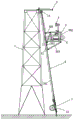
As shown in fig. 1 to 5, a novel transmission line inspection robot line loading and unloading device comprises an iron tower 1, wherein transition guide rails 2 are connected to the iron tower 1, a bearing platform 3 is connected to the lower portions of the transition guide rails 2 through a lifting device, an inspection robot 4 is mounted on the bearing platform 3, and traveling wheels 5 which can be folded or extended are mounted on the inspection robot 4, and the novel transmission line inspection robot is characterized in that the inspection robot 4 can ascend and descend between the ground and the transition guide rails 2 through the lifting device, an arc section 201 which is bent inwards is correspondingly arranged on the transition guide rails 2, a lifting section 202 which is suitable for the traveling wheels 5 of the inspection robot 4 to penetrate is formed between the arc section 201 and the transition guide rails 2 on two sides, and after the traveling wheels 5 ascend and penetrate the lifting section 202, the traveling wheels 5 extend and fall on the transition guide rails 2 on two sides of the arc section 201;
the lifting device comprises a lifting cableway 6 and a winch 7, the bearing platform 3 is respectively connected with the lifting cableway 6 and the winch 7, so that the bearing platform 3 can be lifted up and down along the lifting cableway 6, and the lifting cableway 6 is a flexible cableway.
When in work: when the two walking wheels 5 are lower than the arc-shaped section 201, the two walking wheels 5 are in a furled state, the bearing platform 3 is lifted through the winch 7, the inspection robot 4 is lifted, and meanwhile, the walking wheels 5 in the furled state penetrate through the lifting interval 202, when the walking wheels 5 are higher than the arc-shaped section 201, the two walking wheels 5 are unfolded, the inspection robot 4 descends, the walking wheels 5 fall on the transition guide rails 2 on the two sides of the arc-shaped section 201, and the on-line of the inspection robot 4 is completed; if need roll off the production line, hoist engine 7 drive load-bearing platform 3, will patrol and examine 4 promotions of robot, then walking wheel 5 draws in, descends and falls to ground along the interval 202 of lift equally, accomplishes promptly and rolls off the production line, and whole process is by operating personnel remote control, need not artifical high altitude construction, effectively reduces accident potential safety hazard and improves work efficiency.
In addition, the flexible lifting cableway 6 is convenient to disassemble and assemble and simple in structure, and the problems of complex installation and high difficulty in the prior art are effectively solved.
Preferably, the arc-shaped section 201 is connected with the iron tower 1 through a first bracket 8, the transition guide rails 2 on both sides of the arc-shaped section 201 are connected with the iron tower 1 through a second bracket 9, and the length of the first bracket 8 is smaller than that of the second bracket 9; the length of first bracket 8 is less than the length of second bracket 9, forms segmental arc 201 to constitute and promote interval 202, second bracket 9 is adjustable, makes segmental arc 201 adjustable, thereby makes the area of promoting interval 202 adjustable, adapts to not unidimensional walking wheel.
Preferably, two cableway hangers 10 are mounted on the iron tower 1 on both sides of the first bracket 8, and one ends of the two lifting cableways 6 are connected with the two cableway hangers 10; one end of the convenient and flexible lifting cableway 6 is connected with the iron tower 1.
Preferably, the bearing platform 3 is sleeved on the lifting cableway 6 through an upper guide sleeve and a lower guide sleeve 11, and the bearing platform 3 is lifted up and down along the lifting cableway 6 through the winch 7; the guide sleeve 11 and the flexible hoisting ropeway 6 form a guide connection, so that the bearing platform 3 can be lifted up and down better.
Preferably, the transition guide rail 2 is provided with an arc section 201 bent towards the steering wheel of the iron tower 1; similarly, the arc-shaped section 201 can also be bent outwards, namely, bent opposite to the iron tower 1, and the same effect can be achieved, but the structure bent inwards is more compact and reasonable.
Preferably, the winch 7 is fixed on the ground through a mounting plate 12, and the other end of the lifting cableway 6 is connected with the mounting plate 12; simple and fast installation and high efficiency.
Preferably, the second bracket 9 is adjustably mounted on the iron tower 1 through a fastener 13; adjusting the second bracket 9, the arc of the arc segment 201 can be adjusted.
Preferably, said hoisting runway 6 is a flexible wire rope; the steel cable has firm structure and flexibility, and is convenient and quick to install.
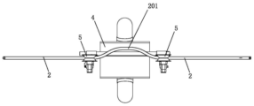
Preferably, the carrying platform 3 comprises a carrying base 301, a carrying plate 302 and two adjusting rods 303, the inspection robot 4 is arranged on the carrying base 301, two guide sleeves 11 are mounted at the upper end and the lower end of the carrying plate 302, the two guide sleeves 11 are movably connected with the upper end and the lower end of the carrying base 301 through the two adjusting rods 303 respectively, and the carrying base 301 between the two adjusting rods 303 is movably connected with the carrying plate 302 through a connecting plate 13; the bearing plate 302 which is arranged in an inclined mode is suitable for the inclination setting of the lifting cableway 6, the guide sleeve 11 is arranged on the bearing plate 302, the inspection robot 4 is borne by the bearing seat 301 and movably connected with the bearing plate 302, the adjustment is convenient, the two adjusting rods 303 can adjust the bearing seat 301 relative to the bearing plate 302, and the adjustment is simple and convenient.
Preferably, the fixed pulley 14 is mounted on the first bracket 8, and the hoist 7 includes a hoist cable 701, and the hoist cable 701 is connected to the fixed pulley 14.
It should be noted that the description of the present invention and the accompanying drawings illustrate preferred embodiments of the present invention, but the present invention may be embodied in many different forms and is not limited to the embodiments described in the present specification, which are provided as additional limitations to the present invention and to provide a more thorough understanding of the present disclosure. Moreover, the above technical features are combined with each other to form various embodiments which are not listed above, and all the embodiments are regarded as the scope of the present invention described in the specification; further, modifications and variations will occur to those skilled in the art in light of the foregoing description, and it is intended to cover all such modifications and variations as fall within the true spirit and scope of the invention as defined by the appended claims.
Claims (10)
1. A novel transmission line inspection robot line loading and unloading device comprises an iron tower, transition guide rails are connected to the iron tower, a bearing platform is connected to the lower portions of the transition guide rails through a lifting device, an inspection robot is mounted on the bearing platform, and traveling wheels capable of being folded or stretched are mounted on the inspection robot; when being less than the segmental arc, two walking wheels are in a furled state, the bearing platform is lifted through the winch, the inspection robot is made to ascend, the walking wheels in the furled state penetrate through a lifting interval, when the walking wheels are higher than the segmental arc, the two walking wheels are unfolded, the inspection robot descends, the walking wheels fall on transition guide rails on two sides of the segmental arc, the lifting device comprises a lifting cableway and a winch, the bearing platform is respectively connected with the lifting cableway and the winch, the bearing platform is made to ascend and descend along the lifting cableway, and the lifting cableway is a flexible cableway.
2. The novel power transmission line inspection robot line loading and unloading device of claim 1, wherein the arc-shaped section is connected with an iron tower through a first bracket, the transition guide rails on two sides of the arc-shaped section are connected with the iron tower through a second bracket, and the length of the first bracket is smaller than that of the second bracket.
3. The novel power transmission line inspection robot line loading and unloading device according to claim 2, wherein the iron towers on two sides of the first bracket are provided with cableway hangers, and one end of the lifting cableway is connected with the cableway hangers.
4. The novel power transmission line inspection robot line loading and unloading device according to claim 1, wherein the bearing platform is sleeved on the lifting cableway through an upper guide sleeve and a lower guide sleeve, and the bearing platform is lifted up and down along the lifting cableway through a winch.
5. The novel power transmission line inspection robot line loading and unloading device according to claim 1, wherein the transition guide rail is provided with an arc section bent towards a steering wheel of an iron tower.
6. The novel power transmission line inspection robot line loading and unloading device according to claim 3, wherein the winch is fixed on the ground through a mounting plate, and the other end of the lifting cableway is connected with the mounting plate.
7. The novel power transmission line inspection robot line loading and unloading device of claim 2, wherein the second bracket is adjustably mounted on the iron tower through a fastener.
8. The novel power transmission line inspection robot line loading and unloading device according to any one of claims 1 to 7, wherein the hoisting ropeway is a flexible steel cable.
9. The novel power transmission line inspection robot line loading and unloading device according to claim 4, wherein the bearing platform comprises a bearing seat, a bearing plate and two adjusting rods, the inspection robot is arranged on the bearing seat, two guide sleeves are mounted at the upper end and the lower end of the bearing plate, the two guide sleeves are movably connected with the upper end and the lower end of the bearing seat through the two adjusting rods respectively, and the bearing seat between the two adjusting rods is movably connected with the bearing plate through a connecting plate.
10. The novel power transmission line inspection robot line loading and unloading device according to claim 2, wherein the first bracket is provided with a fixed pulley, the winch comprises a hoisting cable, and the hoisting cable is connected with the fixed pulley.
Priority Applications (1)
| Application Number | Priority Date | Filing Date | Title |
|---|---|---|---|
| CN201710332641.0A CN107425463B (en) | 2017-05-12 | 2017-05-12 | Novel transmission line patrol robot wire feeding and discharging device |
Applications Claiming Priority (1)
| Application Number | Priority Date | Filing Date | Title |
|---|---|---|---|
| CN201710332641.0A CN107425463B (en) | 2017-05-12 | 2017-05-12 | Novel transmission line patrol robot wire feeding and discharging device |
Publications (2)
| Publication Number | Publication Date |
|---|---|
| CN107425463A CN107425463A (en) | 2017-12-01 |
| CN107425463B true CN107425463B (en) | 2023-04-07 |
Family
ID=60424934
Family Applications (1)
| Application Number | Title | Priority Date | Filing Date |
|---|---|---|---|
| CN201710332641.0A Active CN107425463B (en) | 2017-05-12 | 2017-05-12 | Novel transmission line patrol robot wire feeding and discharging device |
Country Status (1)
| Country | Link |
|---|---|
| CN (1) | CN107425463B (en) |
Families Citing this family (8)
| Publication number | Priority date | Publication date | Assignee | Title |
|---|---|---|---|---|
| CN108649484B (en) * | 2018-05-18 | 2020-03-27 | 云南电网有限责任公司电力科学研究院 | Equipment cabinet assembly suitable for all-terrain maintenance for shared tower |
| CN108458889B (en) * | 2018-06-29 | 2024-02-20 | 洛阳视距智能科技有限公司 | Electric power inspection sensing equipment simulation test platform |
| CN109659859A (en) | 2019-01-28 | 2019-04-19 | 广东科凯达智能机器人有限公司 | Power transmission line intelligent cruising inspection system |
| CN110328676B (en) * | 2019-07-23 | 2022-08-12 | 广州科智电力科技有限公司 | Full-automatic inspection robot for high-voltage line |
| CN110277749B (en) * | 2019-07-23 | 2020-10-23 | 常州海恩德智能电力科技股份有限公司 | High-voltage line inspection robot capable of climbing poles and wires |
| CN111716320A (en) * | 2020-06-01 | 2020-09-29 | 国电南瑞科技股份有限公司 | Automatic line loading and unloading device for inspection robot with flexible track |
| CN112038975A (en) * | 2020-09-10 | 2020-12-04 | 云南电网有限责任公司电力科学研究院 | Overhead working inspection robot wire feeding and discharging system |
| CN114278146B (en) * | 2021-12-28 | 2023-07-04 | 国网天津市电力公司建设分公司 | Robot intelligent tower assembling construction method for high-voltage transmission tower |
Citations (1)
| Publication number | Priority date | Publication date | Assignee | Title |
|---|---|---|---|---|
| CN203932810U (en) * | 2014-05-22 | 2014-11-05 | 郭德江 | Walk on overhead ground wire drive saddle line inspection device and this device across tower guide rail |
Family Cites Families (6)
| Publication number | Priority date | Publication date | Assignee | Title |
|---|---|---|---|---|
| JP3756126B2 (en) * | 2002-04-17 | 2006-03-15 | ファナック株式会社 | Robot striatum guide device |
| CN202943630U (en) * | 2012-12-10 | 2013-05-22 | 中国科学院沈阳自动化研究所 | Composite travelling and holding mechanism of patrol robot |
| CN105048336B (en) * | 2015-06-03 | 2017-03-22 | 武汉大学 | Automatic up-and-down device of line patrol robot of strain tower |
| CN104993422B (en) * | 2015-06-29 | 2017-05-10 | 广东电网有限责任公司电力科学研究院 | Line inspection robot on-line and off-line device and line inspection robot on-line and off-line system provided with same |
| CN106374388B (en) * | 2016-10-21 | 2018-05-29 | 国网山东省电力公司电力科学研究院 | A kind of whole accessible crusing robot system of aerial earth wire and method |
| CN206712337U (en) * | 2017-05-12 | 2017-12-05 | 广东科凯达智能机器人有限公司 | Coil inserting apparatus on new transmission line polling robot |
-
2017
- 2017-05-12 CN CN201710332641.0A patent/CN107425463B/en active Active
Patent Citations (1)
| Publication number | Priority date | Publication date | Assignee | Title |
|---|---|---|---|---|
| CN203932810U (en) * | 2014-05-22 | 2014-11-05 | 郭德江 | Walk on overhead ground wire drive saddle line inspection device and this device across tower guide rail |
Also Published As
| Publication number | Publication date |
|---|---|
| CN107425463A (en) | 2017-12-01 |
Similar Documents
| Publication | Publication Date | Title |
|---|---|---|
| CN107425463B (en) | Novel transmission line patrol robot wire feeding and discharging device | |
| CN105442458B (en) | Method for hanging and installing stay cable of cable-stayed bridge special-shaped tower pillar | |
| CN110510527A (en) | A kind of installation system and its construction method of high slope variable cross-section side slope prefabricated section | |
| CN108179695A (en) | A kind of modular assembly formula is met an urgent need bridge and its erection method | |
| CN202544476U (en) | Tower crane type holding rod | |
| CN205387439U (en) | Mast hoisting accessory | |
| CN104973517A (en) | Electric gantry platform for installing sintering machine head equipment and application method thereof | |
| CN202245865U (en) | Device for hoisting head pulley of sintering machine | |
| CN214935394U (en) | Automatic steel arch rib location hoist of adjusting | |
| JP3150572B2 (en) | Bridge erection equipment | |
| CN105846351A (en) | Line patrol robot mechanical structure and obstacle surmounting method therefor | |
| CN110040638B (en) | Cable-mounted crane device for mounting stiff beam of suspension bridge and mounting method | |
| CN206712337U (en) | Coil inserting apparatus on new transmission line polling robot | |
| CN2868965Y (en) | Automobile crane hoisting device | |
| CN101804944A (en) | Device for exchanging wire rope of gantry crane | |
| CN110654977A (en) | Flexible-straight converter valve submodule replacing tool and method | |
| CN205653070U (en) | Tensile gantry crane can monitor | |
| CN205275061U (en) | Semi -portal crane | |
| CN105200922B (en) | A kind of steel truss girder segment installation on ground transport device and transportation resources | |
| CN208179557U (en) | A kind of arm mechanism of crusing robot | |
| CN104192469A (en) | Electric tower sliding and conveying device and application method thereof | |
| CN106877231B (en) | Support vehicle for rush-repair of power transmission line | |
| CN104876165A (en) | Mobile mounting and maintenance platform of photovoltaic component | |
| CN204859074U (en) | Portable installation and maintenance platform of photovoltaic module | |
| CN205820743U (en) | A kind of power equipment Multifunctional carrying car |
Legal Events
| Date | Code | Title | Description |
|---|---|---|---|
| PB01 | Publication | ||
| PB01 | Publication | ||
| SE01 | Entry into force of request for substantive examination | ||
| CB03 | Change of inventor or designer information |
Inventor after: Li Fang Inventor after: Jia Shaochun Inventor after: Fan Guangmian Inventor after: Wu Jixian Inventor after: Liu Jintao Inventor before: Li Fang Inventor before: Jia Shaochun Inventor before: Fan Guangmian Inventor before: Wu Jixian Inventor before: Liu Miantao |
|
| CB03 | Change of inventor or designer information | ||
| GR01 | Patent grant | ||
| GR01 | Patent grant |