RU2402106C2 - Amorphous oxide and field transistor using it - Google Patents
Amorphous oxide and field transistor using it Download PDFInfo
- Publication number
- RU2402106C2 RU2402106C2 RU2008143340A RU2008143340A RU2402106C2 RU 2402106 C2 RU2402106 C2 RU 2402106C2 RU 2008143340 A RU2008143340 A RU 2008143340A RU 2008143340 A RU2008143340 A RU 2008143340A RU 2402106 C2 RU2402106 C2 RU 2402106C2
- Authority
- RU
- Russia
- Prior art keywords
- film
- amorphous oxide
- amorphous
- concentration
- oxygen
- Prior art date
Links
- 239000000203 mixture Substances 0.000 claims abstract description 80
- 108091006149 Electron carriers Proteins 0.000 claims abstract description 36
- 150000001875 compounds Chemical class 0.000 claims abstract description 28
- 229910052733 gallium Inorganic materials 0.000 claims abstract description 10
- 229910052782 aluminium Inorganic materials 0.000 claims abstract description 7
- 229910052796 boron Inorganic materials 0.000 claims abstract description 7
- 229910052727 yttrium Inorganic materials 0.000 claims abstract description 6
- 229910052760 oxygen Inorganic materials 0.000 claims description 128
- 239000001301 oxygen Substances 0.000 claims description 127
- QVGXLLKOCUKJST-UHFFFAOYSA-N atomic oxygen Chemical compound [O] QVGXLLKOCUKJST-UHFFFAOYSA-N 0.000 claims description 120
- 239000012212 insulator Substances 0.000 claims description 64
- 239000000969 carrier Substances 0.000 claims description 60
- 229910052738 indium Inorganic materials 0.000 claims description 34
- 229910052725 zinc Inorganic materials 0.000 claims description 32
- 229910052718 tin Inorganic materials 0.000 claims description 29
- 230000005669 field effect Effects 0.000 claims description 28
- 239000004065 semiconductor Substances 0.000 abstract description 36
- 230000000694 effects Effects 0.000 abstract description 8
- 239000013078 crystal Substances 0.000 abstract description 4
- 230000005611 electricity Effects 0.000 abstract 1
- 239000000126 substance Substances 0.000 abstract 1
- 239000010408 film Substances 0.000 description 347
- XLOMVQKBTHCTTD-UHFFFAOYSA-N Zinc monoxide Chemical compound [Zn]=O XLOMVQKBTHCTTD-UHFFFAOYSA-N 0.000 description 126
- 239000000758 substrate Substances 0.000 description 108
- 238000000034 method Methods 0.000 description 94
- 239000010409 thin film Substances 0.000 description 79
- 239000011787 zinc oxide Substances 0.000 description 63
- 230000015572 biosynthetic process Effects 0.000 description 59
- 239000011701 zinc Substances 0.000 description 57
- 238000004549 pulsed laser deposition Methods 0.000 description 50
- 229910007541 Zn O Inorganic materials 0.000 description 49
- 239000008186 active pharmaceutical agent Substances 0.000 description 40
- 230000008569 process Effects 0.000 description 38
- 239000012298 atmosphere Substances 0.000 description 36
- 239000011521 glass Substances 0.000 description 34
- 239000012535 impurity Substances 0.000 description 28
- 239000013081 microcrystal Substances 0.000 description 27
- LFQSCWFLJHTTHZ-UHFFFAOYSA-N Ethanol Chemical compound CCO LFQSCWFLJHTTHZ-UHFFFAOYSA-N 0.000 description 22
- 229910018072 Al 2 O 3 Inorganic materials 0.000 description 16
- 230000007547 defect Effects 0.000 description 16
- 125000004429 atom Chemical group 0.000 description 15
- 239000000463 material Substances 0.000 description 15
- PCHJSUWPFVWCPO-UHFFFAOYSA-N gold Chemical compound [Au] PCHJSUWPFVWCPO-UHFFFAOYSA-N 0.000 description 14
- 229910052737 gold Inorganic materials 0.000 description 14
- 239000010931 gold Substances 0.000 description 14
- 238000001459 lithography Methods 0.000 description 14
- 238000000206 photolithography Methods 0.000 description 14
- 229920000139 polyethylene terephthalate Polymers 0.000 description 14
- 239000005020 polyethylene terephthalate Substances 0.000 description 14
- 230000007423 decrease Effects 0.000 description 13
- 238000009826 distribution Methods 0.000 description 13
- 239000007789 gas Substances 0.000 description 13
- 238000004519 manufacturing process Methods 0.000 description 13
- 229910052757 nitrogen Inorganic materials 0.000 description 13
- CSCPPACGZOOCGX-UHFFFAOYSA-N Acetone Chemical compound CC(C)=O CSCPPACGZOOCGX-UHFFFAOYSA-N 0.000 description 12
- 239000000654 additive Substances 0.000 description 12
- 239000011734 sodium Substances 0.000 description 12
- 239000010936 titanium Substances 0.000 description 12
- IJGRMHOSHXDMSA-UHFFFAOYSA-N Atomic nitrogen Chemical compound N#N IJGRMHOSHXDMSA-UHFFFAOYSA-N 0.000 description 11
- 238000000151 deposition Methods 0.000 description 11
- 238000004544 sputter deposition Methods 0.000 description 11
- XKRFYHLGVUSROY-UHFFFAOYSA-N Argon Chemical compound [Ar] XKRFYHLGVUSROY-UHFFFAOYSA-N 0.000 description 10
- 229920002799 BoPET Polymers 0.000 description 10
- 230000001276 controlling effect Effects 0.000 description 10
- 230000000996 additive effect Effects 0.000 description 9
- 150000002500 ions Chemical class 0.000 description 9
- 239000002985 plastic film Substances 0.000 description 9
- 229910052708 sodium Inorganic materials 0.000 description 9
- 239000000243 solution Substances 0.000 description 9
- 229910052720 vanadium Inorganic materials 0.000 description 9
- 229910052726 zirconium Inorganic materials 0.000 description 9
- 229910020923 Sn-O Inorganic materials 0.000 description 8
- 238000004458 analytical method Methods 0.000 description 8
- 229910052799 carbon Inorganic materials 0.000 description 8
- 238000010586 diagram Methods 0.000 description 8
- 238000011156 evaluation Methods 0.000 description 8
- 229910052751 metal Inorganic materials 0.000 description 8
- 239000002184 metal Substances 0.000 description 8
- 229910052698 phosphorus Inorganic materials 0.000 description 8
- 239000004033 plastic Substances 0.000 description 8
- 229920003023 plastic Polymers 0.000 description 8
- 229920006255 plastic film Polymers 0.000 description 8
- 229910052719 titanium Inorganic materials 0.000 description 8
- 229910052793 cadmium Inorganic materials 0.000 description 7
- 230000008859 change Effects 0.000 description 7
- 239000003153 chemical reaction reagent Substances 0.000 description 7
- 229910052802 copper Inorganic materials 0.000 description 7
- 238000005566 electron beam evaporation Methods 0.000 description 7
- 229910052731 fluorine Inorganic materials 0.000 description 7
- 229910052744 lithium Inorganic materials 0.000 description 7
- 229910052748 manganese Inorganic materials 0.000 description 7
- 229910052759 nickel Inorganic materials 0.000 description 7
- 229910052763 palladium Inorganic materials 0.000 description 7
- -1 polyethylene terephthalate Polymers 0.000 description 7
- 238000002601 radiography Methods 0.000 description 7
- 238000000235 small-angle X-ray scattering Methods 0.000 description 7
- 238000005507 spraying Methods 0.000 description 7
- 229910019092 Mg-O Inorganic materials 0.000 description 6
- 229910019395 Mg—O Inorganic materials 0.000 description 6
- 238000005238 degreasing Methods 0.000 description 6
- 230000008021 deposition Effects 0.000 description 6
- 238000009837 dry grinding Methods 0.000 description 6
- 239000012071 phase Substances 0.000 description 6
- 229920006395 saturated elastomer Polymers 0.000 description 6
- 229910052710 silicon Inorganic materials 0.000 description 6
- 238000005245 sintering Methods 0.000 description 6
- 229910021642 ultra pure water Inorganic materials 0.000 description 6
- 239000012498 ultrapure water Substances 0.000 description 6
- 229910005191 Ga 2 O 3 Inorganic materials 0.000 description 5
- 229910004298 SiO 2 Inorganic materials 0.000 description 5
- 229910052786 argon Inorganic materials 0.000 description 5
- 238000002156 mixing Methods 0.000 description 5
- 239000002904 solvent Substances 0.000 description 5
- 238000002604 ultrasonography Methods 0.000 description 5
- 229910006404 SnO 2 Inorganic materials 0.000 description 4
- 229910021645 metal ion Inorganic materials 0.000 description 4
- 230000010355 oscillation Effects 0.000 description 4
- 238000012545 processing Methods 0.000 description 4
- XUIMIQQOPSSXEZ-UHFFFAOYSA-N Silicon Chemical compound [Si] XUIMIQQOPSSXEZ-UHFFFAOYSA-N 0.000 description 3
- 229910021417 amorphous silicon Inorganic materials 0.000 description 3
- 239000000919 ceramic Substances 0.000 description 3
- 230000003247 decreasing effect Effects 0.000 description 3
- 230000006735 deficit Effects 0.000 description 3
- 238000005137 deposition process Methods 0.000 description 3
- 238000013461 design Methods 0.000 description 3
- 238000005401 electroluminescence Methods 0.000 description 3
- 238000010438 heat treatment Methods 0.000 description 3
- 238000005259 measurement Methods 0.000 description 3
- 230000007246 mechanism Effects 0.000 description 3
- 239000010703 silicon Substances 0.000 description 3
- 239000007858 starting material Substances 0.000 description 3
- 230000003746 surface roughness Effects 0.000 description 3
- 238000004876 x-ray fluorescence Methods 0.000 description 3
- 230000005355 Hall effect Effects 0.000 description 2
- 206010021143 Hypoxia Diseases 0.000 description 2
- 229910052765 Lutetium Inorganic materials 0.000 description 2
- 238000002441 X-ray diffraction Methods 0.000 description 2
- 239000000370 acceptor Substances 0.000 description 2
- 238000013459 approach Methods 0.000 description 2
- 239000012300 argon atmosphere Substances 0.000 description 2
- 230000005540 biological transmission Effects 0.000 description 2
- 239000002772 conduction electron Substances 0.000 description 2
- 239000000470 constituent Substances 0.000 description 2
- 230000001419 dependent effect Effects 0.000 description 2
- 229910052732 germanium Inorganic materials 0.000 description 2
- 229910052736 halogen Inorganic materials 0.000 description 2
- 125000005843 halogen group Chemical group 0.000 description 2
- 150000002367 halogens Chemical class 0.000 description 2
- 150000002739 metals Chemical class 0.000 description 2
- 230000005012 migration Effects 0.000 description 2
- 238000013508 migration Methods 0.000 description 2
- 229910052758 niobium Inorganic materials 0.000 description 2
- 230000003287 optical effect Effects 0.000 description 2
- 238000002360 preparation method Methods 0.000 description 2
- 230000001105 regulatory effect Effects 0.000 description 2
- 230000000087 stabilizing effect Effects 0.000 description 2
- 229910052715 tantalum Inorganic materials 0.000 description 2
- 238000007740 vapor deposition Methods 0.000 description 2
- 239000012808 vapor phase Substances 0.000 description 2
- XLYOFNOQVPJJNP-UHFFFAOYSA-N water Chemical compound O XLYOFNOQVPJJNP-UHFFFAOYSA-N 0.000 description 2
- DGAQECJNVWCQMB-PUAWFVPOSA-M Ilexoside XXIX Chemical compound C[C@@H]1CC[C@@]2(CC[C@@]3(C(=CC[C@H]4[C@]3(CC[C@@H]5[C@@]4(CC[C@@H](C5(C)C)OS(=O)(=O)[O-])C)C)[C@@H]2[C@]1(C)O)C)C(=O)O[C@H]6[C@@H]([C@H]([C@@H]([C@H](O6)CO)O)O)O.[Na+] DGAQECJNVWCQMB-PUAWFVPOSA-M 0.000 description 1
- 229910052774 Proactinium Inorganic materials 0.000 description 1
- 238000000862 absorption spectrum Methods 0.000 description 1
- 239000007864 aqueous solution Substances 0.000 description 1
- 230000008901 benefit Effects 0.000 description 1
- 238000001354 calcination Methods 0.000 description 1
- 238000001816 cooling Methods 0.000 description 1
- 230000006378 damage Effects 0.000 description 1
- 238000009792 diffusion process Methods 0.000 description 1
- 229910001873 dinitrogen Inorganic materials 0.000 description 1
- 238000010894 electron beam technology Methods 0.000 description 1
- 238000013213 extrapolation Methods 0.000 description 1
- 229920002457 flexible plastic Polymers 0.000 description 1
- 229920005570 flexible polymer Polymers 0.000 description 1
- 239000008187 granular material Substances 0.000 description 1
- 238000002347 injection Methods 0.000 description 1
- 239000007924 injection Substances 0.000 description 1
- 230000001678 irradiating effect Effects 0.000 description 1
- 230000031700 light absorption Effects 0.000 description 1
- 239000004973 liquid crystal related substance Substances 0.000 description 1
- 238000001819 mass spectrum Methods 0.000 description 1
- 239000011159 matrix material Substances 0.000 description 1
- 230000035699 permeability Effects 0.000 description 1
- 229910021420 polycrystalline silicon Inorganic materials 0.000 description 1
- 229920000307 polymer substrate Polymers 0.000 description 1
- 238000002128 reflection high energy electron diffraction Methods 0.000 description 1
- 238000004611 spectroscopical analysis Methods 0.000 description 1
- 238000001228 spectrum Methods 0.000 description 1
- 239000007921 spray Substances 0.000 description 1
- 239000013077 target material Substances 0.000 description 1
- 238000007725 thermal activation Methods 0.000 description 1
- YONPGGFAJWQGJC-UHFFFAOYSA-K titanium(iii) chloride Chemical compound Cl[Ti](Cl)Cl YONPGGFAJWQGJC-UHFFFAOYSA-K 0.000 description 1
- 229910052721 tungsten Inorganic materials 0.000 description 1
- 238000009281 ultraviolet germicidal irradiation Methods 0.000 description 1
- 238000001771 vacuum deposition Methods 0.000 description 1
Images


Classifications
-
- H—ELECTRICITY
- H01—ELECTRIC ELEMENTS
- H01L—SEMICONDUCTOR DEVICES NOT COVERED BY CLASS H10
- H01L29/00—Semiconductor devices specially adapted for rectifying, amplifying, oscillating or switching and having potential barriers; Capacitors or resistors having potential barriers, e.g. a PN-junction depletion layer or carrier concentration layer; Details of semiconductor bodies or of electrodes thereof ; Multistep manufacturing processes therefor
- H01L29/02—Semiconductor bodies ; Multistep manufacturing processes therefor
- H01L29/12—Semiconductor bodies ; Multistep manufacturing processes therefor characterised by the materials of which they are formed
- H01L29/26—Semiconductor bodies ; Multistep manufacturing processes therefor characterised by the materials of which they are formed including, apart from doping materials or other impurities, elements provided for in two or more of the groups H01L29/16, H01L29/18, H01L29/20, H01L29/22, H01L29/24, e.g. alloys
-
- H—ELECTRICITY
- H01—ELECTRIC ELEMENTS
- H01L—SEMICONDUCTOR DEVICES NOT COVERED BY CLASS H10
- H01L21/00—Processes or apparatus adapted for the manufacture or treatment of semiconductor or solid state devices or of parts thereof
- H01L21/02—Manufacture or treatment of semiconductor devices or of parts thereof
- H01L21/02104—Forming layers
- H01L21/02365—Forming inorganic semiconducting materials on a substrate
- H01L21/02367—Substrates
- H01L21/0237—Materials
- H01L21/02422—Non-crystalline insulating materials, e.g. glass, polymers
-
- H—ELECTRICITY
- H01—ELECTRIC ELEMENTS
- H01L—SEMICONDUCTOR DEVICES NOT COVERED BY CLASS H10
- H01L21/00—Processes or apparatus adapted for the manufacture or treatment of semiconductor or solid state devices or of parts thereof
- H01L21/02—Manufacture or treatment of semiconductor devices or of parts thereof
- H01L21/02104—Forming layers
- H01L21/02365—Forming inorganic semiconducting materials on a substrate
- H01L21/02518—Deposited layers
- H01L21/02521—Materials
- H01L21/02551—Group 12/16 materials
- H01L21/02554—Oxides
-
- H—ELECTRICITY
- H01—ELECTRIC ELEMENTS
- H01L—SEMICONDUCTOR DEVICES NOT COVERED BY CLASS H10
- H01L21/00—Processes or apparatus adapted for the manufacture or treatment of semiconductor or solid state devices or of parts thereof
- H01L21/02—Manufacture or treatment of semiconductor devices or of parts thereof
- H01L21/02104—Forming layers
- H01L21/02365—Forming inorganic semiconducting materials on a substrate
- H01L21/02518—Deposited layers
- H01L21/02521—Materials
- H01L21/02565—Oxide semiconducting materials not being Group 12/16 materials, e.g. ternary compounds
-
- H—ELECTRICITY
- H01—ELECTRIC ELEMENTS
- H01L—SEMICONDUCTOR DEVICES NOT COVERED BY CLASS H10
- H01L21/00—Processes or apparatus adapted for the manufacture or treatment of semiconductor or solid state devices or of parts thereof
- H01L21/02—Manufacture or treatment of semiconductor devices or of parts thereof
- H01L21/02104—Forming layers
- H01L21/02365—Forming inorganic semiconducting materials on a substrate
- H01L21/02518—Deposited layers
- H01L21/02587—Structure
- H01L21/0259—Microstructure
- H01L21/02592—Microstructure amorphous
-
- H—ELECTRICITY
- H01—ELECTRIC ELEMENTS
- H01L—SEMICONDUCTOR DEVICES NOT COVERED BY CLASS H10
- H01L21/00—Processes or apparatus adapted for the manufacture or treatment of semiconductor or solid state devices or of parts thereof
- H01L21/02—Manufacture or treatment of semiconductor devices or of parts thereof
- H01L21/02104—Forming layers
- H01L21/02365—Forming inorganic semiconducting materials on a substrate
- H01L21/02612—Formation types
- H01L21/02617—Deposition types
- H01L21/02631—Physical deposition at reduced pressure, e.g. MBE, sputtering, evaporation
-
- H—ELECTRICITY
- H01—ELECTRIC ELEMENTS
- H01L—SEMICONDUCTOR DEVICES NOT COVERED BY CLASS H10
- H01L21/00—Processes or apparatus adapted for the manufacture or treatment of semiconductor or solid state devices or of parts thereof
- H01L21/02—Manufacture or treatment of semiconductor devices or of parts thereof
- H01L21/04—Manufacture or treatment of semiconductor devices or of parts thereof the devices having potential barriers, e.g. a PN junction, depletion layer or carrier concentration layer
- H01L21/34—Manufacture or treatment of semiconductor devices or of parts thereof the devices having potential barriers, e.g. a PN junction, depletion layer or carrier concentration layer the devices having semiconductor bodies not provided for in groups H01L21/0405, H01L21/0445, H01L21/06, H01L21/16 and H01L21/18 with or without impurities, e.g. doping materials
- H01L21/42—Bombardment with radiation
- H01L21/423—Bombardment with radiation with high-energy radiation
- H01L21/428—Bombardment with radiation with high-energy radiation using electromagnetic radiation, e.g. laser radiation
-
- H—ELECTRICITY
- H01—ELECTRIC ELEMENTS
- H01L—SEMICONDUCTOR DEVICES NOT COVERED BY CLASS H10
- H01L27/00—Devices consisting of a plurality of semiconductor or other solid-state components formed in or on a common substrate
- H01L27/02—Devices consisting of a plurality of semiconductor or other solid-state components formed in or on a common substrate including semiconductor components specially adapted for rectifying, oscillating, amplifying or switching and having potential barriers; including integrated passive circuit elements having potential barriers
- H01L27/12—Devices consisting of a plurality of semiconductor or other solid-state components formed in or on a common substrate including semiconductor components specially adapted for rectifying, oscillating, amplifying or switching and having potential barriers; including integrated passive circuit elements having potential barriers the substrate being other than a semiconductor body, e.g. an insulating body
- H01L27/1214—Devices consisting of a plurality of semiconductor or other solid-state components formed in or on a common substrate including semiconductor components specially adapted for rectifying, oscillating, amplifying or switching and having potential barriers; including integrated passive circuit elements having potential barriers the substrate being other than a semiconductor body, e.g. an insulating body comprising a plurality of TFTs formed on a non-semiconducting substrate, e.g. driving circuits for AMLCDs
- H01L27/1222—Devices consisting of a plurality of semiconductor or other solid-state components formed in or on a common substrate including semiconductor components specially adapted for rectifying, oscillating, amplifying or switching and having potential barriers; including integrated passive circuit elements having potential barriers the substrate being other than a semiconductor body, e.g. an insulating body comprising a plurality of TFTs formed on a non-semiconducting substrate, e.g. driving circuits for AMLCDs with a particular composition, shape or crystalline structure of the active layer
- H01L27/1225—Devices consisting of a plurality of semiconductor or other solid-state components formed in or on a common substrate including semiconductor components specially adapted for rectifying, oscillating, amplifying or switching and having potential barriers; including integrated passive circuit elements having potential barriers the substrate being other than a semiconductor body, e.g. an insulating body comprising a plurality of TFTs formed on a non-semiconducting substrate, e.g. driving circuits for AMLCDs with a particular composition, shape or crystalline structure of the active layer with semiconductor materials not belonging to the group IV of the periodic table, e.g. InGaZnO
-
- H—ELECTRICITY
- H01—ELECTRIC ELEMENTS
- H01L—SEMICONDUCTOR DEVICES NOT COVERED BY CLASS H10
- H01L27/00—Devices consisting of a plurality of semiconductor or other solid-state components formed in or on a common substrate
- H01L27/02—Devices consisting of a plurality of semiconductor or other solid-state components formed in or on a common substrate including semiconductor components specially adapted for rectifying, oscillating, amplifying or switching and having potential barriers; including integrated passive circuit elements having potential barriers
- H01L27/12—Devices consisting of a plurality of semiconductor or other solid-state components formed in or on a common substrate including semiconductor components specially adapted for rectifying, oscillating, amplifying or switching and having potential barriers; including integrated passive circuit elements having potential barriers the substrate being other than a semiconductor body, e.g. an insulating body
- H01L27/1214—Devices consisting of a plurality of semiconductor or other solid-state components formed in or on a common substrate including semiconductor components specially adapted for rectifying, oscillating, amplifying or switching and having potential barriers; including integrated passive circuit elements having potential barriers the substrate being other than a semiconductor body, e.g. an insulating body comprising a plurality of TFTs formed on a non-semiconducting substrate, e.g. driving circuits for AMLCDs
- H01L27/124—Devices consisting of a plurality of semiconductor or other solid-state components formed in or on a common substrate including semiconductor components specially adapted for rectifying, oscillating, amplifying or switching and having potential barriers; including integrated passive circuit elements having potential barriers the substrate being other than a semiconductor body, e.g. an insulating body comprising a plurality of TFTs formed on a non-semiconducting substrate, e.g. driving circuits for AMLCDs with a particular composition, shape or layout of the wiring layers specially adapted to the circuit arrangement, e.g. scanning lines in LCD pixel circuits
-
- H—ELECTRICITY
- H01—ELECTRIC ELEMENTS
- H01L—SEMICONDUCTOR DEVICES NOT COVERED BY CLASS H10
- H01L29/00—Semiconductor devices specially adapted for rectifying, amplifying, oscillating or switching and having potential barriers; Capacitors or resistors having potential barriers, e.g. a PN-junction depletion layer or carrier concentration layer; Details of semiconductor bodies or of electrodes thereof ; Multistep manufacturing processes therefor
- H01L29/02—Semiconductor bodies ; Multistep manufacturing processes therefor
- H01L29/06—Semiconductor bodies ; Multistep manufacturing processes therefor characterised by their shape; characterised by the shapes, relative sizes, or dispositions of the semiconductor regions ; characterised by the concentration or distribution of impurities within semiconductor regions
-
- H—ELECTRICITY
- H01—ELECTRIC ELEMENTS
- H01L—SEMICONDUCTOR DEVICES NOT COVERED BY CLASS H10
- H01L29/00—Semiconductor devices specially adapted for rectifying, amplifying, oscillating or switching and having potential barriers; Capacitors or resistors having potential barriers, e.g. a PN-junction depletion layer or carrier concentration layer; Details of semiconductor bodies or of electrodes thereof ; Multistep manufacturing processes therefor
- H01L29/66—Types of semiconductor device ; Multistep manufacturing processes therefor
- H01L29/66007—Multistep manufacturing processes
- H01L29/66969—Multistep manufacturing processes of devices having semiconductor bodies not comprising group 14 or group 13/15 materials
-
- H—ELECTRICITY
- H01—ELECTRIC ELEMENTS
- H01L—SEMICONDUCTOR DEVICES NOT COVERED BY CLASS H10
- H01L29/00—Semiconductor devices specially adapted for rectifying, amplifying, oscillating or switching and having potential barriers; Capacitors or resistors having potential barriers, e.g. a PN-junction depletion layer or carrier concentration layer; Details of semiconductor bodies or of electrodes thereof ; Multistep manufacturing processes therefor
- H01L29/66—Types of semiconductor device ; Multistep manufacturing processes therefor
- H01L29/68—Types of semiconductor device ; Multistep manufacturing processes therefor controllable by only the electric current supplied, or only the electric potential applied, to an electrode which does not carry the current to be rectified, amplified or switched
- H01L29/76—Unipolar devices, e.g. field effect transistors
- H01L29/772—Field effect transistors
- H01L29/78—Field effect transistors with field effect produced by an insulated gate
- H01L29/786—Thin film transistors, i.e. transistors with a channel being at least partly a thin film
- H01L29/7869—Thin film transistors, i.e. transistors with a channel being at least partly a thin film having a semiconductor body comprising an oxide semiconductor material, e.g. zinc oxide, copper aluminium oxide, cadmium stannate
- H01L29/78693—Thin film transistors, i.e. transistors with a channel being at least partly a thin film having a semiconductor body comprising an oxide semiconductor material, e.g. zinc oxide, copper aluminium oxide, cadmium stannate the semiconducting oxide being amorphous
-
- H—ELECTRICITY
- H01—ELECTRIC ELEMENTS
- H01L—SEMICONDUCTOR DEVICES NOT COVERED BY CLASS H10
- H01L29/00—Semiconductor devices specially adapted for rectifying, amplifying, oscillating or switching and having potential barriers; Capacitors or resistors having potential barriers, e.g. a PN-junction depletion layer or carrier concentration layer; Details of semiconductor bodies or of electrodes thereof ; Multistep manufacturing processes therefor
- H01L29/66—Types of semiconductor device ; Multistep manufacturing processes therefor
- H01L29/68—Types of semiconductor device ; Multistep manufacturing processes therefor controllable by only the electric current supplied, or only the electric potential applied, to an electrode which does not carry the current to be rectified, amplified or switched
- H01L29/76—Unipolar devices, e.g. field effect transistors
- H01L29/772—Field effect transistors
- H01L29/78—Field effect transistors with field effect produced by an insulated gate
- H01L29/786—Thin film transistors, i.e. transistors with a channel being at least partly a thin film
- H01L29/78696—Thin film transistors, i.e. transistors with a channel being at least partly a thin film characterised by the structure of the channel, e.g. multichannel, transverse or longitudinal shape, length or width, doping structure, or the overlap or alignment between the channel and the gate, the source or the drain, or the contacting structure of the channel
Landscapes
- Engineering & Computer Science (AREA)
- Power Engineering (AREA)
- Microelectronics & Electronic Packaging (AREA)
- Physics & Mathematics (AREA)
- Condensed Matter Physics & Semiconductors (AREA)
- General Physics & Mathematics (AREA)
- Computer Hardware Design (AREA)
- Manufacturing & Machinery (AREA)
- Ceramic Engineering (AREA)
- Chemical & Material Sciences (AREA)
- Crystallography & Structural Chemistry (AREA)
- Electromagnetism (AREA)
- Optics & Photonics (AREA)
- Health & Medical Sciences (AREA)
- Toxicology (AREA)
- Materials Engineering (AREA)
- Thin Film Transistor (AREA)
- Liquid Crystal (AREA)
- Physical Deposition Of Substances That Are Components Of Semiconductor Devices (AREA)
- Dram (AREA)
- Physical Vapour Deposition (AREA)
Abstract
Description
ОБЛАСТЬ ТЕХНИКИ, К КОТОРОЙ ОТНОСИТСЯ ИЗОБРЕТЕНИЕFIELD OF THE INVENTION
Настоящее изобретение относится к аморфному оксиду. Настоящее изобретение также относится к полевому транзистору, выполненному с использованием указанного аморфного оксида.The present invention relates to an amorphous oxide. The present invention also relates to a field effect transistor made using said amorphous oxide.
УРОВЕНЬ ТЕХНИКИBACKGROUND
В последние годы плоскопанельный дисплей (ППД) получил широкое распространение в результате технологического прогресса в области жидких кристаллов и электролюминесценции (EL). ППД приводится в действие посредством схемы активной матрицы, состоящей из тонкопленочного полевого транзистора (ТПТ), использующего в качестве активного слоя тонкую аморфную кремниевую пленку или тонкую пленку из поликристаллического кремния, расположенную на стеклянной подложке.In recent years, a flat panel display (PDD) has become widespread as a result of technological progress in the field of liquid crystals and electroluminescence (EL). The PPD is driven by an active matrix circuit consisting of a thin film field effect transistor (TFT) using a thin amorphous silicon film or a thin polycrystalline silicon film located on a glass substrate as the active layer.
С другой стороны, была сделана попытка вместо стеклянной подложки использовать легкую и гибкую полимерную подложку, чтобы еще больше уменьшить толщину ППД, сделать его более тонким и стойким к разрушению. Однако поскольку для производства транзистора с использованием вышеописанной тонкой кремниевой пленки требуется термический процесс со сравнительно высокой температурой, трудно сформировать тонкую кремниевую пленку непосредственно на полимерной подложке с низкой термостойкостью.On the other hand, an attempt was made instead of a glass substrate to use a light and flexible polymer substrate to further reduce the thickness of the PPD, to make it thinner and more resistant to destruction. However, since a transistor using the above-described thin silicon film requires a thermal process with a relatively high temperature, it is difficult to form a thin silicon film directly on a polymer substrate with low heat resistance.
В связи с этим активно разрабатывался (выложенная заявка на патент Японии № 2003-298062) ТПТ, использующий тонкую полупроводниковую оксидную пленку, содержащую в основном, например, ZnO, который может быть сформирован в виде пленки при низкой температуре.In this regard, TPT is being actively developed (Japanese Patent Application Laid-open No. 2003-298062) using a thin semiconductor oxide film containing mainly, for example, ZnO, which can be formed into a film at low temperature.
Однако ТПТ, использующий обычные тонкие пленки оксидных полупроводников, не обеспечивает производительность на том уровне, который характерен для ТПТ, использующего кремний.However, TPT using conventional thin films of oxide semiconductors does not provide performance at the level that is typical for TPT using silicon.
Настоящее изобретение относится к аморфному оксиду, а также к полевому транзистору, использующему аморфный оксид.The present invention relates to amorphous oxide, as well as to a field effect transistor using amorphous oxide.
РАСКРЫТИЕ ИЗОБРЕТЕНИЯSUMMARY OF THE INVENTION
Целью настоящего изобретения является предоставление аморфного оксида, который функционирует как подходящий полупроводник, для использования в активном слое полупроводникового устройства, например тонкопленочного транзистора, а также предоставление полевого транзистора.The aim of the present invention is the provision of amorphous oxide, which functions as a suitable semiconductor, for use in the active layer of a semiconductor device, such as a thin film transistor, as well as the provision of a field effect transistor.
Согласно аспекту настоящего изобретения предоставляется аморфный оксид, содержащий микрокристаллы и имеющий концентрацию электронных носителей менее 1018/см3. Аморфный оксид предпочтительно содержит, по меньшей мере, один элемент, выбранный из группы, состоящей из In, Zn и Sn.According to an aspect of the present invention, there is provided an amorphous oxide comprising microcrystals and having an electron carrier concentration of less than 10 18 / cm 3 . The amorphous oxide preferably contains at least one element selected from the group consisting of In, Zn and Sn.
В качестве альтернативы аморфный оксид предпочтительно представляет собой любой оксид, выбранный из группы, состоящей из оксида, содержащего In, Zn и Sn; оксида, содержащего In и Zn; оксида, содержащего In и Sn; и оксида, содержащего In.Alternatively, the amorphous oxide is preferably any oxide selected from the group consisting of an oxide containing In, Zn and Sn; an oxide containing In and Zn; an oxide containing In and Sn; and oxide containing In.
В качестве альтернативы аморфный оксид предпочтительно представляет собой оксид, содержащий In, Zn и Sn.Alternatively, the amorphous oxide is preferably an oxide containing In, Zn and Sn.
Согласно другому аспекту настоящего изобретения предоставляется аморфный оксид, в котором подвижность электронов увеличивается с увеличением концентрации электронных носителей.According to another aspect of the present invention, an amorphous oxide is provided in which electron mobility increases with increasing concentration of electron carriers.
Согласно другому варианту осуществления настоящего изобретения предоставляется полевой транзистор, содержащий активный слой, сформированный из аморфного оксида, содержащий микрокристаллы и электрод затвора, сформированный таким образом, чтобы он был обращен к активному слою через изолятор затвора.According to another embodiment of the present invention, there is provided a field effect transistor comprising an active layer formed of amorphous oxide containing microcrystals and a gate electrode formed so that it faces the active layer through the gate insulator.
Транзистор предпочтительно представляет собой транзистор нормально выключенного типа.The transistor is preferably a normally off type transistor.
Согласно другому варианту осуществления настоящего изобретения предоставляется аморфный оксид, состав которого изменяется с толщиной слоя и который имеет концентрацию электронных носителей менее 1018/см3.According to another embodiment of the present invention, an amorphous oxide is provided, the composition of which varies with the layer thickness and which has an electron carrier concentration of less than 10 18 / cm 3 .
Аморфный оксид предпочтительно содержит, по меньшей мере, один элемент, выбранный из группы, состоящей из In, Zn и Sn.The amorphous oxide preferably contains at least one element selected from the group consisting of In, Zn and Sn.
В качестве альтернативы аморфный оксид предпочтительно выбирают из группы, состоящей из оксида, содержащего In, Zn и Sn; оксида, содержащего In и Zn; оксида, содержащего In и Sn; и оксида, содержащего In.Alternatively, the amorphous oxide is preferably selected from the group consisting of an oxide containing In, Zn and Sn; an oxide containing In and Zn; an oxide containing In and Sn; and oxide containing In.
В качестве альтернативы аморфный оксид предпочтительно представляет собой оксид, содержащий In, Zn и Sn.Alternatively, the amorphous oxide is preferably an oxide containing In, Zn and Sn.
Согласно другому аспекту настоящего изобретения предоставляется полевой транзистор, содержащийAccording to another aspect of the present invention, there is provided a field effect transistor comprising
активный слой из аморфного оксида, состав которого изменяется с толщиной слоя иactive layer of amorphous oxide, the composition of which varies with the thickness of the layer and
электрод затвора, сформированный таким образом, чтобы он был обращен к активному слою через изолятор затвора,a gate electrode formed so that it faces the active layer through a gate insulator,
причем активный слой содержит первую область и вторую область, которая расположена ближе к изолятору затвора, чем первая область, и концентрация кислорода в первой области выше, чем концентрация кислорода во второй области.moreover, the active layer contains a first region and a second region, which is located closer to the gate insulator than the first region, and the oxygen concentration in the first region is higher than the oxygen concentration in the second region.
Согласно другому аспекту настоящего изобретения предоставляется полевой транзистор, содержащийAccording to another aspect of the present invention, there is provided a field effect transistor comprising
активный слой из аморфного оксида, имеющий, по меньшей мере, один элемент, выбранный из группы, состоящей из In, Zn и Sn, иan amorphous oxide active layer having at least one element selected from the group consisting of In, Zn and Sn, and
электрод затвора, сформированный таким образом, чтобы он был обращен к активному слою через изолятор затвора,a gate electrode formed so that it faces the active layer through a gate insulator,
причем активный слой содержит первую область и вторую область, которая расположена к изолятору затвора ближе первой области, и концентрация In во второй области выше, чем концентрация кислорода в первой области, или концентрация Zn во второй области выше, чем концентрация кислорода в первой области.moreover, the active layer contains a first region and a second region, which is closer to the gate insulator to the gate insulator, and the In concentration in the second region is higher than the oxygen concentration in the first region, or the Zn concentration in the second region is higher than the oxygen concentration in the first region.
Согласно другому варианту осуществления настоящего изобретения предоставляется аморфный оксид, состав которого изменяется в направлении толщины слоя,According to another embodiment of the present invention, an amorphous oxide is provided, the composition of which varies in the direction of the layer thickness,
причем подвижность электронов увеличивается с увеличением концентрации электронных носителей.moreover, the electron mobility increases with increasing concentration of electronic carriers.
Согласно другому аспекту настоящего изобретения предоставляется полевой транзистор, содержащийAccording to another aspect of the present invention, there is provided a field effect transistor comprising
активный слой из аморфного оксида, имеющего, по меньшей мере, один элемент, выбранный из группы, состоящей из In и Zn, иan active layer of amorphous oxide having at least one element selected from the group consisting of In and Zn, and
электрод затвора, сформированный таким образом, чтобы он был обращен к активному слою через изолятор затвора,a gate electrode formed so that it faces the active layer through a gate insulator,
причем активный слой содержит первую область и вторую область, которая расположена ближе к изолятору затвора, чем первая область, и концентрация In во второй области выше, чем концентрация In в первой области, или концентрация Zn во второй области выше, чем концентрация Zn в первой области.moreover, the active layer contains a first region and a second region, which is closer to the gate insulator than the first region, and the concentration of In in the second region is higher than the concentration of In in the first region, or the concentration of Zn in the second region is higher than the concentration of Zn in the first region .
Согласно другому варианту осуществления настоящего изобретения предоставляется аморфный оксид, содержащий один тип элемента или множество типов элементов, выбранных из группы, состоящей из Li, Na, Mn, Ni, Pd, Cu, Cd, C, N, P, Ti, Zr, V, Ru, Ge, Sn и F, и имеющий концентрацию электронных носителей менее 1018/см3.According to another embodiment of the present invention, there is provided an amorphous oxide comprising one type of element or a plurality of types of elements selected from the group consisting of Li, Na, Mn, Ni, Pd, Cu, Cd, C, N, P, Ti, Zr, V , Ru, Ge, Sn, and F, and having an electron carrier concentration of less than 10 18 / cm 3 .
Аморфный оксид предпочтительно содержит, по меньшей мере, один элемент, выбранный из группы, состоящей из In, Zn и Sn.The amorphous oxide preferably contains at least one element selected from the group consisting of In, Zn and Sn.
В качестве альтернативы аморфный оксид предпочтительно выбирают из группы, состоящей из оксида, содержащего In, Zn и Sn; оксида, содержащего In и Zn; оксида, содержащего In и Sn; оксида, содержащего In.Alternatively, the amorphous oxide is preferably selected from the group consisting of an oxide containing In, Zn and Sn; an oxide containing In and Zn; an oxide containing In and Sn; oxide containing In.
В качестве альтернативы аморфный оксид предпочтительно содержит In, Zn и Ga.Alternatively, the amorphous oxide preferably contains In, Zn and Ga.
Согласно другому аспекту настоящего изобретения предоставляется аморфный оксид, содержащий, по меньшей мере, один элемент, выбранный из группы, состоящей из Li, Na, Mn, Ni, Pd, Cu, Cd, C, N, P, Ti, Zr, V, Ru, Ge, Sn и F, причем подвижность электронов увеличивается с увеличением концентрации электронных носителей.According to another aspect of the present invention, there is provided an amorphous oxide comprising at least one element selected from the group consisting of Li, Na, Mn, Ni, Pd, Cu, Cd, C, N, P, Ti, Zr, V, Ru, Ge, Sn and F, and the electron mobility increases with increasing concentration of electronic carriers.
Согласно другому аспекту настоящего изобретения предоставляется полевой транзистор, содержащийAccording to another aspect of the present invention, there is provided a field effect transistor comprising
активный слой из аморфного оксида, содержащего, по меньшей мере, один элемент, выбранный из группы, состоящей из Li, Na, Mn, Ni, Pd, Cu, Cd, C, N, P, Ti, Zr, V, Ru, Ge, Sn и F, иactive layer of amorphous oxide containing at least one element selected from the group consisting of Li, Na, Mn, Ni, Pd, Cu, Cd, C, N, P, Ti, Zr, V, Ru, Ge , Sn and F, and
электрод затвора, сформированный таким образом, чтобы он был обращен к активному слою через изолятор затвора.a gate electrode formed so that it faces the active layer through the gate insulator.
Более того, в настоящем изобретении аморфный оксид предпочтительно выбирают из группы, состоящей из оксида, содержащего In, Zn и Sn; оксида, содержащего In и Zn; оксида, содержащего In и Sn; оксида, содержащего In.Moreover, in the present invention, the amorphous oxide is preferably selected from the group consisting of an oxide containing In, Zn and Sn; an oxide containing In and Zn; an oxide containing In and Sn; oxide containing In.
В результате исследований оксидных полупроводников авторами настоящего изобретения было обнаружено, что вышеуказанный ZnO формируется в виде поликристаллической фазы, вызывающей рассеяние носителей на поверхности между поликристаллическими гранулами с более низкой электронной подвижностью. Более того, было обнаружено, что в ZnO образуется большое количество кислородных дефектов, что приводит к появлению большого количества электронов и усложняет уменьшение электропроводности. Таким образом, даже если к транзистору не приложено напряжение затвора, между терминалом истока и терминалом стока возникает сильный электрический ток, который не позволяет получить нормально выключенное состояние ТПТ и увеличивает отношение транзистора включено/выключено.As a result of studies of oxide semiconductors, the authors of the present invention found that the above ZnO is formed as a polycrystalline phase, causing the scattering of carriers on the surface between polycrystalline granules with lower electron mobility. Moreover, it was found that a large number of oxygen defects are formed in ZnO, which leads to the appearance of a large number of electrons and complicates the decrease in electrical conductivity. Thus, even if the gate voltage is not applied to the transistor, a strong electric current arises between the source terminal and the drain terminal, which does not allow to obtain a normally turned-off state of the TFT and increases the ratio of the transistor on / off.
Авторы настоящего изобретения исследовали пленку из аморфного оксида ZnxMyInzO(x+3y/2+3z/2) (где М представляет собой, по меньшей мере, один из Al или Ga), описанную в выложенной заявке на патент Японии №2000-044236. Материал имеет концентрацию электронных носителей не менее 1×10¹⁸/см3 и подходит для использования в качестве прозрачного электрода. Однако оксид с концентрацией электронных носителей не менее 1×10¹⁸/см3, используемый в канальном слое ТПТ, не может обеспечить достаточное отношение включено/выключено и не подходит для ТПТ нормально выключенного типа. Таким образом, обычная пленка из аморфного оксида не обеспечивает концентрацию электронных носителей, меньшую чем 1×10¹⁸/см3.The inventors of the present invention examined a film of amorphous oxide Zn x M y In z O (x + 3y / 2 + 3z / 2) (where M represents at least one of Al or Ga) described in Japanese Patent Application Laid-Open No. 2000-044236. The material has an electron carrier concentration of at least 1 × 10 18 / cm 3 and is suitable for use as a transparent electrode. However, an oxide with an electron carrier concentration of at least 1 × 10 18 / cm 3 used in the channel layer of a solid-state filter cannot provide a sufficient on / off ratio and is not suitable for a normally-switched type solid-state filter. Thus, a conventional amorphous oxide film does not provide an electron carrier concentration of less than 1 × 10 18 / cm 3 .
Авторы настоящего изобретения изготовили ТПТ, используя в качестве активного слоя полевого транзистора аморфный оксид с концентрацией электронных носителей менее 1×10¹⁸/см3. Было обнаружено, что ТПТ имеет желаемые характеристики и может быть использован в плоскопанельном дисплее, таком как светоизлучающее устройство.The inventors of the present invention fabricated TPT using an amorphous oxide with an electron carrier concentration of less than 1 × 10 18 / cm 3 as the active layer of the field effect transistor. It was found that the TFT has the desired characteristics and can be used in a flat panel display, such as a light emitting device.
Более того, авторы настоящего изобретения исследовали материал InGaO3(ZnO)m и условия формирования пленки из этого материала и обнаружили, что путем управления параметрами кислородсодержащей атмосферы во время формирования пленки можно довести концентрацию носителей в этом материале до уровня менее 1×10¹⁸/см3.Moreover, the authors of the present invention examined the InGaO 3 (ZnO) m material and the film forming conditions from this material and found that by controlling the parameters of the oxygen-containing atmosphere during film formation, it is possible to bring the carrier concentration in this material to less than 1 × 10 18 / cm 3 .
Приведенные выше пояснения даны с точки зрения использования аморфного оксида в качестве активного слоя, который функционирует, например, в качестве канального слоя ТПТ. Однако настоящее изобретение не ограничивается случаем, в котором используется такой активный слой.The above explanations are given from the point of view of using amorphous oxide as an active layer that functions, for example, as a channel layer of TPT. However, the present invention is not limited to the case in which such an active layer is used.
Вышеприведенное описание в основном дано для случая, в котором аморфный оксид используется в качестве активного слоя, функционирующего в качестве канального слоя ТПТ. Однако настоящее изобретение не ограничивается таким случаем.The above description is mainly given for the case in which an amorphous oxide is used as an active layer functioning as a channel layer of TPT. However, the present invention is not limited to such a case.
Согласно настоящему изобретению предоставляется аморфный оксид, который подходит для использования в канальном слое транзистора, например ТПТ. Настоящее изобретение также предоставляет полевой транзистор, имеющий хорошие рабочие характеристики.According to the present invention, an amorphous oxide is provided which is suitable for use in a channel layer of a transistor, for example a TFT. The present invention also provides a field effect transistor having good performance.
КРАТКОЕ ОПИСАНИЕ ЧЕРТЕЖЕЙBRIEF DESCRIPTION OF THE DRAWINGS
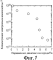
Фиг.1 представляет собой диаграмму, показывающую связь между концентрацией электронных носителей в аморфной пленке на основе In-Ga-Zn-O, сформированной способом импульсного лазерного осаждения, и парциальным давлением кислорода во время формирования пленки;Figure 1 is a diagram showing the relationship between the concentration of electronic carriers in an In-Ga-Zn-O-based amorphous film formed by the pulsed laser deposition method and the oxygen partial pressure during film formation;
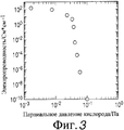
Фиг.2 представляет собой диаграмму, показывающую связь между электропроводностью аморфной пленки на основе In-Ga-Zn-O, сформированной способом напыления в атмосфере аргона, и парциальным давлением кислорода во время формирования пленки;Figure 2 is a diagram showing the relationship between the electrical conductivity of an In-Ga-Zn-O-based amorphous film formed by the sputtering method in an argon atmosphere and the oxygen partial pressure during film formation;
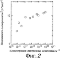
Фиг.3 представляет собой диаграмму, показывающую связь между количеством электронных носителей и подвижностью электронов в аморфной пленке на основе In-Ga-Zn-O, сформированной способом импульсного лазерного осаждения;Figure 3 is a diagram showing the relationship between the number of electronic carriers and electron mobility in an In-Ga-Zn-O based amorphous film formed by pulsed laser deposition;
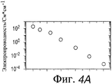
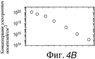
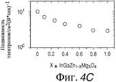
Фиг.4А, 4В и 4С представляют собой диаграммы, показывающие изменение электропроводности, концентрации носителей и подвижности электронов в зависимости от значения х в пленке InGaO3(Zn1-xMgxO), сформированной способом импульсного лазерного осаждения в атмосфере при парциальном давлении кислорода, равном 0,8 Па;4A, 4B and 4C are diagrams showing changes in electrical conductivity, carrier concentration and electron mobility as a function of x in an InGaO 3 film (Zn 1-x Mg x O) formed by pulsed laser deposition in the atmosphere at an oxygen partial pressure equal to 0.8 Pa;
Фиг.5 представляет собой блок-схему, показывающую структуру МДП-транзистора с верхним затвором;5 is a block diagram showing the structure of an MOS transistor with an upper gate;
Фиг.6 представляет собой диаграмму, показывающую вольт-амперную характеристику МДП-транзистора с верхним затвором;6 is a diagram showing a current-voltage characteristic of a top-gate MOS transistor;
Фиг.7 представляет собой блок-схему, показывающую устройство для импульсного лазерного осаждения;7 is a block diagram showing an apparatus for pulsed laser deposition;
Фиг.8 представляет собой блок-схему, показывающую устройство для формирования пленки напылением.8 is a block diagram showing an apparatus for forming a spray film.
НАИЛУЧШИЕ РЕЖИМЫ ОСУЩЕСТВЛЕНИЯ НАСТОЯЩЕГО ИЗОБРЕТЕНИЯBEST MODES FOR CARRYING OUT THE PRESENT INVENTION
Ниже описаны 1-3 варианты осуществления изобретения. Затем описан материал аморфного оксида, применяемый в настоящем изобретении. В описанных ниже вариантах осуществления оксид на основе In-Ga-Zn-O, как правило, описывается в вариантах осуществления; однако настоящее изобретение не ограничено таким материалом.1-3 embodiments of the invention are described below. The amorphous oxide material used in the present invention is then described. In the embodiments described below, an In-Ga-Zn-O-based oxide is typically described in embodiments; however, the present invention is not limited to such material.
Первый вариант осуществления: аморфный оксид, имеющий микрокристаллыFirst Embodiment: Amorphous Oxide Having Microcrystals
Первый вариант осуществления изобретения относится к аморфному оксиду, отличающемуся тем, что он содержит микрокристалл (микрокристаллы). Содержится или нет микрокристалл (микрокристаллы) в аморфном оксиде, определяют, используя ТЕМ (трансмиссионную электронную микроскопическую) фотографию участка, сформированного пленкой из аморфного оксида. Пленка из аморфного оксида согласно настоящему изобретению содержит In-Ga-Zn-O, и состав пленки из аморфного оксида в кристаллическом состоянии представлен в виде InGaO3(ZnO)m (m представляет собой натуральное число меньше 6).The first embodiment of the invention relates to an amorphous oxide, characterized in that it contains a microcrystal (microcrystals). Whether or not microcrystals (microcrystals) are contained in the amorphous oxide is determined using a TEM (transmission electron microscopic) photograph of the portion formed by the amorphous oxide film. The amorphous oxide film of the present invention contains In-Ga-Zn-O, and the composition of the crystalline amorphous oxide film is presented as InGaO 3 (ZnO) m (m is a natural number less than 6).
Оксиды, обозначенные в описании термином “аморфный оксид”, имеют концентрацию электронных носителей менее 1018/см3 или проявляют тенденцию, при которой с увеличением подвижности электронов увеличивается концентрация электронных носителей. В зависимости от типа использования ТПТ предпочтительным является изготовление ТПТ нормально выключенного типа.The oxides referred to in the description by the term “amorphous oxide” have an electron carrier concentration of less than 10 18 / cm 3 or show a tendency in which the concentration of electron carriers increases with increasing electron mobility. Depending on the type of use of the TPT, it is preferable to manufacture a TPT of a normally off type.
В качестве альтернативы пленка из аморфного оксида согласно настоящему изобретению содержит In-Ga-Zn-Mg-O, и состав пленки из аморфного оксида в кристаллическом состоянии представлен в виде InGaO3(Zn1-xMgxO)m (m представляет собой натуральное число меньше 6, 0<x≤1). Предпочтительным является то, что такие пленки из аморфного оксида имеют подвижность электронов выше 1 см2/В·сек.Alternatively, the amorphous oxide film of the present invention contains In-Ga-Zn-Mg-O, and the composition of the crystalline amorphous oxide film is presented as InGaO 3 (Zn 1-x Mg x O) m (m is natural the number is less than 6, 0 <x≤1). It is preferable that such amorphous oxide films have electron mobility greater than 1 cm 2 / V · sec.
Авторы настоящего изобретения обнаружили, что использование такой упомянутой выше пленки в качестве канального слоя создает возможность для формирования гибкого ТПТ со следующими рабочими характеристиками: ток затвора менее 0,1 микроампер в выключенном ТПТ (нормально выключен), отношение включено/выключено превышает 1×10³ и является проницаемым для видимого света.The authors of the present invention found that the use of such a film as the channel layer makes it possible to form a flexible TFT with the following performance characteristics: the gate current is less than 0.1 microamps with the TFT turned off (normally off), the on / off ratio exceeds 1 × 10 3 and is permeable to visible light.
Такая прозрачная пленка характеризуется тем, что подвижность электронов увеличивается с увеличением количества проводящих электронов. В качестве подложки для формирования прозрачной пленки можно использовать стеклянную подложку, пластмассовую подложку и пластмассовую пленку.Such a transparent film is characterized in that the electron mobility increases with an increase in the number of conducting electrons. As the substrate for forming a transparent film, a glass substrate, a plastic substrate, and a plastic film can be used.
При использовании в качестве канального слоя транзистора прозрачной оксидной пленки предпочтительным является использование в качестве изолятора затвора одного типа соединения, выбранного из группы, состоящей из Al2O3, Y2O3 и HfO2, или смешанного кристаллического соединения, содержащего, по меньшей мере, два типа соединений, выбранных из группы, состоящей из Al2O3, Y2O3 и HfO2.When using a transparent oxide film as the channel layer of the transistor, it is preferable to use as a gate insulator one type of compound selected from the group consisting of Al 2 O 3 , Y 2 O 3 and HfO 2 , or a mixed crystalline compound containing at least , two types of compounds selected from the group consisting of Al 2 O 3 , Y 2 O 3 and HfO 2 .
С целью усиления электрической сопротивляемости предпочтительным является формирование пленки (прозрачной оксидной пленки) в содержащей кислород атмосфере при облучении света без добавления посторонних ионов.In order to enhance electrical resistance, it is preferable to form a film (transparent oxide film) in an oxygen-containing atmosphere by irradiating light without adding foreign ions.
Состав пленкиFilm composition
В прозрачной тонкой пленке из аморфного оксида, которая имеет состав в кристаллическом состоянии, представленный в виде InGaO3(ZnO)m (m представляет собой натуральное число меньше 6), аморфное состояние сохраняется до температуры 800°С или выше, если m меньше 6. Однако поскольку m увеличивается, другими словами, отношение ZnO к InGaO3 увеличивается (то есть состав пленки приближается к ZnO), пленка кристаллизуется легче.In a transparent thin film of amorphous oxide, which has a composition in the crystalline state, presented as InGaO 3 (ZnO) m (m is a natural number less than 6), the amorphous state persists to a temperature of 800 ° C or higher if m is less than 6. However, since m increases, in other words, the ratio of ZnO to InGaO 3 increases (that is, the composition of the film approaches ZnO), the film crystallizes more easily.
По этой причине предпочтительным является, чтобы значение m было меньше 6 при использовании аморфной пленки в качестве канального слоя аморфного ТПТ. Однако было обнаружено, что при формировании пленки при облучении светом микрокристаллы могут формироваться даже при небольших значениях m.For this reason, it is preferable that the value of m is less than 6 when using an amorphous film as a channel layer of an amorphous TPT. However, it was found that during film formation during irradiation with light, microcrystals can form even at small values of m.
Пленка может быть сформирована способом формирования пленки из паровой фазы с поликристаллическим спеченным корпусом, имеющим состав InGaO3(ZnO)m, который используется в качестве мишени. Для способа формирования пленки из паровой фазы являются подходящими способ напыления и способ импульсного лазерного осаждения. Более того, способ напыления более предпочтителен с точки зрения массового производства.The film can be formed by the method of forming a film from the vapor phase with a polycrystalline sintered body having the composition InGaO 3 (ZnO) m , which is used as a target. For the method of forming a film from the vapor phase, a spraying method and a pulsed laser deposition method are suitable. Moreover, the spraying method is more preferable from the point of view of mass production.
Однако при формировании такой аморфной пленки в обычных условиях в основном образуются кислородные дефекты. Следовательно, концентрация электронных носителей не может быть уменьшена ниже 1×10¹⁸/см3, другими словами, 10 См/см или меньше в терминах электропроводности. При использовании такой обычной тонкой пленки не может быть сформирован транзистор нормально выключенного типа. Однако если прозрачная пленка из аморфного оксида, имеющая состав In-Ga-Zn-O, причем состав в кристаллическом состоянии представлен в виде InGaO3(ZnO)m (m представляет собой натуральное число меньше 6), формируется способом импульсного лазерного осаждения при помощи устройства, показанного на Фиг.7, в атмосфере, имеющей парциальное давление кислорода выше 3,2 Па, концентрация электронных носителей может быть уменьшена ниже чем 1×10¹⁸/см3. В этом случае подложку специально не нагревают и, следовательно, поддерживают приблизительно комнатную температуру. Если в качестве подложки используется пластмассовая пленка, температура пластмассовой пленки предпочтительно поддерживается ниже 100°С.However, during the formation of such an amorphous film under ordinary conditions, oxygen defects are mainly formed. Therefore, the concentration of electronic carriers cannot be reduced below 1 × 10 18 / cm 3 , in other words, 10 S / cm or less in terms of electrical conductivity. When using such a conventional thin film, a normally off type transistor cannot be formed. However, if the transparent amorphous oxide film having the composition In-Ga-Zn-O, and the composition in the crystalline state is represented as InGaO 3 (ZnO) m (m is a natural number less than 6), is formed by pulsed laser deposition using a device shown in Fig.7, in an atmosphere having a partial oxygen pressure above 3.2 Pa, the concentration of electronic carriers can be reduced lower than 1 × 10 18 / cm 3 . In this case, the substrate is not specifically heated and, therefore, approximately room temperature is maintained. If a plastic film is used as the substrate, the temperature of the plastic film is preferably kept below 100 ° C.
Согласно варианту осуществления изобретения аморфный оксид содержит In-Ga-Zn-O и формируется при помощи способа импульсного лазерного осаждения при облучении светом. Более конкретно, изобретение относится к прозрачной тонкой пленке из аморфного оксида, содержащей микрокристалл (микрокристаллы), представленный составом в кристаллическом состоянии в виде InGaO3(ZnO)m (m представляет собой натуральное число меньше 6). С использованием такой пленки может быть сформирован транзистор нормально выключенного типа.According to an embodiment of the invention, the amorphous oxide contains In-Ga-Zn-O and is formed using a pulsed laser deposition method when irradiated with light. More specifically, the invention relates to a transparent thin film of amorphous oxide containing a microcrystal (microcrystals) represented by the composition in a crystalline state in the form of InGaO 3 (ZnO) m (m is a natural number less than 6). Using such a film, a normally off type transistor can be formed.
В такой тонкой пленке можно получить подвижность электронов, превышающую 1 см2/В·сек, и высокое отношение включено/выключено, превышающее 1×10³.In such a thin film, it is possible to obtain electron mobility in excess of 1 cm 2 / V · sec and a high on / off ratio in excess of 1 × 10 3 .
Более того, настоящее изобретение относится к аморфному оксиду, содержащему In-Ga-Zn-O и сформированному способом напыления с использованием газообразного аргона при облучении светом. Более конкретно, настоящее изобретение относится к прозрачной тонкой пленке из аморфного оксида, содержащей микрокристалл (микрокристаллы), представленный составом в кристаллическом состоянии в виде InGaO3(ZnO)m (m представляет собой натуральное число меньше 6). Такая пленка может быть получена способом напыления при помощи устройства, показанного на Фиг.8, в атмосфере с парциальным давлением кислорода выше 1×10⁻² Па. В этом случае температуру подложки специально не увеличивают и, таким образом, поддерживают приблизительно комнатную температуру. Если в качестве подложки используется пластмассовая пленка, температура подложки предпочтительно поддерживается ниже 100°С. Количество электронных носителей может быть уменьшено путем увеличения парциального давления кислорода.Moreover, the present invention relates to an amorphous oxide containing In-Ga-Zn-O and formed by a sputtering method using gaseous argon when irradiated with light. More specifically, the present invention relates to a transparent thin film of amorphous oxide containing a microcrystal (microcrystals) represented by the composition in a crystalline state in the form of InGaO 3 (ZnO) m (m is a natural number less than 6). Such a film can be obtained by sputtering using the device shown in Fig. 8 in an atmosphere with a partial oxygen pressure above 1 × 10 -2 Pa. In this case, the temperature of the substrate is not specifically increased, and thus approximately room temperature is maintained. If a plastic film is used as the substrate, the temperature of the substrate is preferably kept below 100 ° C. The number of electronic carriers can be reduced by increasing the partial pressure of oxygen.
Более конкретно, настоящее изобретение относится к аморфному оксиду, содержащему In-Ga-Zn-O и сформированному способом напыления при облучении светом. Согласно настоящему изобретению транзистор нормально выключенного типа, имеющий отношение включено/выключено, превышающее 1×10³, может быть сформирован при помощи прозрачной тонкой пленки из аморфного оксида, содержащей микрокристалл (микрокристаллы), представленный составом в кристаллическом состоянии в виде InGaO3(ZnO)m (m представляет собой натуральное число меньше 6).More specifically, the present invention relates to an amorphous oxide containing In-Ga-Zn-O and formed by a sputtering method when exposed to light. According to the present invention, a normally off type transistor having an on / off ratio greater than 1 × 10 3 can be formed using a transparent thin film of amorphous oxide containing a microcrystal (microcrystals) represented by the composition in the crystalline state as InGaO 3 (ZnO) m (m is a natural number less than 6).
В тонкой пленке, изготовленной при помощи способа импульсного лазерного осаждения и способом напыления при облучении светом, подвижность электронов увеличивается с увеличением количества проводящих электронов.In a thin film made using a pulsed laser deposition method and a sputtering method when irradiated with light, the electron mobility increases with an increase in the number of conductive electrons.
В этом случае, если в качестве мишени используется поликристалл InGaO3(Zn1-xMgxO)m (m представляет собой натуральное число меньше 6, 0<x≤1), может быть получена аморфная пленка с высокой устойчивостью, имеющая состав InGaO3(Zn1-xMgxO)m даже при парциальном давлении кислорода меньше 1 Па.In this case, if an InGaO 3 polycrystal (Zn 1-x Mg x O) m (m is a natural number less than 6, 0 <x≤1) is used as a target, an amorphous film with high stability having the composition InGaO can be obtained 3 (Zn 1-x Mg x O) m even at a partial oxygen pressure of less than 1 Pa.
Как описано выше, можно избежать образования кислородных дефектов, регулируя парциальное давление кислорода. В результате концентрация электронных носителей может быть уменьшена без добавления заданных посторонних ионов. Аморфный оксид согласно настоящему изобретению может быть получен путем формирования тонкой пленки согласно любой одной из Фиг.1-5 при облучении светом. Если используется устройство по Фиг.7 или 8, пленка может быть сформирована при парциальном давлении кислорода, например, в заданной области, как описано ниже. В аморфном состоянии, содержащем микрокристалл (микрокристаллы) граница раздела зерен микрокристалла покрыта (окружена) аморфной структурой. Следовательно, фактически не существует границы раздела зерен, способной захватывать подвижные электроны и дырки в отличие от поликристаллического состояния, подобного оксиду цинка. В результате может быть получена тонкая аморфная пленка, имеющая высокую подвижность электронов. Более того, количество проводящих электронов может быть уменьшено без добавления заданных посторонних ионов. Поскольку электроны не рассеиваются ионами примеси, может сохраняться высокая подвижность электронов. Микрокристаллы согласно настоящему изобретению не ограничены микрокристаллами, имеющими состав, представленный в виде InGaO3(ZnO)m (m представляет собой натуральное число меньше 6).As described above, the formation of oxygen defects can be avoided by adjusting the partial pressure of oxygen. As a result, the concentration of electronic carriers can be reduced without adding specified foreign ions. The amorphous oxide according to the present invention can be obtained by forming a thin film according to any one of FIGS. 1-5 when irradiated with light. If the device of FIGS. 7 or 8 is used, a film can be formed at a partial oxygen pressure, for example, in a predetermined region, as described below. In an amorphous state containing a microcrystal (microcrystals), the grain boundary of the microcrystal is covered (surrounded) by an amorphous structure. Therefore, in fact, there is no grain interface capable of capturing mobile electrons and holes, in contrast to the polycrystalline state, similar to zinc oxide. As a result, a thin amorphous film having a high electron mobility can be obtained. Moreover, the number of conducting electrons can be reduced without adding predetermined extraneous ions. Since electrons are not scattered by impurity ions, high electron mobility may persist. The microcrystals according to the present invention are not limited to microcrystals having a composition represented as InGaO 3 (ZnO) m (m is a natural number less than 6).
В транзисторе с тонкой пленкой, использующем вышеуказанную прозрачную пленку, изолятор затвора предпочтительно формируют из смешанного кристаллического соединения, содержащего, по меньшей мере, два соединения, выбранных из группы, состоящей из Al2O3, Y2O3 и HfO2. Если дефект (дефицит) имеется на границе между затвором, изолирующим тонкую пленку и тонкую пленку канального слоя, то подвижность электронов уменьшается и имеет место гистерезис как характеристика транзистора. Более того, если тип изолятора затвора отличается, ток утечки сильно изменяется. По этой причине необходимо выбрать подходящий изолятор затвора для канального слоя. Если используется Al2O3 пленка (в качестве изолятора затвора), ток утечки может быть уменьшен. Если используется Y2O3 пленка (в качестве изолятора затвора), может быть уменьшен гистерезис. Если используется HfO2 пленка, имеющая высокую диэлектрическую постоянную, может быть увеличена подвижность электронов. Более того, если используется смешанный кристалл из этих соединений (в качестве изолятора затвора), можно сформировать ТПТ, имеющий небольшой ток утечки и гистерезис и большую подвижность электронов. Поскольку процесс формирования изолятора затвора и процесс формирования канального слоя могут выполняться при комнатной температуре, может быть сформирован не только ТПТ с шахматной структурой, а также ТПТ с обратной шахматной структурой.In a thin film transistor using the above transparent film, the gate insulator is preferably formed from a mixed crystalline compound containing at least two compounds selected from the group consisting of Al 2 O 3 , Y 2 O 3 and HfO 2 . If a defect (deficit) exists at the boundary between the gate that insulates the thin film and the thin film of the channel layer, then the electron mobility decreases and hysteresis occurs as a characteristic of the transistor. Moreover, if the type of gate insulator is different, the leakage current varies greatly. For this reason, you must select a suitable gate insulator for the channel layer. If an Al 2 O 3 film is used (as a gate insulator), the leakage current can be reduced. If a Y 2 O 3 film is used (as a gate insulator), hysteresis can be reduced. If an HfO 2 film having a high dielectric constant is used, the electron mobility can be increased. Moreover, if a mixed crystal of these compounds is used (as a gate insulator), it is possible to form a TFT having a small leakage current and hysteresis and a high electron mobility. Since the process of forming the gate insulator and the process of forming the channel layer can be carried out at room temperature, not only a TFT with a checkerboard structure, but also a TFT with a reverse checkerboard structure can be formed.
ТПТ представляет собой устройство, имеющее три терминала, а именно терминал затвора, терминал истока и терминал стока. Полупроводниковая тонкая пленка, сформированная на изолирующей подложке, такой как керамическое стекло, или пластмассовая подложка используются в ТПТ в качестве канального слоя для миграции электронов и дырок через этот слой. Ток, текущий через канальный слой, управляется путем приложения напряжения к терминалу затвора, тем самым переключая ток между терминалом истока и терминалом стока. Поскольку ТПТ имеет такую функцию переключения, он является активным устройством. Необходимо отметить, что микрокристаллы, содержащиеся в аморфном оксиде, могут быть сформированы путем облучения светом (а именно, облучением света, используя галогенную лампу или УФ-облучение), как упоминалось выше, и могут быть сформированы другими способами помимо облучения светом.A TFT is a device having three terminals, namely a gate terminal, a source terminal, and a drain terminal. A semiconductor thin film formed on an insulating substrate, such as ceramic glass, or a plastic substrate is used in the TPT as a channel layer for the migration of electrons and holes through this layer. The current flowing through the channel layer is controlled by applying voltage to the gate terminal, thereby switching the current between the source terminal and the drain terminal. Since the TFT has such a switching function, it is an active device. It should be noted that microcrystals contained in amorphous oxide can be formed by irradiation with light (namely, irradiation of light using a halogen lamp or UV irradiation), as mentioned above, and can be formed by other methods besides irradiation with light.
Второй вариант осуществления: композиционное распределение аморфного оксидаSecond Embodiment: Compositional Distribution of Amorphous Oxide
Согласно этому варианту осуществления аморфный оксид характеризуется составом, изменяющимся в направлении толщины.According to this embodiment, the amorphous oxide is characterized by a composition that varies in the thickness direction.
Фраза “состав, изменяющийся в направлении толщины” означает, что количество кислорода, содержащегося в оксиде, изменяется в направлении толщины пленки, и элементы, составляющие оксид, изменяются в середине (то есть изменяется состав), и изменяется содержание элементов, составляющих оксид.The phrase “composition changing in the thickness direction” means that the amount of oxygen contained in the oxide changes in the direction of the film thickness, and the elements making up the oxide change in the middle (that is, the composition changes), and the content of the elements making up the oxide changes.
Следовательно, если аморфный оксид используется в качестве активного слоя (также называемого канальным слоем) полевого транзистора, например, является предпочтительным следующее строение. В транзисторе, имеющем активный слой, содержащем аморфный оксид и изолятор затвора, которые находятся в контакте друг с другом на границе раздела, слой аморфного оксида устроен таким образом, что концентрация кислорода около границы раздела выше, чем в области, удаленной от границы раздела. В этом случае, поскольку электрическое сопротивление слоя аморфного оксида, расположенного ближе к границе раздела, выше, то так называемый канал транзистора формируется внутри слоя аморфного оксида, удаленного от границы раздела. Такое строение является предпочтительным, когда граница раздела представляет собой неровную поверхность, поскольку может быть уменьшена утечка тока.Therefore, if amorphous oxide is used as an active layer (also called a channel layer) of a field effect transistor, for example, the following structure is preferred. In a transistor having an active layer containing amorphous oxide and a gate insulator that are in contact with each other at the interface, the amorphous oxide layer is arranged so that the oxygen concentration near the interface is higher than in the region remote from the interface. In this case, since the electrical resistance of the amorphous oxide layer located closer to the interface is higher, the so-called transistor channel is formed inside the amorphous oxide layer remote from the interface. Such a structure is preferred when the interface is an uneven surface, since current leakage can be reduced.
То есть в случае использования вышеуказанного аморфного оксида в качестве активного слоя транзистора является предпочтительным разработать активный слой таким образом, чтобы он содержал первую область и вторую область, расположенную к изолятору затвора ближе первой области, причем концентрация кислорода во второй области превышала концентрацию кислорода в первой области. В этой связи нет необходимости в том, чтобы обе области различались на своих границах, но соответствующие их составы могут меняться постепенно или ступенчато.That is, in the case of using the above amorphous oxide as the active layer of the transistor, it is preferable to design the active layer so that it contains a first region and a second region located closer to the gate region to the gate insulator, the oxygen concentration in the second region exceeding the oxygen concentration in the first region . In this regard, it is not necessary that both regions differ on their borders, but their respective compositions can change gradually or stepwise.
В частности, концентрация электронных носителей аморфного оксида предпочтительно меньше 1018/см3.In particular, the concentration of electronic carriers of amorphous oxide is preferably less than 10 18 / cm 3 .
Направление пленки, сформированное на подложке, означает любое направление, которое не является направлением на плоскости подложки, т.е. направлением, перпендикулярным направлению плоскости подложки. Более того, в транзисторе, имеющем активный слой, сформированный аморфным оксидом, имеющим, по меньшей мере, один элемент, выбранный из группы, состоящей из In и Zn, и изолятор затвора, находящийся в контакте с активным слоем на границе раздела, концентрация In и Zn, содержащаяся в области слоя аморфного оксида (активного слоя), расположенной близко к границе раздела, выше, чем их концентрация в области, расположенной дальше от границы раздела. В этом случае может быть увеличена дрейфовая подвижность электронов.The direction of the film formed on the substrate means any direction that is not a direction on the plane of the substrate, i.e. direction perpendicular to the direction of the plane of the substrate. Moreover, in a transistor having an active layer formed by an amorphous oxide having at least one element selected from the group consisting of In and Zn, and a gate insulator in contact with the active layer at the interface, the concentration of In and Zn contained in the region of the amorphous oxide layer (active layer) located close to the interface is higher than their concentration in the region located further from the interface. In this case, the electron drift mobility can be increased.
То есть в случае использования вышеуказанного аморфного оксида в качестве активного слоя транзистора предпочтительной является разработка активного слоя таким образом, чтобы он содержал первую область и вторую область, которая расположена к изолятору затвора ближе первой области, причем концентрация In и Zn во второй области выше их концентрации в первой области.That is, in the case of using the above amorphous oxide as the active layer of the transistor, it is preferable to design the active layer so that it contains the first region and the second region, which is closer to the gate insulator closer to the first region, and the concentration of In and Zn in the second region is higher than their concentration in the first area.
Согласно второму варианту осуществления изобретения оксидная пленка содержит In-Ga-Zn-O, и ее состав изменяется в направлении толщины пленки, и отличается тем, что состав части, имеющей кристаллическое состояние, представлен в виде InGaO3(ZnO)m (m представляет собой натуральное число меньше 6), и концентрация электронных носителей ниже 1×10¹⁸/см3.According to a second embodiment of the invention, the oxide film contains In-Ga-Zn-O, and its composition changes in the direction of the film thickness, and characterized in that the composition of the part having a crystalline state is represented as InGaO 3 (ZnO) m (m is the natural number is less than 6), and the concentration of electronic carriers is lower than 1 × 10 18 / cm 3 .
В качестве альтернативы оксидная пленка согласно второму варианту осуществления изобретения представляет собой прозрачную пленку из аморфного оксида, содержащую In-Ga-Zn-Mg-O и отличающуюся тем, что состав изменяется в направлении толщины пленки, и состав части, находящейся в кристаллическом состоянии, представлен в виде InGaO3(Zn1-xMgxO)m (m представляет собой натуральное число меньше 6, 0<x≤1), и концентрация электронных носителей ниже 1×10¹⁸/см3. Необходимо отметить, что также является предпочтительным, чтобы эти пленки имели подвижность электронов выше 1 см2/В·сек.Alternatively, the oxide film according to the second embodiment of the invention is a transparent amorphous oxide film containing In-Ga-Zn-Mg-O and characterized in that the composition changes in the direction of the film thickness, and the composition of the crystalline portion is represented in the form of InGaO 3 (Zn 1-x Mg x O) m (m is a natural number less than 6, 0 <x≤1), and the concentration of electronic carriers is below 1 × 10 18 / cm 3 . It should be noted that it is also preferable that these films have an electron mobility above 1 cm 2 / V · sec.
Если вышеуказанная пленка используется в качестве канального слоя, предпочтительным является получение гибкого ТПТ, имеющего следующие характеристики транзистора: ток затвора меньше 0,1 микроампера при выключенном ТПТ (нормально выключенном), отношение включено/выключено выше 1×10⁴, проницаемость для видимого света.If the above film is used as a channel layer, it is preferable to obtain a flexible TFT with the following transistor characteristics: the gate current is less than 0.1 microamperes with the TFT turned off (normally off), the on / off ratio is higher than 1 × 10 4 , and the permeability to visible light.
Необходимо отметить, что такая прозрачная пленка отличается тем, что подвижность электронов увеличивается с увеличением количества проводящих электронов. В качестве подложки для формирования прозрачной пленки может использоваться стеклянная подложка, пластмассовая подложка или пластмассовая пленка.It should be noted that such a transparent film is characterized in that the electron mobility increases with an increase in the number of conducting electrons. As the substrate for forming a transparent film, a glass substrate, a plastic substrate, or a plastic film can be used.
Если прозрачная оксидная пленка используется в качестве канального слоя транзистора, предпочтительным является использование в качестве изолятора затвора одного типа из соединений, выбранных из группы, состоящей из Al2O3, Y2O3 и HfO2, или смешанного кристаллического соединения, содержащего, по меньшей мере, два типа соединений, выбранных из группы, состоящей из Al2O3, Y2O3 и HfO2.If a transparent oxide film is used as the channel layer of the transistor, it is preferable to use one type of gate as a gate insulator from compounds selected from the group consisting of Al 2 O 3 , Y 2 O 3 and HfO 2 , or a mixed crystalline compound containing, according to at least two types of compounds selected from the group consisting of Al 2 O 3 , Y 2 O 3 and HfO 2 .
Предпочтительным является, чтобы пленка (прозрачная оксидная пленка) была сформирована в атмосфере, содержащей кислород, без добавления посторонних ионов с целью усиления электрического сопротивления.It is preferable that the film (transparent oxide film) was formed in an atmosphere containing oxygen, without the addition of foreign ions in order to enhance electrical resistance.
Авторы настоящего изобретения обнаружили специфическую особенность полуизолирующей тонкой пленки из аморфного оксида. То есть подвижность электронов увеличивается с увеличением количества проводящих электронов. Был сформирован ТПТ, использующий такую пленку, и было обнаружено, что дополнительно улучшились рабочие характеристики транзистора, такие как отношение включено/выключено, ток насыщения в состоянии отсечки и скорость переключения.The inventors of the present invention have discovered a specific feature of a semi-insulating amorphous oxide thin film. That is, the electron mobility increases with the number of conductive electrons. A TFT using such a film was formed, and it was found that transistor performance was further improved, such as on / off ratio, saturation current in the cutoff state, and switching speed.
В пленочном транзисторе, сформированном с использованием прозрачной полуизолирующей тонкой пленки из аморфного оксида в качестве канального слоя, если подвижность электронов больше 1 см2/В·сек, предпочтительно больше 5 см2/В·сек, и концентрация электронных носителей ниже 1×10¹⁸/см3, предпочтительно ниже 1×10¹⁶/см3, ток между терминалами стока и истока во время выключения (не прикладывается напряжение затвора) может быть уменьшен ниже 10 микроампер, предпочтительно ниже 0,1 микроампер. Более того, в этом случае (при использовании вышеупомянутой тонкой пленки), если подвижность электронов выше 1 см2/В·сек, предпочтительно выше 5 см2/В·сек, ток насыщения после отсечки может быть увеличен выше 10 микроампер. Другими словами, отношение ВКЛЮЧЕНО/ВЫКЛЮЧЕНО может быть увеличено до 1×10⁴.In a film transistor formed using a transparent semi-insulating amorphous oxide thin film as a channel layer, if the electron mobility is greater than 1 cm 2 / V · sec, preferably more than 5 cm 2 / V · sec, and the concentration of electronic carriers is lower than 1 × 10 18 / cm 3 , preferably below 1 × 10 16 / cm 3 , the current between the drain and source terminals during shutdown (no gate voltage is applied) can be reduced below 10 microamps, preferably below 0.1 microamps. Moreover, in this case (when using the aforementioned thin film), if the electron mobility is above 1 cm 2 / V · sec, preferably above 5 cm 2 / V · sec, the saturation current after cut-off can be increased above 10 microamps. In other words, the ON / OFF ratio can be increased to 1 × 10 4 .
В ТПТ высокое напряжение прикладывается к терминалу затвора в состоянии отсечки, что приводит к возникновению большой плотности электронов в канале. Следовательно, согласно настоящему изобретению ток насыщения может увеличиваться во время соответствующего увеличения подвижности электронов. В результате почти все рабочие характеристики транзистора, такие как включено/выключено, ток насыщения и скорость переключения увеличиваются и улучшаются. Необходимо отметить, что в обычном соединении, при увеличении количества электронов между ними происходят столкновения друг с другом, в результате которых снижается подвижность электронов.In TFT, high voltage is applied to the gate terminal in the cut-off state, which leads to the appearance of a high electron density in the channel. Therefore, according to the present invention, the saturation current can increase during a corresponding increase in electron mobility. As a result, almost all transistor performance, such as on / off, saturation current, and switching speed increase and improve. It should be noted that in a conventional compound, with an increase in the number of electrons, collisions between them occur with each other, as a result of which the electron mobility decreases.
Аморфный оксид согласно настоящему изобретению может использоваться в ТПТ, имеющем шахматную структуру (верхний затвор), в котором изолятор затвора и терминал затвора формируют последовательно в таком порядке на полупроводящем канальном слое, и ТПТ, имеющем обратную шахматную структуру (нижний затвор), в котором изолятор затвора и полупроводящий канальный слой формируют последовательно в таком порядке на терминале затвора.The amorphous oxide according to the present invention can be used in a TFT having a checkerboard pattern (upper gate), in which the gate insulator and the gate terminal are formed sequentially in that order on the semiconducting channel layer, and the TFT having the checkerboard pattern (lower gate) in which the insulator the gate and the semiconducting channel layer are formed sequentially in this order at the gate terminal.
Состав пленкиFilm composition
В прозрачной тонкой пленке из аморфного оксида, кристаллическая часть которой имеет состав, представленный в виде InGaO3(ZnO)m (m представляет собой натуральное число меньше 6), если значение m меньше 6, аморфное состояние может стабильно поддерживаться до температуры 800°С или больше. Однако с увеличением значения m, другими словами, отношение ZnO к InGaO3 увеличивается (т.е. состав пленки приближается к ZnO), пленка кристаллизуется легче.In a transparent thin film of amorphous oxide, the crystalline part of which has the composition represented as InGaO 3 (ZnO) m (m is a natural number less than 6), if m is less than 6, the amorphous state can be stably maintained up to a temperature of 800 ° C or more. However, with an increase in the value of m, in other words, the ratio of ZnO to InGaO 3 increases (i.e., the composition of the film approaches ZnO), the film crystallizes more easily.
По этой причине предпочтительным является, чтобы значение m было меньше 6, если аморфная пленка используется в качестве канального слоя аморфного ТПТ.For this reason, it is preferable that the value of m is less than 6 if the amorphous film is used as a channel layer of an amorphous TPT.
В тонкопленочном транзисторе, использующем вышеуказанную прозрачную пленку, предпочтительно используется изолятор затвора, сформированный из смешанного кристаллического соединения, содержащего один тип соединения, выбранного из группы, состоящей из Al2O3, Y2O3 и HfO2, или смешанное кристаллическое соединение, содержащее, по меньшей мере, два типа соединений, выбранных из группы, состоящей Al2O3, Y2O3 и HfO2. Если дефект (дефицит) имеется на границе между затвором, изолирующим тонкую пленку и тонкую пленку канального слоя, подвижность электронов уменьшается и имеет место гистерезис как характеристика транзистора. Более того, если тип изолятора затвора отличается, ток утечки сильно изменяется. По этой причине необходимо выбирать подходящий изолятор затвора для канального слоя. Если используется Al2O3 пленка (в качестве изолятора затвора), ток утечки может быть уменьшен. Если используется Y2O3 пленка (в качестве изолятора затвора), может быть уменьшен гистерезис. Если используется HfO2 пленка, имеющая высокую диэлектрическую постоянную, может быть увеличена подвижность электронов. Более того, если используется смешанный кристалл из этих соединений (в качестве изолятора затвора), можно сформировать ТПТ, имеющий небольшой ток утечки и гистерезис и большую подвижность электронов. Поскольку процесс формирования изолятора затвора и процесс формирования канального слоя могут выполняться при комнатной температуре, может быть сформирован не только ТПТ с шахматной структурой, а также ТПТ с обратной шахматной структурой.A thin film transistor using the above transparent film preferably uses a gate insulator formed from a mixed crystalline compound containing one type of compound selected from the group consisting of Al 2 O 3 , Y 2 O 3 and HfO 2 , or a mixed crystalline compound containing at least two types of compounds selected from the group consisting of Al 2 O 3 , Y 2 O 3 and HfO 2 . If a defect (deficit) exists at the boundary between the gate that insulates the thin film and the thin film of the channel layer, the electron mobility decreases and hysteresis occurs as a characteristic of the transistor. Moreover, if the type of gate insulator is different, the leakage current varies greatly. For this reason, it is necessary to choose a suitable gate insulator for the channel layer. If an Al 2 O 3 film is used (as a gate insulator), the leakage current can be reduced. If a Y 2 O 3 film is used (as a gate insulator), hysteresis can be reduced. If an HfO 2 film having a high dielectric constant is used, the electron mobility can be increased. Moreover, if a mixed crystal of these compounds is used (as a gate insulator), it is possible to form a TFT having a small leakage current and hysteresis and a high electron mobility. Since the process of forming the gate insulator and the process of forming the channel layer can be carried out at room temperature, not only a TFT with a checkerboard structure, but also a TFT with a reverse checkerboard structure can be formed.
ТПТ представляет собой устройство, имеющее три терминала, а именно терминал затвора, терминал истока и терминал стока. Полупроводниковая тонкая пленка, сформированная на изолирующей подложке, такой как керамическое стекло, или пластмассовая подложка, используются в ТПТ в качестве канального слоя для миграции электронов и дырок через этот слой. Ток, текущий через канальный слой, управляется путем приложения напряжения к терминалу затвора, таким образом переключая ток между терминалом истока и терминалом стока. Поскольку ТПТ имеет такую функцию переключения, он является активным устройством.A TFT is a device having three terminals, namely a gate terminal, a source terminal, and a drain terminal. A semiconductor thin film formed on an insulating substrate, such as ceramic glass, or a plastic substrate, is used in the TPT as a channel layer for the migration of electrons and holes through this layer. The current flowing through the channel layer is controlled by applying voltage to the gate terminal, thereby switching the current between the source terminal and the drain terminal. Since the TFT has such a switching function, it is an active device.
Как описано выше, второй вариант осуществления изобретения относится к улучшению состава в направлении толщины прозрачной пленки, которая функционирует в качестве активного слоя полевого транзистора (ТПТ), если ТПТ сформирован с использованием прозрачной пленки.As described above, a second embodiment of the invention relates to improving the composition in the direction of the thickness of the transparent film, which functions as an active layer of a field effect transistor (TFT) if the TFT is formed using a transparent film.
Для более подробного объяснения, при использовании способа импульсного лазерного осаждения состав изменяется в направлении толщины пленки путем изменения парциального давления кислорода в направлении толщины пленки, изменяющей энергию осцилляции импульсного лазера или частоту осцилляции, или изменяется расстояние между мишенью и подложкой в направлении толщины пленки. С другой стороны, если используется способ шахматного распределения, состав изменяется в направлении толщины пленки дополнительно к шахматному порядку мишени, такой как In2O3 или ZnO. Например, если пленка формируется в атмосфере кислорода, количество кислорода, содержащегося в пленке, увеличивается с увеличением расстояния между мишенью и подложкой. Более того, если ZnO мишень добавляется во время формирования пленки, в пленке, сформированной после добавления Zn мишени, количество Zn увеличивается.For a more detailed explanation, when using the pulsed laser deposition method, the composition is changed in the direction of the film thickness by changing the oxygen partial pressure in the film thickness direction, changing the oscillation energy of the pulsed laser or the oscillation frequency, or the distance between the target and the substrate in the film thickness direction is changed. On the other hand, if a checkerboard distribution method is used, the composition changes in the direction of the film thickness in addition to the checkerboard order of the target, such as In 2 O 3 or ZnO. For example, if a film is formed in an oxygen atmosphere, the amount of oxygen contained in the film increases with increasing distance between the target and the substrate. Moreover, if a ZnO target is added during film formation, in the film formed after the addition of the Zn target, the amount of Zn increases.
Третий вариант осуществления: аморфный оксид, содержащий добавку (добавки)Third Embodiment: Amorphous Oxide Containing Additive (s)
Аморфный оксид согласно настоящему изобретению характеризуется тем, что аморфный оксид содержит в качестве добавки, по меньшей мере, один или множество типов элементов, выбранных из группы, состоящей из Li, Na, Mn, Ni, Pd, Cu, Cd, C, N, P, Ti, Zr, V, Ru, Ge, Sn и F. Введение добавки в аморфный оксид достигается путем введения добавки в газ, используемый в устройстве формирования пленки, или в целевой материал, который используется в устройстве. Как правило, после формирования пленки из аморфного оксида без добавок в пленку может быть введена добавка, как описано ниже в примерах.The amorphous oxide according to the present invention is characterized in that the amorphous oxide contains, as an additive, at least one or a plurality of types of elements selected from the group consisting of Li, Na, Mn, Ni, Pd, Cu, Cd, C, N, P, Ti, Zr, V, Ru, Ge, Sn, and F. The introduction of the additive into the amorphous oxide is achieved by introducing the additive into the gas used in the film forming apparatus or into the target material used in the device. Typically, after the formation of a film of amorphous oxide without additives, an additive can be added to the film, as described in the examples below.
Концентрация электронных носителей аморфной пленки предпочтительно меньше 1018/см3.The concentration of electronic carriers of the amorphous film is preferably less than 10 18 / cm 3 .
Аморфный оксид согласно настоящему изобретению может включать прозрачный аморфный оксид, содержащий In-Ga-Zn-O, состав которого в кристаллическом состоянии представлен в виде InGaO3(ZnO)m (m представляет собой натуральное число меньше 6), и включает оксид, содержащий In-Ga-Zn-Mg-O, состав которого в кристаллическом состоянии представлен в виде InGaO3(Zn1-xMgxO)m (m представляет собой натуральное число меньше 6, 0<х≤1). Более того, в таких оксидах, по меньшей мере, в качестве добавки вносят один тип или множество типов элементов, выбранных из группы, состоящей из Li, Na, Mn, Ni, Pd, Cu, Cd, C, N и P.The amorphous oxide according to the present invention may include a transparent amorphous oxide containing In-Ga-Zn-O, the composition of which in the crystalline state is represented as InGaO 3 (ZnO) m (m is a natural number less than 6), and includes an oxide containing In -Ga-Zn-Mg-O, the composition of which in the crystalline state is represented as InGaO 3 (Zn 1-x Mg x O) m (m is a natural number less than 6, 0 <x≤1). Moreover, in such oxides, at least one type or a plurality of types of elements selected from the group consisting of Li, Na, Mn, Ni, Pd, Cu, Cd, C, N and P are added as an additive.
Таким образом может быть уменьшена концентрация электронных носителей. Даже хотя концентрация электронных носителей значимо уменьшена, можно предотвратить уменьшение подвижности электронных носителей, легко регулируя концентрацию электронных носителей. В результате если прозрачная пленка из аморфного оксида используется в качестве канального слоя ТПТ, получающаяся пластина ТПТ имеет одинаковые характеристики, даже если пластина ТПТ имеет большую площадь.In this way, the concentration of electronic carriers can be reduced. Even though the concentration of electronic media is significantly reduced, a decrease in the mobility of electronic media can be prevented by easily adjusting the concentration of electronic media. As a result, if a transparent amorphous oxide film is used as the TPT channel layer, the resulting TPT plate has the same characteristics, even if the TPT plate has a large area.
Если в качестве примеси (добавки) используются Li, Na, Mn, Ni, Pd, Cu, Cd, C, N и P, такие примеси могут быть заменены на любую одну из In, Ga, Zn, O, которые служат в качестве акцептора и могут снизить плотность электронных носителей, хотя подробности механизма неизвестны. В обычном полупроводнике из оксида, поскольку концентрация кислорода не может регулироваться подходящим образом, образуется большой дефицит кислорода. Более того, в большинстве случаев, если дефицит образовался на границе зерен как следствие поликристаллического состояния, плотность электронных носителей не может хорошо регулироваться даже при введении примесей. В этом отношении прозрачная пленка из аморфного оксида согласно настоящему изобретению имеет небольшой дефицит кислорода и не имеет границы зерен благодаря аморфному состоянию. В этом случае предполагается, что примеси эффективно функционируют в качестве акцепторов. Если тонкая пленка сформирована путем увеличения парциального давления кислорода для уменьшения плотности электронных носителей, изменяется скелет атомной связи, увеличивая хвост распределения зоны проводимости. Если электроны захватываются в хвосте распределения, подвижность электронных носителей может существенно снизиться. Однако добавки Li, Na, Mn, Ni, Pd, Cu, Cd, C, N и P создают возможность для регулировки плотности носителя, при этом поддерживая парциальное давление кислорода в подходящем диапазоне. Следовательно, вероятно, подвижность электронных носителей меньше подвержена влиянию. Таким образом, если настоящее изобретение сравнить со случаем, при котором концентрация электронных носителей и подвижность электронных носителей регулируется только парциальным давлением кислорода, однородность рабочих характеристик оксидной пленки в пластине может быть легко увеличена, даже если используется большая подложка.If Li, Na, Mn, Ni, Pd, Cu, Cd, C, N and P are used as impurities (additives), such impurities can be replaced by any one of In, Ga, Zn, O, which serve as an acceptor and can reduce the density of electronic media, although the details of the mechanism are unknown. In a conventional oxide semiconductor, since the oxygen concentration cannot be controlled appropriately, a large oxygen deficiency is formed. Moreover, in most cases, if a deficit formed at the grain boundary as a result of a polycrystalline state, the density of electronic carriers cannot be well regulated even with the introduction of impurities. In this regard, the transparent amorphous oxide film of the present invention has a slight oxygen deficiency and does not have a grain boundary due to the amorphous state. In this case, it is assumed that the impurities function effectively as acceptors. If a thin film is formed by increasing the partial pressure of oxygen to reduce the density of electronic carriers, the skeleton of the atomic bond changes, increasing the tail of the distribution of the conduction band. If electrons are trapped in the tail of the distribution, the mobility of electronic carriers can be significantly reduced. However, additives Li, Na, Mn, Ni, Pd, Cu, Cd, C, N, and P make it possible to adjust the density of the carrier, while maintaining the partial pressure of oxygen in a suitable range. Therefore, it is likely that the mobility of electronic carriers is less affected. Thus, if we compare the present invention with the case in which the concentration of electronic carriers and the mobility of electronic carriers is controlled only by the partial pressure of oxygen, the uniformity of the performance of the oxide film in the plate can be easily increased, even if a large substrate is used.
Добавка может быть выбрана из группы, состоящей из Ti, Zr, V, Ru, Ge, Sn и F, как упоминалось выше.The additive may be selected from the group consisting of Ti, Zr, V, Ru, Ge, Sn and F, as mentioned above.
Необходимо отметить, что концентрация примесей, необходимая для получения желаемого эффекта (в аморфной пленке) составляет примерно 0,1-3 атом.%, что выше, чем концентрация в кристаллической форме, сформированной Si и т.п. Такое предположение существует, поскольку вероятность того, что атомы примеси займут положения, эффективные для воздействия на валентные электроны, ниже в аморфном состоянии, чем в кристаллическом состоянии. В более общем смысле желаемая примесь вводится в мишень при помощи способа введения примеси. В случае таких примесей, как C, N и P, они могут вводиться в пленку путем введения в атмосферу такого газа, как CH4, NO и PH3, вместе с кислородом. Если в качестве примеси вводится металл, после формирования прозрачной пленки из аморфного оксида пленку вводят в контакт с раствором или пастой, содержащей ионы металлов. Более того, если используется такая подложка, как стекло, имеющая высокую теплостойкость, такие металлы предпочтительно содержатся в подложке, затем подложку нагревают во время и после формирования пленки, таким образом, происходит диффузия металлов в прозрачную пленку из аморфного оксида. В качестве источника Na, например, может быть использовано натриевое стекло, поскольку оно содержит 10-20 атом.% Na.It should be noted that the concentration of impurities necessary to obtain the desired effect (in an amorphous film) is approximately 0.1-3 atom%, which is higher than the concentration in the crystalline form formed by Si, etc. This assumption exists, since the probability that impurity atoms occupy positions effective for acting on valence electrons is lower in the amorphous state than in the crystalline state. More generally, the desired impurity is introduced into the target using an impurity injection method. In the case of impurities such as C, N and P, they can be introduced into the film by introducing into the atmosphere a gas such as CH 4 , NO and PH 3 , together with oxygen. If a metal is introduced as an impurity, after the formation of a transparent film of amorphous oxide, the film is brought into contact with a solution or paste containing metal ions. Moreover, if a substrate such as glass having high heat resistance is used, such metals are preferably contained in the substrate, then the substrate is heated during and after the formation of the film, so that the metals diffuse into the transparent film of amorphous oxide. Sodium glass, for example, can be used as a source of Na, since it contains 10-20 atom.% Na.
На Фиг.5 показана обычная структура ТПТ устройства. В ТПТ устройстве часть, которая может эффективно уменьшить плотность электронных носителей, представляет собой часть канального слоя 2, расположенного между электродом 5 стока и электродом 6 истока. Напротив, преимущество заключается в том, что часть канального слоя 2, находящаяся в контакте с электродом 5 стока и электродом 6 истока, имеет высокую плотность электронных носителей. Это происходит, поскольку она может поддерживать хороший контакт с электродами. Другими словами, концентрация примесей в этой части предпочтительно ниже. Такая конструкция может быть получена путем приведения канального слоя 2 в контакт с раствором, содержащим примеси, после формирования электрода 5 стока и электрода 6 истока и до формирования изолирующей пленки 3 затвора. Таким образом, примеси можно диффундировать при помощи электрода 5 стока и электрода 6 истока, используемых в качестве маски.5 shows a conventional structure of a TFT device. In the TFT device, the part that can effectively reduce the density of electronic media is a part of the
На Фиг.5 часть канального слоя 2, особенно находящаяся в контакте с подложкой, слабо подвержена регулирующему воздействию электрода 4 затвора в отношении плотности электронных носителей. Следовательно, для увеличения отношения включено/выключено является полезным, чтобы плотность электронных носителей указанной части была заранее сильно подавлена. К тому же, эффективным является увеличение концентрации примесей, в частности, на границе раздела, обращенной к подложке. Такое строение может быть получено путем регулирования концентрации газа, такого как CH4, NO и PH3, предназначенного для введения в атмосферу таким образом, чтобы вначале газ подавался с избыточной концентрацией, а затем концентрация плавно уменьшалась. В качестве альтернативы в случае примеси, такой как Na, которая ранее находилась в подложке, такое строение может быть получено при помощи диффузии Na путем нагревания подложки при подходящей температуре.In Fig. 5, a part of the
В качестве добавки, по меньшей мере, в аморфный оксид может быть введен один тип или множество типов элементов, выбранных из группы, состоящей из Ti, Zr, V, Ru, Ge, Sn и F. В этом случае предполагается, что подвижность электронов может быть увеличена до 1 см2/В·сек или более, и даже до 5 см2/В·сек или более, в то же время поддерживая концентрацию электронных носителей ниже 1×10¹⁸/см3. Даже в случае увеличения дрейфовой подвижности электронов вместе с ней редко увеличивается концентрация электронных носителей. В этом случае, если прозрачная пленка из аморфного оксида используется в качестве канального слоя, существует возможность для получения ТПТ, имеющего высокое отношение включено/выключено и высокий ток насыщения во время отсечки, а также высокую скорость переключения. Более того, легко увеличить однородность рабочих характеристик в пластине, даже если используется большая подложка, по сравнению со случаем, при котором концентрация электронных носителей и подвижность электронных носителей управляются только регулировкой парциального давления кислорода.As an additive, at least one type or a plurality of types of elements selected from the group consisting of Ti, Zr, V, Ru, Ge, Sn and F can be introduced into the amorphous oxide. In this case, it is assumed that the electron mobility can be increased to 1 cm 2 / V · sec or more, and even up to 5 cm 2 / V · sec or more, while maintaining the concentration of electronic carriers below 1 × 10 18 / cm 3 . Even in the case of an increase in the electron drift mobility, the concentration of electron carriers rarely increases with it. In this case, if a transparent amorphous oxide film is used as a channel layer, it is possible to obtain a TFT having a high on / off ratio and a high saturation current during cut-off, as well as a high switching speed. Moreover, it is easy to increase the uniformity of performance in the plate, even if a large substrate is used, compared with the case in which the concentration of electronic carriers and the mobility of electronic carriers are controlled only by adjusting the partial pressure of oxygen.
Хотя детали этого механизма неизвестны, если оксид формируется путем увеличения парциального давления кислорода, увеличивается плотность состояний в хвосте распределения, находящихся под зоной проводимости. Однако возможно, что примеси, такие как Ti, Zr, V, Ru, Ge, Sn и F, оказывают воздействие на скелет атомной связи, таким образом уменьшая хвост распределения, в результате чего подвижность электронных носителей может быть увеличена, сохраняя при этом плотность электронных носителей.Although the details of this mechanism are unknown if the oxide is formed by increasing the partial pressure of oxygen, the density of states in the distribution tail located under the conduction band increases. However, it is possible that impurities, such as Ti, Zr, V, Ru, Ge, Sn, and F, affect the skeleton of the atomic bond, thereby decreasing the distribution tail, as a result of which the mobility of electronic carriers can be increased, while maintaining the density of electron carriers.
Такие примеси, указанные выше, предпочтительно используются с концентрацией в пределах примерно 0,1-3 атом.% или 0,01-1 атом.%. Термин “атом.%” представляет собой долю атомов элемента, составляющего оксид. Необходимо отметить, что если количество кислорода сложно для измерения, вышеупомянутые отношения могут быть определены через отношения количеств атомов составляющих элементов, отличных от кислорода. В более общем смысле желаемую примесь можно вводить в мишень при помощи способа введения примеси. В случае примеси F она может быть введена в пленку путем введения в атмосферу вместе с кислородом такого газа, как SF6, SiF4 или ClF3. Если в качестве примеси вводят металл после формирования прозрачной пленки из аморфного оксида, пленку вводят в контакт с раствором или пастой, содержащей ионы металла.Such impurities mentioned above are preferably used with a concentration in the range of about 0.1-3 atom% or 0.01-1 atom%. The term “atom.%” Is the fraction of atoms of the element constituting the oxide. It should be noted that if the amount of oxygen is difficult to measure, the aforementioned ratios can be determined through ratios of atomic numbers of constituent elements other than oxygen. In a more general sense, the desired impurity can be introduced into the target using the method of introducing impurities. In the case of impurity F, it can be introduced into the film by introducing into the atmosphere together with oxygen a gas such as SF 6 , SiF 4, or ClF 3 . If a metal is introduced as an impurity after the formation of a transparent film of amorphous oxide, the film is brought into contact with a solution or paste containing metal ions.
На Фиг.5 показана обычная структура ТПТ устройства. В ТПТ устройстве часть, в которой необходима особенно высокая подвижность электронов, представляет собой часть канального слоя 2, находящуюся в контакте с изолятором 3 затвора. Эффективным является увеличение концентрации примесей настоящего изобретения, в частности, на границе раздела, которая находится в контакте с изолирующей пленкой 3 затвора. Такое строение может быть получено путем введения в атмосферу такого газа, как SF6, SiF4 и ClF3 во время формирования канального слоя, в то же время увеличивая концентрацию газа (начиная с более низкого уровня).5 shows a conventional structure of a TFT device. In the TFT device, the part in which a particularly high electron mobility is needed is the part of the
Настоящее изобретение в сущности важно тем, что структура атомной связи может быть сформирована подходящим способом путем регулирования количества кислорода (количества кислородных дефектов).The present invention is essentially important in that the atomic bond structure can be formed in a suitable way by controlling the amount of oxygen (the number of oxygen defects).
В вышеприведенном описании количество кислорода в прозрачной оксидной пленке управляется путем формирования пленки в атмосфере, содержащей заданное количество кислорода. Также предпочтительным является, чтобы после формирования оксидной пленки, ее обрабатывали в атмосфере, содержащей кислород, таким образом управляя (уменьшая или увеличивая) количеством кислородных дефектов.In the above description, the amount of oxygen in a transparent oxide film is controlled by forming a film in an atmosphere containing a predetermined amount of oxygen. It is also preferred that after the formation of the oxide film, it is treated in an atmosphere containing oxygen, thus controlling (decreasing or increasing) the number of oxygen defects.
Для эффективного управления количеством кислородных дефектов пленку обрабатывают в атмосфере, содержащей кислород, при температуре от 0 до 300°С (включая обе границы), предпочтительно от 25 до 250°С (включая обе границы), более того предпочтительно от 100 до 200°С (включая обе границы).To effectively control the number of oxygen defects, the film is treated in an atmosphere containing oxygen at a temperature of from 0 to 300 ° C (including both borders), preferably from 25 to 250 ° C (including both borders), more preferably from 100 to 200 ° C (including both borders).
Как правило, не только формирование пленки, а также обработка после формирования пленки может выполняться в атмосфере, содержащей кислород. Более того, при условии получения заданной концентрации электронных носителей (менее 1×10¹⁸/см3) может быть сформирована пленка без регулировки парциального давления кислорода и, следовательно, пленку можно обрабатывать в атмосфере, содержащей кислород.As a rule, not only film formation, but also processing after film formation can be performed in an atmosphere containing oxygen. Moreover, provided that a predetermined concentration of electronic carriers is obtained (less than 1 × 10 18 / cm 3 ), a film can be formed without adjusting the partial pressure of oxygen and, therefore, the film can be processed in an atmosphere containing oxygen.
В настоящем изобретении самая низкая концентрация электронных носителей изменяется в зависимости от использования полученной оксидной пленки, более конкретно типа устройства, схемы и устройства; однако предпочтительна, например, 1×10¹⁴/см3 или более.In the present invention, the lowest concentration of electronic media varies depending on the use of the obtained oxide film, more specifically the type of device, circuit, and device; however, it is preferable, for example, 1 × 10 14 / cm 3 or more.
Ниже более подробно будут описаны аморфные оксиды, используемые в вариантах осуществления 1-3. В аморфных оксидах или способах их получения дополнительными являются следующие условия. Согласно первому варианту осуществления изобретения в условия получения добавляется облучение светом. Согласно второму варианту осуществления изобретения средство изменения состава пленки используется, как описано в примерах. Согласно третьему варианту осуществления изобретения дополнительно к условиям формирования пленки используются газ и мишень для добавления примесей, или после формирования пленки может использоваться заданный способ добавления примесей в аморфный оксид, показанный ниже.Amorphous oxides used in embodiments 1-3 will be described in more detail below. In amorphous oxides or methods for their preparation, the following conditions are additional. According to a first embodiment of the invention, light irradiation is added to the production conditions. According to a second embodiment of the invention, a film composition changing means is used as described in the examples. According to a third embodiment of the invention, in addition to the film forming conditions, a gas and a target are used to add impurities, or after the formation of the film, a predetermined method of adding impurities to the amorphous oxide, shown below, can be used.
АМОРФНЫЙ ОКСИДAMORPHIC OXIDE
Ниже более подробно описан активный слой, использованный выше в 1-3 вариантах осуществления.The active layer used above in 1-3 embodiments is described in more detail below.
Концентрация электронных носителей в аморфном оксиде в настоящем изобретении равна значению, измеренному при комнатной температуре. Комнатная температура представляет собой температуру в пределах от 0°С до примерно 40°С, например, 25°С. Концентрация электронных носителей в аморфном оксиде в настоящем изобретении необязательно должна быть меньше чем 1018/см3 в пределах всей области от 0°С до 40°С. Например, приемлема концентрация электронных носителей меньше чем 1018/см3 при температуре 25°С. При более низких концентрациях электронных носителей, не более чем 1017/см3 или не более чем 1016/см3, может быть получен с высоким выходом ТПТ нормально выключенного типа.The concentration of electronic carriers in amorphous oxide in the present invention is equal to the value measured at room temperature. Room temperature is a temperature in the range from 0 ° C to about 40 ° C, for example, 25 ° C. The concentration of electronic carriers in the amorphous oxide in the present invention does not have to be less than 10 18 / cm 3 over the entire range from 0 ° C to 40 ° C. For example, an acceptable concentration of electronic carriers is less than 10 18 / cm 3 at a temperature of 25 ° C. At lower concentrations of electronic carriers, not more than 10 17 / cm 3 or not more than 10 16 / cm 3 , it can be obtained with a high yield of TFT of a normally off type.
В настоящей спецификации определение “менее чем 1018/см3” означает “предпочтительно меньше чем 1×10¹⁸/см3 и более предпочтительно менее чем 1,0×10¹⁸/см3”. Концентрация электронных носителей может быть измерена посредством измерения эффекта Холла.In this specification, the definition of “less than 10 18 / cm 3 ” means “preferably less than 1 × 10 18 / cm 3 and more preferably less than 1.0 × 10 18 / cm 3 ”. The concentration of electronic media can be measured by measuring the Hall effect.
Аморфный оксид настоящего изобретения представляет собой оксид, который обнаруживает гало-паттерн и у которого отсутствуют характерные дифракционные линии в рентгеновской дифракционной спектрометрии.The amorphous oxide of the present invention is an oxide that detects a halo pattern and which lacks characteristic diffraction lines in X-ray diffraction spectrometry.
В аморфном оксиде настоящего изобретения нижний предел концентрации электронных носителей составляет, например, 1×10¹²/см3, но не ограничен этим пределом, поскольку он может быть использован в качестве канального слоя ТПТ.In the amorphous oxide of the present invention, the lower limit of the concentration of electronic carriers is, for example, 1 × 10 12 / cm 3 , but is not limited to this limit, since it can be used as a channel layer of TFT.
Соответственно в настоящем изобретении концентрацию электронных носителей регулируют путем подбора материала, состава композиции, условий изготовления и т.п. аморфного оксида, например, как в описанных ниже примерах, так чтобы она находилась в пределах, например, от 1×10¹²/см3 до 1×10¹⁸/см3, предпочтительно от 1×10¹³/см3 до 1×10¹⁷/см3, более предпочтительно от 1×10¹⁵/см3 до 1×10¹⁶/см3.Accordingly, in the present invention, the concentration of electronic carriers is controlled by selection of material, composition, manufacturing conditions, and the like. amorphous oxide, for example, as in the examples described below, so that it is in the range, for example, from 1 × 10 12 / cm 3 to 1 × 10 18 / cm 3 , preferably from 1 × 10 13 / cm 3 to 1 × 10 17 / cm 3 , more preferably from 1 × 10 15 / cm 3 to 1 × 10 16 / cm 3 .
Аморфный оксид, отличный от InZnGa оксидов, может быть выбран подходящим образом из In оксидов, InxZn1-x оксидов (0,2≤х≤1), InxSn1-x оксидов (0,8≤х≤1), Inx(Zn,Sn)1-x оксидов (0,15≤х≤1). Inx(Zn,Sn)1-x оксид также может представлять собой Inx(ZnySn1-y)1-x (0≤y≤1).An amorphous oxide other than InZnGa oxides can be suitably selected from In oxides, In x Zn 1-x oxides (0.2≤x≤1), In x Sn 1-x oxides (0.8≤x≤1) , In x (Zn, Sn) 1-x oxides (0.15≤x≤1). In x (Zn, Sn) 1-x oxide may also be In x (Zn y Sn 1-y ) 1-x (0≤y≤1).
Если In оксид не содержит ни Zn, ни Sn, то In может быть частично замещен Ga: InxGa1-x оксид (0≤х≤1).If the In oxide contains neither Zn nor Sn, then In may be partially substituted by Ga: In x Ga 1-x oxide (0≤x≤1).
Аморфный оксид с концентрацией электронных носителей 1×10¹⁸/см3, который получен авторами настоящего изобретения, более подробно описан ниже.Amorphous oxide with an electron carrier concentration of 1 × 10 18 / cm 3 , which is obtained by the authors of the present invention, is described in more detail below.
Одна группа вышеупомянутых оксидов обычно имеет состав In-Ga-Zn-O, представленный в виде InGaO3(ZnO)m (m: натуральное число меньше 6) в кристаллическом состоянии, и содержит электронные носители с концентрацией менее чем 1×10¹⁸/см3.One group of the aforementioned oxides typically has an In-Ga-Zn-O composition, presented as InGaO 3 (ZnO) m (m: a natural number less than 6) in a crystalline state, and contains electronic carriers with a concentration of less than 1 × 10 18 / cm 3 .
Другая группа вышеупомянутых оксидов обычно имеет состав In-Ga-Zn-Mg-O, представленный в виде InGaO3(Zn1-xMgxO)m (m: натуральное число меньше 6, 0<x≤1) в кристаллическом состоянии, и содержит электронные носители с концентрацией менее чем 1×10¹⁸/см3.Another group of the aforementioned oxides usually has an In-Ga-Zn-Mg-O composition represented by InGaO 3 (Zn 1-x Mg x O) m (m: a natural number is less than 6, 0 <x≤1) in a crystalline state, and contains electronic media with a concentration of less than 1 × 10 18 / cm 3 .
Пленка, состоящая из такого оксида, предпочтительно разработана для получения подвижности электронов больше чем 1 см2/В·сек.A film consisting of such an oxide is preferably designed to obtain an electron mobility of more than 1 cm 2 / V · sec.
Используя вышеописанную пленку в качестве канального слоя, может быть получен ТПТ нормально выключенного типа с током затвора менее чем 0,1 микроампер и отношением включено/выключено выше чем 1×10³, который при этом является прозрачным для видимого света и гибким.Using the above-described film as a channel layer, a normally switched type solid-state transformer with a gate current of less than 0.1 microamperes and an on / off ratio higher than 1 × 10 3 , which is transparent to visible light and flexible, can be obtained.
В вышеуказанной пленке подвижность электронов возрастает с увеличением проводимости электронов. Подложка для формирования прозрачной пленки включает в себя стеклянные пластины, пластмассовые пластины и пластмассовые пленки.In the above film, the electron mobility increases with increasing electron conductivity. The substrate for forming a transparent film includes glass plates, plastic plates and plastic films.
При использовании вышеописанной пленки из аморфного оксида в качестве канального слоя, по меньшей мере, один из слоев, состоящий из Al2O3, Y2O3 и HfO2 или их кристаллической смеси, может быть использован в качестве изолятора затвора.When using the above amorphous oxide film as a channel layer, at least one of the layers consisting of Al 2 O 3 , Y 2 O 3 and HfO 2 or a crystalline mixture thereof can be used as a gate insulator.
В предпочтительном варианте осуществления пленку формируют в атмосфере, содержащей газообразный кислород, без добавления в аморфный оксид примесей для увеличения электрического сопротивления.In a preferred embodiment, the film is formed in an atmosphere containing gaseous oxygen without adding impurities to the amorphous oxide to increase electrical resistance.
Авторы настоящего изобретения обнаружили, что тонкие аморфные пленки полуизолирующих оксидов имеют характеристики, заключающиеся в том, что подвижность электронов в них увеличивается с увеличением количества электронов проводимости, и кроме того, обнаружили, что ТПТ, полученный путем использования такой пленки, имеет улучшенные характеристики транзистора, такие как отношение включено/выключено, ток насыщения в состоянии отсечки и скорость переключения. Таким образом, ТПТ нормально выключенного типа может быть получен путем использования аморфного оксида.The inventors of the present invention found that thin amorphous films of semi-insulating oxides have the characteristics that the electron mobility in them increases with the number of conduction electrons, and in addition, they found that the TFT obtained by using such a film has improved transistor characteristics, such as on / off ratio, saturation current in cutoff state and switching speed. Thus, a normally shut off type TFT can be obtained by using amorphous oxide.
Путем использования тонной пленки из аморфного оксида в качестве канального слоя пленочного транзистора можно получить подвижность электронов выше 1 см2/В·сек, предпочтительно выше 5 см2/В·сек. Ток между терминалом стока и терминалом истока в выключенном состоянии (без приложенного напряжения затвора) может управляться таким образом, чтобы он составлял менее 10 микроампер, предпочтительно менее 0,1 микроампера при концентрации носителей ниже чем 1×10¹⁸/см3, предпочтительно ниже чем 1×10¹⁶/см3. Кроме того, путем использования такой тонкой пленки ток насыщения после отсечки может быть увеличен до 10 микроампер или более, и отношение включено/выключено может быть выше чем 1×10³ при подвижности электронов выше чем 1 см2/В·сек, предпочтительно выше чем 5 см2/В·сек.By using a toned film of amorphous oxide as the channel layer of the film transistor, electron mobility above 1 cm 2 / V · sec, preferably above 5 cm 2 / V · sec, can be obtained. The current between the drain terminal and the source terminal in the off state (without an applied gate voltage) can be controlled so that it is less than 10 microamps, preferably less than 0.1 microamperes at a carrier concentration lower than 1 × 10 18 / cm 3 , preferably lower than 1 × 10 16 / cm 3 . In addition, by using such a thin film, the saturation current after cut-off can be increased to 10 microamps or more, and the on / off ratio can be higher than 1 × 10 3 when the electron mobility is higher than 1 cm 2 / V · sec, preferably higher than 5 cm 2 / V · sec.
В состоянии отсечки ТПТ к терминалу затвора прикладывается высокое напряжение, и в канале электроны имеют высокую плотность. Следовательно, согласно настоящему изобретению ток насыщения может быть увеличен в соответствии с увеличением подвижности электронов. Таким образом, могут быть улучшены характеристики транзистора, такие как увеличение отношения включено/выключено, увеличение тока насыщения и увеличение скорости переключения. Напротив, при использовании обычного соединения увеличение количества электронов снижает подвижность электронов из-за столкновений между электронами.In the TPT cutoff state, a high voltage is applied to the gate terminal, and the electrons in the channel have a high density. Therefore, according to the present invention, the saturation current can be increased in accordance with the increase in electron mobility. Thus, transistor characteristics can be improved, such as increasing the on / off ratio, increasing the saturation current, and increasing the switching speed. In contrast, when using a conventional compound, an increase in the number of electrons decreases the electron mobility due to collisions between electrons.
Структура вышеописанного ТПТ может представлять собой структуру расположения в шахматном порядке (верхний затвор), при котором изолятор затвора и терминал затвора последовательно сформированы на полупроводниковом канальном слое, или структуру расположения в обратном шахматном порядке (нижний затвор), при котором изолятор затвора и полупроводниковый канальный слой последовательно сформированы на терминале затвора.The structure of the above-described TFT can be a staggered arrangement (upper gate) in which the gate insulator and the gate terminal are sequentially formed on the semiconductor channel layer, or a reverse staggered structure (lower gate) in which the gate insulator and the semiconductor channel layer sequentially formed on the shutter terminal.
Первый процесс формирования пленки: PLD процессThe first film formation process: PLD process
Тонкая пленка из аморфного оксида, состоящая из InGaO3(ZnO)m (m: натуральное число меньше 6) в кристаллическом состоянии, является стабильной при высокой температуре вплоть до 800°С или выше, если m меньше 6, тогда как при увеличении m, то есть с увеличением отношения ZnO к InGaO3 ближе к композиции ZnO, оксид имеет тенденцию кристаллизоваться. Следовательно, для использования в качестве канального слоя аморфного ТПТ является предпочтительным, чтобы значение m оксида было меньше 6.A thin amorphous oxide film consisting of InGaO 3 (ZnO) m (m: natural number less than 6) in the crystalline state is stable at high temperatures up to 800 ° C or higher, if m is less than 6, while with increasing m, that is, with an increase in the ratio of ZnO to InGaO 3 closer to the ZnO composition, the oxide tends to crystallize. Therefore, for use as a channel layer of amorphous TPT, it is preferable that the value of m oxide is less than 6.
Формирование пленки предпочтительно происходит в процессе формирования пленки в газовой фазе путем использования мишени из поликристаллического спеченного компакта, имеющего состав InGaO3(ZnO)m. Подходящими являются процессы формирования пленки в газовой фазе, напыление и импульсное лазерное осаждение. Для массового производства особенно подходящим является напыление.Film formation preferably occurs during film formation in the gas phase by using a polycrystalline sintered compact target having an InGaO 3 (ZnO) m composition. Suitable processes are film formation in the gas phase, sputtering, and pulsed laser deposition. Spraying is especially suitable for mass production.
Однако при формировании аморфной пленки в обычных условиях могут возникать кислородные дефекты, так что нельзя получить концентрацию электронных носителей меньше чем 1×10¹⁸/см3 и электропроводность меньше чем 10 См/см. С такой пленкой не может быть создан транзистор нормально выключенного типа.However, during the formation of an amorphous film under normal conditions, oxygen defects can occur, so that it is impossible to obtain a concentration of electronic carriers of less than 1 × 10 18 / cm 3 and electrical conductivity of less than 10 S / cm. With such a film, a transistor of a normally off type cannot be created.
Авторы настоящего изобретения создали In-Ga-Zn-O пленку при помощи импульсного лазерного осаждения, используя устройство, показанное на Фиг.7.The inventors of the present invention created an In-Ga-Zn-O film by pulsed laser deposition using the device shown in FIG. 7.
Формирование пленки осуществлялось путем использования такого PLD устройства для формирования пленки, как показано на Фиг.7.The film was formed by using such a PLD device for forming a film, as shown in Fig.7.
На Фиг.7 ссылочные позиции обозначают следующее: 701 - РН (роторный насос); 702 - ТМН (турбомолекулярный насос); 703 - подготовительную камеру; 704 - электронную пушку для RHEED; 705 - средство крепления подложки для вращения и вертикального перемещения подложки; 706 - окно ввода лазерного пучка; 707 - подложку; 708 - мишень; 709 - источник радикалов; 710 - отверстие для подачи газа; 711 - средство крепления мишени для вращения и вертикального перемещения мишени; 712 - линию обхода; 713 - основную линию; 714 - ТМН (турбомолекулярный насос); 715 - РН (роторный насос); 716 - титановый газопоглотительный насос; 717 - шторку; 718 - ИМ (ионный манометр); 719 - МП (манометр Пирани); 720 - ДДБ (датчик давления Баратрон) и 721 - камеру роста.7, reference numerals indicate the following: 701 — pH (rotary pump); 702 - TMN (turbomolecular pump); 703 - preparatory chamber; 704 - an electronic gun for RHEED; 705 — substrate mounting means for rotating and vertically moving the substrate; 706 — laser beam input window; 707 — substrate; 708 — target; 709 - a source of radicals; 710 - a hole for supplying gas; 711 - means of mounting the target for rotation and vertical movement of the target; 712 - bypass line; 713 - the main line; 714 - TMN (turbomolecular pump); 715 - pH (rotary pump); 716 - titanium getter pump; 717 - curtain; 718 - IM (ion manometer); 719 - MP (Pirani pressure gauge); 720 - DDB (Baratron pressure sensor) and 721 - growth chamber.
Полупроводниковую тонкую пленку из In-Ga-Zn-O аморфного оксида наслаивают на SiO2 стеклянную подложку (Corning Co.: 1737) импульсным лазерным осаждением, используя KrF эксимерный лазер. В качестве предварительной обработки перед осаждением подложку промывали для обезжиривания с использованием ультразвука ацетоном, этанолом и сверхчистой водой по пять минут каждым и сушили при 100°С.A semiconductor thin film of In-Ga-Zn-O amorphous oxide is layered on a SiO 2 glass substrate (Corning Co .: 1737) by pulsed laser deposition using a KrF excimer laser. As a pretreatment, before deposition, the substrate was washed for degreasing using ultrasound with acetone, ethanol, and ultrapure water for five minutes each and dried at 100 ° C.
Поликристаллическая мишень представляла собой InGaO3(ZnO)4 спеченный компакт (размером 20 мм в диаметре, 5 мм в толщину), который был получен мокрым смешиванием In2O3, Ga2O3 и ZnO (4-нормальный раствор каждого реагента) в качестве материала источника (растворитель: этанол), обжигом смеси (1000°С, 2 часа), сухим измельчением и спеканием (1550°С, 2 часа). Мишень имела электропроводность 90 См/см.The polycrystalline target was an InGaO 3 (ZnO) 4 sintered compact (20 mm in diameter, 5 mm thick), which was obtained by wet mixing In 2 O 3 , Ga 2 O 3 and ZnO (4-normal solution of each reagent) in as the source material (solvent: ethanol), roasting the mixture (1000 ° С, 2 hours), dry grinding and sintering (1550 ° С, 2 hours). The target had an electrical conductivity of 90 S / cm.
Формирование пленки осуществлялось путем поддержания конечного давления в камере роста до 2×10⁻⁶ Па и парциального давления кислорода во время роста до 6,5 Па. Парциальное давление кислорода в камере 721 роста составляло 6,5 Па, а температура подложки была равна 25°С. Расстояние между мишенью 708 и подложкой 707, удерживающей пленку, составляло 30 мм, мощность, вводимая через окно 706 ввода находилось в пределах 1,5-3 мДж/см2/импульс. Длительность импульса составляла 20 нс, частота повторения была равна 10 Гц, и точка облучения представляла собой квадрат 1×1 мм. В вышеописанных условиях формировали пленку со скоростью 7 нм/мин.The film was formed by maintaining the final pressure in the growth chamber up to 2 × 10 -6 Pa and the partial pressure of oxygen during growth up to 6.5 Pa. The partial pressure of oxygen in the
Полученную тонкую пленку исследовали способом малоугловой рентгенографии (SAXS) (метод тонких пленок, угол падения: 0,5°): четкого дифракционного пика не наблюдалось. Полученная таким образом тонкая пленка типа In-Ga-Zn-O считалась аморфной. Из коэффициента отражения рентгеновских лучей и анализа его паттерна была найдена среднеквадратичная неровность поверхности (Rrms), равная примерно 0,5 нм, и толщина пленки, равная примерно 120 нм. Из рентгенофлуоресцентного анализа (XRF) было найдено, что содержание металлов в пленке соответствует отношению In:Ga:Zn = 0,98:1,02:4. Электропроводность была ниже чем примерно 1×10⁻² См/см. Была оценена концентрация электронных носителей, которая была меньше чем 1×10¹⁶/см3. Подвижность электронов составляла примерно 5 см2/В·сек. При помощи анализа абсорбции света была оценена ширина запрещенной зоны в оптическом диапазоне в полученной тонкой аморфной пленке, которая составляла примерно 3 эВ.The resulting thin film was investigated by small angle radiography (SAXS) (thin film method, incidence angle: 0.5 °): no clear diffraction peak was observed. The In-Ga-Zn-O type thin film thus obtained was considered amorphous. From the X-ray reflection coefficient and analysis of its pattern, a root-mean-square surface roughness (Rrms) of about 0.5 nm and a film thickness of about 120 nm were found. From X-ray fluorescence analysis (XRF), it was found that the metal content in the film corresponds to the ratio In: Ga: Zn = 0.98: 1.02: 4. The electrical conductivity was lower than about 1 × 10 -2 S / cm. The concentration of electronic carriers was estimated to be less than 1 × 10 16 / cm 3 . The electron mobility was approximately 5 cm 2 / V · sec. Using an analysis of light absorption, the band gap in the optical range in the resulting thin amorphous film was estimated to be about 3 eV.
Описанные выше результаты показывают, что полученная тонкая пленка типа In-Ga-Zn-O является прозрачной плоской тонкой пленкой, имеющей аморфную фазу композиции, близкую к кристаллическому InGaO3(ZnO)4, которая имеет меньше кислородных дефектов и более низкую электропроводность.The results described above show that the obtained In-Ga-Zn-O thin film is a transparent flat thin film having an amorphous composition phase close to crystalline InGaO 3 (ZnO) 4 , which has fewer oxygen defects and lower electrical conductivity.
Формирование вышеописанной пленки объясняется в частности со ссылкой на Фиг.1. На Фиг.1 показана зависимость концентрации электронных носителей в сформированной прозрачной тонкой пленке из аморфного оксида от парциального давления кислорода для пленки состава InGaO3(ZnO)m (m: целое число, меньшее 6) в предполагаемом кристаллическом состоянии в тех же самых условиях формирования пленки, как описано в примере выше.The formation of the above film is explained in particular with reference to FIG. Figure 1 shows the dependence of the concentration of electronic carriers in the formed transparent thin film of amorphous oxide on the partial pressure of oxygen for a film of the composition InGaO 3 (ZnO) m (m: integer less than 6) in the assumed crystalline state under the same crystalline formation conditions as described in the example above.
Путем формирования пленки в атмосфере, имеющей парциальное давление кислорода выше чем 4,5 Па в тех же самых условиях, как описано выше, концентрация электронных носителей может быть снижена до менее 1×10¹⁸/см3, как показано на Фиг.1. При таком формировании пленки подложка может находиться при температуре, близкой к комнатной температуре, без специального нагревания. Для использования гибкой пластмассовой пленки в качестве подложки температуру подложки предпочтительно поддерживают ниже 100°С.By forming a film in an atmosphere having an oxygen partial pressure higher than 4.5 Pa under the same conditions as described above, the concentration of electronic carriers can be reduced to less than 1 × 10 18 / cm 3 , as shown in FIG. With this film formation, the substrate can be at a temperature close to room temperature, without special heating. To use a flexible plastic film as a substrate, the temperature of the substrate is preferably kept below 100 ° C.
Более высокое парциальное давление кислорода может привести к уменьшению концентрации электронных носителей. Например, как показано на Фиг.1, тонкая InGaO3(ZnO)4 пленка, сформированная при температуре подложки 25°С и парциальном давлении кислорода, равном 5 Па, имела более низкую концентрацию электронных носителей, составляющую 1×10¹⁶/см3.Higher oxygen partial pressures can lead to a decrease in the concentration of electronic carriers. For example, as shown in FIG. 1, a thin InGaO 3 (ZnO) 4 film formed at a substrate temperature of 25 ° C. and a partial oxygen pressure of 5 Pa had a lower concentration of electronic carriers of 1 × 10 16 / cm 3 .
В полученной тонкой пленке подвижность электронов была выше 1 см2/В·сек, как показано на Фиг.2. Однако пленка, наслоенная при помощи импульсного лазерного осаждения при парциальном давлении кислорода выше 6,5 Па, как в этом примере, имела неровную поверхность, неподходящую для канального слоя ТПТ.In the resulting thin film, the electron mobility was higher than 1 cm 2 / V · sec, as shown in FIG. However, a film layered by pulsed laser deposition at a partial oxygen pressure above 6.5 Pa, as in this example, had an uneven surface unsuitable for the channel layer of TFT.
Соответственно в вышеприведенном примере транзистор нормально выключенного типа может быть создан путем использования тонкого прозрачного оксида, представленного формулой InGaO3(ZnO)m (m: целое число, меньшее 6) в кристаллическом состоянии, сформированного при парциальном давлении кислорода выше 4,5 Па, предпочтительно выше 5 Па, но ниже 6,5 Па способом импульсного лазерного осаждения.Accordingly, in the above example, a normally off type transistor can be created by using a thin transparent oxide represented by the formula InGaO 3 (ZnO) m (m: an integer less than 6) in a crystalline state formed at an oxygen partial pressure above 4.5 Pa, preferably above 5 Pa, but below 6.5 Pa by pulsed laser deposition.
Полученная тонкая пленка имела подвижность электронов выше 1 см2/В·сек, и отношение включено/выключено могло превышать 1×10³.The resulting thin film had an electron mobility higher than 1 cm 2 / V · sec, and the on / off ratio could exceed 1 × 10 3 .
Как описано выше, при формировании InGaZn оксидной пленки способом PLD в условиях, приведенных в этом примере, парциальное давление кислорода поддерживали в пределах от 4,5 до 6,5 Па.As described above, during the formation of InGaZn oxide film by the PLD method under the conditions described in this example, the partial pressure of oxygen was maintained in the range from 4.5 to 6.5 Pa.
Для достижения концентрации электронных носителей 1×10¹⁸/см3 следует контролировать парциальное давление кислорода, структуру устройства формирования пленки, вид и состав материала для формирования пленки.To achieve the concentration of
Затем, МДП-транзистор с верхним затвором, как показано на Фиг.5, изготавливали путем формирования аморфного оксида при помощи вышеописанного устройства при парциальном давлении кислорода, равном 6,5 Па. В частности, на стеклянной подложке 1 формировали полуизолирующую аморфную InGaO3(ZnO)4 пленку толщиной 120 нм для использования в качестве канального слоя 2 вышеописанным способом формирования тонкой аморфной Ga-Ga-Zn-O пленки. Кроме того, на ней были наслоены InGaO3(ZnO)4 пленка, имеющая более высокую электропроводность, и золотая пленка соответственно толщиной 30 нм импульсным лазерным осаждением при парциальном давлении кислорода в камере ниже 1 Па. Затем терминал 5 стока и терминал 6 истока были сформированы способом фотолитографии и способом обратной литографии. Наконец, Y2O3 пленку формировали для изолятора 3 затвора путем осаждения с использованием электронно-лучевого испарения (толщина: 90 нм, относительная диэлектрическая постоянная: примерно 15, плотность тока утечки: 1×10⁻³ А/см3 при напряжении 0,5 МВ/см). На ней была сформирована золотая пленка, а терминал 4 затвора был сформирован способом фотолитографии и способом обратной литографии.Then, an MOS transistor with an upper gate, as shown in FIG. 5, was made by forming an amorphous oxide using the above device at a partial oxygen pressure of 6.5 Pa. In particular, a semi-insulating amorphous InGaO 3 (ZnO) 4 film 120 nm thick was formed on the
Оценка рабочих характеристик элемента МДП-транзистораEvaluation of the performance characteristics of an MOS transistor element
На фиг.6 показана вольт-амперная характеристика элемента МДП-транзистора, измеренная при комнатной температуре. Учитывая, что ток стока IDS увеличивается с увеличением напряжения стока VDS, очевидно, что канал представляет собой полупроводник n-типа. Это согласуется с тем фактом, что аморфный полупроводник типа In-Ga-Zn-O относится к n-типу. IDS достигает насыщения (отсекается) при VDS=6 В, что является обычным для полупроводникового транзистора. Из оценки характеристик затвора было обнаружено, что пороговое значение напряжения затвора VGS при напряжении VDS=4 В составляет примерно -0,5 В. При VG=10 В возникал ток IDS=1,0×10⁻⁵ А. Это соответствует влиянию смещения на затворе на носители в полупроводниковой тонкой аморфной In-Ga-Zn-O пленке.Figure 6 shows the current-voltage characteristic of an MOS transistor element, measured at room temperature. Given that the drain current I DS increases with the drain voltage V DS , it is obvious that the channel is an n-type semiconductor. This is consistent with the fact that an amorphous In-Ga-Zn-O type semiconductor is of the n type. I DS reaches saturation (cut off) at V DS = 6 V, which is common for a semiconductor transistor. From the evaluation of the gate characteristics, it was found that the threshold value of the gate voltage V GS at a voltage of V DS = 4 V is approximately −0.5 V. At V G = 10 V, a current I DS = 1.0 × 10 −5 A occurred. This corresponds to the effect of gate bias on carriers in a semiconductor thin amorphous In-Ga-Zn-O film.
Отношение включено/выключено транзистора превышало 1×10³. Из выходных характеристик вычисляли подвижность полевого эффекта, которая составила примерно 7 см2/В·сек. Согласно аналогичным измерениям излучение видимого света не меняет характеристики полученного элемента.The on / off ratio of the transistor exceeded 1 × 10 3 . From the output characteristics, the mobility of the field effect was calculated, which was about 7 cm 2 / V · sec. According to similar measurements, the emission of visible light does not change the characteristics of the resulting element.
Согласно настоящему изобретению может быть изготовлен тонкопленочный транзистор, который имеет канальный слой, содержащий электронные носители с более низкой концентрацией для достижения более высокого удельного сопротивления и достижения более высокой подвижности электронов.According to the present invention, a thin film transistor can be manufactured which has a channel layer containing lower concentration electron carriers to achieve higher resistivity and achieve higher electron mobility.
Вышеописанный аморфный оксид имеет хорошие характеристики, заключающиеся в том, что подвижность электронов увеличивается с увеличением концентрации электронных носителей, и имеет вырожденное состояние. В этом примере тонкая пленка была сформирована на стеклянной подложке. Однако пластмассовая пластина или пленка также могут применяться в качестве подложки, поскольку образование пленки может проходить при комнатной температуре. Более того, аморфный оксид, полученный в этом примере, поглощает видимый свет только в небольшом количестве, позволяя создать прозрачный гибкий ТПТ.The amorphous oxide described above has good characteristics in that the electron mobility increases with increasing concentration of electron carriers and has a degenerate state. In this example, a thin film was formed on a glass substrate. However, a plastic plate or film can also be used as a substrate, since film formation can take place at room temperature. Moreover, the amorphous oxide obtained in this example only absorbs visible light in a small amount, making it possible to create a transparent flexible TPT.
Второй процесс формирования пленки: процесс напыления (SP процесс)Second film formation process: spraying process (SP process)
Ниже описано формирование тонкой пленки высокочастотным SP процессом в атмосфере газообразного аргона.The formation of a thin film by the high-frequency SP process in an argon gas atmosphere is described below.
SP процесс проводят с использованием устройства, показанного на Фиг.8. На Фиг.8 ссылочные позиции обозначают следующее: 807 - подложку для формирования пленки; 808 - мишень; 805 - средство крепления подложки, оборудованное охлаждающим механизмом; 814 - турбомолекулярный насос; 815 - роторный насос; 817 - шторка; 818 - ионный манометр; 819 - манометр Пирани; 821 - камеру роста и 830 - клапан затвора.The SP process is carried out using the device shown in Fig. 8. In Fig. 8, reference numerals indicate the following: 807 — substrate for forming a film; 808 — target; 805 — substrate mounting means equipped with a cooling mechanism; 814 - turbomolecular pump; 815 - rotary pump; 817 - curtain; 818 - ion manometer; 819 - Pirani pressure gauge; 821 is a growth chamber and 830 is a shutter valve.
Подложка 807 для формирования пленки представляла собой SiO2 стеклянную подложку (Corning Co.: 1737), которую промывали для обезжиривания с использованием ультразвука ацетоном, этанолом и сверхчистой водой по пять минут каждым и сушили при 100°С.The
Мишень представляла собой поликристаллический спеченный компакт, имеющий состав InGaO3(ZnO)4 (размером 20 мм в диаметре, 5 мм в толщину), который был получен мокрым смешиванием In2O3, Ga2O3 и ZnO (4-нормальный раствор каждого реагента) в качестве материала источника (растворитель: этанол), обжигом смеси (1000°С, 2 часа), сухим измельчением и спеканием (1550°С, 2 часа). Мишень 808 имела электропроводность 90 См/см и являлась полуизолирующей.The target was a polycrystalline sintered compact having an InGaO 3 (ZnO) 4 composition (20 mm in diameter, 5 mm in thickness), which was obtained by wet mixing In 2 O 3 , Ga 2 O 3 and ZnO (4-normal solution of each reagent) as the source material (solvent: ethanol), roasting the mixture (1000 ° С, 2 hours), dry grinding and sintering (1550 ° С, 2 hours).
Конечное значение вакуума в камере роста 821 составляло 1×10⁻⁴ Торр. Во время роста общее давление кислорода и аргона поддерживали в пределах от 4 до 0,1×10⁻¹ Па. Отношение парциального давления аргона и кислорода изменялось в пределах парциального давления кислорода от 1×10⁻³ до 2×10⁻¹ Па.The final vacuum in
Температура подложки была комнатной. Расстояние между мишенью 808 и подложкой 807 для формирования пленки составляло 30 мм.The temperature of the substrate was room temperature. The distance between the
Подаваемая электрическая мощность составляла 180 Вт РЧ, и скорость формирования пленки составляла 10 нм/мин.The supplied electric power was 180 W RF, and the film formation rate was 10 nm / min.
Полученную тонкую пленку исследовали способом малоугловой рентгенографии (SAXS) (метод тонких пленок, угол падения: 0,5°): четкого дифракционного пика не наблюдалось. Полученная таким образом тонкая пленка типа In-Ga-Zn-O считалась аморфной. Из коэффициента отражения рентгеновских лучей и анализа его паттерна была найдена среднеквадратичная неровность поверхности (Rrms), равная примерно 0,5 нм, и толщина пленки, равная примерно 120 нм. Из рентгенофлуоресцентного анализа (XRF) было найдено, что содержание металлов в пленке соответствует отношению In:Ga:Zn=0,98:1,02:4.The resulting thin film was investigated by small angle radiography (SAXS) (thin film method, incidence angle: 0.5 °): no clear diffraction peak was observed. The In-Ga-Zn-O type thin film thus obtained was considered amorphous. From the X-ray reflection coefficient and analysis of its pattern, a root-mean-square surface roughness (Rrms) of about 0.5 nm and a film thickness of about 120 nm were found. From X-ray fluorescence analysis (XRF), it was found that the metal content in the film corresponds to the ratio In: Ga: Zn = 0.98: 1.02: 4.
Пленка была сформирована при различных парциальных давлениях кислорода среды, и измеряли электропроводность полученной аморфной оксидной пленки. Результат представлен на Фиг.3.A film was formed at various partial pressures of oxygen in the medium, and the electrical conductivity of the obtained amorphous oxide film was measured. The result is shown in FIG. 3.
Как показано на Фиг.3, электропроводность может быть снижена до величины меньше чем 10 См/см путем проведением процесса формирования пленки в атмосфере с парциальным давлением кислорода, превышающим 3×10⁻² Па. Количество электронных носителей может быть уменьшено путем повышения парциального давления кислорода.As shown in FIG. 3, the electrical conductivity can be reduced to a value of less than 10 S / cm by carrying out the process of film formation in the atmosphere with a partial oxygen pressure in excess of 3 × 10 -2 Pa. The number of electronic carriers can be reduced by increasing the partial pressure of oxygen.
Как показано на Фиг.3, например, тонкая InGaO3(ZnO)4 пленка, сформированная при температуре подложки, равной 25°С, и парциальном давлении кислорода 1×10⁻¹ Па, имела более низкую электропроводность, равную примерно 1×10⁻¹⁰ См/см. Более того, тонкая InGaO3(ZnO)4 пленка, сформированная при парциальном давлении кислорода 1×10⁻¹ Па, имела слишком высокое сопротивление, имея при этом не поддающуюся измерению электропроводность. У этой пленки, несмотря на то что подвижность электронов не поддавалась измерению, подвижность электронов была оценена как равная примерно 1 см2/В·сек путем экстраполяции из значений пленок, имеющих более высокую концентрацию электронных носителей.As shown in FIG. 3, for example, a thin InGaO 3 (ZnO) 4 film formed at a substrate temperature of 25 ° C. and an oxygen partial pressure of 1 × 10 −1 Pa had a lower electrical conductivity of about 1 × 10 - 10 cm / cm. Moreover, a thin InGaO 3 (ZnO) 4 film formed at an oxygen partial pressure of 1 × 10 −1 Pa had a too high resistance, while having an undetectable electrical conductivity. In this film, despite the fact that the electron mobility was not measurable, the electron mobility was estimated to be approximately 1 cm 2 / V · sec by extrapolation from the values of films having a higher concentration of electron carriers.
Таким образом, транзистор нормально выключенного типа, имеющий отношение включено/выключено выше чем 1×10³, может быть получен путем использования прозрачной тонкой пленки из аморфного оксида, содержащей In-Ga-Zn-O, представленной в кристаллическом состоянии как InGaO3(ZnO)m (m: натуральное число меньше 6), полученной способом вакуумного напыления в атмосфере аргона, содержащей кислород с парциальным давлением выше 3×10⁻² Па, предпочтительно выше 5×10⁻¹ Па.Thus, a normally off type transistor having an on / off ratio higher than 1 × 10 3 can be obtained by using a transparent thin film of amorphous oxide containing In-Ga-Zn-O, presented in a crystalline state as InGaO 3 (ZnO ) m (m: a natural number less than 6) obtained by vacuum deposition in an argon atmosphere containing oxygen with a partial pressure above 3 × 10 -2 Pa, preferably above 5 × 10 -1 Pa.
При использовании устройства и материала, применяемого в этом примере, формирование пленки напылением проводят при парциальном давлении кислорода в пределах от 3×10⁻² Па до 5×10⁻¹ Па. В этой связи в тонкой пленке, полученной импульсным лазерным осаждением или напылением, подвижность электронов увеличивается с увеличением количества проводящих электронов.When using the device and the material used in this example, the formation of a film by sputtering is carried out at a partial pressure of oxygen in the range from 3 × 10 -2 Pa to 5 × 10 -1 Pa. In this regard, in a thin film obtained by pulsed laser deposition or sputtering, the electron mobility increases with increasing number of conductive electrons.
Как описано выше, управляя парциальным давлением кислорода можно уменьшить количество кислородных дефектов, и таким образом может быть снижена концентрация электронных носителей. В тонкой аморфной пленке подвижность электронов может быть высокой, поскольку в аморфном состоянии отсутствуют границы разделов между зернами в отличие от поликристаллического состояния.As described above, by controlling the partial pressure of oxygen, the number of oxygen defects can be reduced, and thus the concentration of electronic carriers can be reduced. In a thin amorphous film, the electron mobility can be high, since in the amorphous state there are no interfaces between grains, in contrast to the polycrystalline state.
В этой связи замена стеклянной подложки 200 мкм полиэтиленовой терефталатной (PET) пленкой не изменяет свойства сформированной на ней пленки из аморфного оксида InGaO3(ZnO)4.In this regard, the replacement of a glass substrate with a 200 μm polyethylene terephthalate (PET) film does not change the properties of the amorphous InGaO 3 (ZnO) 4 film formed on it.
Аморфная пленка InGaO3(Zn1-xMgxO)m (m: натуральное число меньше 6, 0<x≤1) с высоким удельным сопротивлением может быть получена путем использования в качестве мишени поликристаллического InGaO3(Zn1-xMgxO)m даже при парциальном давлении кислорода ниже 1 Па. Например, при помощи мишени, у которой 80% атомов Zn замещено Mg, можно получить концентрацию электронных носителей ниже 1×10¹⁶/см3 (удельное сопротивление примерно 1×10⁻² См/см) при помощи импульсного лазерного осаждения в атмосфере, содержащей кислород с парциальным давлением 0,8 Па. В такой пленке подвижность электронов ниже, чем подвижность электронов в пленке, не содержащей Mg, но уменьшение является незначительным: подвижность электронов составляет примерно 5 см2/В·сек при комнатной температуре, что выше подвижности электронов в аморфном кремнии примерно на один порядок. При формировании пленок в тех же условиях увеличение содержания Mg уменьшает как электропроводность, так и подвижность электронов. Следовательно, содержание Mg составляет примерно 20%-85% (0,2<x<0,85).An amorphous InGaO 3 (Zn 1-x Mg x O) m film (m: a natural number less than 6, 0 <x≤1) with a high resistivity can be obtained by using polycrystalline InGaO 3 (Zn 1-x Mg x as a target ) O) m even at a partial oxygen pressure below 1 Pa. For example, using a target in which 80% of Zn atoms are replaced by Mg, it is possible to obtain an electron carrier concentration below 1 × 10 16 / cm 3 (resistivity of about 1 × 10 -2 S / cm) using pulsed laser deposition in an atmosphere containing oxygen with a partial pressure of 0.8 Pa. In such a film, the electron mobility is lower than the electron mobility in a Mg-free film, but the decrease is insignificant: the electron mobility is about 5 cm 2 / V · s at room temperature, which is about one order higher than the electron mobility in amorphous silicon. When films are formed under the same conditions, an increase in the Mg content decreases both the electrical conductivity and electron mobility. Therefore, the Mg content is about 20% -85% (0.2 <x <0.85).
В тонкопленочном транзисторе, использующем вышеописанную аморфную оксидную пленку, изолятор затвора содержит предпочтительно сложное кристаллическое соединение, состоящее из 2 или более Al2O3, Y2O3, HfO2 и их смесей.In a thin film transistor using the amorphous oxide film described above, the gate insulator preferably contains a complex crystalline compound consisting of 2 or more Al 2 O 3 , Y 2 O 3 , HfO 2, and mixtures thereof.
Наличие дефекта на границе раздела между тонкой пленкой изолирующего слоя затвора и тонкой пленкой канального слоя снижает подвижность электронов и является причиной гистерезиса рабочих характеристик транзистора. Более того, ток утечки сильно зависит от вида изолятора затвора. Следовательно, изолятор затвора необходимо выбирать таким образом, чтобы он был подходящим для канального слоя. Ток утечки можно уменьшить, используя Al2O3 пленку, гистерезис можно снизить, используя Y2O3 пленку, а электронную подвижность можно увеличить, используя HfO2 пленку, имеющую высокую диэлектрическую постоянную. ТПТ может быть сформирован посредством использования сложного кристаллического соединения из вышеописанных оксидов, что может привести к меньшему току утечки, меньшему гистерезису и более высокой подвижности электронов. Поскольку процесс формирования изолятора затвора и процесс формирования канального слоя могут проводиться при комнатной температуре, ТПТ могут быть расположены в шахматном порядке или расположены в обратном шахматном порядке.The presence of a defect at the interface between a thin film of the gate insulating layer and a thin film of the channel layer reduces the electron mobility and causes a hysteresis in the operating characteristics of the transistor. Moreover, the leakage current is highly dependent on the type of gate insulator. Therefore, the gate insulator must be selected so that it is suitable for the channel layer. The leakage current can be reduced using an Al 2 O 3 film, the hysteresis can be reduced using a Y 2 O 3 film, and the electron mobility can be increased using an HfO 2 film having a high dielectric constant. TPT can be formed by using a complex crystalline compound from the above oxides, which can lead to less leakage current, less hysteresis and higher electron mobility. Since the process of forming the gate insulator and the process of forming the channel layer can be carried out at room temperature, the TFTs can be staggered or arranged in reverse staggered.
Таким образом, сформированный ТПТ представляет собой трехтерминальный элемент, имеющий терминал затвора, терминал истока и терминал стока. Такой ТПТ образован посредством формирования тонкой полупроводниковой пленки на изолирующей подложке из керамики, стекла или пластмассы в качестве канального слоя для переноса электронов или дырок и служит в качестве активного элемента, имеющего функцию управления током, текущим через канальный слой, путем приложения напряжения к терминалу затвора и переключения тока между терминалом истока и терминалом стока.Thus, the formed TFT is a three-terminal element having a gate terminal, a source terminal, and a drain terminal. Such a TFT is formed by forming a thin semiconductor film on an insulating substrate of ceramic, glass or plastic as a channel layer for transferring electrons or holes and serves as an active element having the function of controlling the current flowing through the channel layer by applying voltage to the gate terminal and switching current between the source terminal and the drain terminal.
В настоящем изобретении также важно, чтобы планируемая концентрация электронных носителей достигалась посредством управления количеством кислородных дефектов.In the present invention, it is also important that the planned concentration of electronic carriers is achieved by controlling the amount of oxygen defects.
В вышеприведенном описании количество кислорода в пленке из аморфного оксида управляется посредством концентрации кислорода в атмосфере формирования пленки. В противном случае количество кислородных дефектов может управляться (увеличиваться или уменьшаться) последующей обработкой оксидной пленки в атмосфере, содержащей кислород, как в предпочтительном варианте осуществления.In the above description, the amount of oxygen in the amorphous oxide film is controlled by the concentration of oxygen in the film forming atmosphere. Otherwise, the number of oxygen defects can be controlled (increase or decrease) by subsequent processing of the oxide film in an atmosphere containing oxygen, as in the preferred embodiment.
Для эффективного управления количеством кислородных дефектов температура атмосферы, содержащей кислород, поддерживается в пределах от 0°С до 300°С, предпочтительно от 25°С до 250°С, более предпочтительно от 100°С до 200°С.To effectively control the number of oxygen defects, the temperature of the atmosphere containing oxygen is maintained in the range from 0 ° C to 300 ° C, preferably from 25 ° C to 250 ° C, more preferably from 100 ° C to 200 ° C.
Естественно, пленка может быть сформирована в атмосфере, содержащей кислород, и дальнейшей последующей обработкой в атмосфере, содержащей кислород. В противном случае пленку формируют без управления парциальным давлением кислорода, а последующая обработка проходит в атмосфере, содержащей кислород, при условии, что может быть достигнута планируемая концентрация электронных носителей (менее 1×10¹⁸/см3).Naturally, the film can be formed in an atmosphere containing oxygen, and further subsequent processing in an atmosphere containing oxygen. Otherwise, the film is formed without controlling the partial pressure of oxygen, and subsequent processing takes place in an atmosphere containing oxygen, provided that the planned concentration of electronic carriers (less than 1 × 10 18 / cm 3 ) can be achieved.
Нижним пределом концентрации электронных носителей в настоящем изобретении является, например, 1×10¹⁴/см3, который зависит от типа элемента или устройства, используемого для изготовления пленки.The lower limit of the concentration of electronic media in the present invention is, for example, 1 × 10 14 / cm 3 , which depends on the type of element or device used to make the film.
Более широкий набор материаловWider range of materials
После изучения материалов для системы было обнаружено, что аморфный оксидный состав, по меньшей мере, из одного оксида из элементов Zn, In и Sn может применяться для пленки из аморфного оксида с низкой концентрацией носителей и высокой подвижностью электронов. Обнаружено, что такая пленка из аморфного оксида имеет специфическое свойство, заключающееся в том, что увеличение в ней количества электронов проводимости увеличивает подвижность электронов. Используя эту пленку, может быть изготовлен ТПТ нормально выключенного типа, который имеет хорошие свойства, такие как отношение включено/выключено, ток насыщения в состоянии отсечки и скорость переключения.After studying the materials for the system, it was found that an amorphous oxide composition of at least one oxide of Zn, In, and Sn elements can be used for an amorphous oxide film with a low carrier concentration and high electron mobility. It was found that such an amorphous oxide film has a specific property, namely, an increase in the number of conduction electrons in it increases the electron mobility. Using this film, a normally-off type TPT can be made that has good properties, such as an on / off ratio, a saturation current in a cut-off state, and a switching speed.
В настоящем изобретении может использоваться оксид, имеющий любую одну из рабочих характеристик (а)-(h), представленных ниже:An oxide having any one of the operating characteristics (a) to (h) shown below can be used in the present invention:
(а) аморфный оксид, имеющий концентрацию электронных носителей менее чем 1×10¹⁸/см3;(a) an amorphous oxide having an electron carrier concentration of less than 1 × 10 18 / cm 3 ;
(b) аморфный оксид, в котором подвижность электронов увеличивается с увеличением концентрации электронных носителей;(b) an amorphous oxide in which the electron mobility increases with increasing concentration of electron carriers;
(с) аморфный оксид, упомянутый выше в пунктах (а) и (b), в котором подвижность электронов при комнатной температуре выше чем 0,1 см2/В·сек (под комнатной температурой имеется в виду температура в пределах от примерно 0°С до примерно 40°С. Термин “аморфное соединение” обозначает соединение, которое имеет только гало-паттерн без характерного дифракционного паттерна в дифракционном спектре рентгеновских лучей. Подвижность электронов означает подвижность, измеренную при помощи эффекта Холла);(c) the amorphous oxide referred to in points (a) and (b) above, in which the mobility of electrons at room temperature is higher than 0.1 cm 2 / V · sec (room temperature refers to a temperature ranging from about 0 ° C to about 40 ° C. The term “amorphous compound” means a compound that has only a halo pattern without a characteristic diffraction pattern in the X-ray diffraction spectrum. Electron mobility means mobility measured by the Hall effect);
(d) аморфный оксид, упомянутый выше в пунктах (b), (с), имеющий вырожденный характер проводимости (термин “вырожденный характер проводимости” означает состояние, при котором энергия термической активации в температурной зависимости удельного сопротивления не превышает 30 мэВ);(d) the amorphous oxide mentioned in (b), (c) above, having a degenerate conductivity (the term “degenerate conductivity” means a state in which the thermal activation energy in the temperature dependence of resistivity does not exceed 30 meV);
(е) аморфный оксид, упомянутый выше в любом из пунктов (а)-(d), который в качестве составляющего элемента содержит, по меньшей мере, один из элементов Zn, In и Sn;(e) the amorphous oxide mentioned in any one of (a) to (d) above, which, as a constituent element, contains at least one of the elements Zn, In and Sn;
(f) пленка из аморфного оксида, выполненная из аморфного оксида, описанного выше в пункте (е), и дополнительно, по меньшей мере, одного элемента из:(f) an amorphous oxide film made of an amorphous oxide described in paragraph (e) above, and additionally at least one element of:
элементов группы 2 М2 с атомным номером меньше, чем у Zn (Mg и Са),elements of
элементов группы 3 М3 с атомным номером меньше, чем у In (B, Al, Ga и Y),elements of group 3 M3 with atomic number are less than that of In (B, Al, Ga and Y),
элементов группы 4 М4 с атомным номером меньше, чем у Sn (Si, Ge и Zr),elements of group 4 M4 with an atomic number less than that of Sn (Si, Ge and Zr),
элементов группы 5 М5 (V, Nb и Ta) иelements of
Lu и W для уменьшения концентрации электронных носителей;Lu and W to reduce the concentration of electronic media;
(g) пленка из аморфного оксида, описанная выше в любом из пунктов (а)-(f), состоящая из одного соединения, имеющего состав In1-xM3xO3(Zn1-yM2yO)m (0≤x≤1; 0≤y≤1; m: 0 или натуральное число меньше 6) в кристаллическом состоянии, или смесь соединений с различным m, например из М3, представляющего собой Ga, и, например из М2, представляющего собой Mg;(g) an amorphous oxide film described above in any one of (a) to (f), consisting of one compound having the composition In 1-x M3 x O 3 (Zn 1-y M2 y O) m (0≤ x≤1; 0≤y≤1; m: 0 or a natural number less than 6) in the crystalline state, or a mixture of compounds with different m, for example, from M3, which is Ga, and, for example, from M2, which is Mg;
(h) пленка из аморфного оксида, описанная выше в любом из пунктов (а)-(g), сформированная на пластмассовой подложке или пластмассовой пленке.(h) an amorphous oxide film as described above in any one of (a) to (g) above, formed on a plastic substrate or plastic film.
Настоящее изобретение также предоставляет полевой транзистор, использующий в качестве канального слоя вышеописанный аморфный оксид или пленку из аморфного оксида.The present invention also provides a field effect transistor using the above-described amorphous oxide or amorphous oxide film as a channel layer.
Полевой транзистор изготавливают с использованием в качестве канального слоя пленки из аморфного оксида, которая имеет концентрацию электронных носителей менее чем 1×10¹⁸/см3, но более чем 1×10¹⁵/см3, который имеет терминал истока, терминал стока и терминал затвора с расположенным между ними изолятором затвора. Если между терминалами истока и стока прикладывают напряжение примерно 5 В без приложения напряжения затвора, электрический ток между терминалами истока и стока составляет примерно 1×10⁻⁷ ампер.The field effect transistor is made using an amorphous oxide film as a channel layer, which has an electron carrier concentration of less than 1 × 10 18 / cm 3 but more than 1 × 10 15 / cm 3 , which has a source terminal, a drain terminal and a gate terminal with a shutter insulator located between them. If a voltage of about 5 V is applied between the source and drain terminals without applying a gate voltage, the electric current between the source and drain terminals is about 1 × 10 −7 amperes.
Подвижность электронов в кристаллическом оксиде увеличивается с увеличением перекрытий s-орбиталей у ионов металла. В кристалле оксида из Zn, In или Sn с большими атомными номерами электронная подвижность находится в пределах от 0,1 до 200 см2/В·сек.The mobility of electrons in crystalline oxide increases with increasing overlap of s-orbitals of metal ions. In an oxide crystal of Zn, In or Sn with large atomic numbers, the electron mobility is in the range from 0.1 to 200 cm 2 / V · sec.
В оксиде ионы кислорода и металла связаны ионными связями, не имеющими ориентации и имеющими случайную структуру. Следовательно, в оксиде в аморфном состоянии подвижность электронов может быть сравнима с подвижностью электронов в кристаллическом состоянии.In the oxide, oxygen and metal ions are connected by ionic bonds that have no orientation and have a random structure. Therefore, in an oxide in an amorphous state, the electron mobility can be comparable with the mobility of electrons in the crystalline state.
С другой стороны, замена Zn, In или Sn элементами с меньшими атомными номерами уменьшает подвижность электронов. Таким образом, подвижность электронов в аморфном оксиде настоящего изобретения находится в пределах от 0,01 до 20 см2/В·сек.On the other hand, replacing Zn, In, or Sn with elements with lower atomic numbers decreases the electron mobility. Thus, the electron mobility in the amorphous oxide of the present invention is in the range from 0.01 to 20 cm 2 / V · sec.
В транзисторе, имеющем канальный слой, состоящий из вышеописанного оксида, изолятор затвора предпочтительно формируют из Al2O3, Y2O3, HfO2 или смешанного кристаллического соединения, содержащего два или более из этих оксидов.In a transistor having a channel layer consisting of the above oxide, the gate insulator is preferably formed of Al 2 O 3 , Y 2 O 3 , HfO 2 or a mixed crystalline compound containing two or more of these oxides.
Наличие дефекта на границе раздела между тонкой пленкой, изолирующей затвор, и тонкой пленкой канального слоя уменьшает подвижность электронов и вызывает гистерезис рабочих характеристик транзистора. Более того, ток утечки сильно зависит от вида изолятора затвора. Следовательно, изолятор затвора следует выбирать таким образом, чтобы он подходил для канального слоя. Ток утечки можно уменьшить, используя пленку из Al2O3, гистерезис можно уменьшить, используя пленку из Y2O3, и подвижность электронов можно увеличить, используя пленку из HfO2, имеющую высокую диэлектрическую постоянную. При использовании сложного кристаллического соединения вышеуказанных оксидов может быть изготовлен ТПТ, который имеет меньший ток утечки, меньший гистерезис и имеет большую подвижность электронов. Поскольку процесс формирования изолятора затвора и процесс формирования канального слоя могут проходить при комнатной температуре, может быть сформирован ТПТ, имеющий шахматную структуру или обратную шахматную структуру.The presence of a defect at the interface between a thin film insulating the gate and a thin film of the channel layer reduces the mobility of electrons and causes a hysteresis of the operating characteristics of the transistor. Moreover, the leakage current is highly dependent on the type of gate insulator. Therefore, the gate insulator should be selected so that it is suitable for the channel layer. The leakage current can be reduced using an Al 2 O 3 film, hysteresis can be reduced using a Y 2 O 3 film, and electron mobility can be increased using an HfO 2 film having a high dielectric constant. Using a complex crystalline compound of the above oxides, a TFT can be made that has a lower leakage current, less hysteresis and has a greater electron mobility. Since the process of forming the gate insulator and the process of forming the channel layer can take place at room temperature, a TFT having a checkerboard pattern or a reverse checkerboard pattern can be formed.
Пленка из оксида In2O3 может быть сформирована осаждением из газовой фазы, а добавление паров воды с парциальным давлением, равным примерно 0,1 Па, в атмосферу формирования пленки делает формируемую пленку аморфной.A film of In 2 O 3 oxide can be formed by vapor deposition, and the addition of water vapor with a partial pressure of about 0.1 Pa to the film forming atmosphere makes the formed film amorphous.
ZnO и SnO2 соответственно не могут быть легко сформированы в виде аморфной пленки. Для формирования пленки из ZnO в аморфном виде, добавляют In2O3 в количестве, равном примерно 20 атом.%. Для формирования пленки из SnO2 в аморфном виде добавляют In2O3 в количестве, равном 90 атом.%. При формировании аморфной пленки типа Sn-In-O в атмосферу формирования пленки вводят газообразный азот с парциальным давлением, равным примерно 0,1 Па.ZnO and SnO 2, respectively, cannot be easily formed as an amorphous film. To form an amorphous ZnO film, In 2 O 3 is added in an amount equal to about 20 atom%. To form a film of SnO 2 in an amorphous form, In 2 O 3 is added in an amount equal to 90 atom%. When forming an amorphous film of the Sn-In-O type, nitrogen gas with a partial pressure of about 0.1 Pa is introduced into the atmosphere of film formation.
В вышеописанную пленку может быть добавлен элемент, способный формировать сложный оксид, выбранный из элементов М2 группы 2 с атомным номером, меньшим, чем у Zn (Mg и Ca), элементов М3 группы 3 с атомным номером, меньшим, чем у In (B, Al, Ga и Y), элементов М4 группы 4 с атомным номером, меньшим, чем у Sn (Si, Ge и Zr), элементов М5 группы 5 (V, Nb и Ta), Lu и W. Добавление вышеуказанных элементов стабилизирует аморфную пленку при комнатной температуре и расширяет набор композиций для формирования аморфной пленки.An element capable of forming a complex oxide selected from M2 elements of
В частности, добавление В, Si или Ge приводит к формированию ковалентной связи, которая эффективна для стабилизации аморфной фазы. Добавление сложного оксида, состоящего из ионов, имеющих сильно различающиеся радиусы ионов, является эффективным для стабилизации аморфной фазы. Например, в системе In-Zn-О для формирования пленки, стабильной при комнатной температуре, должен содержаться In в количестве больше чем 20 атом.%. Однако добавление Mg в количестве, равном In, дает возможность формировать стабильную аморфную пленку в композиции с содержанием In меньше чем 15 атом.%.In particular, the addition of B, Si, or Ge leads to the formation of a covalent bond, which is effective for stabilizing the amorphous phase. The addition of a complex oxide consisting of ions having very different ion radii is effective for stabilizing the amorphous phase. For example, in the In-Zn-O system for the formation of a film stable at room temperature, In should be contained in an amount of more than 20 atom%. However, the addition of Mg in an amount equal to In makes it possible to form a stable amorphous film in a composition with an In content of less than 15 atom%.
При формировании пленки осаждением из газовой фазы пленка из аморфного оксида с концентрацией электронных носителей, находящихся в пределах от 1×10¹⁵/см3 до 1×10¹⁸/см3, может быть получена путем управления атмосферой формирования пленки.In the formation of the film by vapor deposition, an amorphous oxide film with a concentration of electronic carriers ranging from 1 × 10 15 / cm 3 to 1 × 10 18 / cm 3 can be obtained by controlling the atmosphere of film formation.
Пленка из аморфного оксида может быть подходящим образом сформирована при помощи процесса осаждения, например процессом импульсного лазерного осаждения (процесс PLD), процессом напыления (процессом SP) и процессом осаждения с использованием электронно-лучевого испарения. Для процессов осаждения из газовой фазы процесс PLD является подходящим с точки зрения легкости управления составом материала, в то время как процесс SP является подходящим с точки зрения массового производства. Однако процесс формирования тонкой пленки этим не ограничен.An amorphous oxide film can be suitably formed by a deposition process, for example, a pulsed laser deposition process (PLD process), a sputtering process (SP process), and an electron beam evaporation deposition process. For gas deposition processes, the PLD process is suitable from the point of view of ease of controlling the composition of the material, while the SP process is suitable from the point of view of mass production. However, the process of forming a thin film is not limited to this.
Формирование пленки из аморфного оксида типа In-Zn-Ga-O при помощи процесса PLDAmorphous In-Zn-Ga-O Type Film Formation Using PLD Process
Аморфный оксид типа In-Zn-Ga-O осаждали на стеклянную подложку (Corning Co.: 1737) процессом PLD, используя KrF эксимерный лазер с поликристаллическим спеченным компактом в качестве мишени, имеющим состав InGaO3(ZnO) или InGaO3(ZnO)4.An amorphous In-Zn-Ga-O type oxide was deposited onto a glass substrate (Corning Co .: 1737) by the PLD process using a KrF excimer laser with a polycrystalline sintered compact as a target having the composition InGaO 3 (ZnO) or InGaO 3 (ZnO) 4 .
Использовали устройство, показанное на Фиг.7, которое упомянуто выше, и условия формирования пленки были такими же, как было описано выше для данного устройства.Used the device shown in Fig.7, which is mentioned above, and the conditions for the formation of the film were the same as described above for this device.
Температура подложки составляла 25°С.The temperature of the substrate was 25 ° C.
Две полученные тонкие пленки исследовали способом малоугловой рентгенографии (SAXS) (метод тонких пленок, угол падения: 0,5°): четкого дифракционного пика не наблюдалось, что показало, что полученные тонкие пленки типа In-Ga-Zn-O, изготовленные с использованием двух разных мишеней, были аморфными.The two obtained thin films were investigated by small angle radiography (SAXS) (thin film method, angle of incidence: 0.5 °): no clear diffraction peak was observed, which showed that the obtained thin films of the In-Ga-Zn-O type made using two different targets were amorphous.
Из коэффициента отражения рентгеновских лучей и анализа его паттерна была найдена среднеквадратичная неровность поверхности (Rrms), равная примерно 0,5 нм, и толщина пленки, равная примерно 120 нм. Из рентгенофлуоресцентного анализа (XRF) было найдено, что пленка, полученная с мишенью из поликристаллического спеченного компакта InGaO3(ZnO), имела содержание металлов с отношением In:Ga:Zn=1,1:1,1:0,9, в то время как пленка, полученная с мишенью из поликристаллического спеченного компакта InGaO3(ZnO)4, имела содержание металлов с отношением In:Ga:Zn=0,98:1,02:4.From the X-ray reflection coefficient and analysis of its pattern, a root-mean-square surface roughness (Rrms) of about 0.5 nm and a film thickness of about 120 nm were found. From X-ray fluorescence analysis (XRF), it was found that the film obtained with the target from the polycrystalline sintered compact InGaO 3 (ZnO) had a metal content with the ratio In: Ga: Zn = 1.1: 1.1: 0.9, while while the film obtained with the target from a polycrystalline sintered compact InGaO 3 (ZnO) 4 had a metal content with the ratio In: Ga: Zn = 0.98: 1.02: 4.
Пленки из аморфного оксида формировали при разных парциальных давлениях атмосферы для формирования пленки с мишенью, имеющей состав InGaO3(ZnO)4. У сформированных пленок из аморфного оксида измеряли концентрацию электронных носителей. Результаты представлены на Фиг.1. При формировании пленки в атмосфере, имеющей парциальное давление кислорода выше чем 4,2 Па, концентрация электронных носителей могла быть снижена до величины, не превышающей 1×10¹⁸/см3, как показано на Фиг.1. При таком формировании пленки, подложка может находиться практически при комнатной температуре без необходимости нагревания. При парциальном давлении кислорода ниже чем 6,5 Па поверхности полученных пленок из аморфного оксида были плоскими.Amorphous oxide films were formed at different atmospheric partial pressures to form a film with a target having the composition InGaO 3 (ZnO) 4 . For the formed amorphous oxide films, the concentration of electronic carriers was measured. The results are presented in figure 1. When forming a film in an atmosphere having an oxygen partial pressure higher than 4.2 Pa, the concentration of electronic carriers could be reduced to a value not exceeding 1 × 10 18 / cm 3 , as shown in FIG. 1. With this film formation, the substrate can be at almost room temperature without the need for heating. At a partial oxygen pressure lower than 6.5 Pa, the surfaces of the obtained amorphous oxide films were flat.
При парциальном давлении кислорода, равном 5 Па, в аморфной пленке, сформированной с мишенью InGaO3(ZnO)4, концентрация электронных носителей составляла 1×10¹⁶/см3, электропроводность была равна 1×10⁻² См/см, а подвижность электронов в ней была оценена равной примерно 5 см2/В·сек. Из анализа спектра поглощения света была оценена ширина запрещенной зоны в оптическом диапазоне в полученной тонкой аморфной оксидной пленке, которая составляла примерно 3 эВ.At an oxygen partial pressure of 5 Pa in an amorphous film formed with an InGaO 3 (ZnO) 4 target, the concentration of electron carriers was 1 × 10 16 / cm 3 , the electrical conductivity was 1 × 10 -2 S / cm, and the electron mobility it was estimated equal to approximately 5 cm 2 / V · sec. From an analysis of the absorption spectrum of light, the band gap in the optical range in the resulting thin amorphous oxide film was estimated to be approximately 3 eV.
Более высокое парциальное давление дополнительно уменьшает концентрацию электронных носителей. Как показано на Фиг.1, в пленке из аморфного оксида типа In-Zn-Ga-O, сформированной при температуре подложки 25°С и при парциальном давлении кислорода, равном 6 Па, концентрация электронных носителей была ниже 8×10¹⁵/см3 (электропроводность примерно 8×10⁻³ См/см). Подвижность электронов в пленке была оценена как равная 1 см2/В·сек или более. Однако при использовании процесса PLD при парциальном давлении кислорода, равном 6,5 Па или выше, нанесенная пленка имела неровную поверхность и не была подходящей для использования в качестве канального слоя ТПТ.Higher partial pressure further reduces the concentration of electronic media. As shown in FIG. 1, in an In-Zn-Ga-O type amorphous oxide film formed at a substrate temperature of 25 ° C. and with a partial oxygen pressure of 6 Pa, the electron carrier concentration was lower than 8 × 10 15 / cm 3 (electrical conductivity of about 8 × 10 -3 S / cm). The mobility of electrons in the film was estimated as equal to 1 cm 2 / V · sec or more. However, when using the PLD process with an oxygen partial pressure of 6.5 Pa or higher, the deposited film had an uneven surface and was not suitable for use as a channel layer of TFT.
Пленки из аморфного оксида типа In-Zn-Ga-O формировали при разных парциальных давлениях кислорода в атмосфере формирования пленки с мишенью, состоящей из поликристаллического спеченного компакта, имеющего состав InGaO3(ZnO)4. В полученных пленках исследовали связь между концентрацией электронных носителей и подвижностью электронов. Результаты показаны на Фиг.2. При увеличении концентрации электронных носителей от 1×10¹⁶/см3 до 1×10²⁰/см3 подвижность электронов увеличивалась от примерно 3 см2/В·сек до примерно 11 см2/В·сек. Такая же тенденция наблюдалась у аморфных оксидных пленок, полученных с использованием поликристаллической спеченной InGaO3(ZnO) мишени.Amorphous oxide films of the In-Zn-Ga-O type were formed at different oxygen partial pressures in an atmosphere of film formation with a target consisting of a polycrystalline sintered compact having the composition InGaO 3 (ZnO) 4 . In the obtained films, the relationship between the concentration of electronic carriers and electron mobility was investigated. The results are shown in FIG. 2. With an increase in the concentration of electronic carriers from 1 × 10 16 / cm 3 to 1 × 10 20 / cm 3, the electron mobility increased from about 3 cm 2 / V · sec to about 11 cm 2 / V · sec. The same tendency was observed for amorphous oxide films obtained using a polycrystalline sintered InGaO 3 (ZnO) target.
Пленка из аморфного оксида типа In-Zn-Ga-O, которую формировали на 200 мкм полиэтиленовой терефталатной (РЕТ) пленке вместо стеклянной подложки, имела аналогичные характеристики.An In-Zn-Ga-O type amorphous oxide film, which was formed on a 200 μm polyethylene terephthalate (PET) film instead of a glass substrate, had similar characteristics.
Формирование пленки из аморфного оксида типа In-Zn-Ga-Mg-O при помощи процесса PLDAmorphous In-Zn-Ga-Mg-O-Type Film Formation Using the PLD Process
Пленку из InGaO3(Zn1-xMgxO)4 (0<x≤1) формировали на стеклянной подложке при помощи процесса PLD, используя мишень InGaO3(Zn1-xMgxO)4 (0<x≤1). Используемое устройство показано на Фиг.7.A film of InGaO 3 (Zn 1-x Mg x O) 4 (0 <x≤1) was formed on a glass substrate using the PLD process using an InGaO 3 (Zn 1-x Mg x O) 4 (0 <x≤1 ) The device used is shown in Fig.7.
В качестве подложки использовали стеклянную подложку (Corning Co.: 1737). В качестве предварительной обработки перед осаждением подложку промывали для обезжиривания с использованием ультразвука ацетоном, этанолом и сверхчистой водой по пять минут каждым и сушили при 100°С. Мишень представляла собой спеченный компакт InGaO3(Zn1-xMgxO)4 (x=1-0) (размер: 20 мм в диаметре, 5 мм в толщину). Мишень получали мокрым смешиванием исходных материалов In2O3, Ga2O3 и ZnO (4-нормальный раствор каждого реагента) (растворитель: этанол), обжигом смеси (1000°С, 2 часа), сухим измельчением и спеканием (1550°С, 2 часа). Конечное давление в камере роста составляло 2×10⁻⁶ Па. Парциальное давление кислорода во время роста поддерживали равным 0,8 Па. Температура подложки была равна комнатной температуре (25°С). Расстояние между мишенью и подложкой для формирования пленки составляло 30 мм. KrF эксимерный лазер излучал с мощностью 1,5 мДж/см2/импульс с длительностью импульса 20 нсек, частотой повторения 10 Гц, и точка облучения представляла собой квадрат 1×1 мм. Скорость формирования пленки составляла 7 нм/мин. Парциальное давление кислорода в атмосфере формирования пленки составляло 0,8 Па. Температура подложки была равна 25°С.A glass substrate was used as the substrate (Corning Co .: 1737). As a pretreatment, before deposition, the substrate was washed for degreasing using ultrasound with acetone, ethanol, and ultrapure water for five minutes each and dried at 100 ° C. The target was a sintered compact InGaO 3 (Zn 1-x Mg x O) 4 (x = 1-0) (size: 20 mm in diameter, 5 mm in thickness). The target was obtained by wet mixing the starting materials In 2 O 3 , Ga 2 O 3 and ZnO (4-normal solution of each reagent) (solvent: ethanol), roasting the mixture (1000 ° С, 2 hours), dry grinding and sintering (1550 ° С , 2 hours). The final pressure in the growth chamber was 2 × 10 -6 Pa. The partial pressure of oxygen during growth was maintained equal to 0.8 Pa. The temperature of the substrate was equal to room temperature (25 ° C). The distance between the target and the substrate for film formation was 30 mm. The KrF excimer laser emitted a power of 1.5 mJ / cm 2 / pulse with a pulse duration of 20 nsec, a repetition rate of 10 Hz, and the irradiation point was a 1 × 1 mm square. The film formation rate was 7 nm / min. The partial pressure of oxygen in the atmosphere of film formation was 0.8 Pa. The temperature of the substrate was 25 ° C.
Полученную тонкую пленку исследовали способом малоугловой рентгенографии (SAXS) (метод тонких пленок, угол падения: 0,5°): четкого дифракционного пика не наблюдалось. Таким образом, полученная тонкая пленка типа In-Ga-Zn-Mg-O была аморфной. Полученная пленка имела плоскую поверхность.The resulting thin film was investigated by small angle radiography (SAXS) (thin film method, incidence angle: 0.5 °): no clear diffraction peak was observed. Thus, the obtained In-Ga-Zn-Mg-O thin film was amorphous. The resulting film had a flat surface.
Используя мишени с различными значениями х (с разным содержанием Mg), пленку из аморфного оксида типа In-Ga-Zn-Mg-O формировали при парциальном давлении кислорода, равном 0,8 Па, в атмосфере для формирования пленки с целью изучения зависимости проводимости, концентрации электронных носителей и подвижности электронов от величины х.Using targets with different x values (with different Mg contents), an In-Ga-Zn-Mg-O type amorphous oxide film was formed at an oxygen partial pressure of 0.8 Pa in the atmosphere to form a film in order to study the dependence of conductivity concentration of electronic carriers and electron mobility on the value of x.
Результаты приведены на фиг.4А, 4В и 4С. Если величина х пленки из аморфного оксида, сформированной при помощи процесса PLD при парциальном давлении кислорода в атмосфере, равном 0,8 Па, больше 0,4, концентрация электронных носителей уменьшалась до величины, меньшей чем 1×10¹⁸/см3. В аморфной пленке со значением х, большим 0,4, подвижность электронов превышала величину 1 см2/В·сек.The results are shown in figa, 4B and 4C. If the x value of the amorphous oxide film formed by the PLD process at an atmospheric partial pressure of oxygen of 0.8 Pa is greater than 0.4, the concentration of electron carriers decreased to a value of less than 1 × 10 18 / cm 3 . In an amorphous film with an x value greater than 0.4, the electron mobility exceeded 1 cm 2 / V · sec.
Как показано на фиг.4А, 4В и 4С, концентрация электронных носителей ниже чем 1×10¹⁶/см3 может быть получена в пленке, изготовленной способом импульсного лазерного осаждения с использованием мишени, у которой 80 атом.% Zn заменено Mg, и при парциальном давлении кислорода, равном 0,8 Па (удельное сопротивление примерно 1×10⁻² См/см). В такой пленке подвижность электронов ниже по сравнению с пленкой, не содержащей Mg, но не намного. Подвижность электронов в пленках составляет примерно 5 см2/В·сек, что превышает подвижность электронов в аморфном кремнии примерно на один порядок. В тех же самых условиях формирования пленки как электропроводность, так и подвижность электронов в пленке уменьшаются с увеличением содержания Mg. Следовательно, предпочтительным является, чтобы содержание Mg в пленке составляло больше 20 амтом.% и меньше 85 атом.% (0,2<x<0,85), более предпочтительно 0,5<x<0,85.As shown in FIGS. 4A, 4B and 4C, electron carrier concentration lower than 1 × 10 16 / cm 3 can be obtained in a film made by pulsed laser deposition using a target in which 80 atom% Zn is replaced by Mg, and at a partial oxygen pressure of 0.8 Pa (specific resistance of about 1 × 10 -2 S / cm). In such a film, the electron mobility is lower compared to a film not containing Mg, but not by much. The electron mobility in the films is about 5 cm 2 / V · sec, which exceeds the electron mobility in amorphous silicon by about one order of magnitude. Under the same conditions of film formation, both the electrical conductivity and the electron mobility in the film decrease with increasing Mg content. Therefore, it is preferable that the Mg content in the film be greater than 20 atom% and less than 85 atom% (0.2 <x <0.85), more preferably 0.5 <x <0.85.
Аморфная пленка из InGaO3(Zn1-xMgxO)4 (0<x≤1), сформированная на 200 мкм полиэтиленовой терефталатной (РЕТ) пленке вместо стеклянной подложки, имеет аналогичные характеристики.An amorphous film of InGaO 3 (Zn 1-x Mg x O) 4 (0 <x≤1), formed on a 200 μm polyethylene terephthalate (PET) film instead of a glass substrate, has similar characteristics.
Формирование пленки из аморфного оксида In2O3 при помощи процесса PLDAmorphous In 2 O 3 Film Formation Using the PLD Process
In2O3 пленку формировали на 200 мкм пленке РЕТ, используя мишень, состоящую из In2O3 поликристаллического спеченного компакта при помощи процесса PLD, используя KrF эксимерный лазер.An In 2 O 3 film was formed on a 200 μm PET film using a target consisting of an In 2 O 3 polycrystalline sintered compact using the PLD process using a KrF excimer laser.
Использованное устройство показано на Фиг.7. Подложка для формирования пленки представляла собой SiO2 стеклянную подложку (Corning Co.: 1737).The used device is shown in Fig.7. The film forming substrate was a SiO 2 glass substrate (Corning Co .: 1737).
В качестве предварительной обработки перед осаждением подложку промывали для обезжиривания с использованием ультразвука ацетоном, этанолом и сверхчистой водой по пять минут каждым и сушили при 100°С.As a pretreatment, before deposition, the substrate was washed for degreasing using ultrasound with acetone, ethanol, and ultrapure water for five minutes each and dried at 100 ° C.
Мишень представляла собой In2O3 спеченный компакт (размер: 20 мм в диаметре и 5 мм в толщину), ее получали обжигом исходного реагента In2O3 (4-нормальный раствор реагента) (1000°С, 2 часа), сухим измельчением и спеканием (1550°С, 2 часа).The target was an In 2 O 3 sintered compact (size: 20 mm in diameter and 5 mm in thickness), it was obtained by calcining the original In 2 O 3 reagent (4-normal reagent solution) (1000 ° C, 2 hours), dry grinding and sintering (1550 ° C, 2 hours).
Конечное давление в камере роста составляло 2×10⁻⁶ Па, парциальное давление кислорода во время роста было равно 5 Па, и температура подложки равна 25°С.The final pressure in the growth chamber was 2 × 10 -6 Pa, the partial pressure of oxygen during growth was 5 Pa, and the temperature of the substrate was 25 ° C.
Парциальное давление паров воды составляло 0,1 Па, и радикалы кислорода генерировались прибором для генерации радикалов кислорода при приложенной мощности 200 Вт.The partial pressure of water vapor was 0.1 Pa, and oxygen radicals were generated by an apparatus for generating oxygen radicals at an applied power of 200 watts.
Расстояние между мишенью и подложкой для формирования пленки составляло 40 мм, мощность KrF эксимерного лазера составляла 0,5 мДж/см2/импульс с длительностью импульса 20 нсек, частотой повторения 10 Гц, и точка облучения представляла собой квадрат размером 1×1 мм.The distance between the target and the substrate for film formation was 40 mm, the KrF excimer laser power was 0.5 mJ / cm 2 / pulse with a pulse duration of 20 nsec, a repetition rate of 10 Hz, and the irradiation point was a 1 × 1 mm square.
Скорость формирования пленки составляла 3 нм/мин.The film formation rate was 3 nm / min.
Полученную тонкую пленку исследовали способом малоугловой рентгенографии (SAXS) (метод тонких пленок, угол падения: 0,5°): четкого дифракционного пика не наблюдалось, что показало, что полученная пленка типа In-O была аморфной. Толщина пленки составила 80 нм.The resulting thin film was investigated by small angle radiography (SAXS) (thin film method, incidence angle: 0.5 °): no clear diffraction peak was observed, which showed that the obtained In-O film was amorphous. The film thickness was 80 nm.
В полученной пленке из аморфного оксида типа In-O концентрация электронных носителей составляла 5×10¹⁷/см3, и подвижность электронов была равна примерно 7 см2/В·сек.In the obtained In-O type amorphous oxide film, the electron carrier concentration was 5 × 10 17 / cm 3 and the electron mobility was approximately 7 cm 2 / V · sec.
Формирование пленки из аморфного оксида типа In-Sn-O при помощи процесса PLDIn-Sn-O Amorphous Oxide Film Formation Using PLD Process
Оксидную пленку типа In-Sn-O формировали на 200 мкм пленке РЕТ, используя мишень, состоящую из поликристаллического спеченного компакта (In0,9Sn0,1)O3,1 при помощи процесса PLD, используя KrF эксимерный лазер. Использованное устройство показано на Фиг.7.An In-Sn-O type oxide film was formed on a 200 μm PET film using a target consisting of a polycrystalline sintered compact (In 0.9 Sn 0.1 ) O 3.1 using the PLD process using a KrF excimer laser. The used device is shown in Fig.7.
Подложка для формирования пленки представляла собой SiO2 стеклянную подложку (Corning Co.: 1737).The film forming substrate was a SiO 2 glass substrate (Corning Co .: 1737).
В качестве предварительной обработки перед осаждением подложку промывали для обезжиривания с использованием ультразвука ацетоном, этанолом и сверхчистой водой по пять минут каждым и сушили при 100°С.As a pretreatment, before deposition, the substrate was washed for degreasing using ultrasound with acetone, ethanol, and ultrapure water for five minutes each and dried at 100 ° C.
Мишень представляла собой In2O3-SnO2 спеченный компакт (размер: 20 мм в диаметре и 5 мм в толщину), ее получали мокрым смешиванием исходных материалов In2O3-SnO2 (4-нормальный раствор реагента) (растворитель: этанол), обжигом смеси (1000°С, 2 часа), сухим измельчением и спеканием (1550°С, 2 часа).The target was an In 2 O 3 -SnO 2 sintered compact (size: 20 mm in diameter and 5 mm in thickness), it was obtained by wet mixing the starting materials In 2 O 3 -SnO 2 (4-normal reagent solution) (solvent: ethanol ), roasting the mixture (1000 ° C, 2 hours), dry grinding and sintering (1550 ° C, 2 hours).
Подложка находилась при комнатной температуре. Парциальное давление кислорода было равно 5 Па. Парциальное давление азота составляло 0,1 Па. Радикалы кислорода генерировались прибором для генерации радикалов кислорода при приложенной мощности 200 Вт.The substrate was at room temperature. The partial pressure of oxygen was 5 Pa. The partial pressure of nitrogen was 0.1 Pa. Oxygen radicals were generated by an apparatus for generating oxygen radicals at an applied power of 200 watts.
Расстояние между мишенью и подложкой для формирования пленки составляло 30 мм, мощность KrF эксимерного лазера составляла 0,5 мДж/см2/импульс с длительностью импульса 20 нсек, частотой повторения 10 Гц, и точка облучения представляла собой квадрат с размером 1×1 мм.The distance between the target and the substrate for film formation was 30 mm, the KrF excimer laser power was 0.5 mJ / cm 2 / pulse with a pulse duration of 20 nsec, a repetition rate of 10 Hz, and the irradiation point was a square with a size of 1 × 1 mm.
Скорость формирования пленки составляла 6 нм/мин.The film formation rate was 6 nm / min.
Полученную тонкую пленку исследовали способом малоугловой рентгенографии (SAXS) (метод тонких пленок, угол падения: 0,5°): четкого дифракционного пика не наблюдалось, что показало, что полученная пленка типа In-Sn-O была аморфной.The resulting thin film was investigated by small angle radiography (SAXS) (thin film method, incidence angle: 0.5 °): no clear diffraction peak was observed, which showed that the obtained In-Sn-O film was amorphous.
В полученной пленке из аморфного оксида типа In-Sn-O концентрация электронных носителей составляла 8×10¹⁷/см3, и подвижность электронов была равна примерно 5 см2/В·сек. Толщина пленки составляла 100 нм.In the obtained In-Sn-O-type amorphous oxide film, the electron carrier concentration was 8 × 10 17 / cm 3 and the electron mobility was approximately 5 cm 2 / V · sec. The film thickness was 100 nm.
Формирование пленки из аморфного оксида типа In-Ga-O при помощи процесса PLDAmorphous In-Ga-O Film Formation Using PLD Process
Подложка для формирования пленки представляла собой SiO2 стеклянную подложку (Corning Co.: 1737).The film forming substrate was a SiO 2 glass substrate (Corning Co .: 1737).
В качестве предварительной обработки перед осаждением подложку промывали для обезжиривания с использованием ультразвука ацетоном, этанолом и сверхчистой водой по пять минут каждым и сушили при 100°С.As a pretreatment, before deposition, the substrate was washed for degreasing using ultrasound with acetone, ethanol, and ultrapure water for five minutes each and dried at 100 ° C.
Мишень представляла собой спеченный компакт (In2O3)1-x-(Ga2O3)x (x=0-1) (размер: 20 мм в диаметре и 5 мм в толщину). Например, при х=0,1 мишень представляет собой поликристаллический спеченный компакт (In0,9Ga0,1)2O3.The target was a sintered compact (In 2 O 3 ) 1-x - (Ga 2 O 3 ) x (x = 0-1) (size: 20 mm in diameter and 5 mm in thickness). For example, at x = 0.1, the target is a polycrystalline sintered compact (In 0.9 Ga 0.1 ) 2 O 3 .
Мишень получали мокрым смешиванием исходных материалов In2O3-Ga2O3 (4-нормальный раствор реагентов) (растворитель: этанол), обжигом смеси (1000°С, 2 часа), сухим измельчением и спеканием (1550°С, 2 часа).The target was obtained by wet mixing the starting materials In 2 O 3 -Ga 2 O 3 (4-normal reagent solution) (solvent: ethanol), roasting the mixture (1000 ° С, 2 hours), dry grinding and sintering (1550 ° С, 2 hours )
Конечное давление в камере роста составляло 2×10⁻⁶ Па. Парциальное давление кислорода во время роста было равно 1 Па.The final pressure in the growth chamber was 2 × 10 -6 Pa. The partial pressure of oxygen during growth was 1 Pa.
Подложка находилась при комнатной температуре. Расстояние между мишенью и подложкой для формирования пленки составляло 30 мм. Мощность KrF эксимерного лазера составляла 1,5 мДж/см2/импульс с длительностью импульса 20 нсек, частотой повторения 10 Гц. Точка облучения представляла собой квадрат с размером 1×1 мм. Скорость формирования пленки составляла 6 нм/мин.The substrate was at room temperature. The distance between the target and the substrate for film formation was 30 mm. The power of the KrF excimer laser was 1.5 mJ / cm 2 / pulse with a pulse duration of 20 nsec, a repetition rate of 10 Hz. The irradiation point was a square with a size of 1 × 1 mm. The film formation rate was 6 nm / min.
Температура подложки была равна 25°С. Парциальное давление кислорода составляло 1 Па. Полученную тонкую пленку исследовали способом малоугловой рентгенографии (SAXS) (метод тонких пленок, угол падения: 0,5°): четкого дифракционного пика не наблюдалось, что показало, что полученная пленка типа In-Ga-O была аморфной. Толщина пленки составляла 120 нм.The temperature of the substrate was 25 ° C. The partial pressure of oxygen was 1 Pa. The resulting thin film was investigated by small angle radiography (SAXS) (thin film method, incidence angle: 0.5 °): no clear diffraction peak was observed, which showed that the obtained In-Ga-O film was amorphous. The film thickness was 120 nm.
В полученной пленке из аморфного оксида типа In-Ga-O концентрация электронных носителей составляла 8×10¹⁶/см3, и подвижность электронов была равна примерно 1 см2/В·сек.In the obtained In-Ga-O-type amorphous oxide film, the electron carrier concentration was 8 × 10 16 / cm 3 and the electron mobility was approximately 1 cm 2 / V · sec.
Изготовление элемента ТПТ с пленкой из аморфного оксида типа In-Ga-Zn-O (стеклянная подложка)Production of a TPT element with an amorphous oxide film of the In-Ga-Zn-O type (glass substrate)
Изготовили ТПТ с верхним затвором, показанный на Фиг.5.Made TPT with the upper shutter, shown in Fig.5.
Сначала пленку из аморфного оксида типа In-Ga-Zn-O изготовили на стеклянной подложке 1 при помощи вышеуказанного устройства PLS, используя мишень, состоящую из поликристаллического спеченного компакта, имеющего состав InGaO3(ZnO)4 при парциальном давлении кислорода, равном 5 Па. Сформированная In-Ga-Zn-O пленка имела толщину 120 нм и была использована в качестве канального слоя 2.First, an In-Ga-Zn-O type amorphous oxide film was made on a
Далее способом PLD при парциальном давлении кислорода в камере ниже 1 Па были наслоены еще одна пленка из аморфного оксида типа In-Ga-Zn-O с большей подвижностью электронов и золотая пленка, каждая из которых имела толщину 30 нм. Затем из них были сформированы терминал 5 стока и терминал 6 истока способом фотолитографии и обратной литографии.Then, using a PLD method, with an oxygen partial pressure in the chamber below 1 Pa, another amorphous In-Ga-Zn-O type film with a higher electron mobility and a gold film, each of which had a thickness of 30 nm, were layered. Then, a
Наконец, способом осаждения с использованием электронно-лучевого испарения была сформирована Y2O3 пленка в качестве изолятора затвора (толщина: 90 нм, относительная диэлектрическая постоянная: примерно 15, плотность тока утечки: 1×10⁻³ А/см2 при приложении напряжения 0,5 МВ/см). Далее была сформирована золотая пленка, из которой затем способом фотолитографии и способом обратной литографии был сформирован терминал 4 затвора. Длина канала составила 50 мкм, а ширина - 200 мкм.Finally, a Y 2 O 3 film was formed as a gate insulator by a deposition method using electron beam evaporation (thickness: 90 nm, relative dielectric constant: about 15, leakage current density: 1 × 10 -3 A / cm 2 when applying voltage 0.5 MV / cm). Next, a gold film was formed, from which then the gate terminal 4 was formed by the photolithography method and the reverse lithography method. The channel length was 50 μm, and the width was 200 μm.
Оценка рабочих характеристик элемента ТПТEvaluation of the performance characteristics of the element
На Фиг.6 показана вольт-амперная характеристика элемента ТПТ при комнатной температуре. Ток стока IDS увеличивается с увеличением напряжения стока VDS, что показывает, что канал имеет проводимость n-типа.Figure 6 shows the current-voltage characteristic of the TPT element at room temperature. The drain current I DS increases with increasing drain voltage V DS , which indicates that the channel has n-type conductivity.
Это согласуется с тем фактом, что аморфный полупроводник типа In-Ga-Zn-O является полупроводником n-типа. IDS насыщается (отсекается) при VDS=6 В, что характерно для полупроводникового транзистора. Из оценки рабочих характеристик затвора найдено, что пороговая величина напряжения затвора VGS при приложении напряжения VDS=4 В составляет примерно -0,5 В. Ток IDS=1,0×10⁻⁵ А возникает при VG=10 В. Это соответствует влиянию смещения на затворе на носители в полупроводниковой тонкой аморфной In-Ga-Zn-O пленке, используемой в качестве изолятора.This is consistent with the fact that an amorphous In-Ga-Zn-O type semiconductor is an n-type semiconductor. I DS is saturated (cut off) at V DS = 6 V, which is typical for a semiconductor transistor. From the evaluation of the shutter performance, it was found that the threshold value of the gate voltage V GS when applying the voltage V DS = 4 V is approximately -0.5 V. Current I DS = 1.0 × 10 -5 A occurs at V G = 10 V. This corresponds to the effect of gate bias on carriers in a semiconductor thin amorphous In-Ga-Zn-O film used as an insulator.
Отношение включено/выключено транзистора выше чем 1×10³. Из выходных рабочих характеристик вычислили подвижность полевого эффекта, которая в области насыщения составляла примерно 7 см2/В·сек. Облучение видимым светом не меняло рабочих характеристик полученного элемента согласно тем же измерениям.The on / off ratio of the transistor is higher than 1 × 10 3 . From the output performance characteristics, the mobility of the field effect was calculated, which in the saturation region was approximately 7 cm 2 / V · sec. Irradiation with visible light did not change the operating characteristics of the obtained element according to the same measurements.
Аморфный оксид с концентрацией электронных носителей ниже чем 1×10¹⁸/см3 может использоваться в качестве канального слоя ТПТ. Более предпочтительна концентрация электронных носителей ниже чем 1×10¹⁷/см3, еще более предпочтительна - ниже чем 1×10¹⁶/см3.Amorphous oxide with an electron carrier concentration lower than 1 × 10 18 / cm 3 can be used as a channel layer of TFT. More preferred is an electron carrier concentration lower than 1 × 10 17 / cm 3 , even more preferred is lower than 1 × 10 16 / cm 3 .
Изготовление элемента ТПТ с пленкой из аморфного оксида типа In-Zn-Ga-O (аморфная подложка)Production of a TPT element with an amorphous oxide film of the In-Zn-Ga-O type (amorphous substrate)
Изготовили элемент ТПТ с верхним затвором, показанный на Фиг.5.A TPT element with an upper shutter, shown in FIG. 5, was manufactured.
Сначала пленку из аморфного оксида типа In-Ga-Zn-O изготовили на полиэтиленовой терефталатной (РЕТ) подложке 1 при помощи вышеуказанного устройства PLS, используя мишень, состоящую из поликристаллического спеченного компакта, имеющего состав InGaO3(ZnO) при парциальном давлении кислорода в атмосфере, равном 5 Па. Сформированная пленка имела толщину 120 нм и была использована в качестве канального слоя 2.First, an In-Ga-Zn-O type amorphous oxide film was made on a polyethylene terephthalate (PET)
Далее способом PLD при парциальном давлении кислорода в камере ниже 1 Па были наслоены еще одна пленка из аморфного оксида типа In-Ga-Zn-O с большей подвижностью электронов и золотая пленка, каждая из которых имела толщину 30 нм. Затем из них были сформированы терминал 5 стока и терминал 6 истока способом фотолитографии и обратной литографии.Then, using a PLD method, with an oxygen partial pressure in the chamber below 1 Pa, another amorphous In-Ga-Zn-O type film with a higher electron mobility and a gold film, each of which had a thickness of 30 nm, were layered. Then, a
Наконец, способом осаждения с использованием электронно-лучевого испарения был сформирован изолятор 3 затвора. Далее на нем была сформирована золотая пленка, из которой затем способом фотолитографии и способом обратной литографии был сформирован терминал 4 затвора. Длина канала составила 50 мкм, а ширина - 200 мкм. Три ТПТ вышеописанной структуры изготовили, используя соответственно один из трех видов изоляторов затвора: Y2O3 (толщиной 140 нм), Al2O3 (толщиной 130 мкм) и HfO2 (толщиной 140 мкм).Finally, a gate insulator 3 was formed by a deposition method using electron beam evaporation. Next, a gold film was formed on it, from which then the shutter terminal 4 was formed by the photolithography method and the reverse lithography method. The channel length was 50 μm, and the width was 200 μm. Three TPTs of the above structure were fabricated using one of three types of gate insulators, respectively: Y 2 O 3 (140 nm thick), Al 2 O 3 (130 microns thick) and HfO 2 (140 microns thick).
Оценка рабочих характеристик элемента ТПТEvaluation of the performance characteristics of the element
Элементы ТПТ, сформированные на пленке РЕТ, при комнатной температуре имели вольт-амперные характеристики, аналогичные тем, которые показаны на Фиг.6. Ток стока IDS увеличивается с увеличением напряжения стока VDS, что показывает, что канал имеет проводимость n-типа. Это согласуется с тем фактом, что полупроводник типа In-Ga-Zn-O является полупроводником n-типа. IDS насыщается (отсекается) при VDS=6 В, что характерно для полупроводникового транзистора. Ток IDS=1,0×10⁻⁸ А возникает при VG=0 В, а ток IDS=2,0×10⁻⁵ А возникает при VG=10 В. Это соответствует влиянию смещения на затворе на носители в изоляторе в полупроводниковой тонкой аморфной In-Ga-Zn-O пленке.TPT elements formed on a PET film at room temperature had current-voltage characteristics similar to those shown in FIG. 6. The drain current I DS increases with increasing drain voltage V DS , which indicates that the channel has n-type conductivity. This is consistent with the fact that the In-Ga-Zn-O type semiconductor is an n-type semiconductor. I DS is saturated (cut off) at V DS = 6 V, which is typical for a semiconductor transistor. Current I DS = 1.0 × 10 -8 A occurs at V G = 0 V, and current I DS = 2.0 × 10 -5 A occurs at V G = 10 V. This corresponds to the effect of the bias on the gate on the media in insulator in a semiconductor thin amorphous In-Ga-Zn-O film.
Отношение включено/выключено транзистора выше чем 1×10³. Из выходных рабочих характеристик вычислили подвижность полевого эффекта, которая в области насыщения составляла примерно 7 см2/В·сек.The on / off ratio of the transistor is higher than 1 × 10 3 . From the output performance characteristics, the mobility of the field effect was calculated, which in the saturation region was approximately 7 cm 2 / V · sec.
Элементы, сформированные на пленке РЕТ, были согнуты до радиуса кривизны 30 мм, и в таком состоянии были измерены рабочие характеристики транзистора. Однако в рабочих характеристиках изменения не наблюдались. Облучение видимым светом не меняло рабочих характеристик транзистора.The elements formed on the PET film were bent to a radius of curvature of 30 mm, and in this state, the operating characteristics of the transistor were measured. However, changes in performance were not observed. Irradiation with visible light did not change the performance of the transistor.
ТПТ, использующий в качестве изолятора затвора Al2O3 пленку, также имел рабочие характеристики транзистора, аналогичные показанным на Фиг.6. Ток IDS=1,0×10⁻⁸ А возникает при VG=0 В, а ток IDS=5,0×10⁻⁶ А возникает при VG=10 В. Отношение включено/выключено транзистора выше чем 1×10². Из выходных характеристик была вычислена подвижность полевого эффекта, которая в области насыщения составляет 2 см2/В·сек.TPT, using an Al 2 O 3 film as a gate insulator, also had transistor performance similar to that shown in FIG. 6. Current I DS = 1.0 × 10 -8 A occurs at V G = 0 V, and current I DS = 5.0 × 10 -6 A occurs at V G = 10 V. The on / off ratio of the transistor is higher than 1 × 10 2 . From the output characteristics, the mobility of the field effect was calculated, which in the saturation region is 2 cm 2 / V · sec.
ТПТ, использующий в качестве изолятора затвора HfO2 пленку, также имел рабочие характеристики транзистора, аналогичные показанным на Фиг.6. Ток IDS=1,0×10⁻⁸ А возникает при VG=0 В, а ток IDS=1,0×10⁻⁶ А возникает при VG=10 В. Отношение включено/выключено транзистора выше чем 1×10². Из выходных характеристик была вычислена подвижность полевого эффекта, которая в области насыщения составляет 10 см2/В·сек.The TFT using an HfO 2 film as a gate insulator also had transistor performance similar to that shown in FIG. 6. Current I DS = 1.0 × 10 -8 A occurs at V G = 0 V, and current I DS = 1.0 × 10 -6 A occurs at V G = 10 V. The on / off ratio of the transistor is higher than 1 × 10 2 . From the output characteristics, the field effect mobility was calculated, which in the saturation region is 10 cm 2 / V · sec.
Изготовление элемента ТПТ с пленкой из аморфного оксида In2O3 типа при помощи способа PLDThe manufacture of a TPT element with a film of amorphous oxide In 2 O 3 type using the PLD method
Изготовили ТПТ с верхним затвором, показанный на Фиг.5.Made TPT with the upper shutter, shown in Fig.5.
Сначала на полиэтиленовой терефталатной (РЕТ) подложке 1 способом PLD изготовили пленку из аморфного оксида типа In2O3 в качестве канального слоя 2 толщиной 80 нм.First, on a polyethylene terephthalate (PET)
Далее способом PLD при парциальном давлении кислорода в камере ниже 1 Па и приложенном напряжении, равном 0 В, к устройству генерации радикалов кислорода на нее были наслоены еще одна пленка из аморфного оксида типа In2O3 с большей подвижностью электронов и золотой слой, каждый из которых имел толщину 30 нм. Затем из них были сформированы терминал 5 стока и терминал 6 истока способом фотолитографии и обратной литографии.Then, using the PLD method, at a partial oxygen pressure in the chamber below 1 Pa and an applied voltage equal to 0 V, another amorphous oxide film of the In 2 O 3 type with a higher electron mobility and a gold layer were layered onto the oxygen radical generation device which had a thickness of 30 nm. Then, a
Наконец, способом осаждения с использованием электронно-лучевого испарения была сформирована Y2O3 пленка в качестве изолятора 3 затвора. Далее на ней была сформирована золотая пленка, из которой затем способом фотолитографии и способом обратной литографии был сформирован терминал 4 затвора.Finally, a Y 2 O 3 film was formed as a gate insulator 3 by a deposition method using electron beam evaporation. Next, a gold film was formed on it, from which then the shutter terminal 4 was formed by the photolithography method and the reverse lithography method.
Оценка рабочих характеристик элемента ТПТEvaluation of the performance characteristics of the element
Изучали вольт-амперные характеристики элементов, сформированных на пленке РЕТ, при комнатной температуре. Ток стока IDS увеличивался с увеличением напряжения стока VDS, что показало, что канал имеет проводимость n-типа. Это согласуется с тем фактом, что аморфная оксидная пленка типа In-O является полупроводником n-типа. IDS насыщается (отсекается) при VDS=6 В, что характерно для полупроводникового транзистора. Ток IDS=2,0×10⁻⁸ А возникает при VG=0 В, а ток IDS=2,0×10⁻⁶ А возникает при VG=10 В. Это соответствует влиянию смещения на затворе на носители в полупроводниковой тонкой аморфной In-O пленке.The current – voltage characteristics of the elements formed on the PET film were studied at room temperature. The drain current I DS increased with increasing drain voltage V DS , which showed that the channel has n-type conductivity. This is consistent with the fact that the amorphous In-O type oxide film is an n-type semiconductor. I DS is saturated (cut off) at V DS = 6 V, which is typical for a semiconductor transistor. The current I DS = 2.0 × 10 -8 A occurs at V G = 0 V, and the current I DS = 2.0 × 10 -6 A occurs at V G = 10 V. This corresponds to the effect of the bias on the gate on the media in semiconductor thin amorphous In-O film.
Отношение включено/выключено транзистора выше чем 1×10². Из выходных рабочих характеристик вычислили подвижность полевого эффекта, которая в области насыщения составляет примерно 1×10 см2/В·сек. ТПТ элемент, сформированный на стеклянной подложке, имел аналогичные характеристики.The on / off ratio of the transistor is higher than 1 × 10 2 . From the output performance characteristics, the mobility of the field effect was calculated, which in the saturation region is approximately 1 × 10 cm 2 / V · sec. A TPT element formed on a glass substrate had similar characteristics.
Элементы, сформированные на пленке РЕТ, были согнуты до радиуса кривизны 30 мм, и в таком состоянии были измерены рабочие характеристики транзистора. В рабочих характеристиках изменения не наблюдались.The elements formed on the PET film were bent to a radius of curvature of 30 mm, and in this state, the operating characteristics of the transistor were measured. No performance changes were observed.
Изготовление ТПТ с пленкой из аморфного оксида типа In-Sn-O при помощи процесса PLDFabrication of a TPT with an In-Sn-O Amorphous Oxide Film Using the PLD Process
Изготовили ТПТ с верхним затвором, показанный на Фиг.5.Made TPT with the upper shutter, shown in Fig.5.
Сначала на полиэтиленовой терефталатной (РЕТ) пленке 1 способом PLD сформировали пленку 2 из аморфного оксида типа In-Sn-O толщиной 100 нм в качестве канального слоя.First, on a polyethylene terephthalate (PET)
Далее на нее способом PLD при парциальном давлении кислорода в камере ниже 1 Па и приложенном напряжении 0 В к устройству генерации радикалов кислорода были наслоены еще одна пленка из аморфного оксида In-Sn-O с большей подвижностью электронов и золотой слой, каждый из которых имел толщину 30 нм. Затем из них были сформированы терминал 5 стока и терминал 6 истока способом фотолитографии и обратной литографии.Then, on the PLD method, at a partial oxygen pressure in the chamber below 1 Pa and an applied voltage of 0 V, another amorphous In-Sn-O film with a higher electron mobility and a gold layer were layered to the oxygen radical generation device, each of which had a thickness 30 nm. Then, a
Наконец, способом осаждения с использованием электроннолучевого испарения была сформирована Y2O3 пленка в качестве изолятора 3 затвора. Далее на ней была сформирована золотая пленка, из которой затем способом фотолитографии и способом обратной литографии был сформирован терминал 4 затвора.Finally, a Y 2 O 3 film was formed as a gate insulator 3 by a deposition method using electron beam evaporation. Next, a gold film was formed on it, from which then the shutter terminal 4 was formed by the photolithography method and the reverse lithography method.
Оценка рабочих характеристик элемента ТПТEvaluation of the performance characteristics of the element
Исследовали вольт-амперные характеристики элементов ТПТ, сформированных на РЕТ пленке, при комнатной температуре. Ток стока IDS увеличивался с увеличением напряжения стока VDS, что показывает, что канал имеет проводимость n-типа. Это согласуется с тем фактом, что пленка из аморфного оксида типа In-Sn-O является полупроводником n-типа. IDS насыщается (отсекается) при VDS=6 В, что характерно для транзистора. Ток IDS=5×10⁻⁸ А возникает при VG=0 В, а ток IDS=5,0×10⁻⁵ А возникает при VG=10 В. Это соответствует влиянию смещения на затворе на носители в изоляторе в пленке из аморфного оксида типа In-Sn-O.We studied the current – voltage characteristics of TPT elements formed on a PET film at room temperature. The drain current I DS increased with increasing drain voltage V DS , which indicates that the channel has n-type conductivity. This is consistent with the fact that the amorphous In-Sn-O type oxide film is an n-type semiconductor. I DS is saturated (cut off) at V DS = 6 V, which is typical for a transistor. Current I DS = 5 × 10 -8 A occurs at V G = 0 V, and current I DS = 5.0 × 10 -5 A occurs at V G = 10 V. This corresponds to the effect of the bias on the gate on the carriers in the insulator in amorphous In-Sn-O type film.
Отношение включено/выключено транзистора составляло примерно 1×10³. Из выходных рабочих характеристик вычислили подвижность полевого эффекта, которая в области насыщения составляла примерно 5 см2/В·сек. ТПТ элемент, сформированный на стеклянной подложке, имел аналогичные характеристики.The on / off ratio of the transistor was approximately 1 × 10 3 . From the output performance characteristics, the mobility of the field effect was calculated, which in the saturation region was approximately 5 cm 2 / V · sec. A TPT element formed on a glass substrate had similar characteristics.
Элементы, сформированные на пленке РЕТ, были согнуты до радиуса кривизны 30 мм, и в таком состоянии были измерены рабочие характеристики транзистора. В рабочих характеристиках изменения не наблюдались.The elements formed on the PET film were bent to a radius of curvature of 30 mm, and in this state, the operating characteristics of the transistor were measured. No performance changes were observed.
Изготовление элемента ТПТ с пленкой из аморфного оксида типа In-Ga-O при помощи процесса PLDFabrication of a TPT Element with an In-Ga-O Amorphous Oxide Film Using the PLD Process
Изготовили ТПТ с верхним затвором, показанный на Фиг.5.Made TPT with the upper shutter, shown in Fig.5.
Сначала на полиэтиленовой терефталатной (РЕТ) пленке 1 способом PLD, показанным в примере 6, формировали пленку 2 из аморфного оксида типа In-Ga-O толщиной 120 нм в качестве канального слоя.First, on a polyethylene terephthalate (PET)
Далее на нее способом PLD при парциальном давлении кислорода в камере ниже 1 Па и приложенном к устройству генерации радикалов кислорода напряжении 0 В были наслоены еще одна пленка из аморфного оксида типа In-Ga-O с большей подвижностью электронов и золотая пленка, каждая из которых имела толщину 30 нм. Затем из них были сформированы терминал 5 стока и терминал 6 истока способом фотолитографии и обратной литографии.Then, on the PLD method, at an oxygen partial pressure in the chamber below 1 Pa and a voltage of 0 V applied to the oxygen radical generation device, another amorphous In-Ga-O type film with a higher electron mobility and a gold film were layered, each of which had 30 nm thick. Then, a
Наконец, способом осаждения с использованием электронно-лучевого испарения была сформирована Y2O3 пленка в качестве изолятора 3 затвора. Далее на ней была сформирована золотая пленка, из которой затем способом фотолитографии и способом обратной литографии был сформирован терминал 4 затвора.Finally, a Y 2 O 3 film was formed as a gate insulator 3 by a deposition method using electron beam evaporation. Next, a gold film was formed on it, from which then the shutter terminal 4 was formed by the photolithography method and the reverse lithography method.
Оценка рабочих характеристик элемента ТПТEvaluation of the performance characteristics of the element
Исследовали вольт-амперные характеристики элементов ТПТ, сформированных на РЕТ пленке, при комнатной температуре. Ток стока IDS увеличивался с увеличением напряжения стока VDS, что показало, что канал имеет проводимость n-типа. Это согласуется с тем фактом, что пленка из аморфного оксида типа In-Ga-O является полупроводником n-типа. IDS насыщается (отсекается) при VDS=6 В, что характерно для транзистора. Ток IDS=1×10⁻⁸ А возникал при VG=0 В, а ток IDS=1,0×10⁻⁶ А возникал при VG=10 В. Это соответствует влиянию смещения на затворе на носители в изоляторе в пленке из аморфного оксида типа In-Ga-O.We studied the current – voltage characteristics of TPT elements formed on a PET film at room temperature. The drain current I DS increased with increasing drain voltage V DS , which showed that the channel has n-type conductivity. This is consistent with the fact that the amorphous In-Ga-O type oxide film is an n-type semiconductor. I DS is saturated (cut off) at V DS = 6 V, which is typical for a transistor. Current I DS = 1 × 10 -8 A occurred at V G = 0 V, and current I DS = 1.0 × 10 -6 A occurred at V G = 10 V. This corresponds to the effect of the bias on the gate on the carriers in the insulator in amorphous In-Ga-O type film.
Отношение включено/выключено транзистора составляло примерно 1×10². Из выходных рабочих характеристик вычислили подвижность полевого эффекта, которая в области насыщения составляла примерно 0,8 см2/В·сек. ТПТ элемент, сформированный на стеклянной подложке, имел аналогичные характеристики.The on / off ratio of the transistor was approximately 1 × 10 2 . From the output performance characteristics, the mobility of the field effect was calculated, which in the saturation region was approximately 0.8 cm 2 / V · sec. A TPT element formed on a glass substrate had similar characteristics.
Элементы, сформированные на пленке РЕТ, были изогнуты с радиусом кривизны 30 мм, и в таком состоянии были измерены рабочие характеристики транзистора. В рабочих характеристиках изменения не наблюдались.The elements formed on the PET film were bent with a radius of curvature of 30 mm, and in this state, the operating characteristics of the transistor were measured. No performance changes were observed.
Аморфный оксид с концентрацией электронных носителей ниже чем 1×10¹⁸/см3 может использоваться в качестве канального слоя ТПТ. Более предпочтительна концентрация электронных носителей ниже чем 1×10¹⁷/см3, еще более предпочтительна - ниже чем 1×10¹⁶/см3.Amorphous oxide with an electron carrier concentration lower than 1 × 10 18 / cm 3 can be used as a channel layer of TFT. More preferred is an electron carrier concentration lower than 1 × 10 17 / cm 3 , even more preferred is lower than 1 × 10 16 / cm 3 .
Ниже приведены примеры осуществления настоящего изобретения.The following are examples of the implementation of the present invention.
Пример 1: получение In-Ga-Zn-O аморфной тонкой пленки, содержащей микрокристаллыExample 1: obtaining In-Ga-Zn-O amorphous thin film containing microcrystals
Пленку получают при помощи устройства, показанного на Фиг.7. Способ импульсного лазерного осаждения с использованием KrF эксимерного лазера выполняют, используя в качестве мишени поликристаллический спеченный корпус, имеющий состав InGaO3(ZnO)4. На стеклянную подложку (1737 производства Corning Incorporated) осаждают полупроводящую тонкую пленку на основе In-Ga-Zn-O аморфного оксида. На этапе формирования пленки поверхность подложки облучают галогенной лампой (20 мВт/см2). Наличие или отсутствие микрокристаллов подтверждается при осмотре области пленки при помощи ТЕМ (трансмиссионного электронного микроскопа).The film is obtained using the device shown in Fig.7. The pulsed laser deposition method using a KrF excimer laser is performed using a polycrystalline sintered body having an InGaO 3 (ZnO) 4 composition as a target. A semiconducting thin film based on an In-Ga-Zn-O amorphous oxide is deposited on a glass substrate (1737 manufactured by Corning Incorporated). At the stage of film formation, the surface of the substrate is irradiated with a halogen lamp (20 mW / cm 2 ). The presence or absence of microcrystals is confirmed by examining the film region using a TEM (transmission electron microscope).
Получение МДП-транзистора (полевой транзистор со структурой металл-диэлектрик-полупроводник)Obtaining an MOS transistor (field-effect transistor with a metal-insulator-semiconductor structure)
Изготавливают устройство МДП-транзистора с верхним затвором, показанное на Фиг.5. Сначала полупроводящую аморфную InGaO3(ZnO)4 пленку толщиной 30 нм, содержащую микрокристаллы и служащую в качестве канального слоя (2), формируют на стеклянной подложке (1) согласно вышеуказанному способу получения In-Ga-Zn-O аморфной тонкой пленки, содержащей микрокристаллы. Более того, на полученную конструкцию наслаивают InGaO3(ZnO)4 пленку и золотую пленку с большей электропроводностью, каждая из которых толщиной 30 нм, при помощи способа импульсного лазерного осаждения, устанавливая при этом парциальное давление кислорода в камере ниже 1 Па. Затем терминал (5) стока и терминал (6) истока формируют способом фотолитографии и способом обратной литографии. Наконец, Y2O3 пленку, служащую в качестве изолятора (3) затвора, формируют способом электронно-лучевого напыления (полученная пленка имеет толщину 90-110 нм, удельная диэлектрическая постоянная примерно 15, плотность тока утечки 1×10⁻³ А/см2 при приложении тока 0,5 МВ/см). Следовательно, золотую пленку формируют на полученной конструкции и затем формируют терминал (4) затвора способом фотолитографии и способом обратной литографии. Таким образом формируют полевой транзистор.A top gate MOS transistor device is shown, as shown in FIG. 5. First, a 30 nm thick semiconducting amorphous InGaO 3 (ZnO) 4 film containing microcrystals and serving as a channel layer (2) is formed on a glass substrate (1) according to the above method for producing an In-Ga-Zn-O amorphous thin film containing microcrystals . Moreover, an InGaO 3 (ZnO) 4 film and a gold film with a higher electrical conductivity, each 30 nm thick, are layered on the resulting structure using a pulsed laser deposition method, while setting the partial pressure of oxygen in the chamber below 1 Pa. Then, the drain terminal (5) and the source terminal (6) are formed by the photolithography method and the reverse lithography method. Finally, a Y 2 O 3 film serving as a gate insulator (3) is formed by electron beam spraying (the obtained film has a thickness of 90-110 nm, a specific dielectric constant of about 15, and a leakage current density of 1 × 10 -3 A / cm 2 with a current of 0.5 MV / cm). Therefore, a gold film is formed on the resulting structure and then the shutter terminal (4) is formed by the photolithography method and the reverse lithography method. Thus form a field effect transistor.
Отношение включено/выключено транзистора превышает 1×10⁴. Если дрейфовая подвижность вычисляется на основе характеристик мощности, дрейфовую подвижность электронов примерно 7,5 см2/В·сек получают в насыщенном поле. Изготовленное таким образом устройство облучают видимым светом и подвергают такому же измерению. При этом какого-либо изменения в характеристиках транзистора не наблюдается.The on / off ratio of the transistor exceeds 1 × 10 4 . If the drift mobility is calculated based on the power characteristics, an electron drift mobility of about 7.5 cm 2 / V · sec is obtained in a saturated field. A device made in this way is irradiated with visible light and subjected to the same measurement. In this case, no change in the characteristics of the transistor is observed.
Более того, в вышеприведенных примерах получения In-Ga-Zn-O тонкой пленки, содержащей микрокристаллы, эффективные результаты получают, если подложку облучают светом, имеющим плотность энергии 0,3 мВт/см2 - 100 мВт/см2. В результате отношение транзистора включено/выключено может быть увеличено, и может быть получена большая дрейфовая подвижность электронов. По этой причине предпочтительно облучение светом. Хотя оно изменяется в зависимости от количества микрокристаллов в пленке из аморфного оксида, наличие микрокристаллов обычно подтверждается, если детектируется пик при помощи дифракции.Moreover, in the above examples of producing In-Ga-Zn-O thin films containing microcrystals, effective results are obtained if the substrate is irradiated with light having an energy density of 0.3 mW / cm 2 - 100 mW / cm 2 . As a result, the on / off ratio of the transistor can be increased, and a large electron drift mobility can be obtained. For this reason, light exposure is preferred. Although it varies with the number of microcrystals in the amorphous oxide film, the presence of microcrystals is usually confirmed if a peak is detected by diffraction.
Пример 2: получение In-Ga-Zn-O аморфной тонкой пленки, имеющей композиционное распределение в направлении толщины пленкиExample 2: Obtaining In-Ga-Zn-O amorphous thin films having a composition distribution in the direction of the film thickness
Полупроводящую тонкую пленку на основе In-Ga-Zn-O аморфного оксида, имеющего композиционное распределение в направлении толщины пленки, осаждают на стеклянной подложке (1737 производства Corning Incorporated) способом импульсного лазерного осаждения, используя KrF эксимерный лазер, с использованием в качестве мишени поликристаллический спеченный корпус, имеющий состав InGaO3(ZnO)4. Пленку осаждают в камере, имеющей внутреннее парциальное давление кислорода в пределах заданного диапазона, увеличивая расстояние между мишенью и подложкой до 5 мм. Поскольку расстояние увеличивается, количество кислорода, введенного в формируемую пленку, увеличивается. Необходимо отметить, что температура подложки устанавливается равной 25°С.A semiconductor thin film based on an In-Ga-Zn-O amorphous oxide having a composition distribution in the film thickness direction is deposited on a glass substrate (1737 manufactured by Corning Incorporated) by pulsed laser deposition using a KrF excimer laser using a polycrystalline sintered target a housing having an InGaO 3 (ZnO) 4 composition. The film is deposited in a chamber having an internal partial oxygen pressure within a given range, increasing the distance between the target and the substrate to 5 mm. As the distance increases, the amount of oxygen introduced into the formed film increases. It should be noted that the temperature of the substrate is set equal to 25 ° C.
В примере 2 (для формирования тонкой пленки, имеющей композиционное распределение в направлении толщины пленки) состав может меняться путем изменения парциального давления кислорода в направлении толщины пленки или в качестве альтернативы путем изменения энергии осцилляции или частоты осцилляции импульсного лазера. Таким образом, можно уменьшить ток утечки или можно увеличить отношение транзистора включено/выключено, а также может быть увеличена дрейфовая подвижность электронов.In Example 2 (to form a thin film having a composition distribution in the direction of the film thickness), the composition can be changed by changing the partial pressure of oxygen in the direction of the film thickness or, alternatively, by changing the oscillation energy or the oscillation frequency of a pulsed laser. In this way, the leakage current can be reduced, or the on / off ratio of the transistor can be increased, and the electron drift mobility can be increased.
Пример 3: получение In-Ga-Zn-O аморфной тонкой пленки, имеющей композиционное распределение в направлении толщины пленкиExample 3: Obtaining In-Ga-Zn-O amorphous thin films having a composition distribution in the direction of the film thickness
Пленку формируют способом напыления, используя газообразный аргон. В качестве мишеней изготавливают (1) поликристаллический спеченный корпус, имеющий состав InGaO3(ZnO)4 и (2) спеченный корпус из оксида цинка. Затем на стеклянную подложку (1737 производства Corning Incorporated) наслаивают In-Ga-Zn-O аморфную тонкую пленку, имеющую композиционное распределение в направлении толщины. Пленку формируют способом напыления в атмосфере, имеющей заданное парциальное давление кислорода, сначала используя мишень (1), затем используя мишень (1) и мишень (2) одновременно. Таким образом, можно получить In-Ga-Zn-O аморфную тонкую пленку, имеющую композиционное распределение в направлении толщины. Необходимо отметить, что температуру подложки поддерживают при 25°С.The film is formed by spraying using gaseous argon. As targets, (1) a polycrystalline sintered body having an InGaO 3 (ZnO) 4 composition and (2) a sintered body of zinc oxide are made. Then, an In-Ga-Zn-O amorphous thin film having a composition distribution in the thickness direction is layered on a glass substrate (1737 manufactured by Corning Incorporated). The film is formed by spraying in an atmosphere having a given partial oxygen pressure, first using the target (1), then using the target (1) and the target (2) at the same time. Thus, an In-Ga-Zn-O amorphous thin film having a composition distribution in the thickness direction can be obtained. It should be noted that the temperature of the substrate is maintained at 25 ° C.
In-Ga-Zn-O аморфную тонкую пленку, имеющую композиционное распределение в направлении толщины, можно получить следующим способом. Состав распределяется в направлении толщины пленки путем напыления In2O3 мишени одновременно или отдельно, или путем изменения парциального давления кислорода в направлении толщины пленки, или в качестве альтернативы путем изменения мощности, подаваемой в направлении толщины пленки для каждой мишени на этапе напыления. В частности предполагается, что в тонкой аморфной пленке около изолятора затвора увеличивается дрейфовая подвижность электронов с увеличением количества In2O3 или ZnO.An In-Ga-Zn-O amorphous thin film having a composition distribution in the thickness direction can be obtained by the following method. The composition is distributed in the direction of the film thickness by sputtering the In 2 O 3 target simultaneously or separately, or by changing the partial pressure of oxygen in the direction of the film thickness, or alternatively by changing the power supplied in the direction of the film thickness for each target in the sputtering step. In particular, it is assumed that in the thin amorphous film near the gate insulator the electron drift mobility increases with an increase in the amount of In 2 O 3 or ZnO.
Пример 4: получение In-Ga-Zn-O(N) аморфной тонкой пленкиExample 4: Preparation of In-Ga-Zn-O (N) Amorphous Thin Film
Ниже описывается способ получения аморфного оксида, содержащего азот (N) в качестве добавки.The following describes a method for producing an amorphous oxide containing nitrogen (N) as an additive.
Полупроводящую аморфную пленку на основе In-Ga-Zn-O аморфного оксида, содержащую азот в качестве примеси (обозначенную просто как “In-Ga-Zn-O(N)”), наслаивают на стеклянную подложку такого же типа, как описано выше, способом импульсного лазерного осаждения при помощи KrF эксимерного лазера, используя в качестве мишени InGaO3(ZnO)4 поликристаллический спеченный корпус. Необходимо отметить, что парциальное давление кислорода внутри камеры устанавливают равным, например, 4 Па, парциальное давление азота устанавливают равным 1 Па, и температуру подложки - равной 25°С. Композиционное отношение кислорода к азоту в тонкой пленке предпочтительно составляет примерно 50:1, как было проанализировано при помощи второго ионного масс-спектра (SIMS).A semiconductor amorphous film based on an In-Ga-Zn-O amorphous oxide containing nitrogen as an impurity (simply designated as “In-Ga-Zn-O (N)") is layered on a glass substrate of the same type as described above, by pulsed laser deposition using a KrF excimer laser using a polycrystalline sintered body as an InGaO 3 (ZnO) 4 target. It should be noted that the partial pressure of oxygen inside the chamber is set equal to, for example, 4 Pa, the partial pressure of nitrogen is set to 1 Pa, and the temperature of the substrate is equal to 25 ° C. The compositional ratio of oxygen to nitrogen in the thin film is preferably about 50: 1, as was analyzed using the second ion mass spectrum (SIMS).
Пример 5: получение In-Ga-Zn-O(Ti) аморфной тонкой пленкиExample 5: obtaining In-Ga-Zn-O (Ti) amorphous thin film
Полупроводниковую тонкую пленку на основе In-Ga-Zn-O аморфного оксида наслаивают на стеклянную подложку (1737 производства Corning Incorporated) способом импульсного лазерного осаждения при помощи KrF эксимерного лазера, используя в качестве мишени поликристаллический спеченный корпус, имеющий состав InGaO3(ZnO)4. Полученную тонкую пленку на основе In-Ga-Zn-O пропитывают водным раствором трихлорида титана при 80°С. Затем пленку отжигают при 300°С на воздухе. Таким образом, Ti можно ввести в аморфный оксид в виде примеси. При анализе концентрации Ti в тонкой пленке от ее поверхности в направлении подложки при помощи SIMS концентрация Ti на поверхности составляет примерно 0,5% и постепенно увеличивается в направлении подложки.A semiconductor thin film based on In-Ga-Zn-O amorphous oxide is layered on a glass substrate (1737 manufactured by Corning Incorporated) by pulsed laser deposition using a KrF excimer laser using a polycrystalline sintered body having InGaO 3 (ZnO) 4 composition as a target . The resulting In-Ga-Zn-O thin film was impregnated with an aqueous solution of titanium trichloride at 80 ° C. Then the film is annealed at 300 ° C in air. Thus, Ti can be introduced into the amorphous oxide as an impurity. When analyzing the concentration of Ti in a thin film from its surface in the direction of the substrate using SIMS, the concentration of Ti on the surface is approximately 0.5% and gradually increases in the direction of the substrate.
Аморфный оксид согласно настоящему изобретению наслаивают на канальный слой транзистора. Такой транзистор можно использовать в качестве устройства переключения для LCD и устройств отображения с органическим EL. В качестве альтернативы аморфный оксид может быть нанесен на гибкий материал, такой как пластмассовая пленка, для формирования полупроводниковой тонкой пленки. Такая полупроводниковая тонкая пленка может широко использоваться в качестве панели для гибких устройств отображения, IC карт и идентификационных карточек.The amorphous oxide according to the present invention is layered on the channel layer of the transistor. Such a transistor can be used as a switching device for LCD and organic EL display devices. Alternatively, an amorphous oxide may be deposited on a flexible material, such as a plastic film, to form a semiconductor thin film. Such a semiconductor thin film can be widely used as a panel for flexible display devices, IC cards, and ID cards.
Настоящая заявка притязает на приоритет японской заявки на патент No. 2004-326687, поданной 10 ноября 2004 г. и включенной в настоящее описание во всей своей полноте в качестве ссылки.This application claims the priority of Japanese Patent Application No. 2004-326687, filed November 10, 2004 and incorporated herein by reference in its entirety.
Claims (7)
активный слой из аморфного оксида, состав которого изменяется в направлении толщины слоя, и
электрод затвора, сформированный таким образом, чтобы он был обращен к активному слою через изолятор затвора, активный слой содержит соединение, имеющее в кристаллическом состоянии состав, представленный формулой In2-xM3xO3(Zn1-YM2YO)m, где М2 - элемент группы II с атомным номером меньше чем у Zn (например Mg или Са), М3 - элемент группы III с атомным номером меньше чем у In (например В, Al, Ga или Y), х находится в промежутке от 0 до 2, у находится в промежутке от 0 до 1 и m равно 0 или натуральному числу, меньшему чем 6, и при этом активный слой имеет концентрацию электронных носителей не менее чем 1012/см3 и менее чем 1018/см3 и имеет подвижность электронов, которая увеличивается с увеличением концентрации электронных носителей, и причем активный слой содержит первую область и вторую область, которая расположена ближе к изолятору затвора, чем первая область, и концентрация кислорода во второй области выше, чем концентрация кислорода в первой области.5. Field effect transistor containing
an active layer of amorphous oxide, the composition of which varies in the direction of the thickness of the layer, and
a gate electrode formed so that it faces the active layer through the gate insulator, the active layer contains a compound having a crystalline composition represented by the formula In 2-x M3 x O 3 (Zn 1-Y M2 Y O) m , where M2 is an element of group II with an atomic number less than that of Zn (for example Mg or Ca), M3 is an element of group III with an atomic number less than that of In (for example B, Al, Ga or Y), x is in the range from 0 to 2, y is in the range from 0 to 1 and m is 0 or a natural number less than 6, and the active layer has a concentration of e ics carriers is not less than 10 12 / cm 3 and less than 10 18 / cm 3 and has a mobility of electrons, which increases with increasing electron carrier concentration, and the active layer comprises a first region and a second region, which is closer to the gate insulator than the first region, and the oxygen concentration in the second region is higher than the oxygen concentration in the first region.
In2-xM3xO3(Zn1-YM2YO)m, где М2 - элемент группы II с атомным номером меньше чем у Zn (например Mg или Са), М3 - элемент группы III с атомным номером меньше чем у In (например В, Al, Ga или Y),
х находится в промежутке от 0 до 2, у находится в промежутке от 0 до 1 и m равно 0 или натуральному числу, меньшему чем 6, и при этом активный слой имеет концентрацию электронных носителей не менее чем 1012/см3 и менее чем 1018/см3 и имеет подвижность электронов, которая увеличивается с увеличением концентрации электронных носителей. 7. The field effect transistor according to claim 6, in which the active layer of amorphous oxide contains a compound having a crystalline composition represented by the formula
In 2-x M3 x O 3 (Zn 1-Y M2 Y O) m , where M2 is an element of group II with an atomic number less than that of Zn (for example Mg or Ca), M3 is an element of group III with an atomic number less than that of In (e.g. B, Al, Ga or Y),
x is in the range from 0 to 2, y is in the range from 0 to 1 and m is 0 or a natural number less than 6, and the active layer has an electron carrier concentration of at least 10 12 / cm 3 and less than 10 18 / cm 3 and has electron mobility, which increases with increasing concentration of electronic carriers.
Applications Claiming Priority (2)
| Application Number | Priority Date | Filing Date | Title |
|---|---|---|---|
| JP2004-326687 | 2004-11-10 | ||
| JP2004326687 | 2004-11-10 |
Related Parent Applications (1)
| Application Number | Title | Priority Date | Filing Date |
|---|---|---|---|
| RU2007121704A Division RU2369940C2 (en) | 2004-11-10 | 2005-11-09 | Amorphous oxide and field-effect transistor using said oxide |
Publications (2)
| Publication Number | Publication Date |
|---|---|
| RU2008143340A RU2008143340A (en) | 2010-05-10 |
| RU2402106C2 true RU2402106C2 (en) | 2010-10-20 |
Family
ID=35696016
Family Applications (3)
| Application Number | Title | Priority Date | Filing Date |
|---|---|---|---|
| RU2008143344A RU2399989C2 (en) | 2004-11-10 | 2005-11-09 | Amorphous oxide and field-effect transistor using said oxide |
| RU2007121704A RU2369940C2 (en) | 2004-11-10 | 2005-11-09 | Amorphous oxide and field-effect transistor using said oxide |
| RU2008143340A RU2402106C2 (en) | 2004-11-10 | 2005-11-09 | Amorphous oxide and field transistor using it |
Family Applications Before (2)
| Application Number | Title | Priority Date | Filing Date |
|---|---|---|---|
| RU2008143344A RU2399989C2 (en) | 2004-11-10 | 2005-11-09 | Amorphous oxide and field-effect transistor using said oxide |
| RU2007121704A RU2369940C2 (en) | 2004-11-10 | 2005-11-09 | Amorphous oxide and field-effect transistor using said oxide |
Country Status (10)
| Country | Link |
|---|---|
| US (5) | US7601984B2 (en) |
| EP (4) | EP1812969B1 (en) |
| JP (3) | JP2011256108A (en) |
| KR (2) | KR100939998B1 (en) |
| CN (3) | CN102938420B (en) |
| AU (2) | AU2005302962B2 (en) |
| BR (1) | BRPI0517568B8 (en) |
| CA (3) | CA2585190A1 (en) |
| RU (3) | RU2399989C2 (en) |
| WO (1) | WO2006051993A2 (en) |
Cited By (2)
| Publication number | Priority date | Publication date | Assignee | Title |
|---|---|---|---|---|
| RU167501U1 (en) * | 2016-06-14 | 2017-01-10 | Федеральное государственное бюджетное образовательное учреждение высшего образования "Воронежский государственный технический университет" (ВГТУ) | THIN FILM TRANSPARENT FIELD TRANSISTOR |
| RU2640237C2 (en) * | 2012-04-17 | 2017-12-27 | Эвоник Дегусса Гмбх | Compositions containing ammonium hydroxo-zinc compounds |
Families Citing this family (1935)
| Publication number | Priority date | Publication date | Assignee | Title |
|---|---|---|---|---|
| US7057256B2 (en) | 2001-05-25 | 2006-06-06 | President & Fellows Of Harvard College | Silicon-based visible and near-infrared optoelectric devices |
| US7442629B2 (en) | 2004-09-24 | 2008-10-28 | President & Fellows Of Harvard College | Femtosecond laser-induced formation of submicrometer spikes on a semiconductor substrate |
| US7829444B2 (en) | 2004-11-10 | 2010-11-09 | Canon Kabushiki Kaisha | Field effect transistor manufacturing method |
| US7863611B2 (en) | 2004-11-10 | 2011-01-04 | Canon Kabushiki Kaisha | Integrated circuits utilizing amorphous oxides |
| US7791072B2 (en) | 2004-11-10 | 2010-09-07 | Canon Kabushiki Kaisha | Display |
| RU2358354C2 (en) | 2004-11-10 | 2009-06-10 | Кэнон Кабусики Кайся | Light-emitting device |
| BRPI0517560B8 (en) | 2004-11-10 | 2018-12-11 | Canon Kk | field effect transistor |
| CA2585190A1 (en) | 2004-11-10 | 2006-05-18 | Canon Kabushiki Kaisha | Amorphous oxide and field effect transistor |
| US7453065B2 (en) | 2004-11-10 | 2008-11-18 | Canon Kabushiki Kaisha | Sensor and image pickup device |
| US7579224B2 (en) * | 2005-01-21 | 2009-08-25 | Semiconductor Energy Laboratory Co., Ltd. | Method for manufacturing a thin film semiconductor device |
| TWI390735B (en) | 2005-01-28 | 2013-03-21 | Semiconductor Energy Lab | Semiconductor device, electronic device, and method of manufacturing semiconductor device |
| TWI505473B (en) * | 2005-01-28 | 2015-10-21 | Semiconductor Energy Lab | Semiconductor device, electronic device, and method of manufacturing semiconductor device |
| US7858451B2 (en) * | 2005-02-03 | 2010-12-28 | Semiconductor Energy Laboratory Co., Ltd. | Electronic device, semiconductor device and manufacturing method thereof |
| US7948171B2 (en) * | 2005-02-18 | 2011-05-24 | Semiconductor Energy Laboratory Co., Ltd. | Light emitting device |
| US7928938B2 (en) * | 2005-04-19 | 2011-04-19 | Semiconductor Energy Laboratory Co., Ltd. | Semiconductor device including memory circuit, display device and electronic apparatus |
| US7710739B2 (en) | 2005-04-28 | 2010-05-04 | Semiconductor Energy Laboratory Co., Ltd. | Semiconductor device and display device |
| CN102394049B (en) | 2005-05-02 | 2015-04-15 | 株式会社半导体能源研究所 | Driving method of display device |
| EP1724751B1 (en) * | 2005-05-20 | 2013-04-10 | Semiconductor Energy Laboratory Co., Ltd. | Liquid crystal display device and electronic apparatus |
| US8059109B2 (en) * | 2005-05-20 | 2011-11-15 | Semiconductor Energy Laboratory Co., Ltd. | Display device and electronic apparatus |
| US8629819B2 (en) | 2005-07-14 | 2014-01-14 | Semiconductor Energy Laboratory Co., Ltd. | Semiconductor device and driving method thereof |
| EP1758072A3 (en) * | 2005-08-24 | 2007-05-02 | Semiconductor Energy Laboratory Co., Ltd. | Display device and driving method thereof |
| US7712009B2 (en) | 2005-09-21 | 2010-05-04 | Semiconductor Energy Laboratory Co., Ltd. | Cyclic redundancy check circuit and semiconductor device having the cyclic redundancy check circuit |
| EP1998373A3 (en) * | 2005-09-29 | 2012-10-31 | Semiconductor Energy Laboratory Co, Ltd. | Semiconductor device having oxide semiconductor layer and manufacturing method thereof |
| CN101278403B (en) | 2005-10-14 | 2010-12-01 | 株式会社半导体能源研究所 | Semiconductor device and manufacture method thereof |
| JP4560505B2 (en) | 2005-11-08 | 2010-10-13 | キヤノン株式会社 | Field effect transistor |
| CN101667544B (en) * | 2005-11-15 | 2012-09-05 | 株式会社半导体能源研究所 | Semiconductor device and method of manufacturing a semiconductor device |
| JP5386084B2 (en) * | 2005-11-18 | 2014-01-15 | 出光興産株式会社 | Semiconductor thin film, manufacturing method thereof, and thin film transistor |
| EP1843194A1 (en) | 2006-04-06 | 2007-10-10 | Semiconductor Energy Laboratory Co., Ltd. | Liquid crystal display device, semiconductor device, and electronic appliance |
| WO2007118204A2 (en) * | 2006-04-06 | 2007-10-18 | Applied Materials, Inc. | Reactive sputtering zinc oxide transparent conductive oxides onto large area substrates |
| KR100785038B1 (en) * | 2006-04-17 | 2007-12-12 | 삼성전자주식회사 | Amorphous ZnO based Thin Film Transistor |
| US7443202B2 (en) * | 2006-06-02 | 2008-10-28 | Semiconductor Energy Laboratory Co., Ltd. | Semiconductor device and electronic apparatus having the same |
| KR100746361B1 (en) * | 2006-07-11 | 2007-08-06 | 삼성전기주식회사 | Method for manufacturing printed circuit board |
| JP4609797B2 (en) * | 2006-08-09 | 2011-01-12 | Nec液晶テクノロジー株式会社 | Thin film device and manufacturing method thereof |
| JP5127183B2 (en) * | 2006-08-23 | 2013-01-23 | キヤノン株式会社 | Thin film transistor manufacturing method using amorphous oxide semiconductor film |
| US7651896B2 (en) * | 2006-08-30 | 2010-01-26 | Semiconductor Energy Laboratory Co., Ltd. | Method for manufacturing semiconductor device |
| JP5116277B2 (en) * | 2006-09-29 | 2013-01-09 | 株式会社半導体エネルギー研究所 | Semiconductor device, display device, liquid crystal display device, display module, and electronic apparatus |
| US7646015B2 (en) * | 2006-10-31 | 2010-01-12 | Semiconductor Energy Laboratory Co., Ltd. | Manufacturing method of semiconductor device and semiconductor device |
| EP2471972B1 (en) * | 2006-12-13 | 2014-01-29 | Idemitsu Kosan Co., Ltd. | Sputtering target |
| BRPI0721193B8 (en) * | 2007-02-05 | 2019-10-29 | Univ Nova De Lisboa | electronic semiconductor device based on copper and nickel oxides and gallium-tin-zinc-copper-titanium types p and n, and their manufacturing process |
| KR101312259B1 (en) * | 2007-02-09 | 2013-09-25 | 삼성전자주식회사 | Thin film transistor and method for forming the same |
| KR101410926B1 (en) | 2007-02-16 | 2014-06-24 | 삼성전자주식회사 | Thin film transistor and method for forming the same |
| KR101509663B1 (en) | 2007-02-16 | 2015-04-06 | 삼성전자주식회사 | Method of forming oxide semiconductor layer and method of manufacturing semiconductor device using the same |
| KR100858088B1 (en) * | 2007-02-28 | 2008-09-10 | 삼성전자주식회사 | Thin Film Transistor and method of manufacturing the same |
| JP5121254B2 (en) * | 2007-02-28 | 2013-01-16 | キヤノン株式会社 | Thin film transistor and display device |
| US8158974B2 (en) | 2007-03-23 | 2012-04-17 | Idemitsu Kosan Co., Ltd. | Semiconductor device, polycrystalline semiconductor thin film, process for producing polycrystalline semiconductor thin film, field effect transistor, and process for producing field effect transistor |
| US7768042B2 (en) | 2007-03-29 | 2010-08-03 | Korea Advanced Institute Of Science And Technology | Thin film transistor including titanium oxides as active layer and method of manufacturing the same |
| JP2008276211A (en) * | 2007-04-05 | 2008-11-13 | Fujifilm Corp | Organic electroluminescent display device and patterning method |
| JP2008276212A (en) * | 2007-04-05 | 2008-11-13 | Fujifilm Corp | Organic electroluminescent display device |
| JPWO2008126729A1 (en) * | 2007-04-06 | 2010-07-22 | シャープ株式会社 | Semiconductor device, method for manufacturing the same, and electronic device including the semiconductor device |
| JP2009031742A (en) * | 2007-04-10 | 2009-02-12 | Fujifilm Corp | Organic electroluminescence display device |
| KR20080094300A (en) * | 2007-04-19 | 2008-10-23 | 삼성전자주식회사 | Thin film transistor and method of manufacturing the same and flat panel display comprising the same |
| KR101334181B1 (en) | 2007-04-20 | 2013-11-28 | 삼성전자주식회사 | Thin Film Transistor having selectively crystallized channel layer and method of manufacturing the same |
| GB0707714D0 (en) * | 2007-04-20 | 2007-05-30 | Imp Innovations Ltd | Improved oxide-based field-effect transistors |
| JP2008277326A (en) | 2007-04-25 | 2008-11-13 | Canon Inc | Amorphous oxide semiconductor, semiconductor device and thin-film transistor |
| CN101663762B (en) | 2007-04-25 | 2011-09-21 | 佳能株式会社 | Oxynitride semiconductor |
| US7927713B2 (en) | 2007-04-27 | 2011-04-19 | Applied Materials, Inc. | Thin film semiconductor material produced through reactive sputtering of zinc target using nitrogen gases |
| JP5522889B2 (en) | 2007-05-11 | 2014-06-18 | 出光興産株式会社 | In-Ga-Zn-Sn-based oxide sintered body and target for physical film formation |
| JP5542297B2 (en) | 2007-05-17 | 2014-07-09 | 株式会社半導体エネルギー研究所 | Liquid crystal display device, display module, and electronic device |
| JP5542296B2 (en) | 2007-05-17 | 2014-07-09 | 株式会社半導体エネルギー研究所 | Liquid crystal display device, display module, and electronic device |
| JP4989309B2 (en) | 2007-05-18 | 2012-08-01 | 株式会社半導体エネルギー研究所 | Liquid crystal display |
| JP5241143B2 (en) | 2007-05-30 | 2013-07-17 | キヤノン株式会社 | Field effect transistor |
| JP5361249B2 (en) * | 2007-05-31 | 2013-12-04 | キヤノン株式会社 | Method for manufacturing thin film transistor using oxide semiconductor |
| US7897482B2 (en) * | 2007-05-31 | 2011-03-01 | Semiconductor Energy Laboratory Co., Ltd. | Semiconductor device and manufacturing method thereof |
| US7935964B2 (en) * | 2007-06-19 | 2011-05-03 | Samsung Electronics Co., Ltd. | Oxide semiconductors and thin film transistors comprising the same |
| JP2010530634A (en) * | 2007-06-19 | 2010-09-09 | サムスン エレクトロニクス カンパニー リミテッド | Oxide semiconductor and thin film transistor including the same |
| US8354674B2 (en) * | 2007-06-29 | 2013-01-15 | Semiconductor Energy Laboratory Co., Ltd. | Semiconductor device wherein a property of a first semiconductor layer is different from a property of a second semiconductor layer |
| KR20090002841A (en) * | 2007-07-04 | 2009-01-09 | 삼성전자주식회사 | Oxide semiconductor, thin film transistor comprising the same and manufacturing method |
| WO2009014155A1 (en) | 2007-07-25 | 2009-01-29 | Semiconductor Energy Laboratory Co., Ltd. | Photoelectric conversion device and electronic device having the same |
| EP2183780A4 (en) * | 2007-08-02 | 2010-07-28 | Applied Materials Inc | Thin film transistors using thin film semiconductor materials |
| JP5393058B2 (en) * | 2007-09-05 | 2014-01-22 | キヤノン株式会社 | Field effect transistor |
| JP4759598B2 (en) | 2007-09-28 | 2011-08-31 | キヤノン株式会社 | THIN FILM TRANSISTOR, MANUFACTURING METHOD THEREOF, AND DISPLAY DEVICE USING THE SAME |
| JP5489446B2 (en) * | 2007-11-15 | 2014-05-14 | 富士フイルム株式会社 | Thin film field effect transistor and display device using the same |
| JP5489445B2 (en) * | 2007-11-15 | 2014-05-14 | 富士フイルム株式会社 | Thin film field effect transistor and display device using the same |
| JP2010103451A (en) * | 2007-11-26 | 2010-05-06 | Fujifilm Corp | Thin film field-effect type transistor and field light-emitting device using it |
| JP2009130209A (en) * | 2007-11-26 | 2009-06-11 | Fujifilm Corp | Radiation imaging device |
| JP5213421B2 (en) | 2007-12-04 | 2013-06-19 | キヤノン株式会社 | Oxide semiconductor thin film transistor |
| US20110006297A1 (en) * | 2007-12-12 | 2011-01-13 | Idemitsu Kosan Co., Ltd. | Patterned crystalline semiconductor thin film, method for producing thin film transistor and field effect transistor |
| CN103258857B (en) * | 2007-12-13 | 2016-05-11 | 出光兴产株式会社 | Field-effect transistor using oxide semiconductor and method for manufacturing same |
| JP5372776B2 (en) | 2007-12-25 | 2013-12-18 | 出光興産株式会社 | Oxide semiconductor field effect transistor and manufacturing method thereof |
| JP5213458B2 (en) | 2008-01-08 | 2013-06-19 | キヤノン株式会社 | Amorphous oxide and field effect transistor |
| NO332409B1 (en) * | 2008-01-24 | 2012-09-17 | Well Technology As | Apparatus and method for isolating a section of a wellbore |
| CN102017088B (en) * | 2008-01-31 | 2013-08-07 | 哈佛大学校长及研究员协会 | Engineering flat surfaces on materials doped via pulsed laser irradiation |
| US8980066B2 (en) * | 2008-03-14 | 2015-03-17 | Applied Materials, Inc. | Thin film metal oxynitride semiconductors |
| US8143093B2 (en) * | 2008-03-20 | 2012-03-27 | Applied Materials, Inc. | Process to make metal oxide thin film transistor array with etch stopping layer |
| JP2009267399A (en) | 2008-04-04 | 2009-11-12 | Fujifilm Corp | Semiconductor device, manufacturing method therefor, display device, and manufacturing method therefor |
| KR100990217B1 (en) * | 2008-04-16 | 2010-10-29 | 한국전자통신연구원 | Composition for Oxide Semiconductor Thin Film, Field Effect Transistors Using the Composition and Method for Preparation thereof |
| US8017045B2 (en) | 2008-04-16 | 2011-09-13 | Electronics And Telecommunications Research Institute | Composition for oxide semiconductor thin film and field effect transistor using the composition |
| KR101496148B1 (en) | 2008-05-15 | 2015-02-27 | 삼성전자주식회사 | Semiconductor device and method of manufacturing the same |
| US9041202B2 (en) | 2008-05-16 | 2015-05-26 | Semiconductor Energy Laboratory Co., Ltd. | Semiconductor device and manufacturing method of the same |
| US8377743B2 (en) * | 2008-05-21 | 2013-02-19 | Cbrite Inc. | Laser annealing of metal oxide semiconductor on temperature sensitive substrate formations |
| KR101468591B1 (en) * | 2008-05-29 | 2014-12-04 | 삼성전자주식회사 | Oxide semiconductor and thin film transistor comprising the same |
| WO2009151003A1 (en) * | 2008-06-10 | 2009-12-17 | 日鉱金属株式会社 | Sintered-oxide target for sputtering and process for producing the same |
| US8314765B2 (en) | 2008-06-17 | 2012-11-20 | Semiconductor Energy Laboratory Co., Ltd. | Driver circuit, display device, and electronic device |
| US8258511B2 (en) * | 2008-07-02 | 2012-09-04 | Applied Materials, Inc. | Thin film transistors using multiple active channel layers |
| KR101811782B1 (en) | 2008-07-10 | 2018-01-25 | 가부시키가이샤 한도오따이 에네루기 켄큐쇼 | Light-emitting device and electronic device using the same |
| TWI491048B (en) * | 2008-07-31 | 2015-07-01 | Semiconductor Energy Lab | Semiconductor device |
| TWI450399B (en) | 2008-07-31 | 2014-08-21 | Semiconductor Energy Lab | Semiconductor device and method for manufacturing the same |
| JP2010056541A (en) | 2008-07-31 | 2010-03-11 | Semiconductor Energy Lab Co Ltd | Semiconductor device and manufacturing method thereof |
| US9666719B2 (en) | 2008-07-31 | 2017-05-30 | Semiconductor Energy Laboratory Co., Ltd. | Semiconductor device and manufacturing method thereof |
| TWI413260B (en) | 2008-07-31 | 2013-10-21 | Semiconductor Energy Lab | Semiconductor device and method for manufacturing the same |
| KR100975204B1 (en) | 2008-08-04 | 2010-08-10 | 삼성모바일디스플레이주식회사 | Thin film transistor, method of manufacturing the thin film transistor and flat panel display device having the thin film transistor |
| TWI424506B (en) | 2008-08-08 | 2014-01-21 | Semiconductor Energy Lab | Method for manufacturing semiconductor device |
| JP5525778B2 (en) | 2008-08-08 | 2014-06-18 | 株式会社半導体エネルギー研究所 | Semiconductor device |
| TWI508282B (en) | 2008-08-08 | 2015-11-11 | Semiconductor Energy Lab | Semiconductor device and method for manufacturing the same |
| JP5608347B2 (en) | 2008-08-08 | 2014-10-15 | 株式会社半導体エネルギー研究所 | Semiconductor device and manufacturing method of semiconductor device |
| JP5480554B2 (en) | 2008-08-08 | 2014-04-23 | 株式会社半導体エネルギー研究所 | Semiconductor device |
| JP2010050165A (en) * | 2008-08-19 | 2010-03-04 | Sumitomo Chemical Co Ltd | Semiconductor device, method of manufacturing the same, transistor substrate, light emitting device, and display device |
| JP5644071B2 (en) * | 2008-08-20 | 2014-12-24 | 株式会社リコー | Field effect transistor, display element, image display apparatus and system |
| US9082857B2 (en) | 2008-09-01 | 2015-07-14 | Semiconductor Energy Laboratory Co., Ltd. | Semiconductor device comprising an oxide semiconductor layer |
| TWI511299B (en) | 2008-09-01 | 2015-12-01 | Semiconductor Energy Lab | Method for manufacturing semiconductor device |
| JP5627071B2 (en) | 2008-09-01 | 2014-11-19 | 株式会社半導体エネルギー研究所 | Method for manufacturing semiconductor device |
| KR101489652B1 (en) * | 2008-09-02 | 2015-02-06 | 삼성디스플레이 주식회사 | Thin film transistor array substrate and method of fabricating the same |
| KR20110056542A (en) | 2008-09-12 | 2011-05-30 | 가부시키가이샤 한도오따이 에네루기 켄큐쇼 | Display device |
| WO2010029865A1 (en) * | 2008-09-12 | 2010-03-18 | Semiconductor Energy Laboratory Co., Ltd. | Display device |
| WO2010029885A1 (en) * | 2008-09-12 | 2010-03-18 | Semiconductor Energy Laboratory Co., Ltd. | Semiconductor device and manufacturing method thereof |
| KR20160063402A (en) * | 2008-09-12 | 2016-06-03 | 가부시키가이샤 한도오따이 에네루기 켄큐쇼 | Display device |
| KR101911386B1 (en) * | 2008-09-19 | 2018-12-19 | 가부시키가이샤 한도오따이 에네루기 켄큐쇼 | Display device |
| CN102496628B (en) | 2008-09-19 | 2015-09-16 | 株式会社半导体能源研究所 | Display unit |
| CN102160102B (en) | 2008-09-19 | 2013-11-06 | 株式会社半导体能源研究所 | Display device |
| CN102160103B (en) | 2008-09-19 | 2013-09-11 | 株式会社半导体能源研究所 | Display device |
| KR101827333B1 (en) * | 2008-09-19 | 2018-02-09 | 가부시키가이샤 한도오따이 에네루기 켄큐쇼 | Semiconductor device |
| KR101611643B1 (en) * | 2008-10-01 | 2016-04-11 | 가부시키가이샤 한도오따이 에네루기 켄큐쇼 | Semiconductor device |
| WO2010038819A1 (en) | 2008-10-03 | 2010-04-08 | Semiconductor Energy Laboratory Co., Ltd. | Display device |
| EP2172804B1 (en) * | 2008-10-03 | 2016-05-11 | Semiconductor Energy Laboratory Co, Ltd. | Display device |
| KR101435501B1 (en) | 2008-10-03 | 2014-08-29 | 가부시키가이샤 한도오따이 에네루기 켄큐쇼 | Display device |
| CN103928476A (en) | 2008-10-03 | 2014-07-16 | 株式会社半导体能源研究所 | Display Device And Method For Manufacturing The Same |
| EP2172977A1 (en) | 2008-10-03 | 2010-04-07 | Semiconductor Energy Laboratory Co., Ltd. | Display device |
| WO2010038596A1 (en) * | 2008-10-03 | 2010-04-08 | Semiconductor Energy Laboratory Co., Ltd. | Modulation circuit and semiconductor device including the same |
| JP5430113B2 (en) * | 2008-10-08 | 2014-02-26 | キヤノン株式会社 | Field effect transistor and manufacturing method thereof |
| CN101719493B (en) | 2008-10-08 | 2014-05-14 | 株式会社半导体能源研究所 | Display device |
| JP5484853B2 (en) * | 2008-10-10 | 2014-05-07 | 株式会社半導体エネルギー研究所 | Method for manufacturing semiconductor device |
| KR101799601B1 (en) * | 2008-10-16 | 2017-11-20 | 가부시키가이샤 한도오따이 에네루기 켄큐쇼 | Light-emitting display device |
| JP5361651B2 (en) * | 2008-10-22 | 2013-12-04 | 株式会社半導体エネルギー研究所 | Method for manufacturing semiconductor device |
| KR101667909B1 (en) | 2008-10-24 | 2016-10-28 | 가부시키가이샤 한도오따이 에네루기 켄큐쇼 | Method for manufacturing semiconductor device |
| CN102197490B (en) * | 2008-10-24 | 2013-11-06 | 株式会社半导体能源研究所 | Semiconductor device and method for manufacturing the same |
| JP5616012B2 (en) * | 2008-10-24 | 2014-10-29 | 株式会社半導体エネルギー研究所 | Method for manufacturing semiconductor device |
| WO2010047288A1 (en) * | 2008-10-24 | 2010-04-29 | Semiconductor Energy Laboratory Co., Ltd. | Method for manufacturing semiconductordevice |
| US8741702B2 (en) | 2008-10-24 | 2014-06-03 | Semiconductor Energy Laboratory Co., Ltd. | Method for manufacturing semiconductor device |
| US8106400B2 (en) | 2008-10-24 | 2012-01-31 | Semiconductor Energy Laboratory Co., Ltd. | Semiconductor device and method for manufacturing the same |
| JP5442234B2 (en) | 2008-10-24 | 2014-03-12 | 株式会社半導体エネルギー研究所 | Semiconductor device and display device |
| EP2180518B1 (en) | 2008-10-24 | 2018-04-25 | Semiconductor Energy Laboratory Co, Ltd. | Method for manufacturing semiconductor device |
| KR101603303B1 (en) | 2008-10-31 | 2016-03-14 | 가부시키가이샤 한도오따이 에네루기 켄큐쇼 | Conductive oxynitride and method for manufacturing conductive oxynitride film |
| WO2010050419A1 (en) * | 2008-10-31 | 2010-05-06 | Semiconductor Energy Laboratory Co., Ltd. | Driver circuit and display device |
| KR101631454B1 (en) * | 2008-10-31 | 2016-06-17 | 가부시키가이샤 한도오따이 에네루기 켄큐쇼 | Logic circuit |
| TWI478356B (en) | 2008-10-31 | 2015-03-21 | Semiconductor Energy Lab | Semiconductor device and method for manufacturing the same |
| EP2184783B1 (en) | 2008-11-07 | 2012-10-03 | Semiconductor Energy Laboratory Co, Ltd. | Semiconductor device and method for manufacturing the same |
| TWI467663B (en) * | 2008-11-07 | 2015-01-01 | Semiconductor Energy Lab | Semiconductor device and method for manufacturing the semiconductor device |
| TWI487104B (en) * | 2008-11-07 | 2015-06-01 | Semiconductor Energy Lab | Semiconductor device and method for manufacturing the same |
| KR20170021903A (en) * | 2008-11-07 | 2017-02-28 | 가부시키가이샤 한도오따이 에네루기 켄큐쇼 | Method of manufacturing a semiconductor device |
| CN101740631B (en) * | 2008-11-07 | 2014-07-16 | 株式会社半导体能源研究所 | Semiconductor device and method for manufacturing the semiconductor device |
| TWI589006B (en) | 2008-11-07 | 2017-06-21 | 半導體能源研究所股份有限公司 | Semiconductor device and manufacturing method thereof |
| KR101432764B1 (en) | 2008-11-13 | 2014-08-21 | 가부시키가이샤 한도오따이 에네루기 켄큐쇼 | Method for manufacturing semiconductor device |
| TWI502739B (en) | 2008-11-13 | 2015-10-01 | Semiconductor Energy Lab | Semiconductor device and method for manufacturing the same |
| US8232947B2 (en) | 2008-11-14 | 2012-07-31 | Semiconductor Energy Laboratory Co., Ltd. | Liquid crystal display device |
| JP2010153802A (en) | 2008-11-20 | 2010-07-08 | Semiconductor Energy Lab Co Ltd | Semiconductor device and method of manufacturing the same |
| KR102359831B1 (en) | 2008-11-21 | 2022-02-09 | 가부시키가이샤 한도오따이 에네루기 켄큐쇼 | Display device |
| TWI585955B (en) * | 2008-11-28 | 2017-06-01 | 半導體能源研究所股份有限公司 | Photosensor and display device |
| TWI571684B (en) | 2008-11-28 | 2017-02-21 | 半導體能源研究所股份有限公司 | Liquid crystal display device |
| TWI508304B (en) | 2008-11-28 | 2015-11-11 | Semiconductor Energy Lab | Semiconductor device and method for manufacturing the same |
| WO2010064590A1 (en) * | 2008-12-01 | 2010-06-10 | Semiconductor Energy Laboratory Co., Ltd. | Semiconductor device and manufacturing method thereof |
| JP2010156960A (en) | 2008-12-03 | 2010-07-15 | Semiconductor Energy Lab Co Ltd | Liquid crystal display device |
| JP5491833B2 (en) | 2008-12-05 | 2014-05-14 | 株式会社半導体エネルギー研究所 | Semiconductor device |
| JP5538797B2 (en) * | 2008-12-12 | 2014-07-02 | キヤノン株式会社 | Field effect transistor and display device |
| CN102257621B (en) | 2008-12-19 | 2013-08-21 | 株式会社半导体能源研究所 | Method for manufacturing transistor |
| JP5615540B2 (en) * | 2008-12-19 | 2014-10-29 | 株式会社半導体エネルギー研究所 | Method for manufacturing semiconductor device |
| EP2202802B1 (en) * | 2008-12-24 | 2012-09-26 | Semiconductor Energy Laboratory Co., Ltd. | Driver circuit and semiconductor device |
| TWI476915B (en) * | 2008-12-25 | 2015-03-11 | Semiconductor Energy Lab | Semiconductor device and manufacturing method thereof |
| US8114720B2 (en) | 2008-12-25 | 2012-02-14 | Semiconductor Energy Laboratory Co., Ltd. | Semiconductor device and manufacturing method thereof |
| US8441007B2 (en) | 2008-12-25 | 2013-05-14 | Semiconductor Energy Laboratory Co., Ltd. | Display device and manufacturing method thereof |
| KR101719350B1 (en) * | 2008-12-25 | 2017-03-23 | 가부시키가이샤 한도오따이 에네루기 켄큐쇼 | Semiconductor device and manufacturing method thereof |
| US8330156B2 (en) | 2008-12-26 | 2012-12-11 | Semiconductor Energy Laboratory Co., Ltd. | Thin film transistor with a plurality of oxide clusters over the gate insulating layer |
| TWI501319B (en) | 2008-12-26 | 2015-09-21 | Semiconductor Energy Lab | Semiconductor device and manufacturing method thereof |
| KR101034686B1 (en) * | 2009-01-12 | 2011-05-16 | 삼성모바일디스플레이주식회사 | Organic light emitting display device and method of manufacturing the same |
| KR101648927B1 (en) | 2009-01-16 | 2016-08-17 | 가부시키가이샤 한도오따이 에네루기 켄큐쇼 | Semiconductor device and manufacturing method thereof |
| US8492756B2 (en) * | 2009-01-23 | 2013-07-23 | Semiconductor Energy Laboratory Co., Ltd. | Semiconductor device and method for manufacturing the same |
| US8436350B2 (en) * | 2009-01-30 | 2013-05-07 | Semiconductor Energy Laboratory Co., Ltd. | Semiconductor device using an oxide semiconductor with a plurality of metal clusters |
| US8367486B2 (en) | 2009-02-05 | 2013-02-05 | Semiconductor Energy Laboratory Co., Ltd. | Transistor and method for manufacturing the transistor |
| US8174021B2 (en) | 2009-02-06 | 2012-05-08 | Semiconductor Energy Laboratory Co., Ltd. | Semiconductor device and method of manufacturing the semiconductor device |
| US8749930B2 (en) * | 2009-02-09 | 2014-06-10 | Semiconductor Energy Laboratory Co., Ltd. | Protection circuit, semiconductor device, photoelectric conversion device, and electronic device |
| US8278657B2 (en) * | 2009-02-13 | 2012-10-02 | Semiconductor Energy Laboratory Co., Ltd. | Transistor, semiconductor device including the transistor, and manufacturing method of the transistor and the semiconductor device |
| US8247812B2 (en) * | 2009-02-13 | 2012-08-21 | Semiconductor Energy Laboratory Co., Ltd. | Transistor, semiconductor device including the transistor, and manufacturing method of the transistor and the semiconductor device |
| CN101840936B (en) | 2009-02-13 | 2014-10-08 | 株式会社半导体能源研究所 | Semiconductor device including a transistor, and manufacturing method of the semiconductor device |
| US8247276B2 (en) * | 2009-02-20 | 2012-08-21 | Semiconductor Energy Laboratory Co., Ltd. | Thin film transistor, method for manufacturing the same, and semiconductor device |
| US20100213458A1 (en) * | 2009-02-23 | 2010-08-26 | Micron Technology, Inc. | Rigid semiconductor memory having amorphous metal oxide semiconductor channels |
| US8841661B2 (en) * | 2009-02-25 | 2014-09-23 | Semiconductor Energy Laboratory Co., Ltd. | Staggered oxide semiconductor TFT semiconductor device and manufacturing method thereof |
| US8704216B2 (en) | 2009-02-27 | 2014-04-22 | Semiconductor Energy Laboratory Co., Ltd. | Semiconductor device and manufacturing method thereof |
| US8461582B2 (en) | 2009-03-05 | 2013-06-11 | Semiconductor Energy Laboratory Co., Ltd. | Semiconductor device and method for manufacturing the same |
| US20100224880A1 (en) * | 2009-03-05 | 2010-09-09 | Semiconductor Energy Laboratory Co., Ltd. | Semiconductor device |
| US20100224878A1 (en) | 2009-03-05 | 2010-09-09 | Semiconductor Energy Laboratory Co., Ltd. | Semiconductor device |
| JP5504008B2 (en) | 2009-03-06 | 2014-05-28 | 株式会社半導体エネルギー研究所 | Semiconductor device |
| KR102068632B1 (en) | 2009-03-12 | 2020-01-22 | 가부시키가이샤 한도오따이 에네루기 켄큐쇼 | Method for manufacturing semiconductor device |
| TWI556323B (en) * | 2009-03-13 | 2016-11-01 | 半導體能源研究所股份有限公司 | Semiconductor device and method for manufacturing the semiconductor device |
| US8378342B2 (en) * | 2009-03-23 | 2013-02-19 | Samsung Electronics Co., Ltd. | Oxide semiconductor and thin film transistor including the same |
| US8450144B2 (en) * | 2009-03-26 | 2013-05-28 | Semiconductor Energy Laboratory Co., Ltd. | Semiconductor device and method for manufacturing the same |
| KR101681884B1 (en) | 2009-03-27 | 2016-12-05 | 가부시키가이샤 한도오따이 에네루기 켄큐쇼 | Semiconductor device, display device, and electronic appliance |
| TWI511288B (en) * | 2009-03-27 | 2015-12-01 | Semiconductor Energy Lab | Semiconductor device |
| KR101752640B1 (en) | 2009-03-27 | 2017-06-30 | 가부시키가이샤 한도오따이 에네루기 켄큐쇼 | Semiconductor device |
| TWI485851B (en) * | 2009-03-30 | 2015-05-21 | Semiconductor Energy Lab | Semiconductor device and method for manufacturing the same |
| TWI489628B (en) * | 2009-04-02 | 2015-06-21 | Semiconductor Energy Lab | Semiconductor device and method for manufacturing the same |
| US8338226B2 (en) * | 2009-04-02 | 2012-12-25 | Semiconductor Energy Laboratory Co., Ltd. | Method for manufacturing semiconductor device |
| US8441047B2 (en) | 2009-04-10 | 2013-05-14 | Semiconductor Energy Laboratory Co., Ltd. | Semiconductor device and method for manufacturing the same |
| TWI476917B (en) | 2009-04-16 | 2015-03-11 | Semiconductor Energy Lab | Semiconductor device and manufacturing method thereof |
| CN102422426B (en) * | 2009-05-01 | 2016-06-01 | 株式会社半导体能源研究所 | The manufacture method of semiconductor device |
| JP5751762B2 (en) | 2009-05-21 | 2015-07-22 | 株式会社半導体エネルギー研究所 | Semiconductor device |
| EP2256795B1 (en) * | 2009-05-29 | 2014-11-19 | Semiconductor Energy Laboratory Co., Ltd. | Manufacturing method for oxide semiconductor device |
| EP2256814B1 (en) * | 2009-05-29 | 2019-01-16 | Semiconductor Energy Laboratory Co, Ltd. | Oxide semiconductor device and method for manufacturing the same |
| JP5564331B2 (en) * | 2009-05-29 | 2014-07-30 | 株式会社半導体エネルギー研究所 | Method for manufacturing semiconductor device |
| WO2011002046A1 (en) | 2009-06-30 | 2011-01-06 | Semiconductor Energy Laboratory Co., Ltd. | Method for manufacturing semiconductor device |
| KR101644249B1 (en) * | 2009-06-30 | 2016-07-29 | 가부시키가이샤 한도오따이 에네루기 켄큐쇼 | Method for manufacturing semiconductor device |
| KR20120031026A (en) | 2009-06-30 | 2012-03-29 | 가부시키가이샤 한도오따이 에네루기 켄큐쇼 | Method for manufacturing semiconductor device |
| WO2011001880A1 (en) | 2009-06-30 | 2011-01-06 | Semiconductor Energy Laboratory Co., Ltd. | Method for manufacturing semiconductor device |
| US20110000175A1 (en) * | 2009-07-01 | 2011-01-06 | Husqvarna Consumer Outdoor Products N.A. Inc. | Variable speed controller |
| JP5663214B2 (en) * | 2009-07-03 | 2015-02-04 | 株式会社半導体エネルギー研究所 | Method for manufacturing semiconductor device |
| KR102228220B1 (en) | 2009-07-03 | 2021-03-17 | 가부시키가이샤 한도오따이 에네루기 켄큐쇼 | Method for manufacturing semiconductor device |
| KR101476817B1 (en) | 2009-07-03 | 2014-12-26 | 가부시키가이샤 한도오따이 에네루기 켄큐쇼 | Display device including transistor and manufacturing method thereof |
| KR101600887B1 (en) * | 2009-07-06 | 2016-03-09 | 삼성디스플레이 주식회사 | Thin film transistor substrate and method of fabricating thereof |
| JP5640478B2 (en) * | 2009-07-09 | 2014-12-17 | 株式会社リコー | Method for manufacturing field effect transistor and field effect transistor |
| KR102319490B1 (en) | 2009-07-10 | 2021-11-01 | 가부시키가이샤 한도오따이 에네루기 켄큐쇼 | Method for manufacturing liquid crystal display device |
| KR101460868B1 (en) | 2009-07-10 | 2014-11-11 | 가부시키가이샤 한도오따이 에네루기 켄큐쇼 | Semiconductor device |
| KR101900653B1 (en) | 2009-07-10 | 2018-09-19 | 가부시키가이샤 한도오따이 에네루기 켄큐쇼 | Semiconductor device and method for manufacturing the same |
| WO2011007675A1 (en) * | 2009-07-17 | 2011-01-20 | Semiconductor Energy Laboratory Co., Ltd. | Semiconductor device and manufacturing method thereof |
| WO2011007682A1 (en) | 2009-07-17 | 2011-01-20 | Semiconductor Energy Laboratory Co., Ltd. | Method of manufacturing semiconductor device |
| WO2011007677A1 (en) | 2009-07-17 | 2011-01-20 | Semiconductor Energy Laboratory Co., Ltd. | Semiconductor device and method for manufacturing the same |
| KR101782176B1 (en) | 2009-07-18 | 2017-09-26 | 가부시키가이샤 한도오따이 에네루기 켄큐쇼 | Semiconductor device and method for manufacturing the same |
| KR101929726B1 (en) | 2009-07-18 | 2018-12-14 | 가부시키가이샤 한도오따이 에네루기 켄큐쇼 | Semiconductor device and method for manufacturing semiconductor device |
| WO2011010545A1 (en) | 2009-07-18 | 2011-01-27 | Semiconductor Energy Laboratory Co., Ltd. | Semiconductor device and method for manufacturing the same |
| KR101851403B1 (en) | 2009-07-18 | 2018-04-23 | 가부시키가이샤 한도오따이 에네루기 켄큐쇼 | Semiconductor device and method for manufacturing semiconductor device |
| WO2011010542A1 (en) * | 2009-07-23 | 2011-01-27 | Semiconductor Energy Laboratory Co., Ltd. | Semiconductor device and method for manufacturing the same |
| KR101785992B1 (en) | 2009-07-24 | 2017-10-18 | 가부시키가이샤 한도오따이 에네루기 켄큐쇼 | Semiconductor device |
| WO2011013502A1 (en) * | 2009-07-31 | 2011-02-03 | Semiconductor Energy Laboratory Co., Ltd. | Semiconductor device and manufacturing method thereof |
| WO2011013523A1 (en) | 2009-07-31 | 2011-02-03 | Semiconductor Energy Laboratory Co., Ltd. | Semiconductor device and method for manufacturing the same |
| KR101291434B1 (en) | 2009-07-31 | 2013-08-07 | 가부시키가이샤 한도오따이 에네루기 켄큐쇼 | Semiconductor device and manufacturing method thereof |
| CN103489871B (en) | 2009-07-31 | 2016-03-23 | 株式会社半导体能源研究所 | Semiconductor device and manufacture method thereof |
| WO2011013596A1 (en) * | 2009-07-31 | 2011-02-03 | Semiconductor Energy Laboratory Co., Ltd. | Semiconductor device and manufacturing method thereof |
| TWI528527B (en) * | 2009-08-07 | 2016-04-01 | 半導體能源研究所股份有限公司 | Semiconductor device and method for manufacturing semiconductor device |
| TWI634642B (en) | 2009-08-07 | 2018-09-01 | 半導體能源研究所股份有限公司 | Semiconductor device and manufacturing method thereof |
| JP5663231B2 (en) * | 2009-08-07 | 2015-02-04 | 株式会社半導体エネルギー研究所 | Light emitting device |
| TWI596741B (en) * | 2009-08-07 | 2017-08-21 | 半導體能源研究所股份有限公司 | Semiconductor device and method for manufacturing the same |
| EP2284891B1 (en) * | 2009-08-07 | 2019-07-24 | Semiconductor Energy Laboratory Co, Ltd. | Semiconductor device and manufacturing method thereof |
| TWI830077B (en) | 2009-08-07 | 2024-01-21 | 日商半導體能源研究所股份有限公司 | Semiconductor device |
| JP5642447B2 (en) | 2009-08-07 | 2014-12-17 | 株式会社半導体エネルギー研究所 | Semiconductor device |
| US8115883B2 (en) | 2009-08-27 | 2012-02-14 | Semiconductor Energy Laboratory Co., Ltd. | Display device and method for manufacturing the same |
| WO2011027649A1 (en) * | 2009-09-02 | 2011-03-10 | Semiconductor Energy Laboratory Co., Ltd. | Semiconductor device including a transistor, and manufacturing method of semiconductor device |
| WO2011027701A1 (en) | 2009-09-04 | 2011-03-10 | Semiconductor Energy Laboratory Co., Ltd. | Light-emitting device and method for manufacturing the same |
| KR101791812B1 (en) | 2009-09-04 | 2017-10-30 | 가부시키가이샤 한도오따이 에네루기 켄큐쇼 | Manufacturing method of semiconductor device |
| WO2011027661A1 (en) | 2009-09-04 | 2011-03-10 | Semiconductor Energy Laboratory Co., Ltd. | Light-emitting device and method for manufacturing the same |
| WO2011027676A1 (en) | 2009-09-04 | 2011-03-10 | Semiconductor Energy Laboratory Co., Ltd. | Semiconductor device and manufacturing method thereof |
| WO2011027656A1 (en) | 2009-09-04 | 2011-03-10 | Semiconductor Energy Laboratory Co., Ltd. | Transistor and display device |
| KR101746198B1 (en) | 2009-09-04 | 2017-06-12 | 가부시키가이샤 한도오따이 에네루기 켄큐쇼 | Display device and electronic device |
| WO2011027702A1 (en) * | 2009-09-04 | 2011-03-10 | Semiconductor Energy Laboratory Co., Ltd. | Light-emitting device and method for manufacturing the same |
| WO2011027664A1 (en) * | 2009-09-04 | 2011-03-10 | Semiconductor Energy Laboratory Co., Ltd. | Liquid crystal display device and method for manufacturing the same |
| KR101836532B1 (en) | 2009-09-04 | 2018-04-19 | 가부시키가이샤 한도오따이 에네루기 켄큐쇼 | Semiconductor device and method for manufacturing the same |
| US9805641B2 (en) * | 2009-09-04 | 2017-10-31 | Semiconductor Energy Laboratory Co., Ltd. | Display device and electronic device including the same |
| WO2011034012A1 (en) * | 2009-09-16 | 2011-03-24 | Semiconductor Energy Laboratory Co., Ltd. | Logic circuit, light emitting device, semiconductor device, and electronic device |
| KR102236140B1 (en) | 2009-09-16 | 2021-04-02 | 가부시키가이샤 한도오따이 에네루기 켄큐쇼 | Light-emitting device and manufacturing method thereof |
| WO2011033915A1 (en) | 2009-09-16 | 2011-03-24 | Semiconductor Energy Laboratory Co., Ltd. | Semiconductor device and manufacturing method thereof |
| WO2011033914A1 (en) | 2009-09-16 | 2011-03-24 | Semiconductor Energy Laboratory Co., Ltd. | Driving method of display device and display device |
| EP3217435A1 (en) | 2009-09-16 | 2017-09-13 | Semiconductor Energy Laboratory Co., Ltd. | Transistor and display device |
| KR102157249B1 (en) * | 2009-09-16 | 2020-09-17 | 가부시키가이샤 한도오따이 에네루기 켄큐쇼 | Semiconductor device and method for manufacturing the same |
| WO2011033909A1 (en) * | 2009-09-16 | 2011-03-24 | Semiconductor Energy Laboratory Co., Ltd. | Driver circuit, display device including the driver circuit, and electronic device including the display device |
| US9715845B2 (en) | 2009-09-16 | 2017-07-25 | Semiconductor Energy Laboratory Co., Ltd. | Semiconductor display device |
| CN102640294B (en) * | 2009-09-24 | 2014-12-17 | 应用材料公司 | Methods of fabricating metal oxide or metal oxynitride TFTs using wet process for source-drain metal etch |
| WO2011037008A1 (en) | 2009-09-24 | 2011-03-31 | Semiconductor Energy Laboratory Co., Ltd. | Method for manufacturing oxide semiconductor film and method for manufacturing semiconductor device |
| WO2011036993A1 (en) | 2009-09-24 | 2011-03-31 | Semiconductor Energy Laboratory Co., Ltd. | Driver circuit, display device including the driver circuit, and electronic appliance including the display device |
| TWI512997B (en) | 2009-09-24 | 2015-12-11 | Semiconductor Energy Lab | Semiconductor device, power circuit, and manufacturing method of semiconductor device |
| KR20120090972A (en) | 2009-09-24 | 2012-08-17 | 가부시키가이샤 한도오따이 에네루기 켄큐쇼 | A method for manufacturing a semiconductor device |
| KR101707260B1 (en) | 2009-09-24 | 2017-02-15 | 가부시키가이샤 한도오따이 에네루기 켄큐쇼 | Semiconductor device |
| KR20120071393A (en) | 2009-09-24 | 2012-07-02 | 가부시키가이샤 한도오따이 에네루기 켄큐쇼 | Semiconductor device and manufacturing method thereof |
| KR101740943B1 (en) * | 2009-09-24 | 2017-06-15 | 가부시키가이샤 한도오따이 에네루기 켄큐쇼 | Display device |
| KR101809759B1 (en) | 2009-09-24 | 2018-01-18 | 가부시키가이샤 한도오따이 에네루기 켄큐쇼 | Semiconductor element and method for manufacturing the same |
| WO2011036999A1 (en) | 2009-09-24 | 2011-03-31 | Semiconductor Energy Laboratory Co., Ltd. | Oxide semiconductor film and semiconductor device |
| US8840763B2 (en) * | 2009-09-28 | 2014-09-23 | Applied Materials, Inc. | Methods for stable process in a reactive sputtering process using zinc or doped zinc target |
| WO2011040349A1 (en) * | 2009-09-30 | 2011-04-07 | Semiconductor Energy Laboratory Co., Ltd. | Redox capacitor and manufacturing method thereof |
| CN102549757A (en) * | 2009-09-30 | 2012-07-04 | 佳能株式会社 | Thin-film transistor |
| WO2011040213A1 (en) | 2009-10-01 | 2011-04-07 | Semiconductor Energy Laboratory Co., Ltd. | Semiconductor device and method for manufacturing the same |
| KR20120084751A (en) * | 2009-10-05 | 2012-07-30 | 가부시키가이샤 한도오따이 에네루기 켄큐쇼 | Semiconductor device and manufacturing method thereof |
| WO2011043182A1 (en) | 2009-10-05 | 2011-04-14 | Semiconductor Energy Laboratory Co., Ltd. | Method for removing electricity and method for manufacturing semiconductor device |
| KR20230154098A (en) * | 2009-10-08 | 2023-11-07 | 가부시키가이샤 한도오따이 에네루기 켄큐쇼 | Display device |
| WO2011043176A1 (en) | 2009-10-08 | 2011-04-14 | Semiconductor Energy Laboratory Co., Ltd. | Oxide semiconductor layer and semiconductor device |
| WO2011043164A1 (en) * | 2009-10-09 | 2011-04-14 | Semiconductor Energy Laboratory Co., Ltd. | Semiconductor device and method for manufacturing the semiconductor device |
| KR102329380B1 (en) | 2009-10-09 | 2021-11-22 | 가부시키가이샤 한도오따이 에네루기 켄큐쇼 | Semiconductor device |
| WO2011043194A1 (en) | 2009-10-09 | 2011-04-14 | Semiconductor Energy Laboratory Co., Ltd. | Semiconductor device and method for manufacturing the same |
| CN107180608B (en) * | 2009-10-09 | 2020-10-02 | 株式会社半导体能源研究所 | Shift register, display device and driving method thereof |
| KR101721285B1 (en) | 2009-10-09 | 2017-03-29 | 가부시키가이샤 한도오따이 에네루기 켄큐쇼 | Shift register and display device |
| KR101759504B1 (en) * | 2009-10-09 | 2017-07-19 | 가부시키가이샤 한도오따이 에네루기 켄큐쇼 | Light-emitting display device and electronic device including the same |
| WO2011043206A1 (en) | 2009-10-09 | 2011-04-14 | Semiconductor Energy Laboratory Co., Ltd. | Semiconductor device |
| CN103984176B (en) * | 2009-10-09 | 2016-01-20 | 株式会社半导体能源研究所 | Liquid crystal indicator and comprise the electronic equipment of this liquid crystal indicator |
| KR101820973B1 (en) * | 2009-10-09 | 2018-01-22 | 가부시키가이샤 한도오따이 에네루기 켄큐쇼 | Semiconductor device and method for manufacturing the semiconductor device |
| KR20120093864A (en) * | 2009-10-09 | 2012-08-23 | 가부시키가이샤 한도오따이 에네루기 켄큐쇼 | Semiconductor device |
| CN102576737B (en) | 2009-10-09 | 2015-10-21 | 株式会社半导体能源研究所 | Semiconductor device and manufacture method thereof |
| WO2011046003A1 (en) * | 2009-10-14 | 2011-04-21 | Semiconductor Energy Laboratory Co., Ltd. | Semiconductor device and manufacturing method thereof |
| WO2011046048A1 (en) | 2009-10-16 | 2011-04-21 | Semiconductor Energy Laboratory Co., Ltd. | Semiconductor device and manufacturing method thereof |
| KR101962603B1 (en) | 2009-10-16 | 2019-03-28 | 가부시키가이샤 한도오따이 에네루기 켄큐쇼 | Liquid crystal display device and electronic device including the liquid crystal display device |
| KR102375647B1 (en) | 2009-10-16 | 2022-03-17 | 가부시키가이샤 한도오따이 에네루기 켄큐쇼 | Liquid crystal display device and electronic apparatus having the same |
| KR101903918B1 (en) | 2009-10-16 | 2018-10-02 | 가부시키가이샤 한도오따이 에네루기 켄큐쇼 | Logic circuit and semiconductor device |
| KR102235725B1 (en) | 2009-10-16 | 2021-04-05 | 가부시키가이샤 한도오따이 에네루기 켄큐쇼 | Semiconductor device |
| JP5730529B2 (en) | 2009-10-21 | 2015-06-10 | 株式会社半導体エネルギー研究所 | Semiconductor device |
| MY166003A (en) | 2009-10-21 | 2018-05-21 | Semiconductor Energy Lab | Display device and electronic device including display device |
| WO2011048923A1 (en) | 2009-10-21 | 2011-04-28 | Semiconductor Energy Laboratory Co., Ltd. | E-book reader |
| KR101996773B1 (en) * | 2009-10-21 | 2019-07-04 | 가부시키가이샤 한도오따이 에네루기 켄큐쇼 | Semiconductor device |
| WO2011048968A1 (en) | 2009-10-21 | 2011-04-28 | Semiconductor Energy Laboratory Co., Ltd. | Semiconductor device |
| KR102377866B1 (en) | 2009-10-21 | 2022-03-22 | 가부시키가이샤 한도오따이 에네루기 켄큐쇼 | Analog circuit and semiconductor device |
| KR101801959B1 (en) * | 2009-10-21 | 2017-11-27 | 가부시키가이샤 한도오따이 에네루기 켄큐쇼 | Liquid crystal display device and electronic device including the same |
| KR20170143023A (en) | 2009-10-21 | 2017-12-28 | 가부시키가이샤 한도오따이 에네루기 켄큐쇼 | Method for manufacturing semiconductor device |
| KR20170024130A (en) | 2009-10-21 | 2017-03-06 | 가부시키가이샤 한도오따이 에네루기 켄큐쇼 | Semiconductor device and method for manufacturing the same |
| CN102598246B (en) | 2009-10-29 | 2016-03-16 | 株式会社半导体能源研究所 | Semiconductor device |
| MY164205A (en) | 2009-10-29 | 2017-11-30 | Semiconductor Energy Lab | Semiconductor device |
| WO2011052366A1 (en) | 2009-10-30 | 2011-05-05 | Semiconductor Energy Laboratory Co., Ltd. | Voltage regulator circuit |
| WO2011052411A1 (en) * | 2009-10-30 | 2011-05-05 | Semiconductor Energy Laboratory Co., Ltd. | Transistor |
| WO2011052413A1 (en) | 2009-10-30 | 2011-05-05 | Semiconductor Energy Laboratory Co., Ltd. | Non-linear element, display device, and electronic device |
| KR101740684B1 (en) | 2009-10-30 | 2017-05-26 | 가부시키가이샤 한도오따이 에네루기 켄큐쇼 | Power diode, rectifier, and semiconductor device including the same |
| WO2011052437A1 (en) | 2009-10-30 | 2011-05-05 | Semiconductor Energy Laboratory Co., Ltd. | Non-linear element, display device including non-linear element, and electronic device including display device |
| CN102668095B (en) * | 2009-10-30 | 2016-08-03 | 株式会社半导体能源研究所 | Transistor |
| KR101752348B1 (en) * | 2009-10-30 | 2017-06-29 | 가부시키가이샤 한도오따이 에네루기 켄큐쇼 | Semiconductor device |
| CN102576708B (en) | 2009-10-30 | 2015-09-23 | 株式会社半导体能源研究所 | Semiconductor device |
| KR20120091243A (en) * | 2009-10-30 | 2012-08-17 | 가부시키가이샤 한도오따이 에네루기 켄큐쇼 | Semiconductor device |
| CN102576172B (en) * | 2009-10-30 | 2016-01-27 | 株式会社半导体能源研究所 | Liquid crystal display, its driving method and comprise the electronic apparatus of this liquid crystal display |
| KR102142450B1 (en) | 2009-10-30 | 2020-08-10 | 가부시키가이샤 한도오따이 에네루기 켄큐쇼 | Semiconductor device and method for manufacturing the same |
| WO2011052382A1 (en) * | 2009-10-30 | 2011-05-05 | Semiconductor Energy Laboratory Co., Ltd. | Semiconductor device and method for manufacturing the same |
| EP2494692B1 (en) | 2009-10-30 | 2016-11-23 | Semiconductor Energy Laboratory Co. Ltd. | Logic circuit and semiconductor device |
| CN102484471B (en) * | 2009-10-30 | 2015-04-01 | 株式会社半导体能源研究所 | Driver circuit, display device including the driver circuit, and electronic device including the display device |
| JP5539846B2 (en) | 2009-11-06 | 2014-07-02 | 株式会社半導体エネルギー研究所 | Evaluation method, manufacturing method of semiconductor device |
| KR101810254B1 (en) | 2009-11-06 | 2017-12-18 | 가부시키가이샤 한도오따이 에네루기 켄큐쇼 | Semiconductor device and operating method thereof |
| KR101750982B1 (en) | 2009-11-06 | 2017-06-26 | 가부시키가이샤 한도오따이 에네루기 켄큐쇼 | Semiconductor device and manufacturing method thereof |
| KR102148664B1 (en) | 2009-11-06 | 2020-08-28 | 가부시키가이샤 한도오따이 에네루기 켄큐쇼 | Semiconductor device and manufacturing method thereof |
| KR101818265B1 (en) * | 2009-11-06 | 2018-01-12 | 가부시키가이샤 한도오따이 에네루기 켄큐쇼 | Semiconductor device |
| CN102612741B (en) | 2009-11-06 | 2014-11-12 | 株式会社半导体能源研究所 | Semiconductor device |
| CN102612749B (en) * | 2009-11-06 | 2015-04-01 | 株式会社半导体能源研究所 | Semiconductor device |
| KR101707159B1 (en) | 2009-11-06 | 2017-02-15 | 가부시키가이샤 한도오따이 에네루기 켄큐쇼 | Semiconductor device |
| KR20120093952A (en) * | 2009-11-06 | 2012-08-23 | 가부시키가이샤 한도오따이 에네루기 켄큐쇼 | Method for manufacturing semiconductor element and semiconductor device, and deposition apparatus |
| WO2011055645A1 (en) | 2009-11-06 | 2011-05-12 | Semiconductor Energy Laboratory Co., Ltd. | Semiconductor device |
| KR101727469B1 (en) | 2009-11-06 | 2017-04-17 | 가부시키가이샤 한도오따이 에네루기 켄큐쇼 | Display device |
| KR101930230B1 (en) | 2009-11-06 | 2018-12-18 | 가부시키가이샤 한도오따이 에네루기 켄큐쇼 | Method for manufacturing semiconductor device |
| KR101652790B1 (en) | 2009-11-09 | 2016-08-31 | 삼성전자주식회사 | Transistor, method of manufacturing the same and electronic device comprising transistor |
| KR20120094013A (en) | 2009-11-13 | 2012-08-23 | 가부시키가이샤 한도오따이 에네루기 켄큐쇼 | Sputtering target and manufacturing method thereof, and transistor |
| KR20120106950A (en) * | 2009-11-13 | 2012-09-27 | 가부시키가이샤 한도오따이 에네루기 켄큐쇼 | Sputtering target and method for manufacturing the same, and transistor |
| KR101721850B1 (en) | 2009-11-13 | 2017-03-31 | 가부시키가이샤 한도오따이 에네루기 켄큐쇼 | Semiconductor device |
| CN102668097B (en) * | 2009-11-13 | 2015-08-12 | 株式会社半导体能源研究所 | Semiconductor device and manufacture method thereof |
| WO2011058864A1 (en) * | 2009-11-13 | 2011-05-19 | Semiconductor Energy Laboratory Co., Ltd. | Device including nonvolatile memory element |
| KR101931206B1 (en) | 2009-11-13 | 2018-12-21 | 가부시키가이샤 한도오따이 에네루기 켄큐쇼 | Semiconductor device and manufacturing method thereof |
| WO2011058913A1 (en) * | 2009-11-13 | 2011-05-19 | Semiconductor Energy Laboratory Co., Ltd. | Semiconductor device and manufacturing method thereof |
| KR102187753B1 (en) | 2009-11-13 | 2020-12-07 | 가부시키가이샤 한도오따이 에네루기 켄큐쇼 | Display device and electronic device including the same |
| KR101893332B1 (en) | 2009-11-13 | 2018-08-31 | 가부시키가이샤 한도오따이 에네루기 켄큐쇼 | Semiconductor device and driving method thereof |
| KR101975741B1 (en) * | 2009-11-13 | 2019-05-09 | 가부시키가이샤 한도오따이 에네루기 켄큐쇼 | Method for packaging target material and method for mounting target |
| WO2011062029A1 (en) | 2009-11-18 | 2011-05-26 | Semiconductor Energy Laboratory Co., Ltd. | Memory device |
| KR20220041239A (en) | 2009-11-20 | 2022-03-31 | 가부시키가이샤 한도오따이 에네루기 켄큐쇼 | Transistor |
| WO2011062042A1 (en) | 2009-11-20 | 2011-05-26 | Semiconductor Energy Laboratory Co., Ltd. | Semiconductor device |
| JP5762723B2 (en) | 2009-11-20 | 2015-08-12 | 株式会社半導体エネルギー研究所 | Modulation circuit and semiconductor device having the same |
| CN102598266B (en) * | 2009-11-20 | 2015-04-22 | 株式会社半导体能源研究所 | Semiconductor device |
| WO2011062058A1 (en) * | 2009-11-20 | 2011-05-26 | Semiconductor Energy Laboratory Co., Ltd. | Semiconductor device |
| WO2011062043A1 (en) | 2009-11-20 | 2011-05-26 | Semiconductor Energy Laboratory Co., Ltd. | Method for manufacturing semiconductor device |
| WO2011062057A1 (en) | 2009-11-20 | 2011-05-26 | Semiconductor Energy Laboratory Co., Ltd. | Semiconductor device |
| KR101800854B1 (en) | 2009-11-20 | 2017-11-23 | 가부시키가이샤 한도오따이 에네루기 켄큐쇼 | Transistor |
| KR101754704B1 (en) | 2009-11-20 | 2017-07-06 | 가부시키가이샤 한도오따이 에네루기 켄큐쇼 | Nonvolatile latch circuit and logic circuit, and semiconductor device using the same |
| CN102668063B (en) * | 2009-11-20 | 2015-02-18 | 株式会社半导体能源研究所 | Semiconductor device |
| KR101662359B1 (en) * | 2009-11-24 | 2016-10-04 | 가부시키가이샤 한도오따이 에네루기 켄큐쇼 | Semiconductor device including memory cell |
| WO2011065209A1 (en) * | 2009-11-27 | 2011-06-03 | Semiconductor Energy Laboratory Co., Ltd. | Non-linear element, display device including non-linear element, and electronic device including display device |
| KR101911382B1 (en) * | 2009-11-27 | 2018-10-24 | 가부시키가이샤 한도오따이 에네루기 켄큐쇼 | Semiconductor device |
| KR101844972B1 (en) | 2009-11-27 | 2018-04-03 | 가부시키가이샤 한도오따이 에네루기 켄큐쇼 | Semiconductor device and method for manufacturing the same |
| KR20120099450A (en) * | 2009-11-27 | 2012-09-10 | 가부시키가이샤 한도오따이 에네루기 켄큐쇼 | Semiconductor device |
| EP2504855A4 (en) | 2009-11-28 | 2016-07-20 | Semiconductor Energy Lab | Stacked oxide material, semiconductor device, and method for manufacturing the semiconductor device |
| KR101824124B1 (en) | 2009-11-28 | 2018-02-01 | 가부시키가이샤 한도오따이 에네루기 켄큐쇼 | Semiconductor device and method for manufacturing the same |
| WO2011065210A1 (en) | 2009-11-28 | 2011-06-03 | Semiconductor Energy Laboratory Co., Ltd. | Stacked oxide material, semiconductor device, and method for manufacturing the semiconductor device |
| KR102089200B1 (en) | 2009-11-28 | 2020-03-13 | 가부시키가이샤 한도오따이 에네루기 켄큐쇼 | Semiconductor device and manufacturing method thereof |
| KR101839931B1 (en) | 2009-11-30 | 2018-03-19 | 가부시키가이샤 한도오따이 에네루기 켄큐쇼 | Liquid crystal display device, method for driving the same, and electronic device including the same |
| WO2011068022A1 (en) * | 2009-12-04 | 2011-06-09 | Semiconductor Energy Laboratory Co., Ltd. | Semiconductor device |
| CN102648525B (en) | 2009-12-04 | 2016-05-04 | 株式会社半导体能源研究所 | Display unit |
| JP2011139052A (en) | 2009-12-04 | 2011-07-14 | Semiconductor Energy Lab Co Ltd | Semiconductor memory device |
| WO2011068025A1 (en) | 2009-12-04 | 2011-06-09 | Semiconductor Energy Laboratory Co., Ltd. | Dc converter circuit and power supply circuit |
| WO2011068028A1 (en) | 2009-12-04 | 2011-06-09 | Semiconductor Energy Laboratory Co., Ltd. | Semiconductor element, semiconductor device, and method for manufacturing the same |
| WO2011068037A1 (en) | 2009-12-04 | 2011-06-09 | Semiconductor Energy Laboratory Co., Ltd. | Semiconductor device and manufacturing method thereof |
| KR101840623B1 (en) * | 2009-12-04 | 2018-03-21 | 가부시키가이샤 한도오따이 에네루기 켄큐쇼 | Display device and electronic device including the same |
| WO2011068033A1 (en) | 2009-12-04 | 2011-06-09 | Semiconductor Energy Laboratory Co., Ltd. | Semiconductor device and manufacturing method thereof |
| KR20170100065A (en) * | 2009-12-04 | 2017-09-01 | 가부시키가이샤 한도오따이 에네루기 켄큐쇼 | Semiconductor device and manufacturing method thereof |
| KR101501420B1 (en) * | 2009-12-04 | 2015-03-10 | 가부시키가이샤 한도오따이 에네루기 켄큐쇼 | Display device |
| WO2011068016A1 (en) * | 2009-12-04 | 2011-06-09 | Semiconductor Energy Laboratory Co., Ltd. | Semiconductor device |
| KR102153034B1 (en) | 2009-12-04 | 2020-09-07 | 가부시키가이샤 한도오따이 에네루기 켄큐쇼 | Semiconductor device |
| JP5584103B2 (en) * | 2009-12-04 | 2014-09-03 | 株式会社半導体エネルギー研究所 | Semiconductor device |
| KR101945171B1 (en) | 2009-12-08 | 2019-02-07 | 가부시키가이샤 한도오따이 에네루기 켄큐쇼 | Semiconductor device |
| WO2011070892A1 (en) | 2009-12-08 | 2011-06-16 | Semiconductor Energy Laboratory Co., Ltd. | Semiconductor device and manufacturing method thereof |
| KR20170061194A (en) | 2009-12-10 | 2017-06-02 | 가부시키가이샤 한도오따이 에네루기 켄큐쇼 | Display device and driving method thereof |
| WO2011070901A1 (en) | 2009-12-11 | 2011-06-16 | Semiconductor Energy Laboratory Co., Ltd. | Semiconductor device and manufacturing method thereof |
| KR101894821B1 (en) | 2009-12-11 | 2018-09-05 | 가부시키가이샤 한도오따이 에네루기 켄큐쇼 | Semiconductor device |
| WO2011070929A1 (en) | 2009-12-11 | 2011-06-16 | Semiconductor Energy Laboratory Co., Ltd. | Semiconductor device and electronic device |
| JP5727204B2 (en) | 2009-12-11 | 2015-06-03 | 株式会社半導体エネルギー研究所 | Method for manufacturing semiconductor device |
| EP2510541A4 (en) | 2009-12-11 | 2016-04-13 | Semiconductor Energy Lab | Nonvolatile latch circuit and logic circuit, and semiconductor device using the same |
| WO2011070887A1 (en) | 2009-12-11 | 2011-06-16 | Semiconductor Energy Laboratory Co., Ltd. | Field effect transistor |
| KR101035357B1 (en) | 2009-12-15 | 2011-05-20 | 삼성모바일디스플레이주식회사 | Thin film transistor, method of manufacturing the thin film transistor and organic electroluminiscent device having the thin film transistor |
| WO2011074590A1 (en) | 2009-12-17 | 2011-06-23 | Semiconductor Energy Laboratory Co., Ltd. | Semiconductor device, measurement apparatus, and measurement method of relative permittivity |
| US9057758B2 (en) * | 2009-12-18 | 2015-06-16 | Semiconductor Energy Laboratory Co., Ltd. | Method for measuring current, method for inspecting semiconductor device, semiconductor device, and test element group |
| KR101765849B1 (en) | 2009-12-18 | 2017-08-08 | 가부시키가이샤 한도오따이 에네루기 켄큐쇼 | Liquid crystal display device and electronic device |
| WO2011074506A1 (en) * | 2009-12-18 | 2011-06-23 | Semiconductor Energy Laboratory Co., Ltd. | Semiconductor device and method for manufacturing the same |
| WO2011074408A1 (en) | 2009-12-18 | 2011-06-23 | Semiconductor Energy Laboratory Co., Ltd. | Non-volatile latch circuit and logic circuit, and semiconductor device using the same |
| KR101768433B1 (en) | 2009-12-18 | 2017-08-16 | 가부시키가이샤 한도오따이 에네루기 켄큐쇼 | Method for manufacturing semiconductor device |
| KR101481399B1 (en) | 2009-12-18 | 2015-01-14 | 가부시키가이샤 한도오따이 에네루기 켄큐쇼 | Semiconductor device |
| WO2011074407A1 (en) * | 2009-12-18 | 2011-06-23 | Semiconductor Energy Laboratory Co., Ltd. | Semiconductor device and method for manufacturing the same |
| KR101871654B1 (en) | 2009-12-18 | 2018-06-26 | 가부시키가이샤 한도오따이 에네루기 켄큐쇼 | Driving method of display device and display device |
| CN102640207A (en) | 2009-12-18 | 2012-08-15 | 株式会社半导体能源研究所 | Liquid crystal display device and driving method thereof |
| CN102725784B (en) | 2009-12-18 | 2016-03-23 | 株式会社半导体能源研究所 | There is display device and the driving method thereof of optical sensor |
| CN105429621B (en) * | 2009-12-23 | 2019-03-19 | 株式会社半导体能源研究所 | Semiconductor device |
| WO2011077926A1 (en) | 2009-12-24 | 2011-06-30 | Semiconductor Energy Laboratory Co., Ltd. | Display device and electronic device |
| WO2011077916A1 (en) | 2009-12-24 | 2011-06-30 | Semiconductor Energy Laboratory Co., Ltd. | Display device |
| KR101473684B1 (en) | 2009-12-25 | 2014-12-18 | 가부시키가이샤 한도오따이 에네루기 켄큐쇼 | Semiconductor device |
| KR101613701B1 (en) | 2009-12-25 | 2016-04-19 | 가부시키가이샤 한도오따이 에네루기 켄큐쇼 | Method for driving liquid crystal display device |
| WO2011077978A1 (en) | 2009-12-25 | 2011-06-30 | Semiconductor Energy Laboratory Co., Ltd. | Method for manufacturing display device |
| EP3550604A1 (en) | 2009-12-25 | 2019-10-09 | Semiconductor Energy Laboratory Co., Ltd. | Semiconductor device |
| KR20220145923A (en) | 2009-12-25 | 2022-10-31 | 가부시키가이샤 한도오따이 에네루기 켄큐쇼 | Memory device, semiconductor device, and electronic device |
| US8441009B2 (en) * | 2009-12-25 | 2013-05-14 | Semiconductor Energy Laboratory Co., Ltd. | Semiconductor device and manufacturing method thereof |
| KR20170142998A (en) | 2009-12-25 | 2017-12-28 | 가부시키가이샤 한도오따이 에네루기 켄큐쇼 | Method for manufacturing semiconductor device |
| CN105353551A (en) | 2009-12-28 | 2016-02-24 | 株式会社半导体能源研究所 | Liquid crystal display device and electronic device |
| KR101772150B1 (en) | 2009-12-28 | 2017-08-28 | 가부시키가이샤 한도오따이 에네루기 켄큐쇼 | Memory device and semiconductor device |
| CN104867984B (en) | 2009-12-28 | 2018-11-06 | 株式会社半导体能源研究所 | The method for manufacturing semiconductor device |
| WO2011080998A1 (en) | 2009-12-28 | 2011-07-07 | Semiconductor Energy Laboratory Co., Ltd. | Semiconductor device |
| WO2011081041A1 (en) | 2009-12-28 | 2011-07-07 | Semiconductor Energy Laboratory Co., Ltd. | Semiconductor device and method for manufacturing the semiconductor device |
| CN102714184B (en) | 2009-12-28 | 2016-05-18 | 株式会社半导体能源研究所 | Semiconductor devices |
| WO2011086812A1 (en) * | 2010-01-15 | 2011-07-21 | Semiconductor Energy Laboratory Co., Ltd. | Semiconductor device |
| CN102696064B (en) | 2010-01-15 | 2015-11-25 | 株式会社半导体能源研究所 | Semiconductor device and electronic installation |
| US8780629B2 (en) | 2010-01-15 | 2014-07-15 | Semiconductor Energy Laboratory Co., Ltd. | Semiconductor device and driving method thereof |
| CN102742003B (en) | 2010-01-15 | 2015-01-28 | 株式会社半导体能源研究所 | Semiconductor device |
| WO2011086871A1 (en) * | 2010-01-15 | 2011-07-21 | Semiconductor Energy Laboratory Co., Ltd. | Semiconductor device |
| SG10201500220TA (en) | 2010-01-15 | 2015-03-30 | Semiconductor Energy Lab | Semiconductor device and method for driving the same |
| CN102714208B (en) | 2010-01-15 | 2015-05-20 | 株式会社半导体能源研究所 | Semiconductor device |
| KR101791829B1 (en) | 2010-01-20 | 2017-10-31 | 가부시키가이샤 한도오따이 에네루기 켄큐쇼 | Portable electronic device |
| KR101861991B1 (en) | 2010-01-20 | 2018-05-30 | 가부시키가이샤 한도오따이 에네루기 켄큐쇼 | Signal processing circuit and method for driving the same |
| KR101750126B1 (en) * | 2010-01-20 | 2017-06-22 | 가부시키가이샤 한도오따이 에네루기 켄큐쇼 | Method for driving display device and liquid crystal display device |
| KR101978106B1 (en) | 2010-01-20 | 2019-05-13 | 가부시키가이샤 한도오따이 에네루기 켄큐쇼 | Semiconductor device |
| CN102714029B (en) * | 2010-01-20 | 2016-03-23 | 株式会社半导体能源研究所 | The display packing of display device |
| KR102253973B1 (en) | 2010-01-20 | 2021-05-18 | 가부시키가이샤 한도오따이 에네루기 켄큐쇼 | Display device |
| US8415731B2 (en) * | 2010-01-20 | 2013-04-09 | Semiconductor Energy Laboratory Co., Ltd. | Semiconductor storage device with integrated capacitor and having transistor overlapping sections |
| WO2011089843A1 (en) * | 2010-01-20 | 2011-07-28 | Semiconductor Energy Laboratory Co., Ltd. | Method for driving display device |
| WO2011089842A1 (en) | 2010-01-20 | 2011-07-28 | Semiconductor Energy Laboratory Co., Ltd. | Driving method of liquid crystal display device |
| US9984617B2 (en) | 2010-01-20 | 2018-05-29 | Semiconductor Energy Laboratory Co., Ltd. | Display device including light emitting element |
| KR101889382B1 (en) | 2010-01-20 | 2018-08-17 | 가부시키가이샤 한도오따이 에네루기 켄큐쇼 | Electronic device and electronic system |
| KR101993584B1 (en) * | 2010-01-22 | 2019-06-26 | 가부시키가이샤 한도오따이 에네루기 켄큐쇼 | Semiconductor device |
| KR101855060B1 (en) * | 2010-01-22 | 2018-05-09 | 가부시키가이샤 한도오따이 에네루기 켄큐쇼 | Semiconductor memory device and driving method thereof |
| KR101773641B1 (en) | 2010-01-22 | 2017-09-12 | 가부시키가이샤 한도오따이 에네루기 켄큐쇼 | Semiconductor device |
| TWI525377B (en) | 2010-01-24 | 2016-03-11 | 半導體能源研究所股份有限公司 | Display device |
| KR101805378B1 (en) | 2010-01-24 | 2017-12-06 | 가부시키가이샤 한도오따이 에네루기 켄큐쇼 | Display device and manufacturing method thereof |
| KR102135326B1 (en) | 2010-01-24 | 2020-07-20 | 가부시키가이샤 한도오따이 에네루기 켄큐쇼 | Display device |
| WO2011093000A1 (en) | 2010-01-29 | 2011-08-04 | Semiconductor Energy Laboratory Co., Ltd. | Method for driving liquid crystal display device |
| KR101948707B1 (en) * | 2010-01-29 | 2019-02-15 | 가부시키가이샤 한도오따이 에네루기 켄큐쇼 | Semiconductor memory device |
| WO2011093150A1 (en) | 2010-01-29 | 2011-08-04 | Semiconductor Energy Laboratory Co., Ltd. | Semiconductor device |
| CN102714001B (en) | 2010-01-29 | 2015-11-25 | 株式会社半导体能源研究所 | Semiconductor device and the electronic installation comprising semiconductor device |
| CN102725842B (en) | 2010-02-05 | 2014-12-03 | 株式会社半导体能源研究所 | Semiconductor device |
| US9391209B2 (en) | 2010-02-05 | 2016-07-12 | Semiconductor Energy Laboratory Co., Ltd. | Semiconductor device |
| CN102725851B (en) | 2010-02-05 | 2016-01-20 | 株式会社半导体能源研究所 | The method of semiconductor device and manufacture semiconductor device |
| WO2011096262A1 (en) | 2010-02-05 | 2011-08-11 | Semiconductor Energy Laboratory Co., Ltd. | Semiconductor device |
| KR101862823B1 (en) * | 2010-02-05 | 2018-05-30 | 가부시키가이샤 한도오따이 에네루기 켄큐쇼 | Semiconductor device and method of driving semiconductor device |
| WO2011096153A1 (en) | 2010-02-05 | 2011-08-11 | Semiconductor Energy Laboratory Co., Ltd. | Display device |
| KR101399611B1 (en) | 2010-02-05 | 2014-05-27 | 가부시키가이샤 한도오따이 에네루기 켄큐쇼 | Semiconductor device and method for manufacturing the same |
| WO2011096264A1 (en) | 2010-02-05 | 2011-08-11 | Semiconductor Energy Laboratory Co., Ltd. | Semiconductor device and method of driving semiconductor device |
| US8436403B2 (en) | 2010-02-05 | 2013-05-07 | Semiconductor Energy Laboratory Co., Ltd. | Semiconductor device including transistor provided with sidewall and electronic appliance |
| KR101791713B1 (en) | 2010-02-05 | 2017-10-30 | 가부시키가이샤 한도오따이 에네루기 켄큐쇼 | Field effect transistor and semiconductor device |
| KR102026603B1 (en) * | 2010-02-05 | 2019-10-01 | 가부시키가이샤 한도오따이 에네루기 켄큐쇼 | Semiconductor device |
| KR101810261B1 (en) | 2010-02-10 | 2017-12-18 | 가부시키가이샤 한도오따이 에네루기 켄큐쇼 | Field effect transistor |
| US8947337B2 (en) | 2010-02-11 | 2015-02-03 | Semiconductor Energy Laboratory Co., Ltd. | Display device |
| WO2011099360A1 (en) | 2010-02-12 | 2011-08-18 | Semiconductor Energy Laboratory Co., Ltd. | Semiconductor device and method for driving the same |
| KR101830196B1 (en) | 2010-02-12 | 2018-02-20 | 가부시키가이샤 한도오따이 에네루기 켄큐쇼 | Semiconductor device and driving method thereof |
| CN105336744B (en) * | 2010-02-12 | 2018-12-21 | 株式会社半导体能源研究所 | Semiconductor device and its driving method |
| KR101817054B1 (en) * | 2010-02-12 | 2018-01-11 | 가부시키가이샤 한도오따이 에네루기 켄큐쇼 | Semiconductor device and display device including the same |
| WO2011099335A1 (en) | 2010-02-12 | 2011-08-18 | Semiconductor Energy Laboratory Co., Ltd. | Semiconductor device and method for manufacturing the same |
| KR20180001594A (en) | 2010-02-12 | 2018-01-04 | 가부시키가이샤 한도오따이 에네루기 켄큐쇼 | Display device and driving method |
| US8617920B2 (en) | 2010-02-12 | 2013-12-31 | Semiconductor Energy Laboratory Co., Ltd. | Semiconductor device and manufacturing method thereof |
| KR101814222B1 (en) * | 2010-02-12 | 2018-01-02 | 가부시키가이샤 한도오따이 에네루기 켄큐쇼 | Liquid crystal display device and electronic device |
| WO2011099389A1 (en) * | 2010-02-12 | 2011-08-18 | Semiconductor Energy Laboratory Co., Ltd. | Semiconductor device and driving method of the same |
| JP5776192B2 (en) | 2010-02-16 | 2015-09-09 | 株式会社リコー | Field effect transistor, display element, image display apparatus and system |
| KR102197498B1 (en) | 2010-02-18 | 2021-01-04 | 가부시키가이샤 한도오따이 에네루기 켄큐쇼 | Display device and electronic device |
| WO2011102233A1 (en) * | 2010-02-19 | 2011-08-25 | Semiconductor Energy Laboratory Co., Ltd. | Semiconductor device |
| WO2011102228A1 (en) | 2010-02-19 | 2011-08-25 | Semiconductor Energy Laboratory Co., Ltd. | Semiconductor device and driving method of semiconductor device |
| KR102049472B1 (en) | 2010-02-19 | 2019-11-27 | 가부시키가이샤 한도오따이 에네루기 켄큐쇼 | Semiconductor device |
| JP5740169B2 (en) * | 2010-02-19 | 2015-06-24 | 株式会社半導体エネルギー研究所 | Method for manufacturing transistor |
| KR101889285B1 (en) * | 2010-02-19 | 2018-08-20 | 가부시키가이샤 한도오따이 에네루기 켄큐쇼 | Semiconductor memory device, driving method thereof, and method for manufacturing semiconductor device |
| CN105826363B (en) * | 2010-02-19 | 2020-01-14 | 株式会社半导体能源研究所 | Semiconductor device and method for manufacturing the same |
| WO2011102183A1 (en) * | 2010-02-19 | 2011-08-25 | Semiconductor Energy Laboratory Co., Ltd. | Semiconductor device |
| WO2011102203A1 (en) | 2010-02-19 | 2011-08-25 | Semiconductor Energy Laboratory Co., Ltd. | Transistor and display device using the same |
| KR101780748B1 (en) * | 2010-02-19 | 2017-09-21 | 가부시키가이샤 한도오따이 에네루기 켄큐쇼 | Demodulation circuit and rfid tag including the demodulatiion circuit |
| KR101848684B1 (en) | 2010-02-19 | 2018-04-16 | 가부시키가이샤 한도오따이 에네루기 켄큐쇼 | Liquid crystal display device and electronic device |
| US8928644B2 (en) * | 2010-02-19 | 2015-01-06 | Semiconductor Energy Laboratory Co., Ltd. | Display device and method for driving display device |
| KR102647090B1 (en) * | 2010-02-23 | 2024-03-14 | 가부시키가이샤 한도오따이 에네루기 켄큐쇼 | Semiconductor device and manufacturing method thereof |
| WO2011105200A1 (en) * | 2010-02-26 | 2011-09-01 | Semiconductor Energy Laboratory Co., Ltd. | Display device and driving method thereof |
| KR101780841B1 (en) | 2010-02-26 | 2017-09-21 | 가부시키가이샤 한도오따이 에네루기 켄큐쇼 | Semiconductor device |
| WO2011105218A1 (en) * | 2010-02-26 | 2011-09-01 | Semiconductor Energy Laboratory Co., Ltd. | Display device and e-book reader provided therewith |
| KR20120120458A (en) * | 2010-02-26 | 2012-11-01 | 가부시키가이샤 한도오따이 에네루기 켄큐쇼 | Liquid crystal display device |
| KR101913657B1 (en) | 2010-02-26 | 2018-11-01 | 가부시키가이샤 한도오따이 에네루기 켄큐쇼 | Method for manufacturing semiconductor device |
| KR20130009978A (en) * | 2010-02-26 | 2013-01-24 | 가부시키가이샤 한도오따이 에네루기 켄큐쇼 | Method for manufacturing semiconductor element and deposition apparatus |
| WO2011105310A1 (en) | 2010-02-26 | 2011-09-01 | Semiconductor Energy Laboratory Co., Ltd. | Semiconductor device |
| US9000438B2 (en) | 2010-02-26 | 2015-04-07 | Semiconductor Energy Laboratory Co., Ltd. | Semiconductor device and manufacturing method thereof |
| KR20190000365A (en) | 2010-02-26 | 2019-01-02 | 가부시키가이샤 한도오따이 에네루기 켄큐쇼 | Method for manufacturing semiconductor device |
| DE112011106185B3 (en) * | 2010-03-02 | 2023-05-04 | Semiconductor Energy Laboratory Co., Ltd. | Pulse signal output circuit and shift register |
| KR101838628B1 (en) | 2010-03-02 | 2018-03-14 | 가부시키가이샤 한도오따이 에네루기 켄큐쇼 | Pulse signal output circuit and shift register |
| DE112011100749B4 (en) | 2010-03-02 | 2015-06-11 | Semiconductor Energy Laboratory Co., Ltd. | Pulse signal output circuit and shift register |
| KR101817926B1 (en) | 2010-03-02 | 2018-01-12 | 가부시키가이샤 한도오따이 에네루기 켄큐쇼 | Boosting circuit and rfid tag including boosting circuit |
| WO2011108475A1 (en) * | 2010-03-04 | 2011-09-09 | Semiconductor Energy Laboratory Co., Ltd. | Semiconductor memory device and semiconductor device |
| EP2543438B1 (en) * | 2010-03-04 | 2017-05-03 | Panasonic Intellectual Property Management Co., Ltd. | Optical semiconductor, optical semiconductor electrode using same, photoelectrochemical cell, and energy system |
| WO2011108374A1 (en) * | 2010-03-05 | 2011-09-09 | Semiconductor Energy Laboratory Co., Ltd. | Semiconductor device and method for manufacturing semiconductor device |
| KR102114012B1 (en) * | 2010-03-05 | 2020-05-22 | 가부시키가이샤 한도오따이 에네루기 켄큐쇼 | Display device |
| KR20130008037A (en) * | 2010-03-05 | 2013-01-21 | 가부시키가이샤 한도오따이 에네루기 켄큐쇼 | Method for manufacturing semiconductor device |
| WO2011108346A1 (en) * | 2010-03-05 | 2011-09-09 | Semiconductor Energy Laboratory Co., Ltd. | Manufacturing method of oxide semiconductor film and manufacturing method of transistor |
| CN106449649B (en) * | 2010-03-08 | 2019-09-27 | 株式会社半导体能源研究所 | The manufacturing method of semiconductor device and semiconductor device |
| KR101898297B1 (en) | 2010-03-08 | 2018-09-12 | 가부시키가이샤 한도오따이 에네루기 켄큐쇼 | Semiconductor device and driving method thereof |
| WO2011111504A1 (en) | 2010-03-08 | 2011-09-15 | Semiconductor Energy Laboratory Co., Ltd. | Electronic device and electronic system |
| WO2011111522A1 (en) * | 2010-03-08 | 2011-09-15 | Semiconductor Energy Laboratory Co., Ltd. | Semiconductor device |
| WO2011111505A1 (en) * | 2010-03-08 | 2011-09-15 | Semiconductor Energy Laboratory Co., Ltd. | Semiconductor device and method for manufacturing semiconductor device |
| TW201732525A (en) * | 2010-03-08 | 2017-09-16 | 半導體能源研究所股份有限公司 | Electronic device and electronic system |
| CN102792677B (en) | 2010-03-08 | 2015-08-05 | 株式会社半导体能源研究所 | Semiconductor device and manufacture method thereof |
| WO2011111508A1 (en) * | 2010-03-12 | 2011-09-15 | Semiconductor Energy Laboratory Co., Ltd. | Method for driving input circuit and method for driving input-output device |
| CN102804380B (en) | 2010-03-12 | 2015-11-25 | 株式会社半导体能源研究所 | Semiconductor device |
| KR101840185B1 (en) | 2010-03-12 | 2018-03-20 | 가부시키가이샤 한도오따이 에네루기 켄큐쇼 | Method for driving circuit and method for driving display device |
| US8900362B2 (en) * | 2010-03-12 | 2014-12-02 | Semiconductor Energy Laboratory Co., Ltd. | Manufacturing method of gallium oxide single crystal |
| KR101770550B1 (en) * | 2010-03-12 | 2017-08-23 | 가부시키가이샤 한도오따이 에네루기 켄큐쇼 | Driving method of display device |
| WO2011111507A1 (en) * | 2010-03-12 | 2011-09-15 | Semiconductor Energy Laboratory Co., Ltd. | Semiconductor device and method for manufacturing the same |
| WO2011114866A1 (en) | 2010-03-17 | 2011-09-22 | Semiconductor Energy Laboratory Co., Ltd. | Memory device and semiconductor device |
| US20110227082A1 (en) * | 2010-03-19 | 2011-09-22 | Semiconductor Energy Laboratory Co., Ltd. | Semiconductor device |
| KR101840797B1 (en) * | 2010-03-19 | 2018-03-21 | 가부시키가이샤 한도오따이 에네루기 켄큐쇼 | Semiconductor memory device |
| CN102812547B (en) | 2010-03-19 | 2015-09-09 | 株式会社半导体能源研究所 | Semiconductor device |
| KR102001820B1 (en) * | 2010-03-19 | 2019-07-19 | 가부시키가이샤 한도오따이 에네루기 켄큐쇼 | Semiconductor device and driving method of semiconductor device |
| WO2011114868A1 (en) | 2010-03-19 | 2011-09-22 | Semiconductor Energy Laboratory Co., Ltd. | Semiconductor device |
| WO2011118351A1 (en) * | 2010-03-25 | 2011-09-29 | Semiconductor Energy Laboratory Co., Ltd. | Semiconductor device |
| CN105304502B (en) | 2010-03-26 | 2018-07-03 | 株式会社半导体能源研究所 | The manufacturing method of semiconductor device |
| WO2011118510A1 (en) * | 2010-03-26 | 2011-09-29 | Semiconductor Energy Laboratory Co., Ltd. | Method for manufacturing semiconductor device |
| KR101862539B1 (en) * | 2010-03-26 | 2018-05-31 | 가부시키가이샤 한도오따이 에네루기 켄큐쇼 | Semiconductor device |
| WO2011118741A1 (en) | 2010-03-26 | 2011-09-29 | Semiconductor Energy Laboratory Co., Ltd. | Method for manufacturing semiconductor device |
| JP5731244B2 (en) * | 2010-03-26 | 2015-06-10 | 株式会社半導体エネルギー研究所 | Method for manufacturing semiconductor device |
| WO2011122312A1 (en) | 2010-03-31 | 2011-10-06 | Semiconductor Energy Laboratory Co., Ltd. | Liquid crystal display device and method for driving the same |
| KR101761966B1 (en) | 2010-03-31 | 2017-07-26 | 가부시키가이샤 한도오따이 에네루기 켄큐쇼 | Power supply device and driving method thereof |
| CN102844873B (en) | 2010-03-31 | 2015-06-17 | 株式会社半导体能源研究所 | Semiconductor display device |
| KR20130069583A (en) | 2010-03-31 | 2013-06-26 | 가부시키가이샤 한도오따이 에네루기 켄큐쇼 | Field-sequential display device |
| WO2011122299A1 (en) | 2010-03-31 | 2011-10-06 | Semiconductor Energy Laboratory Co., Ltd. | Driving method of liquid crystal display device |
| US9147768B2 (en) | 2010-04-02 | 2015-09-29 | Semiconductor Energy Laboratory Co., Ltd. | Semiconductor device having an oxide semiconductor and a metal oxide film |
| US9196739B2 (en) | 2010-04-02 | 2015-11-24 | Semiconductor Energy Laboratory Co., Ltd. | Semiconductor device including oxide semiconductor film and metal oxide film |
| CN102834922B (en) | 2010-04-02 | 2016-04-13 | 株式会社半导体能源研究所 | Semiconductor device |
| US9190522B2 (en) | 2010-04-02 | 2015-11-17 | Semiconductor Energy Laboratory Co., Ltd. | Semiconductor device having an oxide semiconductor |
| KR20220119771A (en) | 2010-04-02 | 2022-08-30 | 가부시키가이샤 한도오따이 에네루기 켄큐쇼 | Semiconductor device |
| US8884282B2 (en) | 2010-04-02 | 2014-11-11 | Semiconductor Energy Laboratory Co., Ltd. | Semiconductor device |
| WO2011125453A1 (en) | 2010-04-07 | 2011-10-13 | Semiconductor Energy Laboratory Co., Ltd. | Transistor |
| KR101884031B1 (en) | 2010-04-07 | 2018-07-31 | 가부시키가이샤 한도오따이 에네루기 켄큐쇼 | Semiconductor memory device |
| WO2011125454A1 (en) | 2010-04-09 | 2011-10-13 | Semiconductor Energy Laboratory Co., Ltd. | Semiconductor device |
| KR101748901B1 (en) | 2010-04-09 | 2017-06-19 | 가부시키가이샤 한도오따이 에네루기 켄큐쇼 | Liquid crystal display device and method for driving the same |
| US8653514B2 (en) | 2010-04-09 | 2014-02-18 | Semiconductor Energy Laboratory Co., Ltd. | Semiconductor device and method for manufacturing the same |
| WO2011125456A1 (en) | 2010-04-09 | 2011-10-13 | Semiconductor Energy Laboratory Co., Ltd. | Semiconductor device |
| KR20130036739A (en) | 2010-04-09 | 2013-04-12 | 가부시키가이샤 한도오따이 에네루기 켄큐쇼 | Oxide semiconductor memory device |
| WO2011125806A1 (en) | 2010-04-09 | 2011-10-13 | Semiconductor Energy Laboratory Co., Ltd. | Manufacturing method of semiconductor device |
| US8207025B2 (en) | 2010-04-09 | 2012-06-26 | Semiconductor Energy Laboratory Co., Ltd. | Manufacturing method of semiconductor device |
| US8854583B2 (en) | 2010-04-12 | 2014-10-07 | Semiconductor Energy Laboratory Co., Ltd. | Semiconductor device and liquid crystal display device |
| JP5744366B2 (en) | 2010-04-12 | 2015-07-08 | 株式会社半導体エネルギー研究所 | Liquid crystal display |
| KR20130061678A (en) | 2010-04-16 | 2013-06-11 | 가부시키가이샤 한도오따이 에네루기 켄큐쇼 | Power source circuit |
| WO2011129456A1 (en) | 2010-04-16 | 2011-10-20 | Semiconductor Energy Laboratory Co., Ltd. | Deposition method and method for manufacturing semiconductor device |
| WO2011129233A1 (en) | 2010-04-16 | 2011-10-20 | Semiconductor Energy Laboratory Co., Ltd. | Semiconductor device |
| US8552712B2 (en) | 2010-04-16 | 2013-10-08 | Semiconductor Energy Laboratory Co., Ltd. | Current measurement method, inspection method of semiconductor device, semiconductor device, and test element group |
| US8692243B2 (en) | 2010-04-20 | 2014-04-08 | Semiconductor Energy Laboratory Co., Ltd. | Semiconductor device and method for manufacturing the same |
| US8692198B2 (en) | 2010-04-21 | 2014-04-08 | Sionyx, Inc. | Photosensitive imaging devices and associated methods |
| JPWO2011132418A1 (en) * | 2010-04-22 | 2013-07-18 | 出光興産株式会社 | Deposition method |
| CN102870151B (en) | 2010-04-23 | 2016-03-30 | 株式会社半导体能源研究所 | Display device and its driving method |
| WO2011132591A1 (en) | 2010-04-23 | 2011-10-27 | Semiconductor Energy Laboratory Co., Ltd. | Method for manufacturing semiconductor device |
| US9537043B2 (en) | 2010-04-23 | 2017-01-03 | Semiconductor Energy Laboratory Co., Ltd. | Photoelectric conversion device and manufacturing method thereof |
| KR20130055607A (en) | 2010-04-23 | 2013-05-28 | 가부시키가이샤 한도오따이 에네루기 켄큐쇼 | Manufacturing method of semiconductor device |
| KR102167416B1 (en) | 2010-04-23 | 2020-10-20 | 가부시키가이샤 한도오따이 에네루기 켄큐쇼 | Method for manufacturing semiconductor device |
| CN103500709B (en) | 2010-04-23 | 2015-09-23 | 株式会社半导体能源研究所 | The manufacture method of semiconductor device |
| WO2011132556A1 (en) | 2010-04-23 | 2011-10-27 | Semiconductor Energy Laboratory Co., Ltd. | Method for manufacturing semiconductor device |
| KR101748404B1 (en) | 2010-04-23 | 2017-06-16 | 가부시키가이샤 한도오따이 에네루기 켄큐쇼 | Semiconductor device and manufacturing method thereof |
| WO2011135999A1 (en) | 2010-04-27 | 2011-11-03 | Semiconductor Energy Laboratory Co., Ltd. | Semiconductor memory device |
| WO2011136018A1 (en) | 2010-04-28 | 2011-11-03 | Semiconductor Energy Laboratory Co., Ltd. | Liquid crystal display device and electronic appliance |
| WO2011135987A1 (en) | 2010-04-28 | 2011-11-03 | Semiconductor Energy Laboratory Co., Ltd. | Method for manufacturing semiconductor device |
| US8890555B2 (en) | 2010-04-28 | 2014-11-18 | Semiconductor Energy Laboratory Co., Ltd. | Method for measuring transistor |
| KR20190110632A (en) | 2010-04-28 | 2019-09-30 | 가부시키가이샤 한도오따이 에네루기 켄큐쇼 | Display device |
| US9349325B2 (en) | 2010-04-28 | 2016-05-24 | Semiconductor Energy Laboratory Co., Ltd. | Liquid crystal display device and electronic device |
| US9697788B2 (en) | 2010-04-28 | 2017-07-04 | Semiconductor Energy Laboratory Co., Ltd. | Liquid crystal display device |
| US9064473B2 (en) | 2010-05-12 | 2015-06-23 | Semiconductor Energy Laboratory Co., Ltd. | Electro-optical display device and display method thereof |
| US9478185B2 (en) | 2010-05-12 | 2016-10-25 | Semiconductor Energy Laboratory Co., Ltd. | Electro-optical display device and display method thereof |
| JP5797449B2 (en) | 2010-05-13 | 2015-10-21 | 株式会社半導体エネルギー研究所 | Semiconductor device evaluation method |
| TWI511236B (en) | 2010-05-14 | 2015-12-01 | Semiconductor Energy Lab | Semiconductor device |
| WO2011142371A1 (en) | 2010-05-14 | 2011-11-17 | Semiconductor Energy Laboratory Co., Ltd. | Semiconductor device |
| US8664658B2 (en) | 2010-05-14 | 2014-03-04 | Semiconductor Energy Laboratory Co., Ltd. | Semiconductor device |
| KR101806271B1 (en) | 2010-05-14 | 2017-12-07 | 가부시키가이샤 한도오따이 에네루기 켄큐쇼 | Method for manufacturing semiconductor device |
| US8624239B2 (en) | 2010-05-20 | 2014-01-07 | Semiconductor Energy Laboratory Co., Ltd. | Semiconductor device |
| US8416622B2 (en) | 2010-05-20 | 2013-04-09 | Semiconductor Energy Laboratory Co., Ltd. | Driving method of a semiconductor device with an inverted period having a negative potential applied to a gate of an oxide semiconductor transistor |
| US9490368B2 (en) | 2010-05-20 | 2016-11-08 | Semiconductor Energy Laboratory Co., Ltd. | Semiconductor device and manufacturing method of the same |
| US8588000B2 (en) | 2010-05-20 | 2013-11-19 | Semiconductor Energy Laboratory Co., Ltd. | Semiconductor memory device having a reading transistor with a back-gate electrode |
| US9496405B2 (en) | 2010-05-20 | 2016-11-15 | Semiconductor Energy Laboratory Co., Ltd. | Method for manufacturing semiconductor device including step of adding cation to oxide semiconductor layer |
| WO2011145484A1 (en) | 2010-05-21 | 2011-11-24 | Semiconductor Energy Laboratory Co., Ltd. | Semiconductor device |
| JP5714973B2 (en) | 2010-05-21 | 2015-05-07 | 株式会社半導体エネルギー研究所 | Semiconductor device |
| JP5766012B2 (en) | 2010-05-21 | 2015-08-19 | 株式会社半導体エネルギー研究所 | Liquid crystal display |
| WO2011145634A1 (en) | 2010-05-21 | 2011-11-24 | Semiconductor Energy Laboratory Co., Ltd. | Semiconductor device |
| WO2011145537A1 (en) | 2010-05-21 | 2011-11-24 | Semiconductor Energy Laboratory Co., Ltd. | Liquid crystal display device |
| KR20130082091A (en) | 2010-05-21 | 2013-07-18 | 가부시키가이샤 한도오따이 에네루기 켄큐쇼 | Semiconductor device and manufacturing method thereof |
| WO2011145706A1 (en) | 2010-05-21 | 2011-11-24 | Semiconductor Energy Laboratory Co., Ltd. | Semiconductor device and display device |
| JP5852793B2 (en) | 2010-05-21 | 2016-02-03 | 株式会社半導体エネルギー研究所 | Method for manufacturing liquid crystal display device |
| WO2011145707A1 (en) | 2010-05-21 | 2011-11-24 | Semiconductor Energy Laboratory Co., Ltd. | Semiconductor device and display device |
| KR20130077839A (en) | 2010-05-21 | 2013-07-09 | 가부시키가이샤 한도오따이 에네루기 켄큐쇼 | Semiconductor device and method of manufacturing the same |
| CN102906881B (en) | 2010-05-21 | 2016-02-10 | 株式会社半导体能源研究所 | Semiconductor device |
| US8629438B2 (en) | 2010-05-21 | 2014-01-14 | Semiconductor Energy Laboratory Co., Ltd. | Semiconductor device and manufacturing method thereof |
| WO2011145633A1 (en) | 2010-05-21 | 2011-11-24 | Semiconductor Energy Laboratory Co., Ltd. | Semiconductor device |
| KR101808198B1 (en) | 2010-05-21 | 2017-12-12 | 가부시키가이샤 한도오따이 에네루기 켄큐쇼 | Method for manufacturing semiconductor device |
| WO2011145468A1 (en) | 2010-05-21 | 2011-11-24 | Semiconductor Energy Laboratory Co., Ltd. | Memory device and semiconductor device |
| JP5749975B2 (en) | 2010-05-28 | 2015-07-15 | 株式会社半導体エネルギー研究所 | Photodetector and touch panel |
| US8895375B2 (en) | 2010-06-01 | 2014-11-25 | Semiconductor Energy Laboratory Co., Ltd. | Field effect transistor and method for manufacturing the same |
| WO2011152233A1 (en) | 2010-06-04 | 2011-12-08 | Semiconductor Energy Laboratory Co., Ltd. | Semiconductor device |
| US8779433B2 (en) | 2010-06-04 | 2014-07-15 | Semiconductor Energy Laboratory Co., Ltd. | Semiconductor device |
| WO2011152286A1 (en) | 2010-06-04 | 2011-12-08 | Semiconductor Energy Laboratory Co., Ltd. | Semiconductor device |
| WO2011152254A1 (en) | 2010-06-04 | 2011-12-08 | Semiconductor Energy Laboratory Co., Ltd. | Semiconductor device |
| WO2011155295A1 (en) | 2010-06-10 | 2011-12-15 | Semiconductor Energy Laboratory Co., Ltd. | Dc/dc converter, power supply circuit, and semiconductor device |
| WO2011155502A1 (en) | 2010-06-11 | 2011-12-15 | Semiconductor Energy Laboratory Co., Ltd. | Semiconductor device and method for manufacturing the same |
| WO2011155302A1 (en) | 2010-06-11 | 2011-12-15 | Semiconductor Energy Laboratory Co., Ltd. | Semiconductor device |
| US8610180B2 (en) | 2010-06-11 | 2013-12-17 | Semiconductor Energy Laboratory Co., Ltd. | Gas sensor and method for manufacturing the gas sensor |
| US9209314B2 (en) | 2010-06-16 | 2015-12-08 | Semiconductor Energy Laboratory Co., Ltd. | Field effect transistor |
| JP5823740B2 (en) | 2010-06-16 | 2015-11-25 | 株式会社半導体エネルギー研究所 | I / O device |
| JP5797471B2 (en) | 2010-06-16 | 2015-10-21 | 株式会社半導体エネルギー研究所 | I / O device |
| KR101783352B1 (en) | 2010-06-17 | 2017-10-10 | 삼성디스플레이 주식회사 | Flat panel display apparatus and manufacturing method of the same |
| WO2011158704A1 (en) | 2010-06-18 | 2011-12-22 | Semiconductor Energy Laboratory Co., Ltd. | Method for manufacturing semiconductor device |
| US8637802B2 (en) | 2010-06-18 | 2014-01-28 | Semiconductor Energy Laboratory Co., Ltd. | Photosensor, semiconductor device including photosensor, and light measurement method using photosensor |
| US8552425B2 (en) | 2010-06-18 | 2013-10-08 | Semiconductor Energy Laboratory Co., Ltd. | Semiconductor device |
| KR101862808B1 (en) | 2010-06-18 | 2018-05-30 | 가부시키가이샤 한도오따이 에네루기 켄큐쇼 | Semiconductor device |
| CN106449684B (en) | 2010-06-18 | 2019-09-27 | 西奥尼克斯公司 | High speed photosensitive device and correlation technique |
| WO2011162147A1 (en) | 2010-06-23 | 2011-12-29 | Semiconductor Energy Laboratory Co., Ltd. | Semiconductor device |
| WO2011162104A1 (en) | 2010-06-25 | 2011-12-29 | Semiconductor Energy Laboratory Co., Ltd. | Semiconductor device and method for driving the same |
| KR20120000499A (en) | 2010-06-25 | 2012-01-02 | 가부시키가이샤 한도오따이 에네루기 켄큐쇼 | Transistor and semiconductor device |
| US8912016B2 (en) | 2010-06-25 | 2014-12-16 | Semiconductor Energy Laboratory Co., Ltd. | Manufacturing method and test method of semiconductor device |
| WO2012002236A1 (en) | 2010-06-29 | 2012-01-05 | Semiconductor Energy Laboratory Co., Ltd. | Wiring board, semiconductor device, and manufacturing methods thereof |
| WO2012002104A1 (en) | 2010-06-30 | 2012-01-05 | Semiconductor Energy Laboratory Co., Ltd. | Semiconductor device and manufacturing method thereof |
| US8441010B2 (en) | 2010-07-01 | 2013-05-14 | Semiconductor Energy Laboratory Co., Ltd. | Semiconductor device |
| JP5771079B2 (en) | 2010-07-01 | 2015-08-26 | 株式会社半導体エネルギー研究所 | Imaging device |
| KR101801960B1 (en) | 2010-07-01 | 2017-11-27 | 가부시키가이샤 한도오따이 에네루기 켄큐쇼 | Driving method of liquid crystal display device |
| JP5792524B2 (en) | 2010-07-02 | 2015-10-14 | 株式会社半導体エネルギー研究所 | apparatus |
| US9336739B2 (en) | 2010-07-02 | 2016-05-10 | Semiconductor Energy Laboratory Co., Ltd. | Liquid crystal display device |
| CN103038866A (en) * | 2010-07-02 | 2013-04-10 | 合同会社先端配线材料研究所 | Semiconductor device |
| WO2012002186A1 (en) | 2010-07-02 | 2012-01-05 | Semiconductor Energy Laboratory Co., Ltd. | Semiconductor device |
| TWI541782B (en) | 2010-07-02 | 2016-07-11 | 半導體能源研究所股份有限公司 | Liquid crystal display device |
| US8605059B2 (en) | 2010-07-02 | 2013-12-10 | Semiconductor Energy Laboratory Co., Ltd. | Input/output device and driving method thereof |
| KR20180135118A (en) | 2010-07-02 | 2018-12-19 | 가부시키가이샤 한도오따이 에네루기 켄큐쇼 | Semiconductor device and manufacturing method thereof |
| WO2012002292A1 (en) | 2010-07-02 | 2012-01-05 | Semiconductor Energy Laboratory Co., Ltd. | Semiconductor device |
| US8642380B2 (en) | 2010-07-02 | 2014-02-04 | Semiconductor Energy Laboratory Co., Ltd. | Manufacturing method of semiconductor device |
| KR20130090405A (en) | 2010-07-02 | 2013-08-13 | 가부시키가이샤 한도오따이 에네루기 켄큐쇼 | Liquid crystal display device |
| US8513720B2 (en) | 2010-07-14 | 2013-08-20 | Sharp Laboratories Of America, Inc. | Metal oxide semiconductor thin film transistors |
| US8785241B2 (en) | 2010-07-16 | 2014-07-22 | Semiconductor Energy Laboratory Co., Ltd. | Semiconductor device and manufacturing method thereof |
| CN103003934B (en) | 2010-07-16 | 2015-07-01 | 株式会社半导体能源研究所 | Semiconductor device |
| WO2012008390A1 (en) | 2010-07-16 | 2012-01-19 | Semiconductor Energy Laboratory Co., Ltd. | Semiconductor device |
| WO2012008286A1 (en) | 2010-07-16 | 2012-01-19 | Semiconductor Energy Laboratory Co., Ltd. | Semiconductor device |
| JP5917035B2 (en) | 2010-07-26 | 2016-05-11 | 株式会社半導体エネルギー研究所 | Semiconductor device |
| KR101885691B1 (en) | 2010-07-27 | 2018-08-06 | 가부시키가이샤 한도오따이 에네루기 켄큐쇼 | Semiconductor device and method of manufacturing the same |
| JP5735872B2 (en) | 2010-07-27 | 2015-06-17 | 株式会社半導体エネルギー研究所 | Semiconductor device |
| TWI565001B (en) | 2010-07-28 | 2017-01-01 | 半導體能源研究所股份有限公司 | Semiconductor device and method for driving the same |
| JP5846789B2 (en) | 2010-07-29 | 2016-01-20 | 株式会社半導体エネルギー研究所 | Semiconductor device |
| WO2012014786A1 (en) | 2010-07-30 | 2012-02-02 | Semiconductor Energy Laboratory Co., Ltd. | Semicondcutor device and manufacturing method thereof |
| JP5718072B2 (en) | 2010-07-30 | 2015-05-13 | 三星ディスプレイ株式會社Samsung Display Co.,Ltd. | Thin film transistor oxide for semiconductor layer and sputtering target, and thin film transistor |
| KR101842181B1 (en) | 2010-08-04 | 2018-03-26 | 가부시키가이샤 한도오따이 에네루기 켄큐쇼 | Semiconductor device |
| US8537600B2 (en) | 2010-08-04 | 2013-09-17 | Semiconductor Energy Laboratory Co., Ltd. | Low off-state leakage current semiconductor memory device |
| US8928466B2 (en) | 2010-08-04 | 2015-01-06 | Semiconductor Energy Laboratory Co., Ltd. | Semiconductor device |
| JP5739257B2 (en) | 2010-08-05 | 2015-06-24 | 株式会社半導体エネルギー研究所 | Method for manufacturing semiconductor device |
| TWI688047B (en) | 2010-08-06 | 2020-03-11 | 半導體能源研究所股份有限公司 | Semiconductor device |
| JP5832181B2 (en) | 2010-08-06 | 2015-12-16 | 株式会社半導体エネルギー研究所 | Liquid crystal display |
| JP5671418B2 (en) | 2010-08-06 | 2015-02-18 | 株式会社半導体エネルギー研究所 | Driving method of semiconductor device |
| JP5743790B2 (en) | 2010-08-06 | 2015-07-01 | 株式会社半導体エネルギー研究所 | Semiconductor device |
| WO2012017844A1 (en) | 2010-08-06 | 2012-02-09 | Semiconductor Energy Laboratory Co., Ltd. | Semiconductor device |
| CN103069717B (en) | 2010-08-06 | 2018-01-30 | 株式会社半导体能源研究所 | Semiconductor integrated circuit |
| US8467231B2 (en) | 2010-08-06 | 2013-06-18 | Semiconductor Energy Laboratory Co., Ltd. | Semiconductor device and driving method thereof |
| US8467232B2 (en) | 2010-08-06 | 2013-06-18 | Semiconductor Energy Laboratory Co., Ltd. | Semiconductor device |
| US8803164B2 (en) | 2010-08-06 | 2014-08-12 | Semiconductor Energy Laboratory Co., Ltd. | Solid-state image sensing device and semiconductor display device |
| US8792284B2 (en) | 2010-08-06 | 2014-07-29 | Semiconductor Energy Laboratory Co., Ltd. | Oxide semiconductor memory device |
| US8422272B2 (en) | 2010-08-06 | 2013-04-16 | Semiconductor Energy Laboratory Co., Ltd. | Semiconductor device and driving method thereof |
| TWI555128B (en) | 2010-08-06 | 2016-10-21 | 半導體能源研究所股份有限公司 | Semiconductor device and driving method thereof |
| US8582348B2 (en) | 2010-08-06 | 2013-11-12 | Semiconductor Energy Laboratory Co., Ltd. | Semiconductor device and method for driving semiconductor device |
| JP5848912B2 (en) | 2010-08-16 | 2016-01-27 | 株式会社半導体エネルギー研究所 | Control circuit for liquid crystal display device, liquid crystal display device, and electronic apparatus including the liquid crystal display device |
| TWI559409B (en) | 2010-08-16 | 2016-11-21 | 半導體能源研究所股份有限公司 | Manufacturing method of semiconductor device |
| US9129703B2 (en) | 2010-08-16 | 2015-09-08 | Semiconductor Energy Laboratory Co., Ltd. | Method for driving semiconductor memory device |
| US9343480B2 (en) | 2010-08-16 | 2016-05-17 | Semiconductor Energy Laboratory Co., Ltd. | Semiconductor device |
| TWI508294B (en) | 2010-08-19 | 2015-11-11 | Semiconductor Energy Lab | Semiconductor device |
| US8759820B2 (en) | 2010-08-20 | 2014-06-24 | Semiconductor Energy Laboratory Co., Ltd. | Semiconductor device |
| US8508276B2 (en) | 2010-08-25 | 2013-08-13 | Semiconductor Energy Laboratory Co., Ltd. | Semiconductor device including latch circuit |
| US8883555B2 (en) | 2010-08-25 | 2014-11-11 | Semiconductor Energy Laboratory Co., Ltd. | Electronic device, manufacturing method of electronic device, and sputtering target |
| US8685787B2 (en) | 2010-08-25 | 2014-04-01 | Semiconductor Energy Laboratory Co., Ltd. | Manufacturing method of semiconductor device |
| JP2013009285A (en) | 2010-08-26 | 2013-01-10 | Semiconductor Energy Lab Co Ltd | Signal processing circuit and method of driving the same |
| US9058047B2 (en) | 2010-08-26 | 2015-06-16 | Semiconductor Energy Laboratory Co., Ltd. | Semiconductor device |
| JP5727892B2 (en) | 2010-08-26 | 2015-06-03 | 株式会社半導体エネルギー研究所 | Semiconductor device |
| US8450123B2 (en) | 2010-08-27 | 2013-05-28 | Semiconductor Energy Laboratory Co., Ltd. | Oxygen diffusion evaluation method of oxide film stacked body |
| JP5806043B2 (en) | 2010-08-27 | 2015-11-10 | 株式会社半導体エネルギー研究所 | Method for manufacturing semiconductor device |
| US8603841B2 (en) | 2010-08-27 | 2013-12-10 | Semiconductor Energy Laboratory Co., Ltd. | Manufacturing methods of semiconductor device and light-emitting display device |
| DE112011102837B4 (en) | 2010-08-27 | 2021-03-11 | Semiconductor Energy Laboratory Co., Ltd. | Memory device and semiconductor device with double gate and oxide semiconductor |
| JP5674594B2 (en) | 2010-08-27 | 2015-02-25 | 株式会社半導体エネルギー研究所 | Semiconductor device and driving method of semiconductor device |
| JP5864163B2 (en) | 2010-08-27 | 2016-02-17 | 株式会社半導体エネルギー研究所 | Semiconductor device design method |
| JP5763474B2 (en) | 2010-08-27 | 2015-08-12 | 株式会社半導体エネルギー研究所 | Optical sensor |
| US8593858B2 (en) | 2010-08-31 | 2013-11-26 | Semiconductor Energy Laboratory Co., Ltd. | Driving method of semiconductor device |
| US8575610B2 (en) | 2010-09-02 | 2013-11-05 | Semiconductor Energy Laboratory Co., Ltd. | Semiconductor device and method for driving the same |
| US8634228B2 (en) | 2010-09-02 | 2014-01-21 | Semiconductor Energy Laboratory Co., Ltd. | Driving method of semiconductor device |
| WO2012029638A1 (en) | 2010-09-03 | 2012-03-08 | Semiconductor Energy Laboratory Co., Ltd. | Semiconductor device |
| US8728860B2 (en) | 2010-09-03 | 2014-05-20 | Semiconductor Energy Laboratory Co., Ltd. | Method for manufacturing semiconductor device |
| WO2012029612A1 (en) | 2010-09-03 | 2012-03-08 | Semiconductor Energy Laboratory Co., Ltd. | Sputtering target and method for manufacturing semiconductor device |
| KR20130102581A (en) | 2010-09-03 | 2013-09-17 | 가부시키가이샤 한도오따이 에네루기 켄큐쇼 | Field effect transistor and method for manufacturing semiconductor device |
| US9252171B2 (en) | 2010-09-06 | 2016-02-02 | Semiconductor Energy Laboratory Co., Ltd. | Electronic device |
| JP2012256819A (en) | 2010-09-08 | 2012-12-27 | Semiconductor Energy Lab Co Ltd | Semiconductor device |
| US8487844B2 (en) | 2010-09-08 | 2013-07-16 | Semiconductor Energy Laboratory Co., Ltd. | EL display device and electronic device including the same |
| US8520426B2 (en) | 2010-09-08 | 2013-08-27 | Semiconductor Energy Laboratory Co., Ltd. | Method for driving semiconductor device |
| US8766253B2 (en) | 2010-09-10 | 2014-07-01 | Semiconductor Energy Laboratory Co., Ltd. | Semiconductor device |
| KR101824125B1 (en) | 2010-09-10 | 2018-02-01 | 가부시키가이샤 한도오따이 에네루기 켄큐쇼 | Display device |
| KR20120026970A (en) | 2010-09-10 | 2012-03-20 | 가부시키가이샤 한도오따이 에네루기 켄큐쇼 | Semiconductor device and light-emitting device |
| US9142568B2 (en) | 2010-09-10 | 2015-09-22 | Semiconductor Energy Laboratory Co., Ltd. | Method for manufacturing light-emitting display device |
| US8797487B2 (en) | 2010-09-10 | 2014-08-05 | Semiconductor Energy Laboratory Co., Ltd. | Transistor, liquid crystal display device, and manufacturing method thereof |
| US8647919B2 (en) | 2010-09-13 | 2014-02-11 | Semiconductor Energy Laboratory Co., Ltd. | Light-emitting display device and method for manufacturing the same |
| TWI608486B (en) | 2010-09-13 | 2017-12-11 | 半導體能源研究所股份有限公司 | Semiconductor device |
| JP2012256821A (en) | 2010-09-13 | 2012-12-27 | Semiconductor Energy Lab Co Ltd | Memory device |
| US8871565B2 (en) | 2010-09-13 | 2014-10-28 | Semiconductor Energy Laboratory Co., Ltd. | Method for manufacturing semiconductor device |
| JP5827520B2 (en) | 2010-09-13 | 2015-12-02 | 株式会社半導体エネルギー研究所 | Semiconductor memory device |
| US8835917B2 (en) | 2010-09-13 | 2014-09-16 | Semiconductor Energy Laboratory Co., Ltd. | Semiconductor device, power diode, and rectifier |
| US8592879B2 (en) | 2010-09-13 | 2013-11-26 | Semiconductor Energy Laboratory Co., Ltd. | Method for manufacturing semiconductor device |
| KR101872926B1 (en) | 2010-09-13 | 2018-06-29 | 가부시키가이샤 한도오따이 에네루기 켄큐쇼 | Semiconductor device |
| US9496743B2 (en) | 2010-09-13 | 2016-11-15 | Semiconductor Energy Laboratory Co., Ltd. | Power receiving device and wireless power feed system |
| WO2012035281A1 (en) | 2010-09-13 | 2012-03-22 | Panasonic Corporation | Method for manufacturing a metal oxide semiconductor |
| US9546416B2 (en) | 2010-09-13 | 2017-01-17 | Semiconductor Energy Laboratory Co., Ltd. | Method of forming crystalline oxide semiconductor film |
| US8558960B2 (en) | 2010-09-13 | 2013-10-15 | Semiconductor Energy Laboratory Co., Ltd. | Liquid crystal display device and method for manufacturing the same |
| KR101932576B1 (en) | 2010-09-13 | 2018-12-26 | 가부시키가이샤 한도오따이 에네루기 켄큐쇼 | Semiconductor device and method for manufacturing the same |
| US8664097B2 (en) | 2010-09-13 | 2014-03-04 | Semiconductor Energy Laboratory Co., Ltd. | Manufacturing method of semiconductor device |
| KR101952235B1 (en) | 2010-09-13 | 2019-02-26 | 가부시키가이샤 한도오따이 에네루기 켄큐쇼 | Display device |
| JP5815337B2 (en) | 2010-09-13 | 2015-11-17 | 株式会社半導体エネルギー研究所 | Semiconductor device |
| US8546161B2 (en) | 2010-09-13 | 2013-10-01 | Semiconductor Energy Laboratory Co., Ltd. | Manufacturing method of thin film transistor and liquid crystal display device |
| TWI539453B (en) | 2010-09-14 | 2016-06-21 | 半導體能源研究所股份有限公司 | Memory device and semiconductor device |
| US9230994B2 (en) | 2010-09-15 | 2016-01-05 | Semiconductor Energy Laboratory Co., Ltd. | Liquid crystal display device |
| JP2012256012A (en) | 2010-09-15 | 2012-12-27 | Semiconductor Energy Lab Co Ltd | Display device |
| KR20140054465A (en) | 2010-09-15 | 2014-05-08 | 가부시키가이샤 한도오따이 에네루기 켄큐쇼 | Semiconductor device and display device |
| KR20180124158A (en) | 2010-09-15 | 2018-11-20 | 가부시키가이샤 한도오따이 에네루기 켄큐쇼 | Liquid crystal display device and manufacturing method thereof |
| KR101856722B1 (en) | 2010-09-22 | 2018-05-10 | 가부시키가이샤 한도오따이 에네루기 켄큐쇼 | Power-insulated-gate field-effect transistor |
| US8767443B2 (en) | 2010-09-22 | 2014-07-01 | Semiconductor Energy Laboratory Co., Ltd. | Semiconductor memory device and method for inspecting the same |
| US8792260B2 (en) | 2010-09-27 | 2014-07-29 | Semiconductor Energy Laboratory Co., Ltd. | Rectifier circuit and semiconductor device using the same |
| TWI574259B (en) | 2010-09-29 | 2017-03-11 | 半導體能源研究所股份有限公司 | Semiconductor memory device and method for driving the same |
| TWI664631B (en) | 2010-10-05 | 2019-07-01 | 日商半導體能源研究所股份有限公司 | Semiconductor memory device and driving method thereof |
| TWI556317B (en) | 2010-10-07 | 2016-11-01 | 半導體能源研究所股份有限公司 | Thin film element, semiconductor device, and method for manufacturing the same |
| US8716646B2 (en) | 2010-10-08 | 2014-05-06 | Semiconductor Energy Laboratory Co., Ltd. | Photoelectric conversion device and method for operating the same |
| US8679986B2 (en) | 2010-10-14 | 2014-03-25 | Semiconductor Energy Laboratory Co., Ltd. | Method for manufacturing display device |
| US8803143B2 (en) | 2010-10-20 | 2014-08-12 | Semiconductor Energy Laboratory Co., Ltd. | Thin film transistor including buffer layers with high resistivity |
| US8546892B2 (en) | 2010-10-20 | 2013-10-01 | Semiconductor Energy Laboratory Co., Ltd. | Semiconductor device and method for manufacturing semiconductor device |
| TWI543158B (en) | 2010-10-25 | 2016-07-21 | 半導體能源研究所股份有限公司 | Semiconductor memory device and driving method thereof |
| WO2012057296A1 (en) | 2010-10-29 | 2012-05-03 | Semiconductor Energy Laboratory Co., Ltd. | Storage device |
| KR101924231B1 (en) | 2010-10-29 | 2018-11-30 | 가부시키가이샤 한도오따이 에네루기 켄큐쇼 | Semiconductor memory device |
| JP5771505B2 (en) | 2010-10-29 | 2015-09-02 | 株式会社半導体エネルギー研究所 | Receiver circuit |
| KR101924656B1 (en) | 2010-11-02 | 2018-12-03 | 우베 고산 가부시키가이샤 | (amide amino alkane) metal compound, method of manufacturing metal-containing thin film using said metal compound |
| US8916866B2 (en) | 2010-11-03 | 2014-12-23 | Semiconductor Energy Laboratory Co., Ltd. | Semiconductor device |
| US8569754B2 (en) | 2010-11-05 | 2013-10-29 | Semiconductor Energy Laboratory Co., Ltd. | Semiconductor device and manufacturing method thereof |
| US9087744B2 (en) | 2010-11-05 | 2015-07-21 | Semiconductor Energy Laboratory Co., Ltd. | Semiconductor device and method for driving transistor |
| WO2012060202A1 (en) | 2010-11-05 | 2012-05-10 | Semiconductor Energy Laboratory Co., Ltd. | Semiconductor device |
| JP6010291B2 (en) | 2010-11-05 | 2016-10-19 | 株式会社半導体エネルギー研究所 | Driving method of display device |
| TWI555205B (en) | 2010-11-05 | 2016-10-21 | 半導體能源研究所股份有限公司 | Semiconductor device and method for manufacturing the same |
| US8957468B2 (en) | 2010-11-05 | 2015-02-17 | Semiconductor Energy Laboratory Co., Ltd. | Variable capacitor and liquid crystal display device |
| KR101973212B1 (en) | 2010-11-05 | 2019-04-26 | 가부시키가이샤 한도오따이 에네루기 켄큐쇼 | Semiconductor device |
| US8902637B2 (en) | 2010-11-08 | 2014-12-02 | Semiconductor Energy Laboratory Co., Ltd. | Semiconductor memory device comprising inverting amplifier circuit and driving method thereof |
| TWI654764B (en) | 2010-11-11 | 2019-03-21 | 日商半導體能源研究所股份有限公司 | Semiconductor device and method of manufacturing same |
| JP5770068B2 (en) | 2010-11-12 | 2015-08-26 | 株式会社半導体エネルギー研究所 | Semiconductor device |
| US8854865B2 (en) | 2010-11-24 | 2014-10-07 | Semiconductor Energy Laboratory Co., Ltd. | Semiconductor memory device |
| US8936965B2 (en) | 2010-11-26 | 2015-01-20 | Semiconductor Energy Laboratory Co., Ltd. | Semiconductor device and manufacturing method thereof |
| TWI525818B (en) | 2010-11-30 | 2016-03-11 | 半導體能源研究所股份有限公司 | Semiconductor device and method for manufacturing semiconductor device |
| US9103724B2 (en) | 2010-11-30 | 2015-08-11 | Semiconductor Energy Laboratory Co., Ltd. | Semiconductor device comprising photosensor comprising oxide semiconductor, method for driving the semiconductor device, method for driving the photosensor, and electronic device |
| US8816425B2 (en) | 2010-11-30 | 2014-08-26 | Semiconductor Energy Laboratory Co., Ltd. | Semiconductor device and method for manufacturing the same |
| US8629496B2 (en) | 2010-11-30 | 2014-01-14 | Semiconductor Energy Laboratory Co., Ltd. | Semiconductor device and method for manufacturing the same |
| US8809852B2 (en) | 2010-11-30 | 2014-08-19 | Semiconductor Energy Laboratory Co., Ltd. | Semiconductor film, semiconductor element, semiconductor device, and method for manufacturing the same |
| US8823092B2 (en) | 2010-11-30 | 2014-09-02 | Semiconductor Energy Laboratory Co., Ltd. | Semiconductor device and manufacturing method thereof |
| US8461630B2 (en) | 2010-12-01 | 2013-06-11 | Semiconductor Energy Laboratory Co., Ltd. | Semiconductor device and manufacturing method thereof |
| JP5908263B2 (en) | 2010-12-03 | 2016-04-26 | 株式会社半導体エネルギー研究所 | DC-DC converter |
| KR101457833B1 (en) | 2010-12-03 | 2014-11-05 | 가부시키가이샤 한도오따이 에네루기 켄큐쇼 | Semiconductor device |
| TWI590249B (en) | 2010-12-03 | 2017-07-01 | 半導體能源研究所股份有限公司 | Integrated circuit, method for driving the same, and semiconductor device |
| JP5856827B2 (en) | 2010-12-09 | 2016-02-10 | 株式会社半導体エネルギー研究所 | Semiconductor device |
| TWI534905B (en) | 2010-12-10 | 2016-05-21 | 半導體能源研究所股份有限公司 | Display device and method for manufacturing the same |
| JP2012256020A (en) | 2010-12-15 | 2012-12-27 | Semiconductor Energy Lab Co Ltd | Semiconductor device and driving method for the same |
| US8894825B2 (en) | 2010-12-17 | 2014-11-25 | Semiconductor Energy Laboratory Co., Ltd. | Sputtering target, method for manufacturing the same, manufacturing semiconductor device |
| JP2012142562A (en) | 2010-12-17 | 2012-07-26 | Semiconductor Energy Lab Co Ltd | Semiconductor memory device |
| US9202822B2 (en) | 2010-12-17 | 2015-12-01 | Semiconductor Energy Laboratory Co., Ltd. | Semiconductor device and manufacturing method thereof |
| US8730416B2 (en) | 2010-12-17 | 2014-05-20 | Semiconductor Energy Laboratory Co., Ltd. | Liquid crystal display device |
| US9024317B2 (en) | 2010-12-24 | 2015-05-05 | Semiconductor Energy Laboratory Co., Ltd. | Semiconductor circuit, method for driving the same, storage device, register circuit, display device, and electronic device |
| JP5864054B2 (en) | 2010-12-28 | 2016-02-17 | 株式会社半導体エネルギー研究所 | Semiconductor device |
| JP5784479B2 (en) | 2010-12-28 | 2015-09-24 | 株式会社半導体エネルギー研究所 | Semiconductor device |
| JP5852874B2 (en) | 2010-12-28 | 2016-02-03 | 株式会社半導体エネルギー研究所 | Semiconductor device |
| JP5993141B2 (en) | 2010-12-28 | 2016-09-14 | 株式会社半導体エネルギー研究所 | Storage device |
| US8735892B2 (en) | 2010-12-28 | 2014-05-27 | Semiconductor Energy Laboratory Co., Ltd. | Semiconductor device using oxide semiconductor |
| WO2012090799A1 (en) | 2010-12-28 | 2012-07-05 | Semiconductor Energy Laboratory Co., Ltd. | Semiconductor device and method for manufacturing the same |
| US9443984B2 (en) | 2010-12-28 | 2016-09-13 | Semiconductor Energy Laboratory Co., Ltd. | Semiconductor device and manufacturing method thereof |
| JP5975635B2 (en) | 2010-12-28 | 2016-08-23 | 株式会社半導体エネルギー研究所 | Semiconductor device |
| JP2012151453A (en) | 2010-12-28 | 2012-08-09 | Semiconductor Energy Lab Co Ltd | Semiconductor device and driving method of the same |
| JP6030298B2 (en) | 2010-12-28 | 2016-11-24 | 株式会社半導体エネルギー研究所 | Buffer storage device and signal processing circuit |
| WO2012090974A1 (en) | 2010-12-28 | 2012-07-05 | Semiconductor Energy Laboratory Co., Ltd. | Semiconductor device and method for manufacturing the same |
| WO2012090973A1 (en) | 2010-12-28 | 2012-07-05 | Semiconductor Energy Laboratory Co., Ltd. | Semiconductor device and manufacturing method thereof |
| US9048142B2 (en) | 2010-12-28 | 2015-06-02 | Semiconductor Energy Laboratory Co., Ltd. | Semiconductor device |
| TWI621121B (en) | 2011-01-05 | 2018-04-11 | 半導體能源研究所股份有限公司 | Storage element, storage device, and signal processing circuit |
| US8921948B2 (en) | 2011-01-12 | 2014-12-30 | Semiconductor Energy Laboratory Co., Ltd. | Semiconductor device and manufacturing method thereof |
| TWI570809B (en) | 2011-01-12 | 2017-02-11 | 半導體能源研究所股份有限公司 | Semiconductor device and manufacturing method thereof |
| JP5982125B2 (en) | 2011-01-12 | 2016-08-31 | 株式会社半導体エネルギー研究所 | Method for manufacturing semiconductor device |
| TWI535032B (en) | 2011-01-12 | 2016-05-21 | 半導體能源研究所股份有限公司 | Method for manufacturing semiconductor device |
| US8536571B2 (en) | 2011-01-12 | 2013-09-17 | Semiconductor Energy Laboratory Co., Ltd. | Manufacturing method of semiconductor device |
| US8421071B2 (en) | 2011-01-13 | 2013-04-16 | Semiconductor Energy Laboratory Co., Ltd. | Memory device |
| US8575678B2 (en) | 2011-01-13 | 2013-11-05 | Semiconductor Energy Laboratory Co., Ltd. | Semiconductor memory device with floating gate |
| JP5859839B2 (en) | 2011-01-14 | 2016-02-16 | 株式会社半導体エネルギー研究所 | Storage element driving method and storage element |
| KR102026718B1 (en) | 2011-01-14 | 2019-09-30 | 가부시키가이샤 한도오따이 에네루기 켄큐쇼 | Memory device, semiconductor device, and detecting method |
| TWI572009B (en) | 2011-01-14 | 2017-02-21 | 半導體能源研究所股份有限公司 | Semiconductor memory device |
| JP5897910B2 (en) | 2011-01-20 | 2016-04-06 | 株式会社半導体エネルギー研究所 | Method for manufacturing semiconductor device |
| TW202211311A (en) | 2011-01-26 | 2022-03-16 | 日商半導體能源研究所股份有限公司 | Semiconductor device and manufacturing method thereof |
| WO2012102183A1 (en) | 2011-01-26 | 2012-08-02 | Semiconductor Energy Laboratory Co., Ltd. | Semiconductor device and manufacturing method thereof |
| TWI564890B (en) | 2011-01-26 | 2017-01-01 | 半導體能源研究所股份有限公司 | Memory device and semiconductor device |
| WO2012102182A1 (en) | 2011-01-26 | 2012-08-02 | Semiconductor Energy Laboratory Co., Ltd. | Semiconductor device |
| TWI602303B (en) | 2011-01-26 | 2017-10-11 | 半導體能源研究所股份有限公司 | Semiconductor device and manufacturing method thereof |
| JP5798933B2 (en) | 2011-01-26 | 2015-10-21 | 株式会社半導体エネルギー研究所 | Signal processing circuit |
| TWI570920B (en) | 2011-01-26 | 2017-02-11 | 半導體能源研究所股份有限公司 | Semiconductor device and manufacturing method thereof |
| KR20130140824A (en) | 2011-01-27 | 2013-12-24 | 가부시키가이샤 한도오따이 에네루기 켄큐쇼 | Semiconductor device |
| TWI525619B (en) | 2011-01-27 | 2016-03-11 | 半導體能源研究所股份有限公司 | Memory circuit |
| WO2012102281A1 (en) | 2011-01-28 | 2012-08-02 | Semiconductor Energy Laboratory Co., Ltd. | Semiconductor device |
| US8634230B2 (en) | 2011-01-28 | 2014-01-21 | Semiconductor Energy Laboratory Co., Ltd. | Semiconductor device and method for driving the same |
| US9494829B2 (en) | 2011-01-28 | 2016-11-15 | Semiconductor Energy Laboratory Co., Ltd. | Semiconductor device and liquid crystal display device containing the same |
| KR102233959B1 (en) | 2011-01-28 | 2021-03-29 | 가부시키가이샤 한도오따이 에네루기 켄큐쇼 | Method for manufacturing semiconductor device and semiconductor device |
| US8513773B2 (en) | 2011-02-02 | 2013-08-20 | Semiconductor Energy Laboratory Co., Ltd. | Capacitor and semiconductor device including dielectric and N-type semiconductor |
| JP6000560B2 (en) | 2011-02-02 | 2016-09-28 | 株式会社半導体エネルギー研究所 | Semiconductor memory device |
| TWI520273B (en) | 2011-02-02 | 2016-02-01 | 半導體能源研究所股份有限公司 | Semiconductor memory device |
| US9799773B2 (en) | 2011-02-02 | 2017-10-24 | Semiconductor Energy Laboratory Co., Ltd. | Transistor and semiconductor device |
| US9431400B2 (en) | 2011-02-08 | 2016-08-30 | Semiconductor Energy Laboratory Co., Ltd. | Semiconductor memory device and method for manufacturing the same |
| US8787083B2 (en) | 2011-02-10 | 2014-07-22 | Semiconductor Energy Laboratory Co., Ltd. | Memory circuit |
| US9167234B2 (en) | 2011-02-14 | 2015-10-20 | Semiconductor Energy Laboratory Co., Ltd. | Display device |
| KR101899880B1 (en) | 2011-02-17 | 2018-09-18 | 가부시키가이샤 한도오따이 에네루기 켄큐쇼 | Programmable lsi |
| US8975680B2 (en) | 2011-02-17 | 2015-03-10 | Semiconductor Energy Laboratory Co., Ltd. | Semiconductor memory device and method manufacturing semiconductor memory device |
| US8643007B2 (en) | 2011-02-23 | 2014-02-04 | Semiconductor Energy Laboratory Co., Ltd. | Semiconductor device |
| US8709920B2 (en) | 2011-02-24 | 2014-04-29 | Semiconductor Energy Laboratory Co., Ltd. | Method for manufacturing semiconductor device |
| US9443455B2 (en) | 2011-02-25 | 2016-09-13 | Semiconductor Energy Laboratory Co., Ltd. | Display device having a plurality of pixels |
| US9691772B2 (en) | 2011-03-03 | 2017-06-27 | Semiconductor Energy Laboratory Co., Ltd. | Semiconductor memory device including memory cell which includes transistor and capacitor |
| US8659015B2 (en) | 2011-03-04 | 2014-02-25 | Semiconductor Energy Laboratory Co., Ltd. | Semiconductor device |
| US9023684B2 (en) | 2011-03-04 | 2015-05-05 | Semiconductor Energy Laboratory Co., Ltd. | Semiconductor device and manufacturing method thereof |
| US8785933B2 (en) | 2011-03-04 | 2014-07-22 | Semiconductor Energy Laboratory Co., Ltd. | Semiconductor device |
| US8841664B2 (en) | 2011-03-04 | 2014-09-23 | Semiconductor Energy Laboratory Co., Ltd. | Semiconductor device |
| US9646829B2 (en) | 2011-03-04 | 2017-05-09 | Semiconductor Energy Laboratory Co., Ltd. | Manufacturing method of semiconductor device |
| JP5898527B2 (en) | 2011-03-04 | 2016-04-06 | 株式会社半導体エネルギー研究所 | Semiconductor device |
| US8659957B2 (en) | 2011-03-07 | 2014-02-25 | Semiconductor Energy Laboratory Co., Ltd. | Semiconductor device and method of driving semiconductor device |
| JP5827145B2 (en) | 2011-03-08 | 2015-12-02 | 株式会社半導体エネルギー研究所 | Signal processing circuit |
| US9099437B2 (en) | 2011-03-08 | 2015-08-04 | Semiconductor Energy Laboratory Co., Ltd. | Semiconductor device |
| US8625085B2 (en) | 2011-03-08 | 2014-01-07 | Semiconductor Energy Laboratory Co., Ltd. | Defect evaluation method for semiconductor |
| WO2012121265A1 (en) | 2011-03-10 | 2012-09-13 | Semiconductor Energy Laboratory Co., Ltd. | Memory device and method for manufacturing the same |
| US8541781B2 (en) | 2011-03-10 | 2013-09-24 | Semiconductor Energy Laboratory Co., Ltd. | Semiconductor device and method for manufacturing the same |
| US8772849B2 (en) | 2011-03-10 | 2014-07-08 | Semiconductor Energy Laboratory Co., Ltd. | Semiconductor memory device |
| TWI624878B (en) | 2011-03-11 | 2018-05-21 | 半導體能源研究所股份有限公司 | Method of manufacturing semiconductor device |
| JP2012209543A (en) | 2011-03-11 | 2012-10-25 | Semiconductor Energy Lab Co Ltd | Semiconductor device |
| US8760903B2 (en) | 2011-03-11 | 2014-06-24 | Semiconductor Energy Laboratory Co., Ltd. | Storage circuit |
| TWI521612B (en) | 2011-03-11 | 2016-02-11 | 半導體能源研究所股份有限公司 | Method of manufacturing semiconductor device |
| JP5933300B2 (en) | 2011-03-16 | 2016-06-08 | 株式会社半導体エネルギー研究所 | Semiconductor device |
| WO2012128030A1 (en) | 2011-03-18 | 2012-09-27 | Semiconductor Energy Laboratory Co., Ltd. | Oxide semiconductor film, semiconductor device, and manufacturing method of semiconductor device |
| JP5933897B2 (en) | 2011-03-18 | 2016-06-15 | 株式会社半導体エネルギー研究所 | Semiconductor device |
| US8859330B2 (en) | 2011-03-23 | 2014-10-14 | Semiconductor Energy Laboratory Co., Ltd. | Method for manufacturing semiconductor device |
| JP5839474B2 (en) | 2011-03-24 | 2016-01-06 | 株式会社半導体エネルギー研究所 | Signal processing circuit |
| US8956944B2 (en) | 2011-03-25 | 2015-02-17 | Semiconductor Energy Laboratory Co., Ltd. | Semiconductor device and method for manufacturing the same |
| TWI545652B (en) | 2011-03-25 | 2016-08-11 | 半導體能源研究所股份有限公司 | Semiconductor device and manufacturing method thereof |
| US8686416B2 (en) | 2011-03-25 | 2014-04-01 | Semiconductor Energy Laboratory Co., Ltd. | Oxide semiconductor film and semiconductor device |
| TWI627756B (en) | 2011-03-25 | 2018-06-21 | 半導體能源研究所股份有限公司 | Field-effect transistor, and memory and semiconductor circuit including the same |
| US9219159B2 (en) | 2011-03-25 | 2015-12-22 | Semiconductor Energy Laboratory Co., Ltd. | Method for forming oxide semiconductor film and method for manufacturing semiconductor device |
| US9012904B2 (en) | 2011-03-25 | 2015-04-21 | Semiconductor Energy Laboratory Co., Ltd. | Semiconductor device and method for manufacturing the same |
| US8987728B2 (en) | 2011-03-25 | 2015-03-24 | Semiconductor Energy Laboratory Co., Ltd. | Semiconductor device and method of manufacturing semiconductor device |
| JP6053098B2 (en) | 2011-03-28 | 2016-12-27 | 株式会社半導体エネルギー研究所 | Semiconductor device |
| JP5879165B2 (en) | 2011-03-30 | 2016-03-08 | 株式会社半導体エネルギー研究所 | Semiconductor device |
| US8927329B2 (en) | 2011-03-30 | 2015-01-06 | Semiconductor Energy Laboratory Co., Ltd. | Method for manufacturing oxide semiconductor device with improved electronic properties |
| US8686486B2 (en) | 2011-03-31 | 2014-04-01 | Semiconductor Energy Laboratory Co., Ltd. | Memory device |
| TWI567735B (en) | 2011-03-31 | 2017-01-21 | 半導體能源研究所股份有限公司 | Memory circuit, memory unit, and signal processing circuit |
| US9082860B2 (en) | 2011-03-31 | 2015-07-14 | Semiconductor Energy Laboratory Co., Ltd. | Semiconductor device |
| US8541266B2 (en) | 2011-04-01 | 2013-09-24 | Semiconductor Energy Laboratory Co., Ltd. | Method for manufacturing semiconductor device |
| JP5982147B2 (en) | 2011-04-01 | 2016-08-31 | 株式会社半導体エネルギー研究所 | Light emitting device |
| US9960278B2 (en) | 2011-04-06 | 2018-05-01 | Yuhei Sato | Manufacturing method of semiconductor device |
| US9012905B2 (en) | 2011-04-08 | 2015-04-21 | Semiconductor Energy Laboratory Co., Ltd. | Semiconductor device including transistor comprising oxide semiconductor and method for manufacturing the same |
| US9093538B2 (en) | 2011-04-08 | 2015-07-28 | Semiconductor Energy Laboratory Co., Ltd. | Semiconductor device and method for manufacturing the same |
| JP2012256406A (en) | 2011-04-08 | 2012-12-27 | Semiconductor Energy Lab Co Ltd | Memory device and semiconductor device using the same |
| TWI567736B (en) | 2011-04-08 | 2017-01-21 | 半導體能源研究所股份有限公司 | Memory element and signal processing circuit |
| US8854867B2 (en) | 2011-04-13 | 2014-10-07 | Semiconductor Energy Laboratory Co., Ltd. | Memory device and driving method of the memory device |
| US9478668B2 (en) | 2011-04-13 | 2016-10-25 | Semiconductor Energy Laboratory Co., Ltd. | Oxide semiconductor film and semiconductor device |
| JP5883699B2 (en) | 2011-04-13 | 2016-03-15 | 株式会社半導体エネルギー研究所 | Programmable LSI |
| JP5890234B2 (en) | 2011-04-15 | 2016-03-22 | 株式会社半導体エネルギー研究所 | Semiconductor device and driving method thereof |
| US8878270B2 (en) | 2011-04-15 | 2014-11-04 | Semiconductor Energy Laboratory Co., Ltd. | Semiconductor memory device |
| US8779488B2 (en) | 2011-04-15 | 2014-07-15 | Semiconductor Energy Laboratory Co., Ltd. | Semiconductor memory device |
| US8878174B2 (en) | 2011-04-15 | 2014-11-04 | Semiconductor Energy Laboratory Co., Ltd. | Semiconductor element, memory circuit, integrated circuit, and driving method of the integrated circuit |
| JP6001900B2 (en) | 2011-04-21 | 2016-10-05 | 株式会社半導体エネルギー研究所 | Signal processing circuit |
| JP5946683B2 (en) | 2011-04-22 | 2016-07-06 | 株式会社半導体エネルギー研究所 | Semiconductor device |
| US9331206B2 (en) | 2011-04-22 | 2016-05-03 | Semiconductor Energy Laboratory Co., Ltd. | Oxide material and semiconductor device |
| US8809854B2 (en) | 2011-04-22 | 2014-08-19 | Semiconductor Energy Laboratory Co., Ltd. | Semiconductor device |
| US8916868B2 (en) | 2011-04-22 | 2014-12-23 | Semiconductor Energy Laboratory Co., Ltd. | Semiconductor device and method for manufacturing semiconductor device |
| US9006803B2 (en) | 2011-04-22 | 2015-04-14 | Semiconductor Energy Laboratory Co., Ltd. | Semiconductor device and method for manufacturing thereof |
| TWI548057B (en) | 2011-04-22 | 2016-09-01 | 半導體能源研究所股份有限公司 | Semiconductor device |
| US8878288B2 (en) | 2011-04-22 | 2014-11-04 | Semiconductor Energy Laboratory Co., Ltd. | Semiconductor device |
| US10079053B2 (en) | 2011-04-22 | 2018-09-18 | Semiconductor Energy Laboratory Co., Ltd. | Memory element and memory device |
| US8932913B2 (en) | 2011-04-22 | 2015-01-13 | Semiconductor Energy Laboratory Co., Ltd. | Manufacturing method of semiconductor device |
| CN105931967B (en) | 2011-04-27 | 2019-05-03 | 株式会社半导体能源研究所 | The manufacturing method of semiconductor device |
| KR101919056B1 (en) | 2011-04-28 | 2018-11-15 | 가부시키가이샤 한도오따이 에네루기 켄큐쇼 | Semiconductor circuit |
| US8729545B2 (en) | 2011-04-28 | 2014-05-20 | Semiconductor Energy Laboratory Co., Ltd. | Semiconductor memory device |
| US8681533B2 (en) | 2011-04-28 | 2014-03-25 | Semiconductor Energy Laboratory Co., Ltd. | Memory circuit, signal processing circuit, and electronic device |
| US9935622B2 (en) | 2011-04-28 | 2018-04-03 | Semiconductor Energy Laboratory Co., Ltd. | Comparator and semiconductor device including comparator |
| US9111795B2 (en) | 2011-04-29 | 2015-08-18 | Semiconductor Energy Laboratory Co., Ltd. | Semiconductor device with capacitor connected to memory element through oxide semiconductor film |
| US8848464B2 (en) | 2011-04-29 | 2014-09-30 | Semiconductor Energy Laboratory Co., Ltd. | Semiconductor device and method of driving semiconductor device |
| KR101963457B1 (en) | 2011-04-29 | 2019-03-28 | 가부시키가이샤 한도오따이 에네루기 켄큐쇼 | Semiconductor device and driving method thereof |
| US8785923B2 (en) | 2011-04-29 | 2014-07-22 | Semiconductor Energy Laboratory Co., Ltd. | Semiconductor device |
| US8476927B2 (en) | 2011-04-29 | 2013-07-02 | Semiconductor Energy Laboratory Co., Ltd. | Programmable logic device |
| US8446171B2 (en) | 2011-04-29 | 2013-05-21 | Semiconductor Energy Laboratory Co., Ltd. | Signal processing unit |
| TWI525615B (en) | 2011-04-29 | 2016-03-11 | 半導體能源研究所股份有限公司 | Semiconductor storage device |
| US9614094B2 (en) | 2011-04-29 | 2017-04-04 | Semiconductor Energy Laboratory Co., Ltd. | Semiconductor device including oxide semiconductor layer and method for driving the same |
| TWI743509B (en) | 2011-05-05 | 2021-10-21 | 日商半導體能源研究所股份有限公司 | Semiconductor device and method for manufacturing the same |
| WO2012153697A1 (en) | 2011-05-06 | 2012-11-15 | Semiconductor Energy Laboratory Co., Ltd. | Semiconductor memory device |
| US8809928B2 (en) | 2011-05-06 | 2014-08-19 | Semiconductor Energy Laboratory Co., Ltd. | Semiconductor device, memory device, and method for manufacturing the semiconductor device |
| US8709922B2 (en) | 2011-05-06 | 2014-04-29 | Semiconductor Energy Laboratory Co., Ltd. | Semiconductor device |
| US9117701B2 (en) | 2011-05-06 | 2015-08-25 | Semiconductor Energy Laboratory Co., Ltd. | Semiconductor device |
| TWI568181B (en) | 2011-05-06 | 2017-01-21 | 半導體能源研究所股份有限公司 | Logic circuit and semiconductor device |
| WO2012153473A1 (en) | 2011-05-06 | 2012-11-15 | Semiconductor Energy Laboratory Co., Ltd. | Semiconductor device |
| US9443844B2 (en) | 2011-05-10 | 2016-09-13 | Semiconductor Energy Laboratory Co., Ltd. | Gain cell semiconductor memory device and driving method thereof |
| TWI541978B (en) | 2011-05-11 | 2016-07-11 | 半導體能源研究所股份有限公司 | Semiconductor device and method for driving semiconductor device |
| US8946066B2 (en) | 2011-05-11 | 2015-02-03 | Semiconductor Energy Laboratory Co., Ltd. | Method of manufacturing semiconductor device |
| TWI557711B (en) | 2011-05-12 | 2016-11-11 | 半導體能源研究所股份有限公司 | Method for driving display device |
| US8847233B2 (en) | 2011-05-12 | 2014-09-30 | Semiconductor Energy Laboratory Co., Ltd. | Semiconductor device having a trenched insulating layer coated with an oxide semiconductor film |
| TWI536502B (en) | 2011-05-13 | 2016-06-01 | 半導體能源研究所股份有限公司 | Memory circuit and electronic device |
| WO2012157472A1 (en) | 2011-05-13 | 2012-11-22 | Semiconductor Energy Laboratory Co., Ltd. | Semiconductor device |
| US9954110B2 (en) | 2011-05-13 | 2018-04-24 | Semiconductor Energy Laboratory Co., Ltd. | EL display device and electronic device |
| JP5959296B2 (en) | 2011-05-13 | 2016-08-02 | 株式会社半導体エネルギー研究所 | Semiconductor device and manufacturing method thereof |
| JP5886128B2 (en) | 2011-05-13 | 2016-03-16 | 株式会社半導体エネルギー研究所 | Semiconductor device |
| JP6110075B2 (en) | 2011-05-13 | 2017-04-05 | 株式会社半導体エネルギー研究所 | Display device |
| KR101921772B1 (en) | 2011-05-13 | 2018-11-23 | 가부시키가이샤 한도오따이 에네루기 켄큐쇼 | Semiconductor device |
| US9466618B2 (en) | 2011-05-13 | 2016-10-11 | Semiconductor Energy Laboratory Co., Ltd. | Semiconductor device including two thin film transistors and method of manufacturing the same |
| US9048788B2 (en) | 2011-05-13 | 2015-06-02 | Semiconductor Energy Laboratory Co., Ltd. | Semiconductor device comprising a photoelectric conversion portion |
| KR101957315B1 (en) | 2011-05-13 | 2019-03-12 | 가부시키가이샤 한도오따이 에네루기 켄큐쇼 | Semiconductor device |
| US8897049B2 (en) | 2011-05-13 | 2014-11-25 | Semiconductor Energy Laboratories Co., Ltd. | Semiconductor device and memory device including semiconductor device |
| US9093539B2 (en) | 2011-05-13 | 2015-07-28 | Semiconductor Energy Laboratory Co., Ltd. | Semiconductor device and method for manufacturing the same |
| CN103534950B (en) | 2011-05-16 | 2017-07-04 | 株式会社半导体能源研究所 | Programmable logic device |
| TWI570891B (en) | 2011-05-17 | 2017-02-11 | 半導體能源研究所股份有限公司 | Semiconductor device |
| TWI552150B (en) | 2011-05-18 | 2016-10-01 | 半導體能源研究所股份有限公司 | Semiconductor storage device |
| TWI571058B (en) | 2011-05-18 | 2017-02-11 | 半導體能源研究所股份有限公司 | Semiconductor device and method of driving semiconductor device |
| US8779799B2 (en) | 2011-05-19 | 2014-07-15 | Semiconductor Energy Laboratory Co., Ltd. | Logic circuit |
| JP6006975B2 (en) | 2011-05-19 | 2016-10-12 | 株式会社半導体エネルギー研究所 | Method for manufacturing semiconductor device |
| JP6014362B2 (en) | 2011-05-19 | 2016-10-25 | 株式会社半導体エネルギー研究所 | Method for manufacturing semiconductor device |
| KR102081792B1 (en) | 2011-05-19 | 2020-02-26 | 가부시키가이샤 한도오따이 에네루기 켄큐쇼 | Arithmetic circuit and method of driving the same |
| KR101991735B1 (en) | 2011-05-19 | 2019-06-21 | 가부시키가이샤 한도오따이 에네루기 켄큐쇼 | Semiconductor integrated circuit |
| KR102093909B1 (en) | 2011-05-19 | 2020-03-26 | 가부시키가이샤 한도오따이 에네루기 켄큐쇼 | Circuit and method of driving the same |
| US8581625B2 (en) | 2011-05-19 | 2013-11-12 | Semiconductor Energy Laboratory Co., Ltd. | Programmable logic device |
| US8837203B2 (en) | 2011-05-19 | 2014-09-16 | Semiconductor Energy Laboratory Co., Ltd. | Semiconductor device |
| KR101922397B1 (en) | 2011-05-20 | 2018-11-28 | 가부시키가이샤 한도오따이 에네루기 켄큐쇼 | Semiconductor device |
| JP6030334B2 (en) | 2011-05-20 | 2016-11-24 | 株式会社半導体エネルギー研究所 | Storage device |
| JP6082189B2 (en) | 2011-05-20 | 2017-02-15 | 株式会社半導体エネルギー研究所 | Storage device and signal processing circuit |
| TWI559683B (en) | 2011-05-20 | 2016-11-21 | 半導體能源研究所股份有限公司 | Semiconductor integrated circuit |
| JP6013680B2 (en) | 2011-05-20 | 2016-10-25 | 株式会社半導体エネルギー研究所 | Semiconductor device |
| JP5820335B2 (en) | 2011-05-20 | 2015-11-24 | 株式会社半導体エネルギー研究所 | Semiconductor device |
| WO2012161059A1 (en) | 2011-05-20 | 2012-11-29 | Semiconductor Energy Laboratory Co., Ltd. | Semiconductor device and method for driving the same |
| US8508256B2 (en) | 2011-05-20 | 2013-08-13 | Semiconductor Energy Laboratory Co., Ltd. | Semiconductor integrated circuit |
| JP5886496B2 (en) * | 2011-05-20 | 2016-03-16 | 株式会社半導体エネルギー研究所 | Semiconductor device |
| TWI557739B (en) | 2011-05-20 | 2016-11-11 | 半導體能源研究所股份有限公司 | Semiconductor integrated circuit |
| JP5820336B2 (en) | 2011-05-20 | 2015-11-24 | 株式会社半導体エネルギー研究所 | Semiconductor device |
| JP5892852B2 (en) | 2011-05-20 | 2016-03-23 | 株式会社半導体エネルギー研究所 | Programmable logic device |
| TWI501226B (en) | 2011-05-20 | 2015-09-21 | Semiconductor Energy Lab | Memory device and method for driving memory device |
| JP5947099B2 (en) | 2011-05-20 | 2016-07-06 | 株式会社半導体エネルギー研究所 | Semiconductor device |
| TWI614995B (en) | 2011-05-20 | 2018-02-11 | 半導體能源研究所股份有限公司 | Phase locked loop and semiconductor device using the same |
| TWI570730B (en) | 2011-05-20 | 2017-02-11 | 半導體能源研究所股份有限公司 | Semiconductor device |
| JP6013682B2 (en) | 2011-05-20 | 2016-10-25 | 株式会社半導体エネルギー研究所 | Driving method of semiconductor device |
| JP5936908B2 (en) | 2011-05-20 | 2016-06-22 | 株式会社半導体エネルギー研究所 | Parity bit output circuit and parity check circuit |
| JP6091083B2 (en) | 2011-05-20 | 2017-03-08 | 株式会社半導体エネルギー研究所 | Storage device |
| TWI616873B (en) | 2011-05-20 | 2018-03-01 | 半導體能源研究所股份有限公司 | Memory device and signal processing circuit |
| JP5951351B2 (en) | 2011-05-20 | 2016-07-13 | 株式会社半導体エネルギー研究所 | Adder and full adder |
| US20120298998A1 (en) | 2011-05-25 | 2012-11-29 | Semiconductor Energy Laboratory Co., Ltd. | Method for forming oxide semiconductor film, semiconductor device, and method for manufacturing semiconductor device |
| WO2012161003A1 (en) | 2011-05-26 | 2012-11-29 | Semiconductor Energy Laboratory Co., Ltd. | Divider circuit and semiconductor device using the same |
| US9171840B2 (en) | 2011-05-26 | 2015-10-27 | Semiconductor Energy Laboratory Co., Ltd. | Semiconductor device and manufacturing method thereof |
| US8610482B2 (en) | 2011-05-27 | 2013-12-17 | Semiconductor Energy Laboratory Co., Ltd. | Trimming circuit and method for driving trimming circuit |
| US8669781B2 (en) | 2011-05-31 | 2014-03-11 | Semiconductor Energy Laboratory Co., Ltd. | Semiconductor device |
| US9467047B2 (en) | 2011-05-31 | 2016-10-11 | Semiconductor Energy Laboratory Co., Ltd. | DC-DC converter, power source circuit, and semiconductor device |
| JP5912844B2 (en) | 2011-05-31 | 2016-04-27 | 株式会社半導体エネルギー研究所 | Programmable logic device |
| JP5890251B2 (en) | 2011-06-08 | 2016-03-22 | 株式会社半導体エネルギー研究所 | Communication method |
| KR20230014891A (en) | 2011-06-08 | 2023-01-30 | 가부시키가이샤 한도오따이 에네루기 켄큐쇼 | Sputtering target, method for manufacturing sputtering target, and method for forming thin film |
| US9496308B2 (en) | 2011-06-09 | 2016-11-15 | Sionyx, Llc | Process module for increasing the response of backside illuminated photosensitive imagers and associated methods |
| JP2013016243A (en) | 2011-06-09 | 2013-01-24 | Semiconductor Energy Lab Co Ltd | Memory device |
| JP6009226B2 (en) | 2011-06-10 | 2016-10-19 | 株式会社半導体エネルギー研究所 | Method for manufacturing semiconductor device |
| JP6005401B2 (en) | 2011-06-10 | 2016-10-12 | 株式会社半導体エネルギー研究所 | Method for manufacturing semiconductor device |
| US8891285B2 (en) | 2011-06-10 | 2014-11-18 | Semiconductor Energy Laboratory Co., Ltd. | Semiconductor memory device |
| JP6104522B2 (en) | 2011-06-10 | 2017-03-29 | 株式会社半導体エネルギー研究所 | Semiconductor device |
| US8958263B2 (en) | 2011-06-10 | 2015-02-17 | Semiconductor Energy Laboratory Co., Ltd. | Semiconductor device |
| US8804405B2 (en) | 2011-06-16 | 2014-08-12 | Semiconductor Energy Laboratory Co., Ltd. | Memory device and semiconductor device |
| TWI557910B (en) | 2011-06-16 | 2016-11-11 | 半導體能源研究所股份有限公司 | Semiconductor device and a method for manufacturing the same |
| US9299852B2 (en) | 2011-06-16 | 2016-03-29 | Semiconductor Energy Laboratory Co., Ltd. | Semiconductor device and method for manufacturing the same |
| WO2012172746A1 (en) | 2011-06-17 | 2012-12-20 | Semiconductor Energy Laboratory Co., Ltd. | Semiconductor device and method for manufacturing the same |
| KR20130007426A (en) | 2011-06-17 | 2013-01-18 | 가부시키가이샤 한도오따이 에네루기 켄큐쇼 | Semiconductor device and manufacturing method thereof |
| US9166055B2 (en) | 2011-06-17 | 2015-10-20 | Semiconductor Energy Laboratory Co., Ltd. | Semiconductor device and method for manufacturing the same |
| US8901554B2 (en) | 2011-06-17 | 2014-12-02 | Semiconductor Energy Laboratory Co., Ltd. | Semiconductor device including channel formation region including oxide semiconductor |
| US9099885B2 (en) | 2011-06-17 | 2015-08-04 | Semiconductor Energy Laboratory Co., Ltd. | Wireless power feeding system |
| US8673426B2 (en) | 2011-06-29 | 2014-03-18 | Semiconductor Energy Laboratory Co., Ltd. | Driver circuit, method of manufacturing the driver circuit, and display device including the driver circuit |
| US8878589B2 (en) | 2011-06-30 | 2014-11-04 | Semiconductor Energy Laboratory Co., Ltd. | Semiconductor device and driving method thereof |
| US9130044B2 (en) | 2011-07-01 | 2015-09-08 | Semiconductor Energy Laboratory Co., Ltd. | Semiconductor device and manufacturing method thereof |
| US8748886B2 (en) | 2011-07-08 | 2014-06-10 | Semiconductor Energy Laboratory Co., Ltd. | Semiconductor device and method for manufacturing semiconductor device |
| US9496138B2 (en) | 2011-07-08 | 2016-11-15 | Semiconductor Energy Laboratory Co., Ltd. | Method for manufacturing oxide semiconductor film, method for manufacturing semiconductor device, and semiconductor device |
| US9385238B2 (en) | 2011-07-08 | 2016-07-05 | Semiconductor Energy Laboratory Co., Ltd. | Transistor using oxide semiconductor |
| US8952377B2 (en) | 2011-07-08 | 2015-02-10 | Semiconductor Energy Laboratory Co., Ltd. | Semiconductor device and manufacturing method thereof |
| KR102014876B1 (en) | 2011-07-08 | 2019-08-27 | 가부시키가이샤 한도오따이 에네루기 켄큐쇼 | Semiconductor device and method for manufacturing the same |
| US9490241B2 (en) | 2011-07-08 | 2016-11-08 | Semiconductor Energy Laboratory Co., Ltd. | Semiconductor device comprising a first inverter and a second inverter |
| TWI565067B (en) | 2011-07-08 | 2017-01-01 | 半導體能源研究所股份有限公司 | Semiconductor device and manufacturing method thereof |
| US9214474B2 (en) * | 2011-07-08 | 2015-12-15 | Semiconductor Energy Laboratory Co., Ltd. | Semiconductor device and method for manufacturing semiconductor device |
| WO2013010127A2 (en) | 2011-07-13 | 2013-01-17 | Sionyx, Inc. | Biometric imaging devices and associated methods |
| US8836626B2 (en) | 2011-07-15 | 2014-09-16 | Semiconductor Energy Laboratory Co., Ltd. | Semiconductor device and method for driving the same |
| US8847220B2 (en) | 2011-07-15 | 2014-09-30 | Semiconductor Energy Laboratory Co., Ltd. | Semiconductor device |
| US9200952B2 (en) | 2011-07-15 | 2015-12-01 | Semiconductor Energy Laboratory Co., Ltd. | Semiconductor device comprising a photodetector and an analog arithmetic circuit |
| JP2013042117A (en) | 2011-07-15 | 2013-02-28 | Semiconductor Energy Lab Co Ltd | Semiconductor device |
| US8946812B2 (en) | 2011-07-21 | 2015-02-03 | Semiconductor Energy Laboratory Co., Ltd. | Semiconductor device and manufacturing method thereof |
| CN103688303B (en) | 2011-07-22 | 2016-08-17 | 株式会社半导体能源研究所 | Light-emitting device and driving method thereof |
| JP6013685B2 (en) | 2011-07-22 | 2016-10-25 | 株式会社半導体エネルギー研究所 | Semiconductor device |
| US8716073B2 (en) | 2011-07-22 | 2014-05-06 | Semiconductor Energy Laboratory Co., Ltd. | Method for processing oxide semiconductor film and method for manufacturing semiconductor device |
| US8643008B2 (en) | 2011-07-22 | 2014-02-04 | Semiconductor Energy Laboratory Co., Ltd. | Semiconductor device |
| US9012993B2 (en) | 2011-07-22 | 2015-04-21 | Semiconductor Energy Laboratory Co., Ltd. | Semiconductor device |
| US8994019B2 (en) | 2011-08-05 | 2015-03-31 | Semiconductor Energy Laboratory Co., Ltd. | Semiconductor device |
| US8718224B2 (en) | 2011-08-05 | 2014-05-06 | Semiconductor Energy Laboratory Co., Ltd. | Pulse signal output circuit and shift register |
| JP6006572B2 (en) | 2011-08-18 | 2016-10-12 | 株式会社半導体エネルギー研究所 | Semiconductor device |
| JP6128775B2 (en) | 2011-08-19 | 2017-05-17 | 株式会社半導体エネルギー研究所 | Semiconductor device |
| TWI575494B (en) | 2011-08-19 | 2017-03-21 | 半導體能源研究所股份有限公司 | Method for driving semiconductor device |
| JP6116149B2 (en) | 2011-08-24 | 2017-04-19 | 株式会社半導体エネルギー研究所 | Semiconductor device |
| TWI659523B (en) | 2011-08-29 | 2019-05-11 | 日商半導體能源研究所股份有限公司 | Semiconductor device |
| US9252279B2 (en) | 2011-08-31 | 2016-02-02 | Semiconductor Energy Laboratory Co., Ltd. | Semiconductor device and manufacturing method thereof |
| US9660092B2 (en) | 2011-08-31 | 2017-05-23 | Semiconductor Energy Laboratory Co., Ltd. | Oxide semiconductor thin film transistor including oxygen release layer |
| CN102969362B (en) * | 2011-09-01 | 2016-03-30 | 中国科学院微电子研究所 | high stability amorphous metal oxide TFT device |
| JP6016532B2 (en) | 2011-09-07 | 2016-10-26 | 株式会社半導体エネルギー研究所 | Semiconductor device |
| JP6050054B2 (en) | 2011-09-09 | 2016-12-21 | 株式会社半導体エネルギー研究所 | Semiconductor device |
| US8802493B2 (en) | 2011-09-13 | 2014-08-12 | Semiconductor Energy Laboratory Co., Ltd. | Manufacturing method of oxide semiconductor device |
| JP5825744B2 (en) | 2011-09-15 | 2015-12-02 | 株式会社半導体エネルギー研究所 | Power insulated gate field effect transistor |
| US9082663B2 (en) | 2011-09-16 | 2015-07-14 | Semiconductor Energy Laboratory Co., Ltd. | Semiconductor device and manufacturing method thereof |
| JP5832399B2 (en) | 2011-09-16 | 2015-12-16 | 株式会社半導体エネルギー研究所 | Light emitting device |
| WO2013039126A1 (en) | 2011-09-16 | 2013-03-21 | Semiconductor Energy Laboratory Co., Ltd. | Semiconductor device |
| US8952379B2 (en) | 2011-09-16 | 2015-02-10 | Semiconductor Energy Laboratory Co., Ltd. | Semiconductor device |
| CN103022012B (en) | 2011-09-21 | 2017-03-01 | 株式会社半导体能源研究所 | Semiconductor storage |
| WO2013042643A1 (en) | 2011-09-22 | 2013-03-28 | Semiconductor Energy Laboratory Co., Ltd. | Photodetector and method for driving photodetector |
| KR101891650B1 (en) | 2011-09-22 | 2018-08-27 | 삼성디스플레이 주식회사 | OXIDE SEMICONDUCTOR, THIN FILM TRANSISTOR INCLUDING THE SAME AND THIN FILM TRANSISTOR array PANEL INCLUDING THE SAME |
| WO2013042562A1 (en) | 2011-09-22 | 2013-03-28 | Semiconductor Energy Laboratory Co., Ltd. | Semiconductor device |
| US8841675B2 (en) | 2011-09-23 | 2014-09-23 | Semiconductor Energy Laboratory Co., Ltd. | Minute transistor |
| US9431545B2 (en) | 2011-09-23 | 2016-08-30 | Semiconductor Energy Laboratory Co., Ltd. | Semiconductor device and method for manufacturing the same |
| KR102108572B1 (en) | 2011-09-26 | 2020-05-07 | 가부시키가이샤 한도오따이 에네루기 켄큐쇼 | Semiconductor device and method for manufacturing the same |
| JP2013084333A (en) | 2011-09-28 | 2013-05-09 | Semiconductor Energy Lab Co Ltd | Shift register circuit |
| KR102447866B1 (en) | 2011-09-29 | 2022-09-26 | 가부시키가이샤 한도오따이 에네루기 켄큐쇼 | Semiconductor device |
| TWI605590B (en) | 2011-09-29 | 2017-11-11 | 半導體能源研究所股份有限公司 | Semiconductor device and method for manufacturing the same |
| CN103843146B (en) | 2011-09-29 | 2016-03-16 | 株式会社半导体能源研究所 | Semiconductor device |
| KR101506303B1 (en) | 2011-09-29 | 2015-03-26 | 가부시키가이샤 한도오따이 에네루기 켄큐쇼 | Semiconductor device and method for manufacturing the same |
| JP5806905B2 (en) | 2011-09-30 | 2015-11-10 | 株式会社半導体エネルギー研究所 | Semiconductor device |
| US8982607B2 (en) | 2011-09-30 | 2015-03-17 | Semiconductor Energy Laboratory Co., Ltd. | Memory element and signal processing circuit |
| US20130087784A1 (en) | 2011-10-05 | 2013-04-11 | Semiconductor Energy Laboratory Co., Ltd. | Semiconductor device and manufacturing method thereof |
| JP2013093561A (en) | 2011-10-07 | 2013-05-16 | Semiconductor Energy Lab Co Ltd | Oxide semiconductor film and semiconductor device |
| CN103875077B (en) * | 2011-10-07 | 2016-09-28 | 住友电气工业株式会社 | Dielectric film and manufacture method thereof |
| US10014068B2 (en) | 2011-10-07 | 2018-07-03 | Semiconductor Energy Laboratory Co., Ltd. | Semiconductor device |
| JP6022880B2 (en) | 2011-10-07 | 2016-11-09 | 株式会社半導体エネルギー研究所 | Semiconductor device and manufacturing method of semiconductor device |
| US9117916B2 (en) | 2011-10-13 | 2015-08-25 | Semiconductor Energy Laboratory Co., Ltd. | Semiconductor device comprising oxide semiconductor film |
| JP5912394B2 (en) | 2011-10-13 | 2016-04-27 | 株式会社半導体エネルギー研究所 | Semiconductor device |
| US9287405B2 (en) | 2011-10-13 | 2016-03-15 | Semiconductor Energy Laboratory Co., Ltd. | Semiconductor device comprising oxide semiconductor |
| US8637864B2 (en) | 2011-10-13 | 2014-01-28 | Semiconductor Energy Laboratory Co., Ltd. | Semiconductor device and method of manufacturing the same |
| US9018629B2 (en) | 2011-10-13 | 2015-04-28 | Semiconductor Energy Laboratory Co., Ltd. | Semiconductor device and method for manufacturing semiconductor device |
| JP6026839B2 (en) | 2011-10-13 | 2016-11-16 | 株式会社半導体エネルギー研究所 | Semiconductor device |
| KR20130040706A (en) | 2011-10-14 | 2013-04-24 | 가부시키가이샤 한도오따이 에네루기 켄큐쇼 | Semiconductor device and method of manufacturing semiconductor device |
| DE112012007290B3 (en) | 2011-10-14 | 2017-06-29 | Semiconductor Energy Laboratory Co., Ltd. | Semiconductor device |
| KR20130043063A (en) | 2011-10-19 | 2013-04-29 | 가부시키가이샤 한도오따이 에네루기 켄큐쇼 | Semiconductor device and manufacturing method thereof |
| KR20130042867A (en) | 2011-10-19 | 2013-04-29 | 삼성디스플레이 주식회사 | Solution composition for passivation layer, thin film transistor array panel and manufacturing method for thin film transistor array panel |
| TWI567985B (en) | 2011-10-21 | 2017-01-21 | 半導體能源研究所股份有限公司 | Semiconductor device and manufacturing method thereof |
| KR101976212B1 (en) | 2011-10-24 | 2019-05-07 | 가부시키가이샤 한도오따이 에네루기 켄큐쇼 | Semiconductor device and method for manufacturing the same |
| JP6226518B2 (en) | 2011-10-24 | 2017-11-08 | 株式会社半導体エネルギー研究所 | Semiconductor device |
| KR102067051B1 (en) | 2011-10-24 | 2020-01-16 | 가부시키가이샤 한도오따이 에네루기 켄큐쇼 | Semiconductor device and method for manufacturing the same |
| JP6082562B2 (en) | 2011-10-27 | 2017-02-15 | 株式会社半導体エネルギー研究所 | Semiconductor device |
| KR20130046357A (en) | 2011-10-27 | 2013-05-07 | 가부시키가이샤 한도오따이 에네루기 켄큐쇼 | Semiconductor device |
| WO2013061895A1 (en) | 2011-10-28 | 2013-05-02 | Semiconductor Energy Laboratory Co., Ltd. | Semiconductor device and manufacturing method thereof |
| KR20130049620A (en) | 2011-11-04 | 2013-05-14 | 삼성디스플레이 주식회사 | Display device |
| KR102012981B1 (en) | 2011-11-09 | 2019-08-21 | 가부시키가이샤 한도오따이 에네루기 켄큐쇼 | Semiconductor device |
| JP5933895B2 (en) | 2011-11-10 | 2016-06-15 | 株式会社半導体エネルギー研究所 | Semiconductor device and manufacturing method of semiconductor device |
| JP6122275B2 (en) | 2011-11-11 | 2017-04-26 | 株式会社半導体エネルギー研究所 | Display device |
| US9082861B2 (en) | 2011-11-11 | 2015-07-14 | Semiconductor Energy Laboratory Co., Ltd. | Transistor with oxide semiconductor channel having protective layer |
| JP6076038B2 (en) | 2011-11-11 | 2017-02-08 | 株式会社半導体エネルギー研究所 | Method for manufacturing display device |
| WO2013069548A1 (en) | 2011-11-11 | 2013-05-16 | Semiconductor Energy Laboratory Co., Ltd. | Signal line driver circuit and liquid crystal display device |
| US8878177B2 (en) | 2011-11-11 | 2014-11-04 | Semiconductor Energy Laboratory Co., Ltd. | Semiconductor device and method for manufacturing semiconductor device |
| US8796682B2 (en) | 2011-11-11 | 2014-08-05 | Semiconductor Energy Laboratory Co., Ltd. | Method for manufacturing a semiconductor device |
| US8969130B2 (en) | 2011-11-18 | 2015-03-03 | Semiconductor Energy Laboratory Co., Ltd. | Insulating film, formation method thereof, semiconductor device, and manufacturing method thereof |
| US10026847B2 (en) | 2011-11-18 | 2018-07-17 | Semiconductor Energy Laboratory Co., Ltd. | Semiconductor element, method for manufacturing semiconductor element, and semiconductor device including semiconductor element |
| JP6125211B2 (en) | 2011-11-25 | 2017-05-10 | 株式会社半導体エネルギー研究所 | Method for manufacturing semiconductor device |
| US8962386B2 (en) | 2011-11-25 | 2015-02-24 | Semiconductor Energy Laboratory Co., Ltd. | Semiconductor device and method for manufacturing the same |
| US8951899B2 (en) | 2011-11-25 | 2015-02-10 | Semiconductor Energy Laboratory | Method for manufacturing semiconductor device |
| JP6099368B2 (en) | 2011-11-25 | 2017-03-22 | 株式会社半導体エネルギー研究所 | Storage device |
| JP6059968B2 (en) | 2011-11-25 | 2017-01-11 | 株式会社半導体エネルギー研究所 | Semiconductor device and liquid crystal display device |
| US9057126B2 (en) | 2011-11-29 | 2015-06-16 | Semiconductor Energy Laboratory Co., Ltd. | Method for manufacturing sputtering target and method for manufacturing semiconductor device |
| TWI591611B (en) | 2011-11-30 | 2017-07-11 | 半導體能源研究所股份有限公司 | Semiconductor display device |
| US20130137232A1 (en) | 2011-11-30 | 2013-05-30 | Semiconductor Energy Laboratory Co., Ltd. | Method for forming oxide semiconductor film and method for manufacturing semiconductor device |
| TWI669760B (en) | 2011-11-30 | 2019-08-21 | 日商半導體能源研究所股份有限公司 | Method for manufacturing semiconductor device |
| US9076871B2 (en) | 2011-11-30 | 2015-07-07 | Semiconductor Energy Laboratory Co., Ltd. | Semiconductor device and method for manufacturing the same |
| KR102072244B1 (en) | 2011-11-30 | 2020-01-31 | 가부시키가이샤 한도오따이 에네루기 켄큐쇼 | Semiconductor device and method for manufacturing the same |
| CN103137701B (en) | 2011-11-30 | 2018-01-19 | 株式会社半导体能源研究所 | Transistor and semiconductor device |
| US8981367B2 (en) | 2011-12-01 | 2015-03-17 | Semiconductor Energy Laboratory Co., Ltd. | Semiconductor device |
| TWI621185B (en) | 2011-12-01 | 2018-04-11 | 半導體能源研究所股份有限公司 | Semiconductor device and method for manufacturing the same |
| JP2013137853A (en) | 2011-12-02 | 2013-07-11 | Semiconductor Energy Lab Co Ltd | Storage device and driving method thereof |
| KR20140101817A (en) | 2011-12-02 | 2014-08-20 | 가부시키가이샤 한도오따이 에네루기 켄큐쇼 | Semiconductor device and method for manufacturing the same |
| JP6050662B2 (en) | 2011-12-02 | 2016-12-21 | 株式会社半導体エネルギー研究所 | Semiconductor device and manufacturing method of semiconductor device |
| US9257422B2 (en) | 2011-12-06 | 2016-02-09 | Semiconductor Energy Laboratory Co., Ltd. | Signal processing circuit and method for driving signal processing circuit |
| US9076505B2 (en) | 2011-12-09 | 2015-07-07 | Semiconductor Energy Laboratory Co., Ltd. | Memory device |
| US10002968B2 (en) | 2011-12-14 | 2018-06-19 | Semiconductor Energy Laboratory Co., Ltd. | Semiconductor device and display device including the same |
| JP6105266B2 (en) | 2011-12-15 | 2017-03-29 | 株式会社半導体エネルギー研究所 | Storage device |
| KR102084274B1 (en) | 2011-12-15 | 2020-03-03 | 가부시키가이샤 한도오따이 에네루기 켄큐쇼 | Semiconductor device and method for manufacturing the same |
| JP2013149953A (en) | 2011-12-20 | 2013-08-01 | Semiconductor Energy Lab Co Ltd | Semiconductor device and method for manufacturing semiconductor device |
| US8785258B2 (en) | 2011-12-20 | 2014-07-22 | Semiconductor Energy Laboratory Co., Ltd. | Method for manufacturing semiconductor device |
| JP2013130802A (en) | 2011-12-22 | 2013-07-04 | Semiconductor Energy Lab Co Ltd | Semiconductor device, image display device, storage device, and electronic apparatus |
| US8748240B2 (en) | 2011-12-22 | 2014-06-10 | Semiconductor Energy Laboratory Co., Ltd. | Method for manufacturing semiconductor device |
| US8907392B2 (en) | 2011-12-22 | 2014-12-09 | Semiconductor Energy Laboratory Co., Ltd. | Semiconductor memory device including stacked sub memory cells |
| JP6033071B2 (en) | 2011-12-23 | 2016-11-30 | 株式会社半導体エネルギー研究所 | Semiconductor device |
| JP6012450B2 (en) | 2011-12-23 | 2016-10-25 | 株式会社半導体エネルギー研究所 | Driving method of semiconductor device |
| TWI580189B (en) | 2011-12-23 | 2017-04-21 | 半導體能源研究所股份有限公司 | Level-shift circuit and semiconductor integrated circuit |
| US8704221B2 (en) | 2011-12-23 | 2014-04-22 | Semiconductor Energy Laboratory Co., Ltd. | Semiconductor device |
| TWI569446B (en) | 2011-12-23 | 2017-02-01 | 半導體能源研究所股份有限公司 | Semiconductor element, method for manufacturing the semiconductor element, and semiconductor device including the semiconductor element |
| WO2013094547A1 (en) | 2011-12-23 | 2013-06-27 | Semiconductor Energy Laboratory Co., Ltd. | Semiconductor device and method for manufacturing the same |
| JP6053490B2 (en) | 2011-12-23 | 2016-12-27 | 株式会社半導体エネルギー研究所 | Method for manufacturing semiconductor device |
| US8796683B2 (en) | 2011-12-23 | 2014-08-05 | Semiconductor Energy Laboratory Co., Ltd. | Semiconductor device |
| WO2013099537A1 (en) | 2011-12-26 | 2013-07-04 | Semiconductor Energy Laboratory Co., Ltd. | Motion recognition device |
| TWI584383B (en) | 2011-12-27 | 2017-05-21 | 半導體能源研究所股份有限公司 | Semiconductor device and method for manufacturing the same |
| KR102100425B1 (en) | 2011-12-27 | 2020-04-13 | 가부시키가이샤 한도오따이 에네루기 켄큐쇼 | Semiconductor device and method for manufacturing the same |
| KR102103913B1 (en) | 2012-01-10 | 2020-04-23 | 가부시키가이샤 한도오따이 에네루기 켄큐쇼 | Semiconductor device and method for manufacturing semiconductor device |
| US8969867B2 (en) | 2012-01-18 | 2015-03-03 | Semiconductor Energy Laboratory Co., Ltd. | Semiconductor device |
| JP2013168926A (en) | 2012-01-18 | 2013-08-29 | Semiconductor Energy Lab Co Ltd | Circuit, sensor circuit, and semiconductor device using the sensor circuit |
| US9040981B2 (en) | 2012-01-20 | 2015-05-26 | Semiconductor Energy Laboratory Co., Ltd. | Semiconductor device |
| US9099560B2 (en) | 2012-01-20 | 2015-08-04 | Semiconductor Energy Laboratory Co., Ltd. | Semiconductor device and manufacturing method thereof |
| KR102296696B1 (en) | 2012-01-23 | 2021-09-02 | 가부시키가이샤 한도오따이 에네루기 켄큐쇼 | Semiconductor device |
| US9653614B2 (en) | 2012-01-23 | 2017-05-16 | Semiconductor Energy Laboratory Co., Ltd. | Semiconductor device and method for manufacturing the same |
| KR20220088814A (en) | 2012-01-25 | 2022-06-28 | 가부시키가이샤 한도오따이 에네루기 켄큐쇼 | Semiconductor device and method for manufacturing semiconductor device |
| JP6091905B2 (en) | 2012-01-26 | 2017-03-08 | 株式会社半導体エネルギー研究所 | Semiconductor device |
| TW201901972A (en) | 2012-01-26 | 2019-01-01 | 日商半導體能源研究所股份有限公司 | Semiconductor device and method of manufacturing semiconductor device |
| US9006733B2 (en) | 2012-01-26 | 2015-04-14 | Semiconductor Energy Laboratory Co., Ltd. | Semiconductor device and method for manufacturing thereof |
| US8956912B2 (en) | 2012-01-26 | 2015-02-17 | Semiconductor Energy Laboratory Co., Ltd. | Method for manufacturing semiconductor device |
| US9419146B2 (en) | 2012-01-26 | 2016-08-16 | Semiconductor Energy Laboratory Co., Ltd. | Semiconductor device and method for manufacturing the same |
| TWI561951B (en) | 2012-01-30 | 2016-12-11 | Semiconductor Energy Lab Co Ltd | Power supply circuit |
| TWI604609B (en) | 2012-02-02 | 2017-11-01 | 半導體能源研究所股份有限公司 | Semiconductor device |
| US9196741B2 (en) | 2012-02-03 | 2015-11-24 | Semiconductor Energy Laboratory Co., Ltd. | Semiconductor device |
| KR102101167B1 (en) | 2012-02-03 | 2020-04-16 | 가부시키가이샤 한도오따이 에네루기 켄큐쇼 | Semiconductor device |
| US9362417B2 (en) | 2012-02-03 | 2016-06-07 | Semiconductor Energy Laboratory Co., Ltd. | Semiconductor device |
| US8916424B2 (en) | 2012-02-07 | 2014-12-23 | Semiconductor Energy Laboratory Co., Ltd. | Method for manufacturing semiconductor device |
| US9859114B2 (en) | 2012-02-08 | 2018-01-02 | Semiconductor Energy Laboratory Co., Ltd. | Oxide semiconductor device with an oxygen-controlling insulating layer |
| JP5981157B2 (en) | 2012-02-09 | 2016-08-31 | 株式会社半導体エネルギー研究所 | Semiconductor device |
| US9112037B2 (en) | 2012-02-09 | 2015-08-18 | Semiconductor Energy Laboratory Co., Ltd. | Semiconductor device |
| US20130207111A1 (en) | 2012-02-09 | 2013-08-15 | Semiconductor Energy Laboratory Co., Ltd. | Semiconductor device, display device including semiconductor device, electronic device including semiconductor device, and method for manufacturing semiconductor device |
| JP6125850B2 (en) | 2012-02-09 | 2017-05-10 | 株式会社半導体エネルギー研究所 | Semiconductor device and manufacturing method of semiconductor device |
| US8817516B2 (en) | 2012-02-17 | 2014-08-26 | Semiconductor Energy Laboratory Co., Ltd. | Memory circuit and semiconductor device |
| JP2014063557A (en) | 2012-02-24 | 2014-04-10 | Semiconductor Energy Lab Co Ltd | Storage element and semiconductor element |
| US20130221345A1 (en) | 2012-02-28 | 2013-08-29 | Semiconductor Energy Laboratory Co., Ltd. | Semiconductor device and method for manufacturing the same |
| US8988152B2 (en) | 2012-02-29 | 2015-03-24 | Semiconductor Energy Laboratory Co., Ltd. | Semiconductor device |
| US9312257B2 (en) | 2012-02-29 | 2016-04-12 | Semiconductor Energy Laboratory Co., Ltd. | Semiconductor device |
| JP6151530B2 (en) | 2012-02-29 | 2017-06-21 | 株式会社半導体エネルギー研究所 | Image sensor, camera, and surveillance system |
| JP6220526B2 (en) | 2012-02-29 | 2017-10-25 | 株式会社半導体エネルギー研究所 | Method for manufacturing semiconductor device |
| US8975917B2 (en) | 2012-03-01 | 2015-03-10 | Semiconductor Energy Laboratory Co., Ltd. | Programmable logic device |
| JP6046514B2 (en) | 2012-03-01 | 2016-12-14 | 株式会社半導体エネルギー研究所 | Semiconductor device |
| JP2013183001A (en) | 2012-03-01 | 2013-09-12 | Semiconductor Energy Lab Co Ltd | Semiconductor device |
| US9735280B2 (en) | 2012-03-02 | 2017-08-15 | Semiconductor Energy Laboratory Co., Ltd. | Semiconductor device, method for manufacturing semiconductor device, and method for forming oxide film |
| US9176571B2 (en) | 2012-03-02 | 2015-11-03 | Semiconductor Energy Laboratories Co., Ltd. | Microprocessor and method for driving microprocessor |
| US9287370B2 (en) | 2012-03-02 | 2016-03-15 | Semiconductor Energy Laboratory Co., Ltd. | Memory device comprising a transistor including an oxide semiconductor and semiconductor device including the same |
| JP6041707B2 (en) | 2012-03-05 | 2016-12-14 | 株式会社半導体エネルギー研究所 | Latch circuit and semiconductor device |
| JP6100559B2 (en) | 2012-03-05 | 2017-03-22 | 株式会社半導体エネルギー研究所 | Semiconductor memory device |
| US8995218B2 (en) | 2012-03-07 | 2015-03-31 | Semiconductor Energy Laboratory Co., Ltd. | Semiconductor device |
| US8981370B2 (en) | 2012-03-08 | 2015-03-17 | Semiconductor Energy Laboratory Co., Ltd. | Semiconductor device |
| CN107340509B (en) | 2012-03-09 | 2020-04-14 | 株式会社半导体能源研究所 | Method for driving semiconductor device |
| KR20140136975A (en) | 2012-03-13 | 2014-12-01 | 가부시키가이샤 한도오따이 에네루기 켄큐쇼 | Light-emitting device and method for driving the same |
| US9058892B2 (en) | 2012-03-14 | 2015-06-16 | Semiconductor Energy Laboratory Co., Ltd. | Semiconductor device and shift register |
| JP6168795B2 (en) | 2012-03-14 | 2017-07-26 | 株式会社半導体エネルギー研究所 | Method for manufacturing semiconductor device |
| KR102108248B1 (en) | 2012-03-14 | 2020-05-07 | 가부시키가이샤 한도오따이 에네루기 켄큐쇼 | Oxide semiconductor film, transistor, and semiconductor device |
| US9117409B2 (en) | 2012-03-14 | 2015-08-25 | Semiconductor Energy Laboratory Co., Ltd. | Light-emitting display device with transistor and capacitor discharging gate of driving electrode and oxide semiconductor layer |
| US9541386B2 (en) | 2012-03-21 | 2017-01-10 | Semiconductor Energy Laboratory Co., Ltd. | Distance measurement device and distance measurement system |
| US9349849B2 (en) | 2012-03-28 | 2016-05-24 | Semiconductor Energy Laboratory Co., Ltd. | Semiconductor device and electronic device including the semiconductor device |
| US9324449B2 (en) | 2012-03-28 | 2016-04-26 | Semiconductor Energy Laboratory Co., Ltd. | Driver circuit, signal processing unit having the driver circuit, method for manufacturing the signal processing unit, and display device |
| JP6169376B2 (en) | 2012-03-28 | 2017-07-26 | 株式会社半導体エネルギー研究所 | Battery management unit, protection circuit, power storage device |
| WO2013146154A1 (en) | 2012-03-29 | 2013-10-03 | Semiconductor Energy Laboratory Co., Ltd. | Power supply control device |
| JP6139187B2 (en) | 2012-03-29 | 2017-05-31 | 株式会社半導体エネルギー研究所 | Semiconductor device |
| JP2013229013A (en) | 2012-03-29 | 2013-11-07 | Semiconductor Energy Lab Co Ltd | Array controller and storage system |
| US9786793B2 (en) | 2012-03-29 | 2017-10-10 | Semiconductor Energy Laboratory Co., Ltd. | Semiconductor device comprising oxide semiconductor layer including regions with different concentrations of resistance-reducing elements |
| US8941113B2 (en) | 2012-03-30 | 2015-01-27 | Semiconductor Energy Laboratory Co., Ltd. | Semiconductor element, semiconductor device, and manufacturing method of semiconductor element |
| KR20130111874A (en) | 2012-04-02 | 2013-10-11 | 삼성디스플레이 주식회사 | Thin film transistor, thin film transistor array panel and display device including the same, and manufacturing method of thin film transistor |
| US9553201B2 (en) | 2012-04-02 | 2017-01-24 | Samsung Display Co., Ltd. | Thin film transistor, thin film transistor array panel, and manufacturing method of thin film transistor |
| US8999773B2 (en) | 2012-04-05 | 2015-04-07 | Semiconductor Energy Laboratory Co., Ltd. | Processing method of stacked-layer film and manufacturing method of semiconductor device |
| US9711110B2 (en) | 2012-04-06 | 2017-07-18 | Semiconductor Energy Laboratory Co., Ltd. | Display device comprising grayscale conversion portion and display portion |
| JP2013232885A (en) | 2012-04-06 | 2013-11-14 | Semiconductor Energy Lab Co Ltd | Semiconductor relay |
| US8901556B2 (en) | 2012-04-06 | 2014-12-02 | Semiconductor Energy Laboratory Co., Ltd. | Insulating film, method for manufacturing semiconductor device, and semiconductor device |
| US9793444B2 (en) | 2012-04-06 | 2017-10-17 | Semiconductor Energy Laboratory Co., Ltd. | Display device and electronic device |
| JP5975907B2 (en) | 2012-04-11 | 2016-08-23 | 株式会社半導体エネルギー研究所 | Semiconductor device |
| JP2013236068A (en) | 2012-04-12 | 2013-11-21 | Semiconductor Energy Lab Co Ltd | Semiconductor device and manufacturing method therefor |
| US9208849B2 (en) | 2012-04-12 | 2015-12-08 | Semiconductor Energy Laboratory Co., Ltd. | Semiconductor device and method for driving semiconductor device, and electronic device |
| JP6128906B2 (en) | 2012-04-13 | 2017-05-17 | 株式会社半導体エネルギー研究所 | Semiconductor device |
| JP6059566B2 (en) | 2012-04-13 | 2017-01-11 | 株式会社半導体エネルギー研究所 | Method for manufacturing semiconductor device |
| US9030232B2 (en) | 2012-04-13 | 2015-05-12 | Semiconductor Energy Laboratory Co., Ltd. | Isolator circuit and semiconductor device |
| KR20230157542A (en) | 2012-04-13 | 2023-11-16 | 가부시키가이샤 한도오따이 에네루기 켄큐쇼 | Semiconductor device |
| JP6143423B2 (en) | 2012-04-16 | 2017-06-07 | 株式会社半導体エネルギー研究所 | Manufacturing method of semiconductor device |
| JP6076612B2 (en) | 2012-04-17 | 2017-02-08 | 株式会社半導体エネルギー研究所 | Semiconductor device |
| JP6001308B2 (en) | 2012-04-17 | 2016-10-05 | 株式会社半導体エネルギー研究所 | Semiconductor device |
| US9029863B2 (en) | 2012-04-20 | 2015-05-12 | Semiconductor Energy Laboratory Co., Ltd. | Semiconductor device and method for manufacturing the same |
| US9219164B2 (en) | 2012-04-20 | 2015-12-22 | Semiconductor Energy Laboratory Co., Ltd. | Semiconductor device with oxide semiconductor channel |
| US9006024B2 (en) | 2012-04-25 | 2015-04-14 | Semiconductor Energy Laboratory Co., Ltd. | Method for manufacturing semiconductor device |
| US9236408B2 (en) | 2012-04-25 | 2016-01-12 | Semiconductor Energy Laboratory Co., Ltd. | Oxide semiconductor device including photodiode |
| US9230683B2 (en) | 2012-04-25 | 2016-01-05 | Semiconductor Energy Laboratory Co., Ltd. | Semiconductor device and driving method thereof |
| US9331689B2 (en) | 2012-04-27 | 2016-05-03 | Semiconductor Energy Laboratory Co., Ltd. | Power supply circuit and semiconductor device including the same |
| JP6199583B2 (en) | 2012-04-27 | 2017-09-20 | 株式会社半導体エネルギー研究所 | Semiconductor device |
| US8860022B2 (en) | 2012-04-27 | 2014-10-14 | Semiconductor Energy Laboratory Co., Ltd. | Oxide semiconductor film and semiconductor device |
| US9285848B2 (en) | 2012-04-27 | 2016-03-15 | Semiconductor Energy Laboratory Co., Ltd. | Power reception control device, power reception device, power transmission and reception system, and electronic device |
| JP6228381B2 (en) | 2012-04-30 | 2017-11-08 | 株式会社半導体エネルギー研究所 | Semiconductor device |
| US9048323B2 (en) | 2012-04-30 | 2015-06-02 | Semiconductor Energy Laboratory Co., Ltd. | Semiconductor device |
| JP6100071B2 (en) | 2012-04-30 | 2017-03-22 | 株式会社半導体エネルギー研究所 | Method for manufacturing semiconductor device |
| JP6035195B2 (en) | 2012-05-01 | 2016-11-30 | 株式会社半導体エネルギー研究所 | Method for manufacturing semiconductor device |
| US9703704B2 (en) | 2012-05-01 | 2017-07-11 | Semiconductor Energy Laboratory Co., Ltd. | Semiconductor device |
| US9007090B2 (en) | 2012-05-01 | 2015-04-14 | Semiconductor Energy Laboratory Co., Ltd. | Method of driving semiconductor device |
| JP6243136B2 (en) | 2012-05-02 | 2017-12-06 | 株式会社半導体エネルギー研究所 | Switching converter |
| JP6227890B2 (en) | 2012-05-02 | 2017-11-08 | 株式会社半導体エネルギー研究所 | Signal processing circuit and control circuit |
| KR102025722B1 (en) | 2012-05-02 | 2019-09-26 | 가부시키가이샤 한도오따이 에네루기 켄큐쇼 | Temperature sensor circuit and semiconductor device including temperature sensor circuit |
| US9261943B2 (en) | 2012-05-02 | 2016-02-16 | Semiconductor Energy Laboratory Co., Ltd. | Semiconductor device and driving method thereof |
| JP6100076B2 (en) | 2012-05-02 | 2017-03-22 | 株式会社半導体エネルギー研究所 | Processor |
| DE112013002281T5 (en) | 2012-05-02 | 2015-03-05 | Semiconductor Energy Laboratory Co., Ltd. | Programmable logic device |
| US8866510B2 (en) | 2012-05-02 | 2014-10-21 | Semiconductor Energy Laboratory Co., Ltd. | Semiconductor device |
| KR20130125717A (en) | 2012-05-09 | 2013-11-19 | 가부시키가이샤 한도오따이 에네루기 켄큐쇼 | Semiconductor device and method for driving the same |
| DE112013002407B4 (en) | 2012-05-10 | 2024-05-08 | Semiconductor Energy Laboratory Co., Ltd. | semiconductor device |
| KR102069158B1 (en) | 2012-05-10 | 2020-01-22 | 가부시키가이샤 한도오따이 에네루기 켄큐쇼 | Method for forming wiring, semiconductor device, and method for manufacturing semiconductor device |
| KR102380379B1 (en) | 2012-05-10 | 2022-04-01 | 가부시키가이샤 한도오따이 에네루기 켄큐쇼 | Semiconductor device |
| KR102087443B1 (en) | 2012-05-11 | 2020-03-10 | 가부시키가이샤 한도오따이 에네루기 켄큐쇼 | Semiconductor device and driving method of semiconductor device |
| DE102013022449B3 (en) | 2012-05-11 | 2019-11-07 | Semiconductor Energy Laboratory Co., Ltd. | Semiconductor device and electronic device |
| JP5795551B2 (en) * | 2012-05-14 | 2015-10-14 | 富士フイルム株式会社 | Method for manufacturing field effect transistor |
| TWI670553B (en) | 2012-05-16 | 2019-09-01 | 日商半導體能源研究所股份有限公司 | Semiconductor device and touch panel |
| US8929128B2 (en) | 2012-05-17 | 2015-01-06 | Semiconductor Energy Laboratory Co., Ltd. | Storage device and writing method of the same |
| KR20130129674A (en) | 2012-05-21 | 2013-11-29 | 삼성디스플레이 주식회사 | Thin film transistor and thin film transistor array panel including the same |
| US9817032B2 (en) | 2012-05-23 | 2017-11-14 | Semiconductor Energy Laboratory Co., Ltd. | Measurement device |
| JP6050721B2 (en) | 2012-05-25 | 2016-12-21 | 株式会社半導体エネルギー研究所 | Semiconductor device |
| JP2014003594A (en) | 2012-05-25 | 2014-01-09 | Semiconductor Energy Lab Co Ltd | Semiconductor device and method of driving the same |
| JP6250955B2 (en) | 2012-05-25 | 2017-12-20 | 株式会社半導体エネルギー研究所 | Driving method of semiconductor device |
| KR102059218B1 (en) | 2012-05-25 | 2019-12-24 | 가부시키가이샤 한도오따이 에네루기 켄큐쇼 | Programmable logic device and semiconductor device |
| KR102164990B1 (en) | 2012-05-25 | 2020-10-13 | 가부시키가이샤 한도오따이 에네루기 켄큐쇼 | Method for driving memory element |
| US9147706B2 (en) | 2012-05-29 | 2015-09-29 | Semiconductor Energy Laboratory Co., Ltd. | Semiconductor device having sensor circuit having amplifier circuit |
| JP6377317B2 (en) | 2012-05-30 | 2018-08-22 | 株式会社半導体エネルギー研究所 | Programmable logic device |
| KR102119914B1 (en) | 2012-05-31 | 2020-06-05 | 가부시키가이샤 한도오따이 에네루기 켄큐쇼 | Semiconductor device and manufacturing method thereof |
| US9048265B2 (en) | 2012-05-31 | 2015-06-02 | Semiconductor Energy Laboratory Co., Ltd. | Method for manufacturing semiconductor device comprising oxide semiconductor layer |
| US8995607B2 (en) | 2012-05-31 | 2015-03-31 | Semiconductor Energy Laboratory Co., Ltd. | Pulse signal output circuit and shift register |
| JP6158588B2 (en) | 2012-05-31 | 2017-07-05 | 株式会社半導体エネルギー研究所 | Light emitting device |
| KR102071545B1 (en) | 2012-05-31 | 2020-01-30 | 가부시키가이샤 한도오따이 에네루기 켄큐쇼 | Semiconductor device |
| JP6208469B2 (en) | 2012-05-31 | 2017-10-04 | 株式会社半導体エネルギー研究所 | Semiconductor device |
| US8872174B2 (en) | 2012-06-01 | 2014-10-28 | Semiconductor Energy Laboratory Co., Ltd. | Light-emitting device |
| US9135182B2 (en) | 2012-06-01 | 2015-09-15 | Semiconductor Energy Laboratory Co., Ltd. | Central processing unit and driving method thereof |
| JP6108960B2 (en) | 2012-06-01 | 2017-04-05 | 株式会社半導体エネルギー研究所 | Semiconductor devices and processing equipment |
| WO2013180016A1 (en) | 2012-06-01 | 2013-12-05 | Semiconductor Energy Laboratory Co., Ltd. | Semiconductor device and alarm device |
| US9916793B2 (en) | 2012-06-01 | 2018-03-13 | Semiconductor Energy Laboratory Co., Ltd. | Semiconductor device and method of driving the same |
| KR20130137851A (en) * | 2012-06-08 | 2013-12-18 | 삼성디스플레이 주식회사 | Precursor composition for oxide semiconductor, thin film transistor array panel including oxide semiconductor, and manufacturing method of thin film transistor array panel including oxide semiconductor |
| US9153699B2 (en) | 2012-06-15 | 2015-10-06 | Semiconductor Energy Laboratory Co., Ltd. | Thin film transistor with multiple oxide semiconductor layers |
| US8901557B2 (en) | 2012-06-15 | 2014-12-02 | Semiconductor Energy Laboratory Co., Ltd. | Semiconductor device |
| US9059219B2 (en) | 2012-06-27 | 2015-06-16 | Semiconductor Energy Laboratory Co., Ltd. | Semiconductor device and method for manufacturing semiconductor device |
| US9742378B2 (en) | 2012-06-29 | 2017-08-22 | Semiconductor Energy Laboratory Co., Ltd. | Pulse output circuit and semiconductor device |
| US8873308B2 (en) | 2012-06-29 | 2014-10-28 | Semiconductor Energy Laboratory Co., Ltd. | Signal processing circuit |
| KR102161077B1 (en) | 2012-06-29 | 2020-09-29 | 가부시키가이샤 한도오따이 에네루기 켄큐쇼 | Semiconductor device |
| KR102082794B1 (en) | 2012-06-29 | 2020-02-28 | 가부시키가이샤 한도오따이 에네루기 켄큐쇼 | Method of driving display device, and display device |
| KR102099445B1 (en) | 2012-06-29 | 2020-04-09 | 가부시키가이샤 한도오따이 에네루기 켄큐쇼 | Semiconductor device and method for manufacturing semiconductor device |
| KR20200019269A (en) | 2012-06-29 | 2020-02-21 | 가부시키가이샤 한도오따이 에네루기 켄큐쇼 | Semiconductor device |
| US9054678B2 (en) | 2012-07-06 | 2015-06-09 | Semiconductor Energy Laboratory Co., Ltd. | Semiconductor device and driving method thereof |
| US9083327B2 (en) | 2012-07-06 | 2015-07-14 | Semiconductor Energy Laboratory Co., Ltd. | Semiconductor device and method of driving semiconductor device |
| US9190525B2 (en) | 2012-07-06 | 2015-11-17 | Semiconductor Energy Laboratory Co., Ltd. | Semiconductor device including oxide semiconductor layer |
| KR102099262B1 (en) | 2012-07-11 | 2020-04-09 | 가부시키가이샤 한도오따이 에네루기 켄큐쇼 | Liquid crystal display device and method for driving the same |
| JP2014032399A (en) | 2012-07-13 | 2014-02-20 | Semiconductor Energy Lab Co Ltd | Liquid crystal display device |
| JP6006558B2 (en) | 2012-07-17 | 2016-10-12 | 株式会社半導体エネルギー研究所 | Semiconductor device and manufacturing method thereof |
| KR102259916B1 (en) | 2012-07-20 | 2021-06-03 | 가부시키가이샤 한도오따이 에네루기 켄큐쇼 | Display device |
| WO2014013959A1 (en) | 2012-07-20 | 2014-01-23 | Semiconductor Energy Laboratory Co., Ltd. | Semiconductor device and method for manufacturing semiconductor device |
| KR102282866B1 (en) | 2012-07-20 | 2021-07-27 | 가부시키가이샤 한도오따이 에네루기 켄큐쇼 | Display device and electronic device including the display device |
| JP6185311B2 (en) | 2012-07-20 | 2017-08-23 | 株式会社半導体エネルギー研究所 | Power supply control circuit and signal processing circuit |
| KR102004398B1 (en) | 2012-07-24 | 2019-07-29 | 삼성디스플레이 주식회사 | Display device and method of manufacturing the same |
| KR20140013931A (en) | 2012-07-26 | 2014-02-05 | 가부시키가이샤 한도오따이 에네루기 켄큐쇼 | Liquid crystal display device |
| JP2014042004A (en) | 2012-07-26 | 2014-03-06 | Semiconductor Energy Lab Co Ltd | Semiconductor device and manufacturing method of the same |
| JP6224931B2 (en) | 2012-07-27 | 2017-11-01 | 株式会社半導体エネルギー研究所 | Semiconductor device |
| JP6134598B2 (en) | 2012-08-02 | 2017-05-24 | 株式会社半導体エネルギー研究所 | Semiconductor device |
| JP2014045175A (en) | 2012-08-02 | 2014-03-13 | Semiconductor Energy Lab Co Ltd | Semiconductor device |
| DE112013003841T5 (en) | 2012-08-03 | 2015-04-30 | Semiconductor Energy Laboratory Co., Ltd. | Semiconductor device |
| EP2880690B1 (en) | 2012-08-03 | 2019-02-27 | Semiconductor Energy Laboratory Co. Ltd. | Semiconductor device with oxide semiconductor stacked film |
| US9885108B2 (en) | 2012-08-07 | 2018-02-06 | Semiconductor Energy Laboratory Co., Ltd. | Method for forming sputtering target |
| US10557192B2 (en) | 2012-08-07 | 2020-02-11 | Semiconductor Energy Laboratory Co., Ltd. | Method for using sputtering target and method for forming oxide film |
| WO2014024808A1 (en) | 2012-08-10 | 2014-02-13 | Semiconductor Energy Laboratory Co., Ltd. | Semiconductor device and manufacturing method thereof |
| US8937307B2 (en) | 2012-08-10 | 2015-01-20 | Semiconductor Energy Laboratory Co., Ltd. | Semiconductor device |
| JP6220597B2 (en) | 2012-08-10 | 2017-10-25 | 株式会社半導体エネルギー研究所 | Semiconductor device |
| US9245958B2 (en) | 2012-08-10 | 2016-01-26 | Semiconductor Energy Laboratory Co., Ltd. | Semiconductor device and method for manufacturing the same |
| JP2014057298A (en) | 2012-08-10 | 2014-03-27 | Semiconductor Energy Lab Co Ltd | Semiconductor device driving method |
| JP2014057296A (en) | 2012-08-10 | 2014-03-27 | Semiconductor Energy Lab Co Ltd | Semiconductor device driving method |
| JP2014199899A (en) | 2012-08-10 | 2014-10-23 | 株式会社半導体エネルギー研究所 | Semiconductor device |
| KR102171650B1 (en) | 2012-08-10 | 2020-10-29 | 가부시키가이샤 한도오따이 에네루기 켄큐쇼 | Semiconductor device and manufacturing method thereof |
| WO2014025002A1 (en) | 2012-08-10 | 2014-02-13 | Semiconductor Energy Laboratory Co., Ltd. | Semiconductor device and method for fabricating the same |
| TWI581404B (en) | 2012-08-10 | 2017-05-01 | 半導體能源研究所股份有限公司 | Semiconductor device and method for driving semiconductor device |
| US9929276B2 (en) | 2012-08-10 | 2018-03-27 | Semiconductor Energy Laboratory Co., Ltd. | Semiconductor device and method for manufacturing the same |
| KR101466013B1 (en) * | 2012-08-13 | 2014-11-27 | 한국표준과학연구원 | Amorphous oxide semiconductor layer and thin film transistor having the same |
| US8872120B2 (en) | 2012-08-23 | 2014-10-28 | Semiconductor Energy Laboratory Co., Ltd. | Imaging device and method for driving the same |
| KR102069683B1 (en) | 2012-08-24 | 2020-01-23 | 가부시키가이샤 한도오따이 에네루기 켄큐쇼 | Radiation detection panel, radiation imaging device, and diagnostic imaging device |
| US9625764B2 (en) | 2012-08-28 | 2017-04-18 | Semiconductor Energy Laboratory Co., Ltd. | Display device and electronic device |
| KR20140029202A (en) | 2012-08-28 | 2014-03-10 | 가부시키가이샤 한도오따이 에네루기 켄큐쇼 | Display device |
| KR102161078B1 (en) | 2012-08-28 | 2020-09-29 | 가부시키가이샤 한도오따이 에네루기 켄큐쇼 | Display device and manufacturing method thereof |
| DE102013216824A1 (en) | 2012-08-28 | 2014-03-06 | Semiconductor Energy Laboratory Co., Ltd. | Semiconductor device |
| TWI575663B (en) | 2012-08-31 | 2017-03-21 | 半導體能源研究所股份有限公司 | Semiconductor device |
| SG11201504939RA (en) | 2012-09-03 | 2015-07-30 | Semiconductor Energy Lab | Microcontroller |
| US8947158B2 (en) | 2012-09-03 | 2015-02-03 | Semiconductor Energy Laboratory Co., Ltd. | Semiconductor device and electronic device |
| DE102013217278B4 (en) | 2012-09-12 | 2017-03-30 | Semiconductor Energy Laboratory Co., Ltd. | A photodetector circuit, an imaging device, and a method of driving a photodetector circuit |
| US9018624B2 (en) | 2012-09-13 | 2015-04-28 | Semiconductor Energy Laboratory Co., Ltd. | Display device and electronic appliance |
| KR20230175323A (en) | 2012-09-13 | 2023-12-29 | 가부시키가이샤 한도오따이 에네루기 켄큐쇼 | Display device |
| US8981372B2 (en) | 2012-09-13 | 2015-03-17 | Semiconductor Energy Laboratory Co., Ltd. | Display device and electronic appliance |
| TWI831522B (en) | 2012-09-14 | 2024-02-01 | 日商半導體能源研究所股份有限公司 | Semiconductor device and method for fabricating the same |
| KR101472219B1 (en) * | 2012-09-18 | 2014-12-11 | 주식회사 엘지화학 | Transparent conductive film and method for preparing the same |
| US8927985B2 (en) | 2012-09-20 | 2015-01-06 | Semiconductor Energy Laboratory Co., Ltd. | Semiconductor device |
| TWI746200B (en) | 2012-09-24 | 2021-11-11 | 日商半導體能源研究所股份有限公司 | Semiconductor device |
| WO2014046222A1 (en) | 2012-09-24 | 2014-03-27 | Semiconductor Energy Laboratory Co., Ltd. | Display device |
| JP6351947B2 (en) | 2012-10-12 | 2018-07-04 | 株式会社半導体エネルギー研究所 | Method for manufacturing liquid crystal display device |
| JP6290576B2 (en) | 2012-10-12 | 2018-03-07 | 株式会社半導体エネルギー研究所 | Liquid crystal display device and driving method thereof |
| KR102226090B1 (en) | 2012-10-12 | 2021-03-09 | 가부시키가이샤 한도오따이 에네루기 켄큐쇼 | Method for manufacturing semiconductor device and manufacturing apparatus of semiconductor device |
| TWI681233B (en) | 2012-10-12 | 2020-01-01 | 日商半導體能源研究所股份有限公司 | Liquid crystal display device, touch panel and method for manufacturing liquid crystal display device |
| WO2014061567A1 (en) | 2012-10-17 | 2014-04-24 | Semiconductor Energy Laboratory Co., Ltd. | Programmable logic device |
| TWI591966B (en) | 2012-10-17 | 2017-07-11 | 半導體能源研究所股份有限公司 | Programmable logic device and method for driving programmable logic device |
| DE112013005029T5 (en) | 2012-10-17 | 2015-07-30 | Semiconductor Energy Laboratory Co., Ltd. | Microcontroller and manufacturing process for it |
| US9166021B2 (en) | 2012-10-17 | 2015-10-20 | Semiconductor Energy Laboratory Co., Ltd. | Semiconductor device and method for manufacturing the same |
| WO2014061535A1 (en) | 2012-10-17 | 2014-04-24 | Semiconductor Energy Laboratory Co., Ltd. | Semiconductor device |
| JP5951442B2 (en) | 2012-10-17 | 2016-07-13 | 株式会社半導体エネルギー研究所 | Semiconductor device |
| JP2014082388A (en) | 2012-10-17 | 2014-05-08 | Semiconductor Energy Lab Co Ltd | Semiconductor device |
| WO2014061762A1 (en) | 2012-10-17 | 2014-04-24 | Semiconductor Energy Laboratory Co., Ltd. | Semiconductor device and method for manufacturing the same |
| JP6283191B2 (en) | 2012-10-17 | 2018-02-21 | 株式会社半導体エネルギー研究所 | Semiconductor device |
| JP6059501B2 (en) | 2012-10-17 | 2017-01-11 | 株式会社半導体エネルギー研究所 | Method for manufacturing semiconductor device |
| JP6021586B2 (en) | 2012-10-17 | 2016-11-09 | 株式会社半導体エネルギー研究所 | Semiconductor device |
| KR102220279B1 (en) | 2012-10-19 | 2021-02-24 | 가부시키가이샤 한도오따이 에네루기 켄큐쇼 | Method for forming multilayer film including oxide semiconductor film and method for manufacturing semiconductor device |
| JP6204145B2 (en) | 2012-10-23 | 2017-09-27 | 株式会社半導体エネルギー研究所 | Semiconductor device |
| JP6300489B2 (en) | 2012-10-24 | 2018-03-28 | 株式会社半導体エネルギー研究所 | Method for manufacturing semiconductor device |
| KR102279459B1 (en) | 2012-10-24 | 2021-07-19 | 가부시키가이샤 한도오따이 에네루기 켄큐쇼 | Semiconductor device and method for manufacturing the same |
| TWI782259B (en) | 2012-10-24 | 2022-11-01 | 日商半導體能源研究所股份有限公司 | Semiconductor device and method for manufacturing the same |
| US9865743B2 (en) | 2012-10-24 | 2018-01-09 | Semiconductor Energy Laboratory Co., Ltd. | Semiconductor device including oxide layer surrounding oxide semiconductor layer |
| WO2014065343A1 (en) | 2012-10-24 | 2014-05-01 | Semiconductor Energy Laboratory Co., Ltd. | Semiconductor device |
| WO2014065389A1 (en) | 2012-10-25 | 2014-05-01 | Semiconductor Energy Laboratory Co., Ltd. | Central control system |
| JP6219562B2 (en) | 2012-10-30 | 2017-10-25 | 株式会社半導体エネルギー研究所 | Display device and electronic device |
| TWI618075B (en) | 2012-11-06 | 2018-03-11 | 半導體能源研究所股份有限公司 | Semiconductor device and driving method thereof |
| TWI649794B (en) | 2012-11-08 | 2019-02-01 | 日商半導體能源研究所股份有限公司 | Metal oxide film and method of forming metal oxide film |
| TWI608616B (en) | 2012-11-15 | 2017-12-11 | 半導體能源研究所股份有限公司 | Semiconductor device |
| JP6220641B2 (en) | 2012-11-15 | 2017-10-25 | 株式会社半導体エネルギー研究所 | Semiconductor device |
| TWI605593B (en) | 2012-11-15 | 2017-11-11 | 半導體能源研究所股份有限公司 | Semiconductor device |
| TWI661553B (en) | 2012-11-16 | 2019-06-01 | 日商半導體能源研究所股份有限公司 | Semiconductor device |
| TWI620323B (en) | 2012-11-16 | 2018-04-01 | 半導體能源研究所股份有限公司 | Semiconductor device |
| JP6285150B2 (en) | 2012-11-16 | 2018-02-28 | 株式会社半導体エネルギー研究所 | Semiconductor device |
| JP6317059B2 (en) | 2012-11-16 | 2018-04-25 | 株式会社半導体エネルギー研究所 | Semiconductor device and display device |
| US9263531B2 (en) | 2012-11-28 | 2016-02-16 | Semiconductor Energy Laboratory Co., Ltd. | Oxide semiconductor film, film formation method thereof, and semiconductor device |
| TWI820614B (en) | 2012-11-28 | 2023-11-01 | 日商半導體能源研究所股份有限公司 | Display device |
| US9412764B2 (en) | 2012-11-28 | 2016-08-09 | Semiconductor Energy Laboratory Co., Ltd. | Semiconductor device, display device, and electronic device |
| TWI627483B (en) | 2012-11-28 | 2018-06-21 | 半導體能源研究所股份有限公司 | Display device and television receiver |
| WO2014084153A1 (en) | 2012-11-28 | 2014-06-05 | Semiconductor Energy Laboratory Co., Ltd. | Display device |
| US9246011B2 (en) | 2012-11-30 | 2016-01-26 | Semiconductor Energy Laboratory Co., Ltd. | Semiconductor device |
| TWI624949B (en) | 2012-11-30 | 2018-05-21 | 半導體能源研究所股份有限公司 | Semiconductor device |
| US9153649B2 (en) | 2012-11-30 | 2015-10-06 | Semiconductor Energy Laboratory Co., Ltd. | Semiconductor device and method for evaluating semiconductor device |
| KR102248765B1 (en) | 2012-11-30 | 2021-05-04 | 가부시키가이샤 한도오따이 에네루기 켄큐쇼 | Semiconductor device |
| US9594281B2 (en) | 2012-11-30 | 2017-03-14 | Semiconductor Energy Laboratory Co., Ltd. | Liquid crystal display device |
| JP2014130336A (en) | 2012-11-30 | 2014-07-10 | Semiconductor Energy Lab Co Ltd | Display device |
| EP2738815B1 (en) | 2012-11-30 | 2016-02-10 | Samsung Electronics Co., Ltd | Semiconductor materials, transistors including the same, and electronic devices including transistors |
| US9406810B2 (en) | 2012-12-03 | 2016-08-02 | Semiconductor Energy Laboratory Co., Ltd. | Semiconductor device and manufacturing method thereof |
| US9349593B2 (en) | 2012-12-03 | 2016-05-24 | Semiconductor Energy Laboratory Co., Ltd. | Method for manufacturing semiconductor device |
| KR102207028B1 (en) | 2012-12-03 | 2021-01-22 | 가부시키가이샤 한도오따이 에네루기 켄큐쇼 | Semiconductor device |
| KR102112364B1 (en) | 2012-12-06 | 2020-05-18 | 가부시키가이샤 한도오따이 에네루기 켄큐쇼 | Semiconductor device |
| US9577446B2 (en) | 2012-12-13 | 2017-02-21 | Semiconductor Energy Laboratory Co., Ltd. | Power storage system and power storage device storing data for the identifying power storage device |
| TWI611419B (en) | 2012-12-24 | 2018-01-11 | 半導體能源研究所股份有限公司 | Programmable logic device and semiconductor device |
| KR102241249B1 (en) | 2012-12-25 | 2021-04-15 | 가부시키가이샤 한도오따이 에네루기 켄큐쇼 | Resistor, display device, and electronic device |
| WO2014103901A1 (en) | 2012-12-25 | 2014-07-03 | Semiconductor Energy Laboratory Co., Ltd. | Semiconductor device and method for manufacturing the same |
| KR102459007B1 (en) | 2012-12-25 | 2022-10-27 | 가부시키가이샤 한도오따이 에네루기 켄큐쇼 | Semiconductor device |
| US9905585B2 (en) | 2012-12-25 | 2018-02-27 | Semiconductor Energy Laboratory Co., Ltd. | Semiconductor device comprising capacitor |
| TW201426879A (en) * | 2012-12-25 | 2014-07-01 | Hon Hai Prec Ind Co Ltd | Method for manufacturing oxide semiconductor and thin film transistor having the same |
| JP2014142986A (en) | 2012-12-26 | 2014-08-07 | Semiconductor Energy Lab Co Ltd | Semiconductor device |
| TWI607510B (en) | 2012-12-28 | 2017-12-01 | 半導體能源研究所股份有限公司 | Semiconductor device and manufacturing method of the same |
| WO2014104265A1 (en) | 2012-12-28 | 2014-07-03 | Semiconductor Energy Laboratory Co., Ltd. | Semiconductor device and manufacturing method thereof |
| US9316695B2 (en) | 2012-12-28 | 2016-04-19 | Semiconductor Energy Laboratory Co., Ltd. | Semiconductor device |
| KR102211596B1 (en) | 2012-12-28 | 2021-02-03 | 가부시키가이샤 한도오따이 에네루기 켄큐쇼 | Semiconductor device |
| JP2014143410A (en) | 2012-12-28 | 2014-08-07 | Semiconductor Energy Lab Co Ltd | Semiconductor device and manufacturing method of the same |
| JP6329762B2 (en) | 2012-12-28 | 2018-05-23 | 株式会社半導体エネルギー研究所 | Semiconductor device |
| US9391096B2 (en) | 2013-01-18 | 2016-07-12 | Semiconductor Energy Laboratory Co., Ltd. | Semiconductor device and method for manufacturing the same |
| TWI614813B (en) | 2013-01-21 | 2018-02-11 | 半導體能源研究所股份有限公司 | Method for manufacturing semiconductor device |
| JP6223198B2 (en) | 2013-01-24 | 2017-11-01 | 株式会社半導体エネルギー研究所 | Semiconductor device |
| US9466725B2 (en) | 2013-01-24 | 2016-10-11 | Semiconductor Energy Laboratory Co., Ltd. | Semiconductor device and method for manufacturing the same |
| TWI619010B (en) | 2013-01-24 | 2018-03-21 | 半導體能源研究所股份有限公司 | Semiconductor device |
| JP5807076B2 (en) | 2013-01-24 | 2015-11-10 | 株式会社半導体エネルギー研究所 | Semiconductor device |
| US9190172B2 (en) | 2013-01-24 | 2015-11-17 | Semiconductor Energy Laboratory Co., Ltd. | Semiconductor device |
| US8981374B2 (en) | 2013-01-30 | 2015-03-17 | Semiconductor Energy Laboratory Co., Ltd. | Semiconductor device |
| US9076825B2 (en) | 2013-01-30 | 2015-07-07 | Semiconductor Energy Laboratory Co., Ltd. | Semiconductor device and method for manufacturing the semiconductor device |
| TWI593025B (en) | 2013-01-30 | 2017-07-21 | 半導體能源研究所股份有限公司 | Method for processing oxide semiconductor layer |
| TWI618252B (en) | 2013-02-12 | 2018-03-11 | 半導體能源研究所股份有限公司 | Semiconductor device |
| KR102112367B1 (en) | 2013-02-12 | 2020-05-18 | 가부시키가이샤 한도오따이 에네루기 켄큐쇼 | Semiconductor device |
| US8952723B2 (en) | 2013-02-13 | 2015-02-10 | Semiconductor Energy Laboratory Co., Ltd. | Programmable logic device and semiconductor device |
| US9231111B2 (en) | 2013-02-13 | 2016-01-05 | Semiconductor Energy Laboratory Co., Ltd. | Semiconductor device |
| US9190527B2 (en) | 2013-02-13 | 2015-11-17 | Semiconductor Energy Laboratory Co., Ltd. | Semiconductor device and manufacturing method of semiconductor device |
| WO2014125979A1 (en) | 2013-02-13 | 2014-08-21 | Semiconductor Energy Laboratory Co., Ltd. | Programmable logic device and semiconductor device |
| US9318484B2 (en) | 2013-02-20 | 2016-04-19 | Semiconductor Energy Laboratory Co., Ltd. | Semiconductor device |
| TWI611566B (en) | 2013-02-25 | 2018-01-11 | 半導體能源研究所股份有限公司 | Display device and electronic device |
| US9293544B2 (en) | 2013-02-26 | 2016-03-22 | Semiconductor Energy Laboratory Co., Ltd. | Semiconductor device having buried channel structure |
| US9373711B2 (en) | 2013-02-27 | 2016-06-21 | Semiconductor Energy Laboratory Co., Ltd. | Semiconductor device |
| TWI612321B (en) | 2013-02-27 | 2018-01-21 | 半導體能源研究所股份有限公司 | Imaging device |
| TWI611567B (en) | 2013-02-27 | 2018-01-11 | 半導體能源研究所股份有限公司 | Semiconductor device, driver circuit, and display device |
| JP6141777B2 (en) * | 2013-02-28 | 2017-06-07 | 株式会社半導体エネルギー研究所 | Method for manufacturing semiconductor device |
| JP2014195243A (en) | 2013-02-28 | 2014-10-09 | Semiconductor Energy Lab Co Ltd | Semiconductor device |
| KR102238682B1 (en) | 2013-02-28 | 2021-04-08 | 가부시키가이샤 한도오따이 에네루기 켄큐쇼 | Semiconductor device and method for manufacturing the same |
| JP2014195241A (en) | 2013-02-28 | 2014-10-09 | Semiconductor Energy Lab Co Ltd | Semiconductor device |
| JP6250883B2 (en) | 2013-03-01 | 2017-12-20 | 株式会社半導体エネルギー研究所 | Semiconductor device |
| US9647152B2 (en) | 2013-03-01 | 2017-05-09 | Semiconductor Energy Laboratory Co., Ltd. | Sensor circuit and semiconductor device including sensor circuit |
| KR102153110B1 (en) | 2013-03-06 | 2020-09-07 | 가부시키가이샤 한도오따이 에네루기 켄큐쇼 | Semiconductor film and semiconductor device |
| US9269315B2 (en) | 2013-03-08 | 2016-02-23 | Semiconductor Energy Laboratory Co., Ltd. | Driving method of semiconductor device |
| US8947121B2 (en) | 2013-03-12 | 2015-02-03 | Semiconductor Energy Laboratory Co., Ltd. | Programmable logic device |
| TWI644433B (en) | 2013-03-13 | 2018-12-11 | 半導體能源研究所股份有限公司 | Semiconductor device |
| KR102290247B1 (en) | 2013-03-14 | 2021-08-13 | 가부시키가이샤 한도오따이 에네루기 켄큐쇼 | Semiconductor device and manufacturing method thereof |
| JP6298662B2 (en) | 2013-03-14 | 2018-03-20 | 株式会社半導体エネルギー研究所 | Semiconductor device |
| US9294075B2 (en) | 2013-03-14 | 2016-03-22 | Semiconductor Energy Laboratory Co., Ltd. | Semiconductor device |
| JP2014199708A (en) | 2013-03-14 | 2014-10-23 | 株式会社半導体エネルギー研究所 | Method for driving semiconductor device |
| JP6283237B2 (en) | 2013-03-14 | 2018-02-21 | 株式会社半導体エネルギー研究所 | Semiconductor device |
| JP2014199709A (en) | 2013-03-14 | 2014-10-23 | 株式会社半導体エネルギー研究所 | Memory device and semiconductor device |
| KR20150128820A (en) | 2013-03-14 | 2015-11-18 | 가부시키가이샤 한도오따이 에네루기 켄큐쇼 | Method for driving semiconductor device and semiconductor device |
| TWI677193B (en) | 2013-03-15 | 2019-11-11 | 日商半導體能源研究所股份有限公司 | Semiconductor device |
| US9786350B2 (en) | 2013-03-18 | 2017-10-10 | Semiconductor Energy Laboratory Co., Ltd. | Memory device |
| US9577107B2 (en) | 2013-03-19 | 2017-02-21 | Semiconductor Energy Laboratory Co., Ltd. | Oxide semiconductor film and method for forming oxide semiconductor film |
| US9153650B2 (en) | 2013-03-19 | 2015-10-06 | Semiconductor Energy Laboratory Co., Ltd. | Oxide semiconductor |
| US9007092B2 (en) | 2013-03-22 | 2015-04-14 | Semiconductor Energy Laboratory Co., Ltd. | Semiconductor device |
| JP6355374B2 (en) | 2013-03-22 | 2018-07-11 | 株式会社半導体エネルギー研究所 | Method for manufacturing semiconductor device |
| JP6093726B2 (en) | 2013-03-22 | 2017-03-08 | 株式会社半導体エネルギー研究所 | Semiconductor device |
| JP6272713B2 (en) | 2013-03-25 | 2018-01-31 | 株式会社半導体エネルギー研究所 | Programmable logic device and semiconductor device |
| US10347769B2 (en) | 2013-03-25 | 2019-07-09 | Semiconductor Energy Laboratory Co., Ltd. | Thin film transistor with multi-layer source/drain electrodes |
| WO2014157019A1 (en) | 2013-03-25 | 2014-10-02 | Semiconductor Energy Laboratory Co., Ltd. | Semiconductor device |
| JP6376788B2 (en) | 2013-03-26 | 2018-08-22 | 株式会社半導体エネルギー研究所 | Semiconductor device and manufacturing method thereof |
| JP6316630B2 (en) | 2013-03-26 | 2018-04-25 | 株式会社半導体エネルギー研究所 | Semiconductor device |
| JP6395409B2 (en) | 2013-03-27 | 2018-09-26 | 株式会社半導体エネルギー研究所 | Semiconductor device and manufacturing method thereof |
| JP2014209209A (en) | 2013-03-28 | 2014-11-06 | 株式会社半導体エネルギー研究所 | Display device |
| US9368636B2 (en) | 2013-04-01 | 2016-06-14 | Semiconductor Energy Laboratory Co., Ltd. | Method for manufacturing a semiconductor device comprising a plurality of oxide semiconductor layers |
| JP5581416B2 (en) * | 2013-04-03 | 2014-08-27 | 出光興産株式会社 | Crystalline oxide semiconductor and thin film transistor using the same |
| JP6300589B2 (en) | 2013-04-04 | 2018-03-28 | 株式会社半導体エネルギー研究所 | Method for manufacturing semiconductor device |
| US9112460B2 (en) | 2013-04-05 | 2015-08-18 | Semiconductor Energy Laboratory Co., Ltd. | Signal processing device |
| JP6224338B2 (en) | 2013-04-11 | 2017-11-01 | 株式会社半導体エネルギー研究所 | Semiconductor device, display device, and method for manufacturing semiconductor device |
| JP6198434B2 (en) | 2013-04-11 | 2017-09-20 | 株式会社半導体エネルギー研究所 | Display device and electronic device |
| TWI620324B (en) | 2013-04-12 | 2018-04-01 | 半導體能源研究所股份有限公司 | Semiconductor device |
| JP6280794B2 (en) | 2013-04-12 | 2018-02-14 | 株式会社半導体エネルギー研究所 | Semiconductor device and driving method thereof |
| US10304859B2 (en) | 2013-04-12 | 2019-05-28 | Semiconductor Energy Laboratory Co., Ltd. | Semiconductor device having an oxide film on an oxide semiconductor film |
| JP6456598B2 (en) | 2013-04-19 | 2019-01-23 | 株式会社半導体エネルギー研究所 | Display device |
| US9915848B2 (en) | 2013-04-19 | 2018-03-13 | Semiconductor Energy Laboratory Co., Ltd. | Display device and electronic device |
| JP6333028B2 (en) | 2013-04-19 | 2018-05-30 | 株式会社半導体エネルギー研究所 | Memory device and semiconductor device |
| US9893192B2 (en) | 2013-04-24 | 2018-02-13 | Semiconductor Energy Laboratory Co., Ltd. | Semiconductor device |
| WO2014175296A1 (en) | 2013-04-24 | 2014-10-30 | Semiconductor Energy Laboratory Co., Ltd. | Display device |
| JP6396671B2 (en) | 2013-04-26 | 2018-09-26 | 株式会社半導体エネルギー研究所 | Semiconductor device |
| JP6401483B2 (en) | 2013-04-26 | 2018-10-10 | 株式会社半導体エネルギー研究所 | Method for manufacturing semiconductor device |
| TWI644434B (en) | 2013-04-29 | 2018-12-11 | 日商半導體能源研究所股份有限公司 | Semiconductor device and manufacturing method thereof |
| TWI631711B (en) | 2013-05-01 | 2018-08-01 | 半導體能源研究所股份有限公司 | Semiconductor device |
| KR102222344B1 (en) | 2013-05-02 | 2021-03-02 | 가부시키가이샤 한도오따이 에네루기 켄큐쇼 | Semiconductor device |
| US9882058B2 (en) | 2013-05-03 | 2018-01-30 | Semiconductor Energy Laboratory Co., Ltd. | Semiconductor device |
| US9231002B2 (en) | 2013-05-03 | 2016-01-05 | Semiconductor Energy Laboratory Co., Ltd. | Display device and electronic device |
| KR102210298B1 (en) | 2013-05-09 | 2021-01-29 | 가부시키가이샤 한도오따이 에네루기 켄큐쇼 | Semiconductor device and manufacturing method thereof |
| US9704894B2 (en) | 2013-05-10 | 2017-07-11 | Semiconductor Energy Laboratory Co., Ltd. | Display device including pixel electrode including oxide |
| US9246476B2 (en) | 2013-05-10 | 2016-01-26 | Semiconductor Energy Laboratory Co., Ltd. | Driver circuit |
| TWI621337B (en) | 2013-05-14 | 2018-04-11 | 半導體能源研究所股份有限公司 | Signal processing device |
| TWI627751B (en) | 2013-05-16 | 2018-06-21 | 半導體能源研究所股份有限公司 | Semiconductor device |
| TWI618058B (en) | 2013-05-16 | 2018-03-11 | 半導體能源研究所股份有限公司 | Semiconductor device |
| US9312392B2 (en) | 2013-05-16 | 2016-04-12 | Semiconductor Energy Laboratory Co., Ltd. | Semiconductor device |
| TWI809474B (en) | 2013-05-16 | 2023-07-21 | 日商半導體能源研究所股份有限公司 | Semiconductor device |
| US9209795B2 (en) | 2013-05-17 | 2015-12-08 | Semiconductor Energy Laboratory Co., Ltd. | Signal processing device and measuring method |
| US10032872B2 (en) | 2013-05-17 | 2018-07-24 | Semiconductor Energy Laboratory Co., Ltd. | Semiconductor device, method for manufacturing the same, and apparatus for manufacturing semiconductor device |
| US9172369B2 (en) | 2013-05-17 | 2015-10-27 | Semiconductor Energy Laboratory Co., Ltd. | Programmable logic device and semiconductor device |
| US9454923B2 (en) | 2013-05-17 | 2016-09-27 | Semiconductor Energy Laboratory Co., Ltd. | Semiconductor device |
| US9754971B2 (en) | 2013-05-18 | 2017-09-05 | Semiconductor Energy Laboratory Co., Ltd. | Semiconductor device |
| TWI664731B (en) | 2013-05-20 | 2019-07-01 | 半導體能源研究所股份有限公司 | Semiconductor device |
| US9343579B2 (en) | 2013-05-20 | 2016-05-17 | Semiconductor Energy Laboratory Co., Ltd. | Semiconductor device |
| DE102014208859B4 (en) | 2013-05-20 | 2021-03-11 | Semiconductor Energy Laboratory Co., Ltd. | Semiconductor device |
| US9647125B2 (en) | 2013-05-20 | 2017-05-09 | Semiconductor Energy Laboratory Co., Ltd. | Semiconductor device and method for manufacturing the same |
| KR102537022B1 (en) | 2013-05-20 | 2023-05-30 | 가부시키가이샤 한도오따이 에네루기 켄큐쇼 | Semiconductor device |
| CN109860278A (en) | 2013-05-20 | 2019-06-07 | 株式会社半导体能源研究所 | Semiconductor device |
| US9293599B2 (en) | 2013-05-20 | 2016-03-22 | Semiconductor Energy Laboratory Co., Ltd. | Semiconductor device and method for manufacturing the same |
| US10416504B2 (en) | 2013-05-21 | 2019-09-17 | Semiconductor Energy Laboratory Co., Ltd. | Liquid crystal display device |
| WO2014188983A1 (en) | 2013-05-21 | 2014-11-27 | Semiconductor Energy Laboratory Co., Ltd. | Oxide semiconductor film and formation method thereof |
| TWI687748B (en) | 2013-06-05 | 2020-03-11 | 日商半導體能源研究所股份有限公司 | Display device and electronic device |
| JP6475424B2 (en) | 2013-06-05 | 2019-02-27 | 株式会社半導体エネルギー研究所 | Semiconductor device |
| US9806198B2 (en) | 2013-06-05 | 2017-10-31 | Semiconductor Energy Laboratory Co., Ltd. | Semiconductor device and method for manufacturing the same |
| JP6400336B2 (en) | 2013-06-05 | 2018-10-03 | 株式会社半導体エネルギー研究所 | Semiconductor device |
| TWI624936B (en) | 2013-06-05 | 2018-05-21 | 半導體能源研究所股份有限公司 | Display device |
| JP2015195327A (en) | 2013-06-05 | 2015-11-05 | 株式会社半導体エネルギー研究所 | semiconductor device |
| US9773915B2 (en) | 2013-06-11 | 2017-09-26 | Semiconductor Energy Laboratory Co., Ltd. | Semiconductor device and manufacturing method thereof |
| KR102282108B1 (en) | 2013-06-13 | 2021-07-26 | 가부시키가이샤 한도오따이 에네루기 켄큐쇼 | Semiconductor device |
| JP6368155B2 (en) | 2013-06-18 | 2018-08-01 | 株式会社半導体エネルギー研究所 | Programmable logic device |
| TWI652822B (en) | 2013-06-19 | 2019-03-01 | 日商半導體能源研究所股份有限公司 | Oxide semiconductor film and formation method thereof |
| US9035301B2 (en) | 2013-06-19 | 2015-05-19 | Semiconductor Energy Laboratory Co., Ltd. | Imaging device |
| TWI633650B (en) | 2013-06-21 | 2018-08-21 | 半導體能源研究所股份有限公司 | Semiconductor device |
| US9515094B2 (en) | 2013-06-26 | 2016-12-06 | Semiconductor Energy Laboratory Co., Ltd. | Storage device and semiconductor device |
| KR102522133B1 (en) | 2013-06-27 | 2023-04-17 | 가부시키가이샤 한도오따이 에네루기 켄큐쇼 | Semiconductor device |
| US9209345B2 (en) | 2013-06-29 | 2015-12-08 | Sionyx, Inc. | Shallow trench textured regions and associated methods |
| JP6352070B2 (en) | 2013-07-05 | 2018-07-04 | 株式会社半導体エネルギー研究所 | Semiconductor device |
| US9666697B2 (en) | 2013-07-08 | 2017-05-30 | Semiconductor Energy Laboratory Co., Ltd. | Semiconductor device and method for manufacturing semiconductor device including an electron trap layer |
| US20150008428A1 (en) | 2013-07-08 | 2015-01-08 | Semiconductor Energy Laboratory Co., Ltd. | Semiconductor device and method for manufacturing semiconductor device |
| JP6435124B2 (en) | 2013-07-08 | 2018-12-05 | 株式会社半導体エネルギー研究所 | Method for manufacturing semiconductor device |
| US9293480B2 (en) | 2013-07-10 | 2016-03-22 | Semiconductor Energy Laboratory Co., Ltd. | Semiconductor device and display device including the semiconductor device |
| US9424950B2 (en) | 2013-07-10 | 2016-08-23 | Semiconductor Energy Laboratory Co., Ltd. | Semiconductor device |
| JP6400961B2 (en) | 2013-07-12 | 2018-10-03 | 株式会社半導体エネルギー研究所 | Display device |
| JP6018607B2 (en) | 2013-07-12 | 2016-11-02 | 株式会社半導体エネルギー研究所 | Semiconductor device |
| JP6322503B2 (en) | 2013-07-16 | 2018-05-09 | 株式会社半導体エネルギー研究所 | Semiconductor device |
| JP6516978B2 (en) | 2013-07-17 | 2019-05-22 | 株式会社半導体エネルギー研究所 | Semiconductor device |
| US9443592B2 (en) | 2013-07-18 | 2016-09-13 | Semiconductor Energy Laboratory Co., Ltd. | Semiconductor device and method for manufacturing semiconductor device |
| TWI608523B (en) | 2013-07-19 | 2017-12-11 | 半導體能源研究所股份有限公司 | Oxide semiconductor film, method of manufacturing oxide semiconductor film, and semiconductor device |
| US9379138B2 (en) | 2013-07-19 | 2016-06-28 | Semiconductor Energy Laboratory Co., Ltd. | Imaging device with drive voltage dependent on external light intensity |
| US9395070B2 (en) | 2013-07-19 | 2016-07-19 | Semiconductor Energy Laboratory Co., Ltd. | Support of flexible component and light-emitting device |
| TWI632688B (en) | 2013-07-25 | 2018-08-11 | 半導體能源研究所股份有限公司 | Semiconductor device and method for manufacturing semiconductor device |
| US10529740B2 (en) | 2013-07-25 | 2020-01-07 | Semiconductor Energy Laboratory Co., Ltd. | Semiconductor device including semiconductor layer and conductive layer |
| TWI636309B (en) | 2013-07-25 | 2018-09-21 | 日商半導體能源研究所股份有限公司 | Liquid crystal display device and electronic device |
| TWI641208B (en) | 2013-07-26 | 2018-11-11 | 日商半導體能源研究所股份有限公司 | Dcdc converter |
| JP6460592B2 (en) | 2013-07-31 | 2019-01-30 | 株式会社半導体エネルギー研究所 | DC-DC converter and semiconductor device |
| US9343288B2 (en) | 2013-07-31 | 2016-05-17 | Semiconductor Energy Laboratory Co., Ltd. | Semiconductor device |
| JP6410496B2 (en) | 2013-07-31 | 2018-10-24 | 株式会社半導体エネルギー研究所 | Multi-gate transistor |
| US9496330B2 (en) | 2013-08-02 | 2016-11-15 | Semiconductor Energy Laboratory Co., Ltd. | Oxide semiconductor film and semiconductor device |
| TWI635750B (en) | 2013-08-02 | 2018-09-11 | 半導體能源研究所股份有限公司 | Imaging device and operation method thereof |
| JP2015053477A (en) | 2013-08-05 | 2015-03-19 | 株式会社半導体エネルギー研究所 | Semiconductor device and method for manufacturing the same |
| JP6345023B2 (en) | 2013-08-07 | 2018-06-20 | 株式会社半導体エネルギー研究所 | Semiconductor device and manufacturing method thereof |
| US9601591B2 (en) | 2013-08-09 | 2017-03-21 | Semiconductor Energy Laboratory Co., Ltd. | Method for manufacturing semiconductor device |
| KR102304824B1 (en) | 2013-08-09 | 2021-09-23 | 가부시키가이샤 한도오따이 에네루기 켄큐쇼 | Semiconductor device |
| CN111668315B (en) * | 2013-08-19 | 2023-09-12 | 出光兴产株式会社 | Oxide semiconductor substrate and Schottky barrier diode element |
| JP6329843B2 (en) | 2013-08-19 | 2018-05-23 | 株式会社半導体エネルギー研究所 | Semiconductor device |
| US9374048B2 (en) | 2013-08-20 | 2016-06-21 | Semiconductor Energy Laboratory Co., Ltd. | Signal processing device, and driving method and program thereof |
| US9385592B2 (en) | 2013-08-21 | 2016-07-05 | Semiconductor Energy Laboratory Co., Ltd. | Charge pump circuit and semiconductor device including the same |
| KR102232133B1 (en) | 2013-08-22 | 2021-03-24 | 가부시키가이샤 한도오따이 에네루기 켄큐쇼 | Semiconductor device |
| US9443987B2 (en) | 2013-08-23 | 2016-09-13 | Semiconductor Energy Laboratory Co., Ltd. | Semiconductor device |
| KR102244553B1 (en) | 2013-08-23 | 2021-04-23 | 가부시키가이샤 한도오따이 에네루기 켄큐쇼 | Capacitor and semiconductor device |
| TWI708981B (en) | 2013-08-28 | 2020-11-01 | 日商半導體能源研究所股份有限公司 | Display device |
| KR102205698B1 (en) | 2013-08-29 | 2021-01-21 | 삼성전자주식회사 | Method of forming semiconductor film and method of manufacturing transistor including semiconductor film |
| WO2015030150A1 (en) | 2013-08-30 | 2015-03-05 | Semiconductor Energy Laboratory Co., Ltd. | Storage circuit and semiconductor device |
| US9590109B2 (en) | 2013-08-30 | 2017-03-07 | Semiconductor Energy Laboratory Co., Ltd. | Semiconductor device and method for manufacturing the same |
| US9552767B2 (en) | 2013-08-30 | 2017-01-24 | Semiconductor Energy Laboratory Co., Ltd. | Light-emitting device |
| JP6426402B2 (en) | 2013-08-30 | 2018-11-21 | 株式会社半導体エネルギー研究所 | Display device |
| US9360564B2 (en) | 2013-08-30 | 2016-06-07 | Semiconductor Energy Laboratory Co., Ltd. | Imaging device |
| JP6406926B2 (en) | 2013-09-04 | 2018-10-17 | 株式会社半導体エネルギー研究所 | Semiconductor device |
| US9449853B2 (en) | 2013-09-04 | 2016-09-20 | Semiconductor Energy Laboratory Co., Ltd. | Method for manufacturing semiconductor device comprising electron trap layer |
| JP6345544B2 (en) | 2013-09-05 | 2018-06-20 | 株式会社半導体エネルギー研究所 | Method for manufacturing semiconductor device |
| US9607991B2 (en) | 2013-09-05 | 2017-03-28 | Semiconductor Energy Laboratory Co., Ltd. | Semiconductor device |
| US10008513B2 (en) | 2013-09-05 | 2018-06-26 | Semiconductor Energy Laboratory Co., Ltd. | Semiconductor device |
| KR102294507B1 (en) | 2013-09-06 | 2021-08-30 | 가부시키가이샤 한도오따이 에네루기 켄큐쇼 | Semiconductor device |
| JP6401977B2 (en) | 2013-09-06 | 2018-10-10 | 株式会社半導体エネルギー研究所 | Semiconductor device |
| US9590110B2 (en) | 2013-09-10 | 2017-03-07 | Semiconductor Energy Laboratory Co., Ltd. | Ultraviolet light sensor circuit |
| TWI640014B (en) | 2013-09-11 | 2018-11-01 | 半導體能源研究所股份有限公司 | Memory device, semiconductor device, and electronic device |
| US9269822B2 (en) | 2013-09-12 | 2016-02-23 | Semiconductor Energy Laboratory Co., Ltd. | Semiconductor device and method for manufacturing semiconductor device |
| US9893194B2 (en) | 2013-09-12 | 2018-02-13 | Semiconductor Energy Laboratory Co., Ltd. | Method for manufacturing semiconductor device |
| JP2015079946A (en) | 2013-09-13 | 2015-04-23 | 株式会社半導体エネルギー研究所 | Semiconductor device manufacturing method |
| US9805952B2 (en) | 2013-09-13 | 2017-10-31 | Semiconductor Energy Laboratory Co., Ltd. | Method for manufacturing semiconductor device |
| US9461126B2 (en) | 2013-09-13 | 2016-10-04 | Semiconductor Energy Laboratory Co., Ltd. | Transistor, clocked inverter circuit, sequential circuit, and semiconductor device including sequential circuit |
| TWI646690B (en) | 2013-09-13 | 2019-01-01 | 半導體能源研究所股份有限公司 | Semiconductor device and manufacturing method thereof |
| KR102247678B1 (en) | 2013-09-13 | 2021-04-30 | 가부시키가이샤 한도오따이 에네루기 켄큐쇼 | Display device |
| JP6467171B2 (en) | 2013-09-17 | 2019-02-06 | 株式会社半導体エネルギー研究所 | Semiconductor device |
| US9859439B2 (en) | 2013-09-18 | 2018-01-02 | Semiconductor Energy Laboratory Co., Ltd. | Semiconductor device and method for manufacturing the same |
| US9269915B2 (en) | 2013-09-18 | 2016-02-23 | Semiconductor Energy Laboratory Co., Ltd. | Display device |
| TWI677989B (en) | 2013-09-19 | 2019-11-21 | 日商半導體能源研究所股份有限公司 | Semiconductor device and manufacturing method thereof |
| JP2015084418A (en) | 2013-09-23 | 2015-04-30 | 株式会社半導体エネルギー研究所 | Semiconductor device |
| US9425217B2 (en) | 2013-09-23 | 2016-08-23 | Semiconductor Energy Laboratory Co., Ltd. | Semiconductor device |
| JP6570817B2 (en) | 2013-09-23 | 2019-09-04 | 株式会社半導体エネルギー研究所 | Semiconductor device |
| TWI633668B (en) | 2013-09-23 | 2018-08-21 | 半導體能源研究所股份有限公司 | Semiconductor device |
| JP6383616B2 (en) | 2013-09-25 | 2018-08-29 | 株式会社半導体エネルギー研究所 | Semiconductor device |
| WO2015046025A1 (en) | 2013-09-26 | 2015-04-02 | Semiconductor Energy Laboratory Co., Ltd. | Switch circuit, semiconductor device, and system |
| JP6392603B2 (en) | 2013-09-27 | 2018-09-19 | 株式会社半導体エネルギー研究所 | Semiconductor device |
| WO2015045213A1 (en) * | 2013-09-30 | 2015-04-02 | パナソニック株式会社 | Thin film transistor substrate and method for manufacturing same |
| JP6581765B2 (en) | 2013-10-02 | 2019-09-25 | 株式会社半導体エネルギー研究所 | Bootstrap circuit and semiconductor device having bootstrap circuit |
| JP6386323B2 (en) | 2013-10-04 | 2018-09-05 | 株式会社半導体エネルギー研究所 | Semiconductor device |
| TW202203465A (en) | 2013-10-10 | 2022-01-16 | 日商半導體能源研究所股份有限公司 | Liquid crystal display device |
| US9293592B2 (en) | 2013-10-11 | 2016-03-22 | Semiconductor Energy Laboratory Co., Ltd. | Semiconductor device and method for manufacturing semiconductor device |
| KR102275031B1 (en) | 2013-10-16 | 2021-07-07 | 가부시키가이샤 한도오따이 에네루기 켄큐쇼 | Method for driving arithmetic processing unit |
| TWI621127B (en) | 2013-10-18 | 2018-04-11 | 半導體能源研究所股份有限公司 | Arithmetic processing unit and driving method thereof |
| TWI642170B (en) | 2013-10-18 | 2018-11-21 | 半導體能源研究所股份有限公司 | Display device and electronic device |
| JP2015109424A (en) | 2013-10-22 | 2015-06-11 | 株式会社半導体エネルギー研究所 | Semiconductor device, method for manufacturing semiconductor device and etchant used for semiconductor device |
| US9455349B2 (en) | 2013-10-22 | 2016-09-27 | Semiconductor Energy Laboratory Co., Ltd. | Oxide semiconductor thin film transistor with reduced impurity diffusion |
| KR102436895B1 (en) | 2013-10-22 | 2022-08-26 | 가부시키가이샤 한도오따이 에네루기 켄큐쇼 | Semiconductor device and manufacturing method of the same |
| JP2015179247A (en) | 2013-10-22 | 2015-10-08 | 株式会社半導体エネルギー研究所 | display device |
| DE102014220672A1 (en) | 2013-10-22 | 2015-05-07 | Semiconductor Energy Laboratory Co., Ltd. | Semiconductor device |
| WO2015060203A1 (en) | 2013-10-22 | 2015-04-30 | Semiconductor Energy Laboratory Co., Ltd. | Display device |
| WO2015060133A1 (en) | 2013-10-22 | 2015-04-30 | Semiconductor Energy Laboratory Co., Ltd. | Semiconductor device |
| US9583516B2 (en) | 2013-10-25 | 2017-02-28 | Semiconductor Energy Laboratory Co., Ltd. | Display device |
| JP6457239B2 (en) | 2013-10-31 | 2019-01-23 | 株式会社半導体エネルギー研究所 | Semiconductor device |
| US9590111B2 (en) | 2013-11-06 | 2017-03-07 | Semiconductor Energy Laboratory Co., Ltd. | Semiconductor device and display device including the semiconductor device |
| JP6478562B2 (en) | 2013-11-07 | 2019-03-06 | 株式会社半導体エネルギー研究所 | Semiconductor device |
| JP6440457B2 (en) | 2013-11-07 | 2018-12-19 | 株式会社半導体エネルギー研究所 | Semiconductor device |
| US9385054B2 (en) | 2013-11-08 | 2016-07-05 | Semiconductor Energy Laboratory Co., Ltd. | Data processing device and manufacturing method thereof |
| JP2015118724A (en) | 2013-11-13 | 2015-06-25 | 株式会社半導体エネルギー研究所 | Semiconductor device and method for driving the semiconductor device |
| JP6393590B2 (en) | 2013-11-22 | 2018-09-19 | 株式会社半導体エネルギー研究所 | Semiconductor device |
| JP6426437B2 (en) | 2013-11-22 | 2018-11-21 | 株式会社半導体エネルギー研究所 | Semiconductor device |
| JP6486660B2 (en) | 2013-11-27 | 2019-03-20 | 株式会社半導体エネルギー研究所 | Display device |
| US9882014B2 (en) | 2013-11-29 | 2018-01-30 | Semiconductor Energy Laboratory Co., Ltd. | Semiconductor device and method for manufacturing the same |
| US20150155313A1 (en) | 2013-11-29 | 2015-06-04 | Semiconductor Energy Laboratory Co., Ltd. | Semiconductor device |
| JP2016001712A (en) | 2013-11-29 | 2016-01-07 | 株式会社半導体エネルギー研究所 | Method of manufacturing semiconductor device |
| CN106653685B (en) | 2013-12-02 | 2020-06-09 | 株式会社半导体能源研究所 | Display device and method for manufacturing the same |
| KR20220047897A (en) | 2013-12-02 | 2022-04-19 | 가부시키가이샤 한도오따이 에네루기 켄큐쇼 | Display device |
| JP6496132B2 (en) | 2013-12-02 | 2019-04-03 | 株式会社半導体エネルギー研究所 | Semiconductor device |
| US9991392B2 (en) | 2013-12-03 | 2018-06-05 | Semiconductor Energy Laboratory Co., Ltd. | Semiconductor device and manufacturing method thereof |
| JP2016027597A (en) | 2013-12-06 | 2016-02-18 | 株式会社半導体エネルギー研究所 | Semiconductor device |
| US9806098B2 (en) | 2013-12-10 | 2017-10-31 | Semiconductor Energy Laboratory Co., Ltd. | Light-emitting device |
| US9627413B2 (en) | 2013-12-12 | 2017-04-18 | Semiconductor Energy Laboratory Co., Ltd. | Semiconductor device and display device |
| US9349751B2 (en) | 2013-12-12 | 2016-05-24 | Semiconductor Energy Laboratory Co., Ltd. | Semiconductor device |
| TWI642186B (en) | 2013-12-18 | 2018-11-21 | 日商半導體能源研究所股份有限公司 | Semiconductor device |
| TWI666770B (en) | 2013-12-19 | 2019-07-21 | 日商半導體能源研究所股份有限公司 | Semiconductor device |
| US9379192B2 (en) | 2013-12-20 | 2016-06-28 | Semiconductor Energy Laboratory Co., Ltd. | Semiconductor device |
| JP6444714B2 (en) | 2013-12-20 | 2018-12-26 | 株式会社半導体エネルギー研究所 | Method for manufacturing semiconductor device |
| KR102283814B1 (en) | 2013-12-25 | 2021-07-29 | 가부시키가이샤 한도오따이 에네루기 켄큐쇼 | Semiconductor device |
| SG11201604650SA (en) | 2013-12-26 | 2016-07-28 | Semiconductor Energy Lab | Semiconductor device |
| JP6402017B2 (en) | 2013-12-26 | 2018-10-10 | 株式会社半導体エネルギー研究所 | Semiconductor device |
| US9960280B2 (en) | 2013-12-26 | 2018-05-01 | Semiconductor Energy Laboratory Co., Ltd. | Semiconductor device |
| TWI637484B (en) | 2013-12-26 | 2018-10-01 | 日商半導體能源研究所股份有限公司 | Semiconductor device |
| WO2015097596A1 (en) | 2013-12-26 | 2015-07-02 | Semiconductor Energy Laboratory Co., Ltd. | Semiconductor device |
| KR102309629B1 (en) | 2013-12-27 | 2021-10-07 | 가부시키가이샤 한도오따이 에네루기 켄큐쇼 | Light-emitting device |
| US9318618B2 (en) | 2013-12-27 | 2016-04-19 | Semiconductor Energy Laboratory Co., Ltd. | Semiconductor device |
| US9349418B2 (en) | 2013-12-27 | 2016-05-24 | Semiconductor Energy Laboratory Co., Ltd. | Semiconductor device and method for driving the same |
| JP6506545B2 (en) | 2013-12-27 | 2019-04-24 | 株式会社半導体エネルギー研究所 | Semiconductor device |
| KR20230065379A (en) | 2013-12-27 | 2023-05-11 | 가부시키가이샤 한도오따이 에네루기 켄큐쇼 | Semiconductor device |
| US9577110B2 (en) | 2013-12-27 | 2017-02-21 | Semiconductor Energy Laboratory Co., Ltd. | Semiconductor device including an oxide semiconductor and the display device including the semiconductor device |
| JP6506961B2 (en) | 2013-12-27 | 2019-04-24 | 株式会社半導体エネルギー研究所 | Liquid crystal display |
| US9472678B2 (en) | 2013-12-27 | 2016-10-18 | Semiconductor Energy Laboratory Co., Ltd. | Semiconductor device |
| US9397149B2 (en) | 2013-12-27 | 2016-07-19 | Semiconductor Energy Laboratory Co., Ltd. | Semiconductor device |
| TWI534089B (en) * | 2013-12-31 | 2016-05-21 | 財團法人工業技術研究院 | P-type metal oxide semiconductor material and method for fabricating the same |
| JP6444723B2 (en) | 2014-01-09 | 2018-12-26 | 株式会社半導体エネルギー研究所 | apparatus |
| US9300292B2 (en) | 2014-01-10 | 2016-03-29 | Semiconductor Energy Laboratory Co., Ltd. | Circuit including transistor |
| US9401432B2 (en) | 2014-01-16 | 2016-07-26 | Semiconductor Energy Laboratory Co., Ltd. | Semiconductor device and electronic device |
| US9379713B2 (en) | 2014-01-17 | 2016-06-28 | Semiconductor Energy Laboratory Co., Ltd. | Data processing device and driving method thereof |
| KR102306200B1 (en) | 2014-01-24 | 2021-09-30 | 가부시키가이샤 한도오따이 에네루기 켄큐쇼 | Semiconductor device |
| WO2015114476A1 (en) | 2014-01-28 | 2015-08-06 | Semiconductor Energy Laboratory Co., Ltd. | Semiconductor device |
| US9929044B2 (en) | 2014-01-30 | 2018-03-27 | Semiconductor Energy Laboratory Co., Ltd. | Method of manufacturing semiconductor device |
| JP6523695B2 (en) | 2014-02-05 | 2019-06-05 | 株式会社半導体エネルギー研究所 | Semiconductor device |
| US9929279B2 (en) | 2014-02-05 | 2018-03-27 | Semiconductor Energy Laboratory Co., Ltd. | Semiconductor device and manufacturing method thereof |
| TWI665778B (en) | 2014-02-05 | 2019-07-11 | 日商半導體能源研究所股份有限公司 | Semiconductor device, module, and electronic device |
| US9443876B2 (en) | 2014-02-05 | 2016-09-13 | Semiconductor Energy Laboratory Co., Ltd. | Semiconductor device, display device including the semiconductor device, display module including the display device, and electronic device including the semiconductor device, the display device, and the display module |
| JP6473626B2 (en) | 2014-02-06 | 2019-02-20 | 株式会社半導体エネルギー研究所 | Semiconductor device |
| CN105960633B (en) | 2014-02-07 | 2020-06-19 | 株式会社半导体能源研究所 | Semiconductor device, device and electronic apparatus |
| JP6420165B2 (en) | 2014-02-07 | 2018-11-07 | 株式会社半導体エネルギー研究所 | Semiconductor device |
| TWI658597B (en) | 2014-02-07 | 2019-05-01 | 日商半導體能源研究所股份有限公司 | Semiconductor device |
| JP2015188062A (en) | 2014-02-07 | 2015-10-29 | 株式会社半導体エネルギー研究所 | semiconductor device |
| JP2015165226A (en) | 2014-02-07 | 2015-09-17 | 株式会社半導体エネルギー研究所 | Device |
| US9869716B2 (en) | 2014-02-07 | 2018-01-16 | Semiconductor Energy Laboratory Co., Ltd. | Device comprising programmable logic element |
| JP6534530B2 (en) | 2014-02-07 | 2019-06-26 | 株式会社半導体エネルギー研究所 | Semiconductor device |
| CN108987574B (en) | 2014-02-11 | 2023-05-09 | 株式会社半导体能源研究所 | Display device and electronic device |
| KR102317297B1 (en) | 2014-02-19 | 2021-10-26 | 가부시키가이샤 한도오따이 에네루기 켄큐쇼 | Oxide, semiconductor device, module, and electronic device |
| JP2015172991A (en) | 2014-02-21 | 2015-10-01 | 株式会社半導体エネルギー研究所 | Semiconductor device, electronic component, and electronic device |
| US9817040B2 (en) | 2014-02-21 | 2017-11-14 | Semiconductor Energy Laboratory Co., Ltd. | Measuring method of low off-state current of transistor |
| CN104867981B (en) | 2014-02-21 | 2020-04-21 | 株式会社半导体能源研究所 | Semiconductor film, transistor, semiconductor device, display device, and electronic apparatus |
| US9294096B2 (en) | 2014-02-28 | 2016-03-22 | Semiconductor Energy Laboratory Co., Ltd. | Semiconductor device |
| KR102329066B1 (en) | 2014-02-28 | 2021-11-18 | 가부시키가이샤 한도오따이 에네루기 켄큐쇼 | Semiconductor device, method for driving the same, and electronic appliance |
| WO2015128774A1 (en) | 2014-02-28 | 2015-09-03 | Semiconductor Energy Laboratory Co., Ltd. | Semiconductor device and display device including the semiconductor device |
| US10074576B2 (en) | 2014-02-28 | 2018-09-11 | Semiconductor Energy Laboratory Co., Ltd. | Semiconductor memory device |
| US9564535B2 (en) | 2014-02-28 | 2017-02-07 | Semiconductor Energy Laboratory Co., Ltd. | Semiconductor device, display device including the semiconductor device, display module including the display device, and electronic appliance including the semiconductor device, the display device, and the display module |
| JP6474280B2 (en) | 2014-03-05 | 2019-02-27 | 株式会社半導体エネルギー研究所 | Semiconductor device |
| KR20150104518A (en) | 2014-03-05 | 2015-09-15 | 가부시키가이샤 한도오따이 에네루기 켄큐쇼 | Level shifter circuit |
| JP6625328B2 (en) | 2014-03-06 | 2019-12-25 | 株式会社半導体エネルギー研究所 | Method for driving semiconductor device |
| US9397637B2 (en) | 2014-03-06 | 2016-07-19 | Semiconductor Energy Laboratory Co., Ltd. | Voltage controlled oscillator, semiconductor device, and electronic device |
| US10096489B2 (en) | 2014-03-06 | 2018-10-09 | Semiconductor Energy Laboratory Co., Ltd. | Method for manufacturing semiconductor device |
| US9537478B2 (en) | 2014-03-06 | 2017-01-03 | Semiconductor Energy Laboratory Co., Ltd. | Semiconductor device |
| US9711536B2 (en) | 2014-03-07 | 2017-07-18 | Semiconductor Energy Laboratory Co., Ltd. | Semiconductor device, electronic component, and electronic device |
| US9419622B2 (en) | 2014-03-07 | 2016-08-16 | Semiconductor Energy Laboratory Co., Ltd. | Semiconductor device |
| WO2015132697A1 (en) | 2014-03-07 | 2015-09-11 | Semiconductor Energy Laboratory Co., Ltd. | Semiconductor device |
| US9443872B2 (en) | 2014-03-07 | 2016-09-13 | Semiconductor Energy Laboratory Co., Ltd. | Semiconductor device |
| WO2015132694A1 (en) | 2014-03-07 | 2015-09-11 | Semiconductor Energy Laboratory Co., Ltd. | Touch sensor, touch panel, and manufacturing method of touch panel |
| US9653611B2 (en) | 2014-03-07 | 2017-05-16 | Semiconductor Energy Laboratory Co., Ltd. | Semiconductor device |
| JP6442321B2 (en) | 2014-03-07 | 2018-12-19 | 株式会社半導体エネルギー研究所 | Semiconductor device, driving method thereof, and electronic apparatus |
| JP6585354B2 (en) | 2014-03-07 | 2019-10-02 | 株式会社半導体エネルギー研究所 | Semiconductor device |
| KR102267237B1 (en) | 2014-03-07 | 2021-06-18 | 가부시키가이샤 한도오따이 에네루기 켄큐쇼 | Semiconductor device and electronic device |
| KR20160132405A (en) | 2014-03-12 | 2016-11-18 | 가부시키가이샤 한도오따이 에네루기 켄큐쇼 | Semiconductor device |
| JP6541376B2 (en) | 2014-03-13 | 2019-07-10 | 株式会社半導体エネルギー研究所 | Method of operating programmable logic device |
| US9640669B2 (en) | 2014-03-13 | 2017-05-02 | Semiconductor Energy Laboratory Co., Ltd. | Semiconductor device, display device including the semiconductor device, display module including the display device, and electronic appliance including the semiconductor device, the display device, and the display module |
| US9324747B2 (en) | 2014-03-13 | 2016-04-26 | Semiconductor Energy Laboratory Co., Ltd. | Imaging device |
| JP6560508B2 (en) | 2014-03-13 | 2019-08-14 | 株式会社半導体エネルギー研究所 | Semiconductor device |
| JP6525421B2 (en) | 2014-03-13 | 2019-06-05 | 株式会社半導体エネルギー研究所 | Semiconductor device |
| TWI660490B (en) | 2014-03-13 | 2019-05-21 | 日商半導體能源研究所股份有限公司 | Imaging device |
| JP6677449B2 (en) | 2014-03-13 | 2020-04-08 | 株式会社半導体エネルギー研究所 | Driving method of semiconductor device |
| US9299848B2 (en) | 2014-03-14 | 2016-03-29 | Semiconductor Energy Laboratory Co., Ltd. | Semiconductor device, RF tag, and electronic device |
| SG11201606647PA (en) | 2014-03-14 | 2016-09-29 | Semiconductor Energy Lab Co Ltd | Circuit system |
| US10361290B2 (en) | 2014-03-14 | 2019-07-23 | Semiconductor Energy Laboratory Co., Ltd. | Method for manufacturing semiconductor device comprising adding oxygen to buffer film and insulating film |
| US9887212B2 (en) | 2014-03-14 | 2018-02-06 | Semiconductor Energy Laboratory Co., Ltd. | Semiconductor device and electronic device |
| JP2015188071A (en) | 2014-03-14 | 2015-10-29 | 株式会社半導体エネルギー研究所 | semiconductor device |
| KR20160132982A (en) | 2014-03-18 | 2016-11-21 | 가부시키가이샤 한도오따이 에네루기 켄큐쇼 | Semiconductor device and manufacturing method thereof |
| JP6509596B2 (en) | 2014-03-18 | 2019-05-08 | 株式会社半導体エネルギー研究所 | Semiconductor device |
| US9842842B2 (en) | 2014-03-19 | 2017-12-12 | Semiconductor Energy Laboratory Co., Ltd. | Semiconductor memory device and semiconductor device and electronic device having the same |
| US9887291B2 (en) | 2014-03-19 | 2018-02-06 | Semiconductor Energy Laboratory Co., Ltd. | Semiconductor device, display device including the semiconductor device, display module including the display device, and electronic device including the semiconductor device, the display device, or the display module |
| TWI657488B (en) | 2014-03-20 | 2019-04-21 | 日商半導體能源研究所股份有限公司 | Semiconductor device, display device including semiconductor device, display module including display device, and electronic device including semiconductor device, display device, and display module |
| KR102398965B1 (en) | 2014-03-20 | 2022-05-17 | 가부시키가이샤 한도오따이 에네루기 켄큐쇼 | Semiconductor device, electronic component, and electronic device |
| KR102400212B1 (en) | 2014-03-28 | 2022-05-23 | 가부시키가이샤 한도오따이 에네루기 켄큐쇼 | Transistor and semiconductor device |
| JP6487738B2 (en) | 2014-03-31 | 2019-03-20 | 株式会社半導体エネルギー研究所 | Semiconductor devices, electronic components |
| TWI767772B (en) | 2014-04-10 | 2022-06-11 | 日商半導體能源研究所股份有限公司 | Memory device and semiconductor device |
| US9674470B2 (en) | 2014-04-11 | 2017-06-06 | Semiconductor Energy Laboratory Co., Ltd. | Semiconductor device, method for driving semiconductor device, and method for driving electronic device |
| JP6635670B2 (en) | 2014-04-11 | 2020-01-29 | 株式会社半導体エネルギー研究所 | Semiconductor device |
| JP6541398B2 (en) | 2014-04-11 | 2019-07-10 | 株式会社半導体エネルギー研究所 | Semiconductor device |
| TWI646782B (en) | 2014-04-11 | 2019-01-01 | 日商半導體能源研究所股份有限公司 | Holding circuit, driving method of holding circuit, and semiconductor device including holding circuit |
| KR102511325B1 (en) | 2014-04-18 | 2023-03-20 | 가부시키가이샤 한도오따이 에네루기 켄큐쇼 | Display device and operation method thereof |
| WO2015159179A1 (en) | 2014-04-18 | 2015-10-22 | Semiconductor Energy Laboratory Co., Ltd. | Semiconductor device and electronic device |
| WO2015159183A2 (en) | 2014-04-18 | 2015-10-22 | Semiconductor Energy Laboratory Co., Ltd. | Semiconductor device and display device having the same |
| JP6613044B2 (en) | 2014-04-22 | 2019-11-27 | 株式会社半導体エネルギー研究所 | Display device, display module, and electronic device |
| KR102380829B1 (en) | 2014-04-23 | 2022-03-31 | 가부시키가이샤 한도오따이 에네루기 켄큐쇼 | Imaging device |
| JP6468686B2 (en) | 2014-04-25 | 2019-02-13 | 株式会社半導体エネルギー研究所 | I / O device |
| TWI643457B (en) | 2014-04-25 | 2018-12-01 | 日商半導體能源研究所股份有限公司 | Semiconductor device |
| US9780226B2 (en) | 2014-04-25 | 2017-10-03 | Semiconductor Energy Laboratory Co., Ltd. | Semiconductor device and manufacturing method thereof |
| KR102330412B1 (en) | 2014-04-25 | 2021-11-25 | 가부시키가이샤 한도오따이 에네루기 켄큐쇼 | Semiconductor device, electronic component, and electronic device |
| US10043913B2 (en) | 2014-04-30 | 2018-08-07 | Semiconductor Energy Laboratory Co., Ltd. | Semiconductor film, semiconductor device, display device, module, and electronic device |
| US10656799B2 (en) | 2014-05-02 | 2020-05-19 | Semiconductor Energy Laboratory Co., Ltd. | Display device and operation method thereof |
| WO2015166376A1 (en) | 2014-05-02 | 2015-11-05 | Semiconductor Energy Laboratory Co., Ltd. | Display device and input/output device |
| TWI679624B (en) | 2014-05-02 | 2019-12-11 | 日商半導體能源研究所股份有限公司 | Semiconductor device |
| JP6537341B2 (en) | 2014-05-07 | 2019-07-03 | 株式会社半導体エネルギー研究所 | Semiconductor device |
| JP6653997B2 (en) | 2014-05-09 | 2020-02-26 | 株式会社半導体エネルギー研究所 | Display correction circuit and display device |
| KR102333604B1 (en) | 2014-05-15 | 2021-11-30 | 가부시키가이샤 한도오따이 에네루기 켄큐쇼 | Semiconductor device and display device including the same |
| JP6612056B2 (en) | 2014-05-16 | 2019-11-27 | 株式会社半導体エネルギー研究所 | Imaging device and monitoring device |
| JP2015233130A (en) | 2014-05-16 | 2015-12-24 | 株式会社半導体エネルギー研究所 | Semiconductor substrate and semiconductor device manufacturing method |
| JP6580863B2 (en) | 2014-05-22 | 2019-09-25 | 株式会社半導体エネルギー研究所 | Semiconductor devices, health management systems |
| JP6616102B2 (en) | 2014-05-23 | 2019-12-04 | 株式会社半導体エネルギー研究所 | Storage device and electronic device |
| TWI672804B (en) | 2014-05-23 | 2019-09-21 | 日商半導體能源研究所股份有限公司 | Manufacturing method of semiconductor device |
| WO2015181679A1 (en) * | 2014-05-27 | 2015-12-03 | Semiconductor Energy Laboratory Co., Ltd. | Semiconductor device and method for manufacturing the same |
| US10020403B2 (en) | 2014-05-27 | 2018-07-10 | Semiconductor Energy Laboratory Co., Ltd. | Semiconductor device |
| US9874775B2 (en) | 2014-05-28 | 2018-01-23 | Semiconductor Energy Laboratory Co., Ltd. | Liquid crystal display device and electronic device |
| JP6525722B2 (en) | 2014-05-29 | 2019-06-05 | 株式会社半導体エネルギー研究所 | Memory device, electronic component, and electronic device |
| KR20150138026A (en) | 2014-05-29 | 2015-12-09 | 가부시키가이샤 한도오따이 에네루기 켄큐쇼 | Semiconductor device |
| KR102418666B1 (en) | 2014-05-29 | 2022-07-11 | 가부시키가이샤 한도오따이 에네루기 켄큐쇼 | Imaging element, electronic appliance, method for driving imaging device, and method for driving electronic appliance |
| JP6653129B2 (en) | 2014-05-29 | 2020-02-26 | 株式会社半導体エネルギー研究所 | Storage device |
| KR102354008B1 (en) | 2014-05-29 | 2022-01-24 | 가부시키가이샤 한도오따이 에네루기 켄큐쇼 | Semiconductor device, method for manufacturing semiconductor device, and electronic device |
| US9831238B2 (en) | 2014-05-30 | 2017-11-28 | Semiconductor Energy Laboratory Co., Ltd. | Semiconductor device including insulating film having opening portion and conductive film in the opening portion |
| TWI663726B (en) | 2014-05-30 | 2019-06-21 | Semiconductor Energy Laboratory Co., Ltd. | Semiconductor device, module, and electronic device |
| KR102582740B1 (en) | 2014-05-30 | 2023-09-26 | 가부시키가이샤 한도오따이 에네루기 켄큐쇼 | Semiconductor device, manufacturing method thereof, and electronic device |
| WO2015181997A1 (en) | 2014-05-30 | 2015-12-03 | Semiconductor Energy Laboratory Co., Ltd. | Semiconductor device and method for manufacturing the same |
| JP6537892B2 (en) | 2014-05-30 | 2019-07-03 | 株式会社半導体エネルギー研究所 | Semiconductor device and electronic device |
| JP6538426B2 (en) | 2014-05-30 | 2019-07-03 | 株式会社半導体エネルギー研究所 | Semiconductor device and electronic device |
| TWI669761B (en) | 2014-05-30 | 2019-08-21 | 日商半導體能源研究所股份有限公司 | Semiconductor device and display device including the same |
| TWI646658B (en) | 2014-05-30 | 2019-01-01 | 日商半導體能源研究所股份有限公司 | Semiconductor device |
| JP2016015475A (en) | 2014-06-13 | 2016-01-28 | 株式会社半導体エネルギー研究所 | Semiconductor device and electronic apparatus |
| KR102344782B1 (en) | 2014-06-13 | 2021-12-28 | 가부시키가이샤 한도오따이 에네루기 켄큐쇼 | Input device and input/output device |
| KR102437450B1 (en) | 2014-06-13 | 2022-08-30 | 가부시키가이샤 한도오따이 에네루기 켄큐쇼 | Semiconductor device and electronic device including the semiconductor device |
| TWI663733B (en) | 2014-06-18 | 2019-06-21 | 日商半導體能源研究所股份有限公司 | Transistor and semiconductor device |
| TWI666776B (en) | 2014-06-20 | 2019-07-21 | 日商半導體能源研究所股份有限公司 | Semiconductor device and display device having the same |
| KR20150146409A (en) | 2014-06-20 | 2015-12-31 | 가부시키가이샤 한도오따이 에네루기 켄큐쇼 | Semiconductor device, display device, input/output device, and electronic device |
| US9722090B2 (en) | 2014-06-23 | 2017-08-01 | Semiconductor Energy Laboratory Co., Ltd. | Semiconductor device including first gate oxide semiconductor film, and second gate |
| JP6545541B2 (en) | 2014-06-25 | 2019-07-17 | 株式会社半導体エネルギー研究所 | Imaging device, monitoring device, and electronic device |
| US10002971B2 (en) | 2014-07-03 | 2018-06-19 | Semiconductor Energy Laboratory Co., Ltd. | Semiconductor device and display device including the semiconductor device |
| US9647129B2 (en) | 2014-07-04 | 2017-05-09 | Semiconductor Energy Laboratory Co., Ltd. | Semiconductor device |
| JP6651714B2 (en) * | 2014-07-11 | 2020-02-19 | 株式会社リコー | Coating liquid for manufacturing n-type oxide semiconductor, field-effect transistor, display element, image display device, and system |
| US9729809B2 (en) | 2014-07-11 | 2017-08-08 | Semiconductor Energy Laboratory Co., Ltd. | Semiconductor device and driving method of semiconductor device or electronic device |
| US9461179B2 (en) | 2014-07-11 | 2016-10-04 | Semiconductor Energy Laboratory Co., Ltd. | Thin film transistor device (TFT) comprising stacked oxide semiconductor layers and having a surrounded channel structure |
| CN106537604B (en) | 2014-07-15 | 2020-09-11 | 株式会社半导体能源研究所 | Semiconductor device, method of manufacturing the same, and display device including the same |
| JP6581825B2 (en) | 2014-07-18 | 2019-09-25 | 株式会社半導体エネルギー研究所 | Display system |
| JP2016029795A (en) | 2014-07-18 | 2016-03-03 | 株式会社半導体エネルギー研究所 | Semiconductor device, imaging device, and electronic device |
| WO2016012893A1 (en) | 2014-07-25 | 2016-01-28 | Semiconductor Energy Laboratory Co., Ltd. | Oscillator circuit and semiconductor device including the same |
| US9312280B2 (en) | 2014-07-25 | 2016-04-12 | Semiconductor Energy Laboratory Co., Ltd. | Semiconductor device |
| JP6527416B2 (en) | 2014-07-29 | 2019-06-05 | 株式会社半導体エネルギー研究所 | Method for manufacturing semiconductor device |
| CN112349211B (en) | 2014-07-31 | 2023-04-18 | 株式会社半导体能源研究所 | Display device and electronic apparatus |
| JP6555956B2 (en) | 2014-07-31 | 2019-08-07 | 株式会社半導体エネルギー研究所 | Imaging device, monitoring device, and electronic device |
| US9705004B2 (en) | 2014-08-01 | 2017-07-11 | Semiconductor Energy Laboratory Co., Ltd. | Semiconductor device |
| DE102014111140B4 (en) * | 2014-08-05 | 2019-08-14 | Infineon Technologies Austria Ag | Semiconductor device with field effect structures with different gate materials and method for the production thereof |
| JP6739150B2 (en) | 2014-08-08 | 2020-08-12 | 株式会社半導体エネルギー研究所 | Semiconductor device, oscillator circuit, phase locked loop circuit, and electronic device |
| JP6652342B2 (en) | 2014-08-08 | 2020-02-19 | 株式会社半導体エネルギー研究所 | Semiconductor device |
| JP6553444B2 (en) | 2014-08-08 | 2019-07-31 | 株式会社半導体エネルギー研究所 | Semiconductor device |
| US10147747B2 (en) | 2014-08-21 | 2018-12-04 | Semiconductor Energy Laboratory Co., Ltd. | Semiconductor device, manufacturing method thereof, and electronic device |
| US10032888B2 (en) | 2014-08-22 | 2018-07-24 | Semiconductor Energy Laboratory Co., Ltd. | Semiconductor device, method for manufacturing semiconductor device, and electronic appliance having semiconductor device |
| US10559667B2 (en) | 2014-08-25 | 2020-02-11 | Semiconductor Energy Laboratory Co., Ltd. | Semiconductor device and method for measuring current of semiconductor device |
| KR102509203B1 (en) | 2014-08-29 | 2023-03-14 | 가부시키가이샤 한도오따이 에네루기 켄큐쇼 | Imaging device and electronic device |
| KR102441803B1 (en) | 2014-09-02 | 2022-09-08 | 가부시키가이샤 한도오따이 에네루기 켄큐쇼 | Imaging device and electronic device |
| KR102329498B1 (en) | 2014-09-04 | 2021-11-19 | 가부시키가이샤 한도오따이 에네루기 켄큐쇼 | Semiconductor device |
| JP2016066065A (en) | 2014-09-05 | 2016-04-28 | 株式会社半導体エネルギー研究所 | Display device and electronic device |
| US9766517B2 (en) | 2014-09-05 | 2017-09-19 | Semiconductor Energy Laboratory Co., Ltd. | Display device and display module |
| JP6676316B2 (en) | 2014-09-12 | 2020-04-08 | 株式会社半導体エネルギー研究所 | Method for manufacturing semiconductor device |
| US9722091B2 (en) | 2014-09-12 | 2017-08-01 | Semiconductor Energy Laboratory Co., Ltd. | Method for manufacturing semiconductor device |
| JP2016066788A (en) | 2014-09-19 | 2016-04-28 | 株式会社半導体エネルギー研究所 | Method of evaluating semiconductor film, and method of manufacturing semiconductor device |
| DE112015004272T5 (en) | 2014-09-19 | 2017-06-01 | Semiconductor Energy Laboratory Co., Ltd. | Manufacturing method of the semiconductor device |
| US9401364B2 (en) | 2014-09-19 | 2016-07-26 | Semiconductor Energy Laboratory Co., Ltd. | Semiconductor device, electronic component, and electronic device |
| KR20160034200A (en) | 2014-09-19 | 2016-03-29 | 가부시키가이샤 한도오따이 에네루기 켄큐쇼 | Method for manufacturing semiconductor device |
| US10071904B2 (en) | 2014-09-25 | 2018-09-11 | Semiconductor Energy Laboratory Co., Ltd. | Semiconductor device, display module, and electronic device |
| WO2016046685A1 (en) | 2014-09-26 | 2016-03-31 | Semiconductor Energy Laboratory Co., Ltd. | Imaging device |
| US10141342B2 (en) | 2014-09-26 | 2018-11-27 | Semiconductor Energy Laboratory Co., Ltd. | Semiconductor device and display device |
| US10170055B2 (en) | 2014-09-26 | 2019-01-01 | Semiconductor Energy Laboratory Co., Ltd. | Display device and driving method thereof |
| JP2016111677A (en) | 2014-09-26 | 2016-06-20 | 株式会社半導体エネルギー研究所 | Semiconductor device, wireless sensor and electronic device |
| US9450581B2 (en) | 2014-09-30 | 2016-09-20 | Semiconductor Energy Laboratory Co., Ltd. | Logic circuit, semiconductor device, electronic component, and electronic device |
| KR20170068511A (en) | 2014-10-06 | 2017-06-19 | 가부시키가이샤 한도오따이 에네루기 켄큐쇼 | Semiconductor device and electronic device |
| US9698170B2 (en) | 2014-10-07 | 2017-07-04 | Semiconductor Energy Laboratory Co., Ltd. | Semiconductor device, display module, and electronic device |
| KR20170069207A (en) | 2014-10-10 | 2017-06-20 | 가부시키가이샤 한도오따이 에네루기 켄큐쇼 | Semiconductor device, circuit board, and electronic device |
| CN106797213B (en) | 2014-10-10 | 2021-02-02 | 株式会社半导体能源研究所 | Logic circuit, processing unit, electronic component, and electronic apparatus |
| US9991393B2 (en) | 2014-10-16 | 2018-06-05 | Semiconductor Energy Laboratory Co., Ltd. | Semiconductor device, module, and electronic device |
| JP6645793B2 (en) | 2014-10-17 | 2020-02-14 | 株式会社半導体エネルギー研究所 | Semiconductor device |
| WO2016063159A1 (en) | 2014-10-20 | 2016-04-28 | Semiconductor Energy Laboratory Co., Ltd. | Semiconductor device and manufacturing method thereof, module, and electronic device |
| US10068927B2 (en) | 2014-10-23 | 2018-09-04 | Semiconductor Energy Laboratory Co., Ltd. | Semiconductor device, display module, and electronic device |
| JP6615565B2 (en) | 2014-10-24 | 2019-12-04 | 株式会社半導体エネルギー研究所 | Semiconductor device |
| TWI652362B (en) | 2014-10-28 | 2019-03-01 | 日商半導體能源研究所股份有限公司 | Oxide and manufacturing method thereof |
| US9704704B2 (en) | 2014-10-28 | 2017-07-11 | Semiconductor Energy Laboratory Co., Ltd. | Semiconductor device and display device including the same |
| CN113540130A (en) | 2014-10-28 | 2021-10-22 | 株式会社半导体能源研究所 | Display device, method for manufacturing display device, and electronic apparatus |
| JP6780927B2 (en) | 2014-10-31 | 2020-11-04 | 株式会社半導体エネルギー研究所 | Semiconductor device |
| US10680017B2 (en) | 2014-11-07 | 2020-06-09 | Semiconductor Energy Laboratory Co., Ltd. | Light-emitting element including EL layer, electrode which has high reflectance and a high work function, display device, electronic device, and lighting device |
| US9548327B2 (en) | 2014-11-10 | 2017-01-17 | Semiconductor Energy Laboratory Co., Ltd. | Imaging device having a selenium containing photoelectric conversion layer |
| US9584707B2 (en) | 2014-11-10 | 2017-02-28 | Semiconductor Energy Laboratory Co., Ltd. | Imaging device and electronic device |
| TWI691088B (en) | 2014-11-21 | 2020-04-11 | 日商半導體能源研究所股份有限公司 | Semiconductor device |
| US9438234B2 (en) | 2014-11-21 | 2016-09-06 | Semiconductor Energy Laboratory Co., Ltd. | Logic circuit and semiconductor device including logic circuit |
| JP6563313B2 (en) | 2014-11-21 | 2019-08-21 | 株式会社半導体エネルギー研究所 | Semiconductor device and electronic device |
| TWI711165B (en) | 2014-11-21 | 2020-11-21 | 日商半導體能源研究所股份有限公司 | Semiconductor device and electronic device |
| KR20230058538A (en) | 2014-11-28 | 2023-05-03 | 가부시키가이샤 한도오따이 에네루기 켄큐쇼 | Semiconductor device, module, and electronic device |
| JP6647841B2 (en) | 2014-12-01 | 2020-02-14 | 株式会社半導体エネルギー研究所 | Preparation method of oxide |
| US9768317B2 (en) | 2014-12-08 | 2017-09-19 | Semiconductor Energy Laboratory Co., Ltd. | Semiconductor device, manufacturing method of semiconductor device, and electronic device |
| JP6667267B2 (en) | 2014-12-08 | 2020-03-18 | 株式会社半導体エネルギー研究所 | Semiconductor device |
| US9773832B2 (en) | 2014-12-10 | 2017-09-26 | Semiconductor Energy Laboratory Co., Ltd. | Semiconductor device and electronic device |
| CN113793872A (en) | 2014-12-10 | 2021-12-14 | 株式会社半导体能源研究所 | Semiconductor device and method for manufacturing the same |
| JP6689062B2 (en) | 2014-12-10 | 2020-04-28 | 株式会社半導体エネルギー研究所 | Semiconductor device |
| JP6833315B2 (en) | 2014-12-10 | 2021-02-24 | 株式会社半導体エネルギー研究所 | Semiconductor devices and electronic devices |
| WO2016092416A1 (en) | 2014-12-11 | 2016-06-16 | Semiconductor Energy Laboratory Co., Ltd. | Semiconductor device, memory device, and electronic device |
| JP2016116220A (en) | 2014-12-16 | 2016-06-23 | 株式会社半導体エネルギー研究所 | Semiconductor device and electronic device |
| JP6676354B2 (en) | 2014-12-16 | 2020-04-08 | 株式会社半導体エネルギー研究所 | Semiconductor device |
| KR102581808B1 (en) | 2014-12-18 | 2023-09-21 | 가부시키가이샤 한도오따이 에네루기 켄큐쇼 | Semiconductor device, sensor device, and electronic device |
| KR20170101233A (en) | 2014-12-26 | 2017-09-05 | 가부시키가이샤 한도오따이 에네루기 켄큐쇼 | Method for producing sputtering target |
| US10396210B2 (en) | 2014-12-26 | 2019-08-27 | Semiconductor Energy Laboratory Co., Ltd. | Semiconductor device with stacked metal oxide and oxide semiconductor layers and display device including the semiconductor device |
| TWI686874B (en) | 2014-12-26 | 2020-03-01 | 日商半導體能源研究所股份有限公司 | Semiconductor device, display device, display module, electronic evice, oxide, and manufacturing method of oxide |
| WO2016108122A1 (en) | 2014-12-29 | 2016-07-07 | Semiconductor Energy Laboratory Co., Ltd. | Semiconductor device and display device having semiconductor device |
| US10522693B2 (en) | 2015-01-16 | 2019-12-31 | Semiconductor Energy Laboratory Co., Ltd. | Memory device and electronic device |
| JP6857447B2 (en) | 2015-01-26 | 2021-04-14 | 株式会社半導体エネルギー研究所 | Semiconductor device |
| US9954112B2 (en) | 2015-01-26 | 2018-04-24 | Semiconductor Energy Laboratory Co., Ltd. | Semiconductor device and manufacturing method thereof |
| US9443564B2 (en) | 2015-01-26 | 2016-09-13 | Semiconductor Energy Laboratory Co., Ltd. | Semiconductor device, electronic component, and electronic device |
| TWI792065B (en) | 2015-01-30 | 2023-02-11 | 日商半導體能源研究所股份有限公司 | Imaging device and electronic device |
| US9647132B2 (en) | 2015-01-30 | 2017-05-09 | Semiconductor Energy Laboratory Co., Ltd. | Semiconductor device and memory device |
| WO2016125049A1 (en) | 2015-02-02 | 2016-08-11 | Semiconductor Energy Laboratory Co., Ltd. | Oxide and manufacturing method thereof |
| WO2016125051A1 (en) | 2015-02-04 | 2016-08-11 | Semiconductor Energy Laboratory Co., Ltd. | Method for manufacturing semiconductor device |
| US9660100B2 (en) | 2015-02-06 | 2017-05-23 | Semiconductor Energy Laboratory Co., Ltd. | Semiconductor device and method for manufacturing the same |
| TWI683365B (en) | 2015-02-06 | 2020-01-21 | 日商半導體能源研究所股份有限公司 | Device, manufacturing method thereof, and electronic device |
| JP6674269B2 (en) | 2015-02-09 | 2020-04-01 | 株式会社半導体エネルギー研究所 | Semiconductor device and method for manufacturing semiconductor device |
| JP6717604B2 (en) | 2015-02-09 | 2020-07-01 | 株式会社半導体エネルギー研究所 | Semiconductor device, central processing unit and electronic equipment |
| TWI685113B (en) | 2015-02-11 | 2020-02-11 | 日商半導體能源研究所股份有限公司 | Semiconductor device and manufacturing method thereof |
| US9818880B2 (en) | 2015-02-12 | 2017-11-14 | Semiconductor Energy Laboratory Co., Ltd. | Semiconductor device and display device including the semiconductor device |
| CN107210230B (en) | 2015-02-12 | 2022-02-11 | 株式会社半导体能源研究所 | Oxide semiconductor film and semiconductor device |
| JP2016154225A (en) | 2015-02-12 | 2016-08-25 | 株式会社半導体エネルギー研究所 | Semiconductor device and manufacturing method of the same |
| US10249644B2 (en) | 2015-02-13 | 2019-04-02 | Semiconductor Energy Laboratory Co., Ltd. | Semiconductor device and manufacturing method of the same |
| US10403646B2 (en) | 2015-02-20 | 2019-09-03 | Semiconductor Energy Laboratory Co., Ltd. | Semiconductor device and method for manufacturing the same |
| US9991394B2 (en) | 2015-02-20 | 2018-06-05 | Semiconductor Energy Laboratory Co., Ltd. | Semiconductor device and fabrication method thereof |
| US9489988B2 (en) | 2015-02-20 | 2016-11-08 | Semiconductor Energy Laboratory Co., Ltd. | Memory device |
| US9722092B2 (en) | 2015-02-25 | 2017-08-01 | Semiconductor Energy Laboratory Co., Ltd. | Semiconductor device having a stacked metal oxide |
| JP6739185B2 (en) | 2015-02-26 | 2020-08-12 | 株式会社半導体エネルギー研究所 | Storage system and storage control circuit |
| US9653613B2 (en) | 2015-02-27 | 2017-05-16 | Semiconductor Energy Laboratory Co., Ltd. | Semiconductor device and manufacturing method thereof |
| US9685560B2 (en) | 2015-03-02 | 2017-06-20 | Semiconductor Energy Laboratory Co., Ltd. | Transistor, method for manufacturing transistor, semiconductor device, and electronic device |
| DE112016001033T5 (en) * | 2015-03-03 | 2017-12-21 | Semiconductor Energy Laboratory Co., Ltd. | Semiconductor device, method for producing the same or display device with the same |
| CN107406966B (en) | 2015-03-03 | 2020-11-20 | 株式会社半导体能源研究所 | Oxide semiconductor film, semiconductor device including the same, and display device including the semiconductor device |
| TWI718125B (en) | 2015-03-03 | 2021-02-11 | 日商半導體能源研究所股份有限公司 | Semiconductor device and manufacturing method thereof |
| JP6681117B2 (en) | 2015-03-13 | 2020-04-15 | 株式会社半導体エネルギー研究所 | Semiconductor device |
| WO2016147074A1 (en) | 2015-03-17 | 2016-09-22 | Semiconductor Energy Laboratory Co., Ltd. | Touch panel |
| US9882061B2 (en) | 2015-03-17 | 2018-01-30 | Semiconductor Energy Laboratory Co., Ltd. | Semiconductor device and manufacturing method thereof |
| US9964799B2 (en) | 2015-03-17 | 2018-05-08 | Semiconductor Energy Laboratory Co., Ltd. | Display device, display module, and electronic device |
| US10008609B2 (en) | 2015-03-17 | 2018-06-26 | Semiconductor Energy Laboratory Co., Ltd. | Semiconductor device, method for manufacturing the same, or display device including the same |
| JP2016177280A (en) | 2015-03-18 | 2016-10-06 | 株式会社半導体エネルギー研究所 | Display device, electronic device, and driving method of display device |
| KR102582523B1 (en) | 2015-03-19 | 2023-09-26 | 가부시키가이샤 한도오따이 에네루기 켄큐쇼 | Semiconductor device and electronic device |
| US10147823B2 (en) | 2015-03-19 | 2018-12-04 | Semiconductor Energy Laboratory Co., Ltd. | Semiconductor device |
| JP6662665B2 (en) | 2015-03-19 | 2020-03-11 | 株式会社半導体エネルギー研究所 | Liquid crystal display device and electronic equipment using the liquid crystal display device |
| KR20160114511A (en) | 2015-03-24 | 2016-10-05 | 가부시키가이샤 한도오따이 에네루기 켄큐쇼 | Method for manufacturing semiconductor device |
| US9634048B2 (en) | 2015-03-24 | 2017-04-25 | Semiconductor Energy Laboratory Co., Ltd. | Imaging device and electronic device |
| US9842938B2 (en) | 2015-03-24 | 2017-12-12 | Semiconductor Energy Laboratory Co., Ltd. | Semiconductor device and display device including semiconductor device |
| US10096715B2 (en) | 2015-03-26 | 2018-10-09 | Semiconductor Energy Laboratory Co., Ltd. | Semiconductor device, method for manufacturing the same, and electronic device |
| US10429704B2 (en) | 2015-03-26 | 2019-10-01 | Semiconductor Energy Laboratory Co., Ltd. | Display device, display module including the display device, and electronic device including the display device or the display module |
| JP6736321B2 (en) | 2015-03-27 | 2020-08-05 | 株式会社半導体エネルギー研究所 | Method of manufacturing semiconductor device |
| US9806200B2 (en) | 2015-03-27 | 2017-10-31 | Semiconductor Energy Laboratory Co., Ltd. | Semiconductor device |
| TWI695513B (en) | 2015-03-27 | 2020-06-01 | 日商半導體能源研究所股份有限公司 | Semiconductor device and electronic device |
| TWI777164B (en) | 2015-03-30 | 2022-09-11 | 日商半導體能源研究所股份有限公司 | Method for manufacturing semiconductor device |
| US9716852B2 (en) | 2015-04-03 | 2017-07-25 | Semiconductor Energy Laboratory Co., Ltd. | Broadcast system |
| US10389961B2 (en) | 2015-04-09 | 2019-08-20 | Semiconductor Energy Laboratory Co., Ltd. | Imaging device and electronic device |
| US10372274B2 (en) | 2015-04-13 | 2019-08-06 | Semiconductor Energy Laboratory Co., Ltd. | Semiconductor device and touch panel |
| DE112016001703T5 (en) | 2015-04-13 | 2017-12-28 | Semiconductor Energy Laboratory Co., Ltd. | Semiconductor device and manufacturing method thereof |
| US10460984B2 (en) | 2015-04-15 | 2019-10-29 | Semiconductor Energy Laboratory Co., Ltd. | Method for fabricating electrode and semiconductor device |
| US10056497B2 (en) | 2015-04-15 | 2018-08-21 | Semiconductor Energy Laboratory Co., Ltd. | Semiconductor device and manufacturing method thereof |
| US9916791B2 (en) | 2015-04-16 | 2018-03-13 | Semiconductor Energy Laboratory Co., Ltd. | Display device, electronic device, and method for driving display device |
| US10192995B2 (en) | 2015-04-28 | 2019-01-29 | Semiconductor Energy Laboratory Co., Ltd. | Semiconductor device and manufacturing method thereof |
| US10002970B2 (en) | 2015-04-30 | 2018-06-19 | Semiconductor Energy Laboratory Co., Ltd. | Semiconductor device, manufacturing method of the same, or display device including the same |
| KR102549926B1 (en) | 2015-05-04 | 2023-06-29 | 가부시키가이샤 한도오따이 에네루기 켄큐쇼 | Semiconductor device, method for manufacturing the same, and electronic device |
| US10671204B2 (en) | 2015-05-04 | 2020-06-02 | Semiconductor Energy Laboratory Co., Ltd. | Touch panel and data processor |
| JP6681780B2 (en) | 2015-05-07 | 2020-04-15 | 株式会社半導体エネルギー研究所 | Display systems and electronic devices |
| DE102016207737A1 (en) | 2015-05-11 | 2016-11-17 | Semiconductor Energy Laboratory Co., Ltd. | Semiconductor device, method for manufacturing the semiconductor device, tire and moving object |
| TWI693719B (en) | 2015-05-11 | 2020-05-11 | 日商半導體能源研究所股份有限公司 | Manufacturing method of semiconductor device |
| JP6935171B2 (en) | 2015-05-14 | 2021-09-15 | 株式会社半導体エネルギー研究所 | Semiconductor device |
| US11728356B2 (en) | 2015-05-14 | 2023-08-15 | Semiconductor Energy Laboratory Co., Ltd. | Photoelectric conversion element and imaging device |
| US9627034B2 (en) | 2015-05-15 | 2017-04-18 | Semiconductor Energy Laboratory Co., Ltd. | Electronic device |
| CN114695562A (en) | 2015-05-22 | 2022-07-01 | 株式会社半导体能源研究所 | Semiconductor device and display device including the same |
| KR20160137843A (en) * | 2015-05-22 | 2016-12-01 | 엘지디스플레이 주식회사 | Thin Film Transistor Substrate Having High Reliability Metal Oxide Semiconductor Material |
| US9837547B2 (en) | 2015-05-22 | 2017-12-05 | Semiconductor Energy Laboratory Co., Ltd. | Semiconductor device comprising oxide conductor and display device including the semiconductor device |
| JP6773453B2 (en) | 2015-05-26 | 2020-10-21 | 株式会社半導体エネルギー研究所 | Storage devices and electronic devices |
| JP2016225614A (en) | 2015-05-26 | 2016-12-28 | 株式会社半導体エネルギー研究所 | Semiconductor device |
| JP6832634B2 (en) | 2015-05-29 | 2021-02-24 | 株式会社半導体エネルギー研究所 | Semiconductor device |
| US10139663B2 (en) | 2015-05-29 | 2018-11-27 | Semiconductor Energy Laboratory Co., Ltd. | Input/output device and electronic device |
| KR102553553B1 (en) | 2015-06-12 | 2023-07-10 | 가부시키가이샤 한도오따이 에네루기 켄큐쇼 | Imaging device, method for operating the same, and electronic device |
| KR102593883B1 (en) | 2015-06-19 | 2023-10-24 | 가부시키가이샤 한도오따이 에네루기 켄큐쇼 | Semiconductor device, manufacturing method thereof, and electronic device |
| US9860465B2 (en) | 2015-06-23 | 2018-01-02 | Semiconductor Energy Laboratory Co., Ltd. | Imaging device and electronic device |
| US9935633B2 (en) | 2015-06-30 | 2018-04-03 | Semiconductor Energy Laboratory Co., Ltd. | Logic circuit, semiconductor device, electronic component, and electronic device |
| US10290573B2 (en) | 2015-07-02 | 2019-05-14 | Semiconductor Energy Laboratory Co., Ltd. | Semiconductor device and electronic device |
| US9917209B2 (en) | 2015-07-03 | 2018-03-13 | Semiconductor Energy Laboratory Co., Ltd. | Manufacturing method of semiconductor device including step of forming trench over semiconductor |
| US10181531B2 (en) | 2015-07-08 | 2019-01-15 | Semiconductor Energy Laboratory Co., Ltd. | Semiconductor device including transistor having low parasitic capacitance |
| JP2017022377A (en) | 2015-07-14 | 2017-01-26 | 株式会社半導体エネルギー研究所 | Semiconductor device |
| US10501003B2 (en) | 2015-07-17 | 2019-12-10 | Semiconductor Energy Laboratory Co., Ltd. | Semiconductor device, lighting device, and vehicle |
| US10985278B2 (en) | 2015-07-21 | 2021-04-20 | Semiconductor Energy Laboratory Co., Ltd. | Method for manufacturing semiconductor device |
| US11024725B2 (en) | 2015-07-24 | 2021-06-01 | Semiconductor Energy Laboratory Co., Ltd. | Semiconductor device including metal oxide film |
| US11189736B2 (en) | 2015-07-24 | 2021-11-30 | Semiconductor Energy Laboratory Co., Ltd. | Semiconductor device and manufacturing method thereof |
| US10978489B2 (en) | 2015-07-24 | 2021-04-13 | Semiconductor Energy Laboratory Co., Ltd. | Semiconductor device, display panel, method for manufacturing semiconductor device, method for manufacturing display panel, and information processing device |
| US10424671B2 (en) | 2015-07-29 | 2019-09-24 | Semiconductor Energy Laboratory Co., Ltd. | Semiconductor device, circuit board, and electronic device |
| US10019025B2 (en) | 2015-07-30 | 2018-07-10 | Semiconductor Energy Laboratory Co., Ltd. | Semiconductor device and electronic device |
| US10585506B2 (en) | 2015-07-30 | 2020-03-10 | Semiconductor Energy Laboratory Co., Ltd. | Display device with high visibility regardless of illuminance of external light |
| CN106409919A (en) | 2015-07-30 | 2017-02-15 | 株式会社半导体能源研究所 | Semiconductor device and display device including the semiconductor device |
| US9825177B2 (en) | 2015-07-30 | 2017-11-21 | Semiconductor Energy Laboratory Co., Ltd. | Manufacturing method of a semiconductor device using multiple etching mask |
| US9911861B2 (en) | 2015-08-03 | 2018-03-06 | Semiconductor Energy Laboratory Co., Ltd. | Semiconductor device, manufacturing method of the same, and electronic device |
| US9876946B2 (en) | 2015-08-03 | 2018-01-23 | Semiconductor Energy Laboratory Co., Ltd. | Imaging device and electronic device |
| CN105140238A (en) * | 2015-08-05 | 2015-12-09 | 深圳市华星光电技术有限公司 | Array substrate and fabrication method thereof |
| JP6791661B2 (en) | 2015-08-07 | 2020-11-25 | 株式会社半導体エネルギー研究所 | Display panel |
| US9893202B2 (en) | 2015-08-19 | 2018-02-13 | Semiconductor Energy Laboratory Co., Ltd. | Manufacturing method of semiconductor device |
| JP2017041877A (en) | 2015-08-21 | 2017-02-23 | 株式会社半導体エネルギー研究所 | Semiconductor device, electronic component, and electronic apparatus |
| US9666606B2 (en) | 2015-08-21 | 2017-05-30 | Semiconductor Energy Laboratory Co., Ltd. | Semiconductor device and electronic device |
| US9773919B2 (en) | 2015-08-26 | 2017-09-26 | Semiconductor Energy Laboratory Co., Ltd. | Semiconductor device and manufacturing method thereof |
| WO2017037564A1 (en) | 2015-08-28 | 2017-03-09 | Semiconductor Energy Laboratory Co., Ltd. | Oxide semiconductor, transistor, and semiconductor device |
| JP2017050537A (en) | 2015-08-31 | 2017-03-09 | 株式会社半導体エネルギー研究所 | Semiconductor device |
| US9911756B2 (en) | 2015-08-31 | 2018-03-06 | Semiconductor Energy Laboratory Co., Ltd. | Semiconductor device including transistor and electronic device surrounded by layer having assigned band gap to prevent electrostatic discharge damage |
| JP6807683B2 (en) | 2015-09-11 | 2021-01-06 | 株式会社半導体エネルギー研究所 | Input / output panel |
| SG10201607278TA (en) | 2015-09-18 | 2017-04-27 | Semiconductor Energy Lab Co Ltd | Semiconductor device and electronic device |
| JP2017063420A (en) | 2015-09-25 | 2017-03-30 | 株式会社半導体エネルギー研究所 | Semiconductor device |
| CN108140657A (en) | 2015-09-30 | 2018-06-08 | 株式会社半导体能源研究所 | Semiconductor device and electronic equipment |
| JP6851166B2 (en) | 2015-10-12 | 2021-03-31 | 株式会社半導体エネルギー研究所 | Manufacturing method of semiconductor device |
| WO2017064587A1 (en) | 2015-10-12 | 2017-04-20 | Semiconductor Energy Laboratory Co., Ltd. | Display panel, input/output device, data processor, and method for manufacturing display panel |
| WO2017064590A1 (en) | 2015-10-12 | 2017-04-20 | Semiconductor Energy Laboratory Co., Ltd. | Method for manufacturing semiconductor device |
| US9852926B2 (en) | 2015-10-20 | 2017-12-26 | Semiconductor Energy Laboratory Co., Ltd. | Manufacturing method for semiconductor device |
| US20170118479A1 (en) | 2015-10-23 | 2017-04-27 | Semiconductor Energy Laboratory Co., Ltd. | Semiconductor device and electronic device |
| KR102609997B1 (en) | 2015-10-23 | 2023-12-06 | 가부시키가이샤 한도오따이 에네루기 켄큐쇼 | Module and electronic device |
| US10007161B2 (en) | 2015-10-26 | 2018-06-26 | Semiconductor Energy Laboratory Co., Ltd. | Display device |
| SG10201608814YA (en) | 2015-10-29 | 2017-05-30 | Semiconductor Energy Lab Co Ltd | Semiconductor device and method for manufacturing the semiconductor device |
| US9773787B2 (en) | 2015-11-03 | 2017-09-26 | Semiconductor Energy Laboratory Co., Ltd. | Semiconductor device, memory device, electronic device, or method for driving the semiconductor device |
| US9741400B2 (en) | 2015-11-05 | 2017-08-22 | Semiconductor Energy Laboratory Co., Ltd. | Semiconductor device, memory device, electronic device, and method for operating the semiconductor device |
| US10312373B2 (en) * | 2015-11-17 | 2019-06-04 | Ricoh Company, Ltd. | Field-effect transistor (FET) having oxide insulating layer disposed on gate insulating film and between source and drain electrodes, and display element, display and system including said FET, and method of manufacturing said FET |
| JP6796461B2 (en) | 2015-11-18 | 2020-12-09 | 株式会社半導体エネルギー研究所 | Semiconductor devices, computers and electronic devices |
| US11329166B2 (en) | 2015-11-20 | 2022-05-10 | Semiconductor Energy Laboratory Co., Ltd. | Semiconductor device, display device including the semiconductor device, and an electronic device including the semiconductor device |
| US10559697B2 (en) | 2015-11-20 | 2020-02-11 | Semiconductor Energy Laboratory Co., Ltd. | Semiconductor device, manufacturing method of the semiconductor device, or display device including the semiconductor device |
| JP6607013B2 (en) * | 2015-12-08 | 2019-11-20 | 株式会社リコー | Field effect transistor, display element, image display device, and system |
| US10868045B2 (en) | 2015-12-11 | 2020-12-15 | Semiconductor Energy Laboratory Co., Ltd. | Transistor, semiconductor device, and electronic device |
| JP2018032839A (en) | 2015-12-11 | 2018-03-01 | 株式会社半導体エネルギー研究所 | Transistor, circuit, semiconductor device, display device, and electronic apparatus |
| JP2017112374A (en) | 2015-12-16 | 2017-06-22 | 株式会社半導体エネルギー研究所 | Transistor, semiconductor device, and electronic apparatus |
| CN108475491B (en) | 2015-12-18 | 2021-04-20 | 株式会社半导体能源研究所 | Semiconductor device and display device including the same |
| US10177142B2 (en) | 2015-12-25 | 2019-01-08 | Semiconductor Energy Laboratory Co., Ltd. | Circuit, logic circuit, processor, electronic component, and electronic device |
| US10083991B2 (en) | 2015-12-28 | 2018-09-25 | Semiconductor Energy Laboratory Co., Ltd. | Display device, display module, and electronic device |
| KR20230152792A (en) | 2015-12-28 | 2023-11-03 | 가부시키가이샤 한도오따이 에네루기 켄큐쇼 | Semiconductor device and display device including the semiconductor device |
| CN113105213A (en) | 2015-12-29 | 2021-07-13 | 株式会社半导体能源研究所 | Metal oxide film and semiconductor device |
| JP2017135698A (en) | 2015-12-29 | 2017-08-03 | 株式会社半導体エネルギー研究所 | Semiconductor device, computer, and electronic device |
| JP6851814B2 (en) | 2015-12-29 | 2021-03-31 | 株式会社半導体エネルギー研究所 | Transistor |
| US10580798B2 (en) | 2016-01-15 | 2020-03-03 | Semiconductor Energy Laboratory Co., Ltd. | Semiconductor device |
| WO2017125796A1 (en) | 2016-01-18 | 2017-07-27 | 株式会社半導体エネルギー研究所 | Metal oxide film, semiconductor device, and display device |
| JP6839986B2 (en) | 2016-01-20 | 2021-03-10 | 株式会社半導体エネルギー研究所 | Manufacturing method of semiconductor device |
| US9887010B2 (en) | 2016-01-21 | 2018-02-06 | Semiconductor Energy Laboratory Co., Ltd. | Semiconductor device, memory device, and driving method thereof |
| US10411013B2 (en) | 2016-01-22 | 2019-09-10 | Semiconductor Energy Laboratory Co., Ltd. | Semiconductor device and memory device |
| US10700212B2 (en) | 2016-01-28 | 2020-06-30 | Semiconductor Energy Laboratory Co., Ltd. | Semiconductor device, semiconductor wafer, module, electronic device, and manufacturing method thereof |
| US10115741B2 (en) | 2016-02-05 | 2018-10-30 | Semiconductor Energy Laboratory Co., Ltd. | Semiconductor device and electronic device |
| US10250247B2 (en) | 2016-02-10 | 2019-04-02 | Semiconductor Energy Laboratory Co., Ltd. | Semiconductor device, electronic component, and electronic device |
| CN109121438B (en) | 2016-02-12 | 2022-02-18 | 株式会社半导体能源研究所 | Semiconductor device and display device including the same |
| JP6970511B2 (en) | 2016-02-12 | 2021-11-24 | 株式会社半導体エネルギー研究所 | Transistor |
| KR20170096956A (en) | 2016-02-17 | 2017-08-25 | 가부시키가이샤 한도오따이 에네루기 켄큐쇼 | Semiconductor device and electronic device |
| JP6429816B2 (en) * | 2016-02-17 | 2018-11-28 | 三菱電機株式会社 | THIN FILM TRANSISTOR AND METHOD FOR MANUFACTURING THE SAME, THIN FILM TRANSISTOR SUBSTRATE, AND LIQUID CRYSTAL DISPLAY |
| DE112017000905T5 (en) | 2016-02-18 | 2018-10-25 | Semiconductor Energy Laboratory Co., Ltd. | Semiconductor device, manufacturing method therefor, display device and electronic device |
| CN105742342B (en) * | 2016-02-23 | 2019-06-04 | 华南理工大学 | A kind of oxide semiconductor thin-film and its cryogenic fluid preparation method |
| JP7130209B2 (en) | 2016-03-02 | 2022-09-05 | 国立大学法人東京工業大学 | Oxide semiconductor compound layer, semiconductor device comprising oxide semiconductor compound layer, and laminate |
| WO2017149428A1 (en) | 2016-03-04 | 2017-09-08 | Semiconductor Energy Laboratory Co., Ltd. | Semiconductor device, manufacturing method thereof, and display device including the semiconductor device |
| US10263114B2 (en) | 2016-03-04 | 2019-04-16 | Semiconductor Energy Laboratory Co., Ltd. | Semiconductor device, method for manufacturing the same, or display device including the same |
| WO2017149413A1 (en) | 2016-03-04 | 2017-09-08 | Semiconductor Energy Laboratory Co., Ltd. | Semiconductor device and manufacturing method thereof |
| JP6904730B2 (en) | 2016-03-08 | 2021-07-21 | 株式会社半導体エネルギー研究所 | Imaging device |
| US9882064B2 (en) | 2016-03-10 | 2018-01-30 | Semiconductor Energy Laboratory Co., Ltd. | Transistor and electronic device |
| US10096720B2 (en) | 2016-03-25 | 2018-10-09 | Semiconductor Energy Laboratory Co., Ltd. | Transistor, semiconductor device, and electronic device |
| WO2017168283A1 (en) | 2016-04-01 | 2017-10-05 | 株式会社半導体エネルギー研究所 | Composite oxide semiconductor, semiconductor device using said composite oxide semiconductor, and display device having said semiconductor device |
| US10236875B2 (en) | 2016-04-15 | 2019-03-19 | Semiconductor Energy Laboratory Co., Ltd. | Semiconductor device and method for operating the semiconductor device |
| WO2017178923A1 (en) | 2016-04-15 | 2017-10-19 | Semiconductor Energy Laboratory Co., Ltd. | Semiconductor device, electronic component, and electronic device |
| KR102358829B1 (en) | 2016-05-19 | 2022-02-07 | 가부시키가이샤 한도오따이 에네루기 켄큐쇼 | Composite Oxide Semiconductors and Transistors |
| CN114664949A (en) | 2016-06-03 | 2022-06-24 | 株式会社半导体能源研究所 | Field effect transistor |
| KR102330605B1 (en) | 2016-06-22 | 2021-11-24 | 가부시키가이샤 한도오따이 에네루기 켄큐쇼 | Semiconductor device |
| US10411003B2 (en) | 2016-10-14 | 2019-09-10 | Semiconductor Energy Laboratory Co., Ltd. | Semiconductor device and method for manufacturing the same |
| CN114115609A (en) | 2016-11-25 | 2022-03-01 | 株式会社半导体能源研究所 | Display device and working method thereof |
| JP7258754B2 (en) | 2017-07-31 | 2023-04-17 | 株式会社半導体エネルギー研究所 | SEMICONDUCTOR DEVICE AND METHOD FOR MANUFACTURING SEMICONDUCTOR DEVICE |
| JP6782211B2 (en) * | 2017-09-08 | 2020-11-11 | 株式会社東芝 | Transparent electrodes, devices using them, and methods for manufacturing devices |
| KR20200088330A (en) | 2017-11-28 | 2020-07-22 | 에이지씨 가부시키가이샤 | Thin film transistor |
| KR20200088335A (en) | 2017-11-28 | 2020-07-22 | 에이지씨 가부시키가이샤 | Semiconductor compounds, semiconductor devices having layers of semiconductor compounds, laminates and targets |
| JP7293190B2 (en) | 2018-03-16 | 2023-06-19 | 株式会社半導体エネルギー研究所 | semiconductor equipment |
| WO2020012276A1 (en) | 2018-07-09 | 2020-01-16 | 株式会社半導体エネルギー研究所 | Semiconductor device |
| WO2020012284A1 (en) | 2018-07-10 | 2020-01-16 | 株式会社半導体エネルギー研究所 | Secondary battery protection circuit and secondary battery abnormality detection system |
| US11988720B2 (en) | 2018-12-20 | 2024-05-21 | Semiconductor Energy Laboratory Co., Ltd. | Semiconductor device and battery pack |
| WO2020170068A1 (en) * | 2019-02-22 | 2020-08-27 | 株式会社半導体エネルギー研究所 | Metal oxide, and transistor having metal oxide |
| CN116864510A (en) * | 2019-03-19 | 2023-10-10 | 群创光电股份有限公司 | Operating module with transistor elements |
| US11948945B2 (en) | 2019-05-31 | 2024-04-02 | Semiconductor Energy Laboratory Co., Ltd. | Semiconductor device and wireless communication device with the semiconductor device |
| KR20220012496A (en) | 2020-07-22 | 2022-02-04 | 삼성디스플레이 주식회사 | Transistor and display device including the same |
| EP4117042A1 (en) * | 2021-07-03 | 2023-01-11 | Imec VZW | Mixed metal oxide |
| KR20230078575A (en) | 2021-11-26 | 2023-06-02 | 한국세라믹기술원 | Oxide semiconductor, preparation method thereof, and semiconductor device comprising same |
| EP4286338A1 (en) * | 2022-05-31 | 2023-12-06 | Imec VZW | Mixed metal oxide of magnesium and zinc |
Family Cites Families (78)
| Publication number | Priority date | Publication date | Assignee | Title |
|---|---|---|---|---|
| JPH05251705A (en) | 1992-03-04 | 1993-09-28 | Fuji Xerox Co Ltd | Thin-film transistor |
| US5899709A (en) * | 1992-04-07 | 1999-05-04 | Semiconductor Energy Laboratory Co., Ltd. | Method for forming a semiconductor device using anodic oxidation |
| JP3073327B2 (en) * | 1992-06-30 | 2000-08-07 | キヤノン株式会社 | Deposition film formation method |
| JP3314509B2 (en) * | 1994-02-04 | 2002-08-12 | 株式会社豊田中央研究所 | NOx gas sensing semiconductor and method of manufacturing the same |
| US5986311A (en) * | 1997-05-19 | 1999-11-16 | Citizen Watch Company, Ltd. | Semiconductor device having recrystallized source/drain regions |
| US5656844A (en) * | 1995-07-27 | 1997-08-12 | Motorola, Inc. | Semiconductor-on-insulator transistor having a doping profile for fully-depleted operation |
| US5625199A (en) * | 1996-01-16 | 1997-04-29 | Lucent Technologies Inc. | Article comprising complementary circuit with inorganic n-channel and organic p-channel thin film transistors |
| US5959312A (en) * | 1996-09-27 | 1999-09-28 | Xerox Corporation | Sensor with doped microcrystalline silicon channel leads with bubble formation protection means |
| JP3191745B2 (en) * | 1997-04-23 | 2001-07-23 | 日本電気株式会社 | Thin film transistor device and method of manufacturing the same |
| US6303945B1 (en) * | 1998-03-16 | 2001-10-16 | Canon Kabushiki Kaisha | Semiconductor element having microcrystalline semiconductor material |
| JP4170454B2 (en) * | 1998-07-24 | 2008-10-22 | Hoya株式会社 | Article having transparent conductive oxide thin film and method for producing the same |
| JP2000228516A (en) * | 1999-02-08 | 2000-08-15 | Tdk Corp | Semiconductor laminated thin film, electronic device and diode |
| JP2000275663A (en) * | 1999-03-26 | 2000-10-06 | Hitachi Ltd | Liquid crystal display device and its production |
| US6225149B1 (en) * | 1999-05-03 | 2001-05-01 | Feng Yuan Gan | Methods to fabricate thin film transistors and circuits |
| JP2001015739A (en) * | 1999-06-30 | 2001-01-19 | Nec Corp | Gate insulated film and manufacture thereof |
| US6472248B2 (en) * | 1999-07-04 | 2002-10-29 | Canon Kabushiki Kaisha | Microcrystalline series photovoltaic element and process for fabrication of same |
| US6998656B2 (en) * | 2003-02-07 | 2006-02-14 | Hewlett-Packard Development Company, L.P. | Transparent double-injection field-effect transistor |
| WO2002016679A1 (en) | 2000-08-18 | 2002-02-28 | Tohoku Techno Arch Co., Ltd. | Polycrystalline semiconductor material and method of manufacture thereof |
| JP4089858B2 (en) * | 2000-09-01 | 2008-05-28 | 国立大学法人東北大学 | Semiconductor device |
| JP2002110631A (en) * | 2000-09-29 | 2002-04-12 | Toshiba Corp | Manufacturing method of multi-layer thin film pattern |
| KR100390523B1 (en) * | 2001-01-20 | 2003-07-04 | 주승기 | Method for crystallizing silicone layer |
| KR100378259B1 (en) * | 2001-01-20 | 2003-03-29 | 주승기 | Method and apparatus for fabricating a thin film transistor including crystalline active layer |
| US6774010B2 (en) * | 2001-01-25 | 2004-08-10 | International Business Machines Corporation | Transferable device-containing layer for silicon-on-insulator applications |
| JP2002289859A (en) | 2001-03-23 | 2002-10-04 | Minolta Co Ltd | Thin-film transistor |
| TW480735B (en) * | 2001-04-24 | 2002-03-21 | United Microelectronics Corp | Structure and manufacturing method of polysilicon thin film transistor |
| US20020167981A1 (en) * | 2001-05-09 | 2002-11-14 | Motorola, Inc. | Semiconductor device structure including an optically-active material, device formed using the structure, and method of forming the structure and device |
| JP2002371357A (en) * | 2001-06-14 | 2002-12-26 | Canon Inc | Method for forming silicon-based thin film, silicon-based thin film, semiconductor device, and apparatus for forming silicon-based thin film |
| US20030013319A1 (en) * | 2001-07-10 | 2003-01-16 | Motorola, Inc. | Semiconductor structure with selective doping and process for fabrication |
| US6646293B2 (en) * | 2001-07-18 | 2003-11-11 | Motorola, Inc. | Structure for fabricating high electron mobility transistors utilizing the formation of complaint substrates |
| US20030015756A1 (en) * | 2001-07-23 | 2003-01-23 | Motorola, Inc. | Semiconductor structure for integrated control of an active subcircuit and process for fabrication |
| JP4164562B2 (en) | 2002-09-11 | 2008-10-15 | 独立行政法人科学技術振興機構 | Transparent thin film field effect transistor using homologous thin film as active layer |
| US7061014B2 (en) | 2001-11-05 | 2006-06-13 | Japan Science And Technology Agency | Natural-superlattice homologous single crystal thin film, method for preparation thereof, and device using said single crystal thin film |
| JP2003195784A (en) * | 2001-12-25 | 2003-07-09 | Hitachi Ltd | Display device and manufacturing method therefor |
| KR100519368B1 (en) * | 2002-03-29 | 2005-10-07 | 엘지.필립스 엘시디 주식회사 | Liquid Crystal Display devices and method for manufacturing the same |
| JP2003298062A (en) | 2002-03-29 | 2003-10-17 | Sharp Corp | Thin film transistor and its manufacturing method |
| US7339187B2 (en) * | 2002-05-21 | 2008-03-04 | State Of Oregon Acting By And Through The Oregon State Board Of Higher Education On Behalf Of Oregon State University | Transistor structures |
| US7189992B2 (en) * | 2002-05-21 | 2007-03-13 | State Of Oregon Acting By And Through The Oregon State Board Of Higher Education On Behalf Of Oregon State University | Transistor structures having a transparent channel |
| CN100369267C (en) * | 2002-05-22 | 2008-02-13 | 夏普株式会社 | Semiconductor device and display comprising same |
| JP4556407B2 (en) * | 2002-10-04 | 2010-10-06 | 住友金属鉱山株式会社 | Oxide transparent electrode film and method for producing the same, transparent conductive substrate, solar cell, and photodetector |
| US7067843B2 (en) * | 2002-10-11 | 2006-06-27 | E. I. Du Pont De Nemours And Company | Transparent oxide semiconductor thin film transistors |
| US20060113546A1 (en) * | 2002-10-11 | 2006-06-01 | Chien-Min Sung | Diamond composite heat spreaders having low thermal mismatch stress and associated methods |
| JP2004235180A (en) * | 2003-01-28 | 2004-08-19 | Sanyo Electric Co Ltd | Semiconductor device and its manufacturing method |
| JP2004311784A (en) * | 2003-04-08 | 2004-11-04 | Fuji Xerox Co Ltd | Photodetector and its mounting method |
| KR100567386B1 (en) * | 2003-04-30 | 2006-04-03 | 아이티엠 주식회사 | Composite structure of transparent conducting films and method for forming the same |
| US7262463B2 (en) * | 2003-07-25 | 2007-08-28 | Hewlett-Packard Development Company, L.P. | Transistor including a deposited channel region having a doped portion |
| US7642573B2 (en) | 2004-03-12 | 2010-01-05 | Hewlett-Packard Development Company, L.P. | Semiconductor device |
| US7145174B2 (en) | 2004-03-12 | 2006-12-05 | Hewlett-Packard Development Company, Lp. | Semiconductor device |
| US7250627B2 (en) | 2004-03-12 | 2007-07-31 | Hewlett-Packard Development Company, L.P. | Semiconductor device |
| US7242039B2 (en) | 2004-03-12 | 2007-07-10 | Hewlett-Packard Development Company, L.P. | Semiconductor device |
| US8314420B2 (en) | 2004-03-12 | 2012-11-20 | Hewlett-Packard Development Company, L.P. | Semiconductor device with multiple component oxide channel |
| US7297977B2 (en) * | 2004-03-12 | 2007-11-20 | Hewlett-Packard Development Company, L.P. | Semiconductor device |
| WO2005088726A1 (en) * | 2004-03-12 | 2005-09-22 | Japan Science And Technology Agency | Amorphous oxide and thin film transistor |
| US7282782B2 (en) | 2004-03-12 | 2007-10-16 | Hewlett-Packard Development Company, L.P. | Combined binary oxide semiconductor device |
| KR101260981B1 (en) * | 2004-06-04 | 2013-05-10 | 더 보오드 오브 트러스티스 오브 더 유니버시티 오브 일리노이즈 | Methods and devices for fabricating and assembling printable semiconductor elements |
| RU2358354C2 (en) * | 2004-11-10 | 2009-06-10 | Кэнон Кабусики Кайся | Light-emitting device |
| BRPI0517560B8 (en) * | 2004-11-10 | 2018-12-11 | Canon Kk | field effect transistor |
| US7791072B2 (en) * | 2004-11-10 | 2010-09-07 | Canon Kabushiki Kaisha | Display |
| CA2585190A1 (en) * | 2004-11-10 | 2006-05-18 | Canon Kabushiki Kaisha | Amorphous oxide and field effect transistor |
| US7453065B2 (en) * | 2004-11-10 | 2008-11-18 | Canon Kabushiki Kaisha | Sensor and image pickup device |
| US7829444B2 (en) * | 2004-11-10 | 2010-11-09 | Canon Kabushiki Kaisha | Field effect transistor manufacturing method |
| US7309895B2 (en) * | 2005-01-25 | 2007-12-18 | Hewlett-Packard Development Company, L.P. | Semiconductor device |
| JP4560502B2 (en) * | 2005-09-06 | 2010-10-13 | キヤノン株式会社 | Field effect transistor |
| JP5037808B2 (en) * | 2005-10-20 | 2012-10-03 | キヤノン株式会社 | Field effect transistor using amorphous oxide, and display device using the transistor |
| JP4560505B2 (en) * | 2005-11-08 | 2010-10-13 | キヤノン株式会社 | Field effect transistor |
| JP2007250982A (en) * | 2006-03-17 | 2007-09-27 | Canon Inc | Thin-film transistor employing nitride semiconductor, and display |
| JP5105842B2 (en) * | 2006-12-05 | 2012-12-26 | キヤノン株式会社 | Display device using oxide semiconductor and manufacturing method thereof |
| JP5196870B2 (en) * | 2007-05-23 | 2013-05-15 | キヤノン株式会社 | Electronic device using oxide semiconductor and method for manufacturing the same |
| JP4727684B2 (en) * | 2007-03-27 | 2011-07-20 | 富士フイルム株式会社 | Thin film field effect transistor and display device using the same |
| JP2009194351A (en) * | 2007-04-27 | 2009-08-27 | Canon Inc | Thin film transistor and its manufacturing method |
| JP5294651B2 (en) * | 2007-05-18 | 2013-09-18 | キヤノン株式会社 | Inverter manufacturing method and inverter |
| JP5489445B2 (en) * | 2007-11-15 | 2014-05-14 | 富士フイルム株式会社 | Thin film field effect transistor and display device using the same |
| JP5489446B2 (en) * | 2007-11-15 | 2014-05-14 | 富士フイルム株式会社 | Thin film field effect transistor and display device using the same |
| JP5219529B2 (en) * | 2008-01-23 | 2013-06-26 | キヤノン株式会社 | Field effect transistor and display device including the field effect transistor |
| JP5305696B2 (en) * | 2008-03-06 | 2013-10-02 | キヤノン株式会社 | Semiconductor device processing method |
| JP5345456B2 (en) * | 2008-08-14 | 2013-11-20 | 富士フイルム株式会社 | Thin film field effect transistor |
| WO2011043176A1 (en) * | 2009-10-08 | 2011-04-14 | Semiconductor Energy Laboratory Co., Ltd. | Oxide semiconductor layer and semiconductor device |
| US8685787B2 (en) * | 2010-08-25 | 2014-04-01 | Semiconductor Energy Laboratory Co., Ltd. | Manufacturing method of semiconductor device |
| KR102084274B1 (en) * | 2011-12-15 | 2020-03-03 | 가부시키가이샤 한도오따이 에네루기 켄큐쇼 | Semiconductor device and method for manufacturing the same |
-
2005
- 2005-11-09 CA CA002585190A patent/CA2585190A1/en not_active Abandoned
- 2005-11-09 EP EP05806969.1A patent/EP1812969B1/en active Active
- 2005-11-09 CA CA 2708337 patent/CA2708337A1/en not_active Abandoned
- 2005-11-09 RU RU2008143344A patent/RU2399989C2/en active
- 2005-11-09 RU RU2007121704A patent/RU2369940C2/en active
- 2005-11-09 EP EP20110009312 patent/EP2453480A2/en not_active Withdrawn
- 2005-11-09 BR BRPI0517568A patent/BRPI0517568B8/en active IP Right Grant
- 2005-11-09 EP EP11009311.9A patent/EP2455975B1/en active Active
- 2005-11-09 RU RU2008143340A patent/RU2402106C2/en active
- 2005-11-09 CN CN201210322249.5A patent/CN102938420B/en active Active
- 2005-11-09 CN CN201210322291.7A patent/CN102945857B/en active Active
- 2005-11-09 KR KR1020077012791A patent/KR100939998B1/en active IP Right Grant
- 2005-11-09 EP EP11009313.5A patent/EP2453481B1/en active Active
- 2005-11-09 WO PCT/JP2005/020980 patent/WO2006051993A2/en active Application Filing
- 2005-11-09 CN CN2005800382734A patent/CN101057339B/en active Active
- 2005-11-09 US US11/269,600 patent/US7601984B2/en active Active
- 2005-11-09 KR KR1020097015568A patent/KR100998527B1/en active IP Right Grant
- 2005-11-09 AU AU2005302962A patent/AU2005302962B2/en active Active
- 2005-11-09 CA CA 2708335 patent/CA2708335A1/en not_active Abandoned
-
2009
- 2009-01-29 AU AU2009200323A patent/AU2009200323B2/en active Active
- 2009-03-18 US US12/406,464 patent/US20090179199A1/en not_active Abandoned
-
2011
- 2011-07-15 JP JP2011156724A patent/JP2011256108A/en active Pending
- 2011-07-15 JP JP2011156723A patent/JP5337849B2/en active Active
-
2012
- 2012-07-02 JP JP2012148444A patent/JP5589030B2/en active Active
-
2013
- 2013-06-20 US US13/923,009 patent/US9130049B2/en active Active
-
2015
- 2015-07-22 US US14/806,108 patent/US9583637B2/en active Active
-
2017
- 2017-01-10 US US15/402,646 patent/US10615287B2/en active Active
Non-Patent Citations (1)
| Title |
|---|
| BILLINGHAM J.R. et al. Electrical and optical properties of amorfous indium oxide. J.Phys.Condens. Matter. Vol.2, 990, p.6207-6221. * |
Cited By (3)
| Publication number | Priority date | Publication date | Assignee | Title |
|---|---|---|---|---|
| RU2640237C2 (en) * | 2012-04-17 | 2017-12-27 | Эвоник Дегусса Гмбх | Compositions containing ammonium hydroxo-zinc compounds |
| US9978591B2 (en) | 2012-04-17 | 2018-05-22 | Evonik Degussa Gmbh | Formulations comprising ammoniacal hydroxozinc compounds |
| RU167501U1 (en) * | 2016-06-14 | 2017-01-10 | Федеральное государственное бюджетное образовательное учреждение высшего образования "Воронежский государственный технический университет" (ВГТУ) | THIN FILM TRANSPARENT FIELD TRANSISTOR |
Also Published As
Similar Documents
| Publication | Publication Date | Title |
|---|---|---|
| RU2402106C2 (en) | Amorphous oxide and field transistor using it | |
| JP5138163B2 (en) | Field effect transistor | |
| KR101019337B1 (en) | Amorphous oxide and thin film transistor | |
| RU2358355C2 (en) | Field transistor |