WO2025142749A1 - 方向性電磁鋼板 - Google Patents
方向性電磁鋼板 Download PDFInfo
- Publication number
- WO2025142749A1 WO2025142749A1 PCT/JP2024/045060 JP2024045060W WO2025142749A1 WO 2025142749 A1 WO2025142749 A1 WO 2025142749A1 JP 2024045060 W JP2024045060 W JP 2024045060W WO 2025142749 A1 WO2025142749 A1 WO 2025142749A1
- Authority
- WO
- WIPO (PCT)
- Prior art keywords
- steel sheet
- less
- mass
- grain
- oriented electrical
- Prior art date
- Legal status (The legal status is an assumption and is not a legal conclusion. Google has not performed a legal analysis and makes no representation as to the accuracy of the status listed.)
- Pending
Links
Images

Classifications
-
- C—CHEMISTRY; METALLURGY
- C22—METALLURGY; FERROUS OR NON-FERROUS ALLOYS; TREATMENT OF ALLOYS OR NON-FERROUS METALS
- C22C—ALLOYS
- C22C38/00—Ferrous alloys, e.g. steel alloys
-
- C—CHEMISTRY; METALLURGY
- C22—METALLURGY; FERROUS OR NON-FERROUS ALLOYS; TREATMENT OF ALLOYS OR NON-FERROUS METALS
- C22C—ALLOYS
- C22C38/00—Ferrous alloys, e.g. steel alloys
- C22C38/14—Ferrous alloys, e.g. steel alloys containing titanium or zirconium
-
- C—CHEMISTRY; METALLURGY
- C22—METALLURGY; FERROUS OR NON-FERROUS ALLOYS; TREATMENT OF ALLOYS OR NON-FERROUS METALS
- C22C—ALLOYS
- C22C38/00—Ferrous alloys, e.g. steel alloys
- C22C38/60—Ferrous alloys, e.g. steel alloys containing lead, selenium, tellurium, or antimony, or more than 0.04% by weight of sulfur
-
- H—ELECTRICITY
- H01—ELECTRIC ELEMENTS
- H01F—MAGNETS; INDUCTANCES; TRANSFORMERS; SELECTION OF MATERIALS FOR THEIR MAGNETIC PROPERTIES
- H01F1/00—Magnets or magnetic bodies characterised by the magnetic materials therefor; Selection of materials for their magnetic properties
- H01F1/01—Magnets or magnetic bodies characterised by the magnetic materials therefor; Selection of materials for their magnetic properties of inorganic materials
- H01F1/03—Magnets or magnetic bodies characterised by the magnetic materials therefor; Selection of materials for their magnetic properties of inorganic materials characterised by their coercivity
- H01F1/12—Magnets or magnetic bodies characterised by the magnetic materials therefor; Selection of materials for their magnetic properties of inorganic materials characterised by their coercivity of soft-magnetic materials
- H01F1/14—Magnets or magnetic bodies characterised by the magnetic materials therefor; Selection of materials for their magnetic properties of inorganic materials characterised by their coercivity of soft-magnetic materials metals or alloys
- H01F1/147—Alloys characterised by their composition
-
- C—CHEMISTRY; METALLURGY
- C21—METALLURGY OF IRON
- C21D—MODIFYING THE PHYSICAL STRUCTURE OF FERROUS METALS; GENERAL DEVICES FOR HEAT TREATMENT OF FERROUS OR NON-FERROUS METALS OR ALLOYS; MAKING METAL MALLEABLE, e.g. BY DECARBURISATION OR TEMPERING
- C21D8/00—Modifying the physical properties of ferrous metals or ferrous alloys by deformation combined with, or followed by, heat treatment
- C21D8/12—Modifying the physical properties of ferrous metals or ferrous alloys by deformation combined with, or followed by, heat treatment during manufacturing of articles with special electromagnetic properties
-
- C—CHEMISTRY; METALLURGY
- C21—METALLURGY OF IRON
- C21D—MODIFYING THE PHYSICAL STRUCTURE OF FERROUS METALS; GENERAL DEVICES FOR HEAT TREATMENT OF FERROUS OR NON-FERROUS METALS OR ALLOYS; MAKING METAL MALLEABLE, e.g. BY DECARBURISATION OR TEMPERING
- C21D9/00—Heat treatment, e.g. annealing, hardening, quenching or tempering, adapted for particular articles; Furnaces therefor
- C21D9/46—Heat treatment, e.g. annealing, hardening, quenching or tempering, adapted for particular articles; Furnaces therefor for sheet metals
-
- Y—GENERAL TAGGING OF NEW TECHNOLOGICAL DEVELOPMENTS; GENERAL TAGGING OF CROSS-SECTIONAL TECHNOLOGIES SPANNING OVER SEVERAL SECTIONS OF THE IPC; TECHNICAL SUBJECTS COVERED BY FORMER USPC CROSS-REFERENCE ART COLLECTIONS [XRACs] AND DIGESTS
- Y02—TECHNOLOGIES OR APPLICATIONS FOR MITIGATION OR ADAPTATION AGAINST CLIMATE CHANGE
- Y02P—CLIMATE CHANGE MITIGATION TECHNOLOGIES IN THE PRODUCTION OR PROCESSING OF GOODS
- Y02P10/00—Technologies related to metal processing
- Y02P10/20—Recycling
Definitions
- the present invention relates to grain-oriented electrical steel sheets, and in particular to grain-oriented electrical steel sheets suitable for use as transformer core materials.
- Grain-oriented electrical steel sheet is a soft magnetic material used as the iron core material of transformers, and has a crystal structure in which the ⁇ 001> orientation, the axis of easy magnetization of iron, is highly aligned in the rolling direction of the steel sheet.
- This type of texture is formed during the manufacturing process of grain-oriented electrical steel sheet through a phenomenon called secondary recrystallization, in which crystal grains with the ⁇ 110 ⁇ 001> orientation, known as the Goss orientation, are preferentially grown to large sizes during purification annealing.
- the commonly used technique for this formation method is to use a precipitate called an inhibitor to cause secondary recrystallization of grains with Goss orientation during purification annealing.
- a precipitate called an inhibitor to cause secondary recrystallization of grains with Goss orientation during purification annealing.
- the method using AlN described in Patent Document 1 and the method using MnS and MnSe described in Patent Document 2 have been put into industrial use.
- the method of using these inhibitors is useful for stably developing secondary recrystallized grains, but in order to finely disperse the inhibitors in the steel, it is necessary to heat the slab at high temperatures of over 1300°C and dissolve the inhibitor components once.
- Patent Document 3 and other publications disclose a technology for developing Goss-oriented crystal grains by secondary recrystallization in materials that do not contain inhibitor components.
- This technology makes the grain boundary misorientation angle dependency of the grain boundary energy of the grain boundaries during primary recrystallization apparent by eliminating impurities such as inhibitor components as much as possible, and allows grains with Goss orientation to undergo secondary recrystallization without the use of inhibitors. This effect is called the texture inhibition effect.
- This method there is no need to finely disperse the inhibitor in the steel. Therefore, there is no need for high-temperature slab heating, which is essential in methods that use inhibitors, and it is a method that has great advantages in terms of both cost and maintenance.
- Grain-oriented electrical steel sheets are primarily used as transformer cores, and are required to have excellent magnetic properties, especially low iron loss. To achieve this, it is important to highly align the secondary recrystallized grains in the steel sheet to the Goss orientation, and to reduce impurities in the finished sheet.
- Patent Document 4 proposes a technology in which a final product sheet is irradiated with a laser to introduce a high dislocation density region into the surface layer of the steel sheet, thereby narrowing the magnetic domain width and thereby reducing the iron loss of the steel sheet.
- Patent Document 5 also proposes a technology in which the magnetic domain width is controlled by irradiation with an electron beam. The hysteresis loss is reduced by aligning the orientation after secondary recrystallization to the Goss orientation and by reducing impurities, while the application of magnetic domain refinement technology primarily reduces eddy current loss.
- grain-oriented electrical steel sheets are mainly used as the cores of transformers.
- the iron loss value of a transformer core and the iron loss value of the grain-oriented electrical steel sheet that is the material, with the transformer core having a larger iron loss.
- the ratio of the iron losses between the two is called the building factor.
- the building factor In other words, even if the material has good iron loss, if the building factor is high, the iron loss of the transformer core will be large, resulting in a problem of not being able to demonstrate sufficient performance.
- the building factor is affected not only by the design of the transformer but also by the properties of the material, properties that lower the building factor as well as the iron loss of the material are desired.
- the object of the present invention is to provide a grain-oriented electrical steel sheet that has magnetic properties that can sufficiently suppress the building factor.
- the inventors focused on the La content in the base steel sheet and the Ti content in the entire grain-oriented electrical steel sheet after the base coating and insulating coating, which are primarily composed of forsterite, have been formed. They discovered that by controlling the La and Ti contents in particular within a specified range and satisfying the specified formula (1), a grain-oriented electrical steel sheet capable of exhibiting a low building factor can be obtained.
- any numerical range expressed using "" means a range that includes the numerical values before and after "" as the lower and upper limits, respectively.
- ⁇ Experiment 1> In order to mainly change the La content in the base steel sheet, a steel slab containing, by mass%, La: 0-0.0210%, C: 0.050-0.081%, Si: 3.1-3.3%, Mn: 0.07-0.10%, Al: 0.020-0.025%, N: 0.0069-0.0085%, S: 0.0011-0.0031%, Sb: 0.025-0.036%, Ti: 0.008-0.009%, Co: 0.0030-0.0040%, and the balance being Fe and unavoidable impurities was produced by continuous casting.
- This cold-rolled sheet was decarburized in a moist atmosphere of 50% H2-50 % N2 and a dew point of 50°C at 850°C for 150 seconds. Furthermore, an annealing separator mainly composed of MgO was applied to the surface (both sides) of the obtained decarburized annealed sheet, and purification annealing was performed by holding at 1200°C for 10 hours, to form a base coating mainly composed of forsterite. At this time, the heating rate up to 1200°C was 20°C/h.
- N2 atmosphere was used from room temperature to 700°C
- N2 and H2 mixture ratios were changed from 700°C to 1100°C
- H2 atmosphere was used from 1100°C to 1200°C.
- H2 atmosphere was used during holding
- Ar atmosphere was used during cooling.
- a coating liquid was then applied to the resulting steel sheet to form an insulating coating on the undercoat.
- the grain-oriented electrical steel sheets thus obtained in which a forsterite-based undercoat (forsterite coating) and an insulating coating were formed in that order on the surface of the base steel sheet, were used as samples.
- the iron losses W17 /50 and W18 /50 iron losses when excited to 1.7 T and 1.8 T, respectively, at 50 Hz
- hysteresis losses Wh17 and Wh18 hysteresis losses when excited to 1.7 T and 1.8 T, respectively
- the obtained sample was immersed in a 10% hydrochloric acid solution at 80°C for 180 seconds to remove the undercoat and insulating coating, and the sample was subjected to measurement according to the method described in Isao Tanabe, Katsumi Mizumaki, Yoshio Masuyama, and Shozo Takase, Castings, Vol. 32, No. 8, p. 580 (hereinafter referred to as the reference).
- the C amount in the base steel sheet of the obtained grain-oriented electrical steel sheet was 0.0050% or less in all cases, and the Si, Mn, Sb and Co amounts were all the same as those in the steel slab.
- a three-phase three-legged model transformer was made from the obtained samples, simulating a transformer with an external shape of 500 mm square and a plate width of 100 mm for each leg and yoke.
- the iron loss WT 17/50 transformer iron loss when excited to 1.7 T at 50 Hz
- the number of sample layers in the model transformer was 50, and they were stacked in pairs.
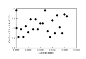
- the building factor F17 of the model transformer was calculated as the value obtained by dividing the model transformer iron loss WT17 /50 by the sample iron loss W17 /50 (WT17 /50 /W17 /50 , no unit). The relationship between this F17 and the La content (unit: mass%) in the base steel sheet was investigated, and the results are shown in Figure 1.
- Figure 1 shows that the building factor F17 can be divided into two groups: good values of 1.25 or less, and high values of 1.30 or more.
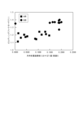
- FIG. 2 shows the results of collating the data in Figure 1 with respect to R18/R17.
- each circle represents a building factor F17, and the larger the diameter of the circle (bubble), the larger the building factor. From the results shown in Figure 2, it was found that there is a relationship of R18/R17 ⁇ 1.50, that is, when the steel belongs to group A and the La content in the base steel plate is in the range of 0.0001 to 0.0200%, a good building factor of 1.25 or less is shown.
- whether each bubble belongs to group A or group B can be determined based on the region in which the circle center of each bubble exists.
- an annealing separator mainly composed of MgO can be applied to one or both surfaces of the primary recrystallized sheet, followed by secondary recrystallization annealing.
- the secondary recrystallization annealing may also serve as purification annealing for purifying the components. This makes it possible to develop the secondary recrystallized structure and form a forsterite coating on the surface of the steel sheet. In this way, a steel sheet with a base coating can be obtained, in which a base coating is formed on the surface of the base steel sheet.
- "mainly composed of MgO” means that the annealing separator contains 75 mass % or more of MgO calculated as a solid content.
- Steel slab A contains C: 0.070%, Si: 3.5%, Mn: 0.07%, Al: 0.0085%, N: 0.0050%, La: 0.0080%, Mo: 0.026%, Ti: 0.0022%, and the balance is Fe and unavoidable impurities.
- Steel slab B contains C: 0.072%, Si: 3.51%, Mn: 0.07%, Al: 0.0080%, N: 0.0047%, La: 0.0100%, Mo: 0.025%, Ti: 0.0020%, and the balance is Fe and unavoidable impurities.
- the hot-rolled sheet was then annealed at 1000°C for 60 seconds in a N2 atmosphere.
- the resulting hot-rolled and annealed sheet was then cold-rolled to a thickness of 0.23 mm.
- the cold-rolled sheet was then subjected to primary recrystallization annealing, which also served as decarburization annealing, at 850°C for 90 seconds in a 60% H2-40 % N2 wet atmosphere with a dew point of 60°C.
- an annealing separator mainly composed of MgO (MgO: 97%) was applied to both surfaces of the base steel sheet (primary recrystallized sheet) after decarburization annealing.
- the annealing separator was prepared by adding TiO2 powder to hot water at 50°C and stirring for 24 hours, and then adding 5 parts by mass of perhydrated TiO2 to the powdered MgO. After that, the steel was held at 1100°C for 25 hours, and then purified by annealing at 1200°C for 10 hours.
- the Ti content of the sample thus obtained i.e., the base steel sheet with a forsterite-based undercoating formed on its surface, was measured according to the method specified in JIS G1223. The results are shown in Table 1. Note that in this example, the Ti content does not change due to the formation of the insulating coating in a later process. Therefore, the measurement results are disclosed in the table as the Ti content in the grain-oriented electrical steel sheet.
- An insulating coating mainly composed of magnesium phosphate and silica was applied onto the undercoat of the steel sheet.
- the iron losses W 17/50 and W 18/50 iron losses when excited to 1.7T and 1.8T, respectively, at 50Hz
- the hysteresis losses Wh 17 and Wh 18 hysteresis losses when excited to 1.7T and 1.8T, respectively
- the annealed intermediate cold-rolled sheet was cold-rolled to finish into a cold-rolled sheet with a sheet thickness of 0.23 mm.
- This cold-rolled sheet was subjected to decarburization annealing at 825°C for 150 seconds in a moist atmosphere of 40% H2-60 % N2 with a dew point of 45°C.
- an annealing separator mainly composed of MgO (MgO: 88%) was applied to the surfaces (both sides) of the obtained decarburized annealed sheet.
- MgO MgO: 88%)
- TiO2 powder was added to hot water at 50 °C, stirred for 24 hours, and then 5 parts by mass of perhydrated TiO2 was added to the powdered MgO.
- purification annealing was performed by holding at 1200°C for 10 hours to form a base coating mainly composed of forsterite. At this time, the heating rate up to 1200°C was 15°C/h.
- an N2 atmosphere was used from room temperature to 700°C
- an atmosphere with various N2 and H2 mixture ratios was used from over 700°C to 1100°C
- an H2 atmosphere was used from over 1100°C to 1200°C.
- an H2 atmosphere was used during holding, and an Ar atmosphere was used during cooling.
- the Ti content of the samples thus obtained i.e., base steel sheets with a forsterite-based undercoating formed on the surface, was measured according to the method specified in JIS G1223. The results are shown in Table 3. Note that in this example, the Ti content does not change due to the formation of an insulating coating in a later process. Therefore, the measurement results are disclosed in the table as the Ti content in the grain-oriented electrical steel sheet.
- An insulating coating mainly composed of magnesium phosphate and silica was applied onto the undercoat of the steel sheet.
- the iron losses W 17/50 and W 18/50 iron losses when excited to 1.7T and 1.8T, respectively, at 50Hz
- the hysteresis losses Wh 17 and Wh 18 hysteresis losses when excited to 1.7T and 1.8T, respectively
- the Ti content of the base steel plate a portion of the obtained sample was immersed in a 10% hydrochloric acid solution at 80°C for 180 seconds to remove the forsterite film and insulating film, and then subjected to measurement according to the method specified in JIS G1223.
- the measurement results are also shown in Table 3.
- the C content of the base steel plate was measured using the same method as in Example 1 and is also shown in Table 3.
- the Ti content in the base steel plate does not change due to the formation of the insulating film.
- the amounts of other elements in the base steel plate were also measured using the same method as in Example 1 and ICP atomic emission spectroscopy, and it was confirmed that the Si content, Mn content, La content, Ga content, and other element contents in the base steel plate were the same as those in each steel slab.
- a three-phase three-legged model transformer was created from the sample with the insulating coating, with an external shape of 500mm square and each leg and yoke having a plate width of 100mm, simulating a transformer.
- the iron loss WT 17/50 transformer iron loss when excited to 1.7T at 50Hz
- the number of sample layers in the model transformer was 50, and they were stacked in pairs.
- the building factor F17 of the model transformer was calculated as the value obtained by dividing the model transformer iron loss WT17 /50 by the sample iron loss W17 /50 (WT17 /50 /W17 /50 ).
- Table 3 As is clear from the table, good core loss characteristics are obtained under conditions within the range of the present invention.
Landscapes
- Chemical & Material Sciences (AREA)
- Engineering & Computer Science (AREA)
- Materials Engineering (AREA)
- Mechanical Engineering (AREA)
- Metallurgy (AREA)
- Organic Chemistry (AREA)
- Physics & Mathematics (AREA)
- Electromagnetism (AREA)
- Dispersion Chemistry (AREA)
- Power Engineering (AREA)
- Manufacturing Of Steel Electrode Plates (AREA)
- Soft Magnetic Materials (AREA)
Priority Applications (1)
| Application Number | Priority Date | Filing Date | Title |
|---|---|---|---|
| JP2025524384A JP7806973B2 (ja) | 2023-12-28 | 2024-12-19 | 方向性電磁鋼板 |
Applications Claiming Priority (2)
| Application Number | Priority Date | Filing Date | Title |
|---|---|---|---|
| JP2023223485 | 2023-12-28 | ||
| JP2023-223485 | 2023-12-28 |
Publications (1)
| Publication Number | Publication Date |
|---|---|
| WO2025142749A1 true WO2025142749A1 (ja) | 2025-07-03 |
Family
ID=96218966
Family Applications (1)
| Application Number | Title | Priority Date | Filing Date |
|---|---|---|---|
| PCT/JP2024/045060 Pending WO2025142749A1 (ja) | 2023-12-28 | 2024-12-19 | 方向性電磁鋼板 |
Country Status (2)
| Country | Link |
|---|---|
| JP (1) | JP7806973B2 (https=) |
| WO (1) | WO2025142749A1 (https=) |
Citations (5)
| Publication number | Priority date | Publication date | Assignee | Title |
|---|---|---|---|---|
| JPH09291313A (ja) * | 1996-04-25 | 1997-11-11 | Kawasaki Steel Corp | 磁気特性・被膜特性に優れる方向性けい素鋼板の製造方法 |
| JP2017020059A (ja) * | 2015-07-08 | 2017-01-26 | Jfeスチール株式会社 | 方向性電磁鋼板とその製造方法 |
| JP2021123766A (ja) * | 2020-02-06 | 2021-08-30 | 日本製鉄株式会社 | 方向性電磁鋼板、および方向性電磁鋼板の製造方法、ならびに焼鈍分離剤 |
| KR20230094748A (ko) * | 2021-12-21 | 2023-06-28 | 주식회사 포스코 | 방향성 전기강판 및 이의 제조방법 |
| WO2024053608A1 (ja) * | 2022-09-09 | 2024-03-14 | Jfeスチール株式会社 | 方向性電磁鋼板 |
-
2024
- 2024-12-19 JP JP2025524384A patent/JP7806973B2/ja active Active
- 2024-12-19 WO PCT/JP2024/045060 patent/WO2025142749A1/ja active Pending
Patent Citations (5)
| Publication number | Priority date | Publication date | Assignee | Title |
|---|---|---|---|---|
| JPH09291313A (ja) * | 1996-04-25 | 1997-11-11 | Kawasaki Steel Corp | 磁気特性・被膜特性に優れる方向性けい素鋼板の製造方法 |
| JP2017020059A (ja) * | 2015-07-08 | 2017-01-26 | Jfeスチール株式会社 | 方向性電磁鋼板とその製造方法 |
| JP2021123766A (ja) * | 2020-02-06 | 2021-08-30 | 日本製鉄株式会社 | 方向性電磁鋼板、および方向性電磁鋼板の製造方法、ならびに焼鈍分離剤 |
| KR20230094748A (ko) * | 2021-12-21 | 2023-06-28 | 주식회사 포스코 | 방향성 전기강판 및 이의 제조방법 |
| WO2024053608A1 (ja) * | 2022-09-09 | 2024-03-14 | Jfeスチール株式会社 | 方向性電磁鋼板 |
Also Published As
| Publication number | Publication date |
|---|---|
| JP7806973B2 (ja) | 2026-01-27 |
| JPWO2025142749A1 (https=) | 2025-07-03 |
Similar Documents
| Publication | Publication Date | Title |
|---|---|---|
| US6562473B1 (en) | Electrical steel sheet suitable for compact iron core and manufacturing method therefor | |
| EP1227163A2 (en) | Grain oriented electrical steel sheet with low iron loss and production method for same | |
| JP7601280B2 (ja) | 方向性電磁鋼板 | |
| WO2012017689A1 (ja) | 方向性電磁鋼板およびその製造方法 | |
| WO2012001952A1 (ja) | 方向性電磁鋼板およびその製造方法 | |
| WO2011115120A1 (ja) | 方向性電磁鋼板の製造方法 | |
| JP4943559B2 (ja) | 方向性電磁鋼板の製造方法 | |
| JP6436316B2 (ja) | 方向性電磁鋼板の製造方法 | |
| CN102197149A (zh) | 方向性电磁钢板的制造方法 | |
| JP7221481B2 (ja) | 方向性電磁鋼板およびその製造方法 | |
| JP7053848B2 (ja) | 方向性電磁鋼板およびその製造方法 | |
| WO2020149341A1 (ja) | 方向性電磁鋼板の製造方法 | |
| JP7806973B2 (ja) | 方向性電磁鋼板 | |
| JPH08288115A (ja) | 鉄損の低い方向性電磁鋼板 | |
| JP7800777B2 (ja) | 方向性電磁鋼板 | |
| JP2000034521A (ja) | 磁気特性に優れる方向性電磁鋼板の製造方法 | |
| WO2025142748A1 (ja) | 方向性電磁鋼板 | |
| JP2014156633A (ja) | 方向性電磁鋼板の製造方法および方向性電磁鋼板並びに方向性電磁鋼板用表面ガラスコーティング | |
| JPH11323438A (ja) | 磁気特性に優れる方向性電磁鋼板の製造方法 | |
| WO2020149333A1 (ja) | 一方向性電磁鋼板の製造方法 | |
| JP2000345305A (ja) | 高磁場鉄損の優れた高磁束密度一方向性電磁鋼板とその製造方法 | |
| JPH0797631A (ja) | 磁気特性および被膜特性に優れた高磁束密度方向性けい素鋼板の製造方法 | |
| CN117396617A (zh) | 取向性电磁钢板的制造方法 | |
| WO2024162442A1 (ja) | 方向性電磁鋼板の製造方法 | |
| JP2002194434A (ja) | 高周波磁気特性および被膜特性に優れた低鉄損方向性電磁鋼板の製造方法 |
Legal Events
| Date | Code | Title | Description |
|---|---|---|---|
| ENP | Entry into the national phase |
Ref document number: 2025524384 Country of ref document: JP Kind code of ref document: A |
|
| WWE | Wipo information: entry into national phase |
Ref document number: 2025524384 Country of ref document: JP |
|
| 121 | Ep: the epo has been informed by wipo that ep was designated in this application |
Ref document number: 24912638 Country of ref document: EP Kind code of ref document: A1 |