WO2025141688A1 - 室外機および冷凍サイクル装置 - Google Patents
室外機および冷凍サイクル装置 Download PDFInfo
- Publication number
- WO2025141688A1 WO2025141688A1 PCT/JP2023/046624 JP2023046624W WO2025141688A1 WO 2025141688 A1 WO2025141688 A1 WO 2025141688A1 JP 2023046624 W JP2023046624 W JP 2023046624W WO 2025141688 A1 WO2025141688 A1 WO 2025141688A1
- Authority
- WO
- WIPO (PCT)
- Prior art keywords
- refrigerant
- outdoor
- outdoor heat
- flow path
- heat exchanger
- Prior art date
- Legal status (The legal status is an assumption and is not a legal conclusion. Google has not performed a legal analysis and makes no representation as to the accuracy of the status listed.)
- Pending
Links
Images


Classifications
-
- F—MECHANICAL ENGINEERING; LIGHTING; HEATING; WEAPONS; BLASTING
- F25—REFRIGERATION OR COOLING; COMBINED HEATING AND REFRIGERATION SYSTEMS; HEAT PUMP SYSTEMS; MANUFACTURE OR STORAGE OF ICE; LIQUEFACTION SOLIDIFICATION OF GASES
- F25B—REFRIGERATION MACHINES, PLANTS OR SYSTEMS; COMBINED HEATING AND REFRIGERATION SYSTEMS; HEAT PUMP SYSTEMS
- F25B47/00—Arrangements for preventing or removing deposits or corrosion, not provided for in another subclass
- F25B47/02—Defrosting cycles
Definitions
- This technology relates to outdoor units and refrigeration cycle devices that have multiple outdoor heat exchangers in the refrigerant circuit. In particular, it relates to defrosting multiple outdoor heat exchangers.
- air conditioning equipment such as multi-air conditioners for buildings has a refrigerant circuit that connects an outdoor unit (outdoor unit), which is a heat source unit placed outside the building, to an indoor unit (indoor unit) placed inside the building via piping.
- Refrigerant circulates in the refrigerant circuit, and the indoor unit heats or cools the air in the room, which is the target space for air conditioning, by utilizing the heat release or absorption of the refrigerant, thereby heating or cooling the target space for air conditioning.
- an air conditioner has been proposed that includes an outdoor unit that can switch the flow of refrigerant in multiple outdoor heat exchangers between cooling and heating operation (see, for example, Patent Document 1).
- this air conditioner when multiple outdoor heat exchangers function as evaporators, the piping connections are switched so that the refrigerant flows in parallel to each outdoor heat exchanger in the refrigerant circuit, and when they function as condensers, the refrigerant flows in series to each outdoor heat exchanger.
- the pressure loss in the evaporator can be reduced, improving the performance of the evaporator and the heating performance.
- the flow rate of the refrigerant passing through the condenser can be increased, improving the performance of the condenser and the cooling performance.
- the air conditioner performs defrosting operation (defrosting operation) as necessary, in which the refrigerant discharged from the compressor is guided as hot gas to the outdoor heat exchanger that serves as an evaporator, and the frost on the heat exchanger surface is melted and removed.
- defrosting operation the outdoor heat exchanger serves as a condenser, so the flow path is the same as that in cooling operation.
- the flow path is one in which the refrigerant flows in series.
- the refrigerant flows in series through multiple outdoor heat exchangers, a large amount of heat is released in the outdoor heat exchanger upstream of the refrigerant flow from the compressor as the high-temperature refrigerant passes through, but the temperature of the refrigerant decreases as it moves downstream, and the amount of heat released gradually decreases.
- the outdoor unit is an outdoor unit for an air conditioner having a refrigerant circuit in which a refrigerant circulates through a flow path formed by piping connection with an indoor unit, and is equipped with a compressor that compresses and discharges the refrigerant, a number of outdoor heat exchangers that exchange heat with the air outside the space to be air-conditioned, and a refrigerant flow path switching device that switches between a flow path in which the refrigerant passes through the multiple outdoor heat exchangers in parallel and a flow path in which the refrigerant passes through in series, and during defrosting operation, the refrigerant flow path switching device switches to a flow path in which the refrigerant discharged from the compressor passes through the multiple outdoor heat exchangers in parallel.
- the refrigeration cycle device disclosed herein also includes the outdoor unit described above and an indoor unit that receives heat from the outdoor unit and heats or cools an object.
- the outdoor unit and refrigeration cycle device disclosed herein can improve operating performance and efficiency.
- FIG. 1 is a diagram showing an example of the configuration of an air conditioning apparatus according to a first embodiment.
- FIG. FIG. 4 is a diagram illustrating a flow of a refrigerant in a heating operation according to the first embodiment.
- FIG. 4 is a diagram illustrating a flow of a refrigerant during cooling operation according to the first embodiment.
- FIG. 4 is a diagram illustrating a flow of a refrigerant in a defrosting operation according to the first embodiment.
- FIG. 11 is a diagram showing an example of the configuration of an air conditioning apparatus according to a second embodiment.
- FIG. 11 is a diagram illustrating the flow of refrigerant during a defrosting operation according to the second embodiment.
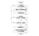
- FIG. 11 is a diagram illustrating a process flow in a control device according to a third embodiment.
- Fig. 1 is a diagram showing an example of the configuration of an air-conditioning device 1 according to embodiment 1.
- the air-conditioning device 1 will be described as an example of a refrigeration cycle device having a heat exchanger according to embodiment 1.
- Fig. 1 functionally shows the connection relationship and arrangement configuration of each device in the air-conditioning device 1, and does not necessarily show the arrangement relationship in physical space (the same applies to the following figures).
- the air conditioning device 1 is a device that adjusts the temperature of the air in the indoor space that is the target of air conditioning.
- FIG. 1 shows an example of a configuration in which one indoor unit 400 and one outdoor unit 100 are connected via two main pipes 500.
- the number of indoor units 400 connected to the outdoor unit 100 is not limited to one, and multiple units may be connected.
- the air conditioning device 1 in the first embodiment is configured by connecting the outdoor unit 100 and the indoor unit 400 with a main pipe 500, and has a refrigerant circuit through which a refrigerant circulates.
- the flow path through which the refrigerant flows changes in the outdoor heat exchanger 130, as described below.
- the refrigerant filled in the refrigerant circuit is not particularly limited.
- the outdoor unit 100 has, as main components of a refrigerant circuit, a compressor 110, a cooling/heating flow path switching device 120, an outdoor heat exchanger 130, an outdoor expansion valve 140, a check valve 150, an accumulator 160, and an outdoor shut-off valve 170.
- the compressor 110, the cooling/heating flow path switching device 120, the outdoor heat exchanger 130, the outdoor expansion valve 140, the check valve 150, the accumulator 160, and the outdoor shut-off valve 170 are connected by piping that constitutes the refrigerant circuit within the outdoor unit 100, and are devices that constitute a part of the refrigerant circuit.
- the compressor 110 compresses the sucked refrigerant and discharges it.
- the compressor 110 is, for example, a scroll compressor, a reciprocating compressor, or a vane compressor.
- the air conditioning device 1 in embodiment 1 has, for example, an inverter device (not shown) and can arbitrarily change the drive frequency of the power supplied to the compressor 110. Therefore, the compressor 110 can change the drive frequency based on instructions from the control device 600 (described later), thereby changing the rotation speed of the motor (not shown) of the compressor 110 and changing the drive capacity.
- the outdoor expansion valve 140 is, for example, an electronic expansion valve that reduces the pressure of the refrigerant during heating operation to expand it and adjust the amount of refrigerant flowing into the outdoor heat exchanger 130.
- the air conditioning device 1 in embodiment 1 has outdoor expansion valves 140a and 140b corresponding to the outdoor heat exchangers 130a and 130b.
- the bypass flow path 300 is a flow path through which hot gas, which is a refrigerant discharged from the compressor 110, flows when defrosting the outdoor heat exchanger 130 in defrosting operation.
- the bypass flow path 300 has a bypass pipe 310 and a bypass control valve 320.
- One end of the bypass pipe 310 is connected to a pipe on the discharge side of the compressor 110, and the other end is connected to a pipe connecting the outdoor heat exchanger 130b and the outdoor expansion valve 140b.
- the bypass control valve 320 which is one of the refrigerant flow path switching devices, is an opening/closing valve such as a solenoid valve that controls whether or not to pass the refrigerant through the bypass pipe 310 based on an instruction from the control device 600 described later.
- the bypass control valve 320 is opened during defrosting operation and closed during other operations.
- the indoor unit 400 is, for example, a unit installed indoors.
- the indoor unit 400 has an indoor expansion valve 410, an indoor heat exchanger 420, and an indoor fan 430.
- the indoor expansion valve 410 and the indoor heat exchanger 420 are connected by piping within the indoor unit 400, and are devices that constitute a part of the refrigerant circuit.
- the indoor expansion valve 410 which serves as a throttling device, has a valve such as an electronic expansion valve or a temperature-sensing expansion valve.
- the indoor expansion valve 410 is a valve that adjusts the pressure and flow rate of the refrigerant passing through the indoor heat exchanger 420.
- the indoor heat exchanger 420 in the first embodiment is, for example, a fin-and-tube type heat exchanger having a plurality of heat transfer tubes and a plurality of fins.
- the indoor heat exchanger 420 functions as a condenser during heating operation, and exchanges heat between the refrigerant discharged by the compressor 110 in the outdoor unit 100 and the indoor air, condensing the refrigerant to liquefy or to form a two-phase gas-liquid mixture, and heating the indoor air.
- the indoor heat exchanger 420 functions as an evaporator during cooling operation, and exchanges heat between the refrigerant flowing in from the indoor expansion valve 410 side and the indoor air, evaporating the refrigerant to vaporize it, and cooling the indoor air.
- the indoor fan 430 is disposed near the indoor heat exchanger 420, and is a blower that sends air to the indoor heat exchanger 420 and sends the conditioned air into the room.
- the air conditioning apparatus 1 also has a control device 600.
- the control device 600 is a device that controls the air conditioning apparatus 1.
- the outdoor unit 100 is described as having the control device 600, but this is not limited to this.
- Another unit may have the control device 600.
- the control device 600 may be a device independent of the unit that has the devices that make up the air conditioning apparatus 1.
- the air conditioning device 1 in the first embodiment has various sensors as a sensor unit that detect physical quantities used when the control device 600 performs processes such as judgments and sends detection signals to the control device 600.
- the air conditioning device 1 has a high-pressure sensor 710, a refrigerant temperature sensor 720, and an outdoor air temperature sensor 730 as a sensor unit.
- the high-pressure sensor 710 is installed on the discharge side of the compressor 110 and is a sensor that detects the pressure of the refrigerant on the high-pressure side of the refrigerant circuit as the high-pressure pressure.
- the refrigerant temperature sensor 720 is a sensor that detects the refrigerant temperature of the refrigerant flowing out from the outdoor heat exchanger 130 when the outdoor heat exchanger 130 functions as a condenser.
- the refrigerant temperature sensor 720 is installed downstream of the branch pipe 180 in the flow of the refrigerant during cooling operation and defrosting operation.
- the outdoor air temperature sensor 730 is a sensor that detects the temperature of the outdoor air.
- FIG. 2 is a diagram for explaining the flow of refrigerant in heating operation according to the first embodiment.
- the operation of each device of the air conditioning device 1 will be explained based on the flow of refrigerant.
- the operation of each device of the refrigerant circuit in heating operation will be explained based on the flow of refrigerant.
- the solid arrows in FIG. 2 indicate the flow of refrigerant in heating operation.
- the high-temperature and high-pressure gaseous refrigerant (hereinafter referred to as gas refrigerant) compressed and discharged by the compressor 110 passes through the cooling/heating flow switching device 120 and flows out of the outdoor unit 100.
- gas refrigerant gas refrigerant
- the refrigerant that flows out of the outdoor unit 100 passes through the main pipe 500 and flows into the indoor heat exchanger 420 of the indoor unit 400. While passing through the indoor heat exchanger 420, the gas refrigerant condenses and liquefies by, for example, exchanging heat with the air in the space to be air-conditioned, and becomes a liquid refrigerant (hereinafter referred to as liquid refrigerant).
- liquid refrigerant a liquid refrigerant
- the condensed and liquefied liquid refrigerant passes through the indoor expansion valve 410.
- the refrigerant is decompressed when passing through the indoor expansion valve 410.
- the refrigerant that has been depressurized by the indoor expansion valve 410 and is in a two-phase gas-liquid state flows out of the indoor unit 400.
- the refrigerant that flows out of the indoor unit 400 passes through the main pipe 500 and flows into the outdoor unit 100.
- the refrigerant that flows into the outdoor unit 100 branches at the branch pipe 180 and passes through the outdoor expansion valve 140a and the outdoor expansion valve 140b, respectively.
- the outdoor expansion valves 140a and 140b reduce the pressure of the refrigerant and adjust the amount of refrigerant.
- the refrigerant that has passed through the outdoor expansion valves 140a and 140b passes through the outdoor heat exchangers 130a and 130b, respectively. In the outdoor heat exchanger 130a and the outdoor heat exchanger 130b, the refrigerant exchanges heat with the outdoor air sent from the outdoor fan 190, and evaporates.
- the gasified gas refrigerant passes through the hot/cold flow path switching device 120 and the accumulator 160, and is sucked back into the compressor 110. In this manner, the refrigerant circulates in the refrigerant circuit of the air conditioner 1, and air conditioning related to heating is performed.
- FIG 3 is a diagram explaining the flow of refrigerant in cooling operation according to embodiment 1. Next, cooling operation will be explained.
- the solid arrows in Figure 3 indicate the flow of refrigerant in cooling operation.
- the heat exchange switching valve 220 is opened, and the outdoor expansion valve 140a is closed so that the refrigerant does not pass through.
- the high-temperature and high-pressure gas refrigerant compressed and discharged by the compressor 110 passes through the cooling/heating flow path switching device 120 and flows into the outdoor heat exchanger 130a.
- the refrigerant that flows into the outdoor heat exchanger 130a passes through the outdoor heat exchanger 130a, the heat exchange switching piping 210 of the heat exchange switching flow path 200, and the outdoor heat exchanger 130a in that order.
- the refrigerant condenses and liquefies by exchanging heat with the outdoor air supplied by the outdoor fan 190 in the outdoor heat exchanger 130a and the outdoor heat exchanger 130b.
- the liquid refrigerant that has passed through the outdoor heat exchanger 130 flows out of the outdoor unit 100.
- the refrigerant that has flowed out of the outdoor unit 100 passes through the main pipe 500 and the indoor expansion valve 410 of the indoor unit 400.
- the refrigerant is decompressed when passing through the indoor expansion valve 410 and becomes a two-phase gas-liquid state.
- the refrigerant that has been decompressed and become a two-phase gas-liquid state by the indoor expansion valve 410 passes through the indoor heat exchanger 420.
- the refrigerant is evaporated by heat exchange with indoor air, and the gasified gas refrigerant flows out of the indoor unit 400.
- the refrigerant that has flowed out of the indoor unit 400 passes through the main pipe 500 and flows into the outdoor unit 100.
- the refrigerant that has flowed into the outdoor unit 100 passes through the cooling/heating flow switching device 120 and is sucked into the compressor 110 again. In this manner, the refrigerant circulates in the refrigerant circuit of the air conditioner 1, and air conditioning related to cooling is performed.
- Some of the high-temperature and high-pressure gas refrigerant compressed and discharged by the compressor 110 passes through the hot/cold flow path switching device 120 and flows into the outdoor heat exchanger 130a as hot gas.
- the other gas refrigerant passes through the bypass piping 310 and flows into the outdoor heat exchanger 130b as hot gas.
- the refrigerants that flow into the outdoor heat exchanger 130a and the outdoor heat exchanger 130b are liquefied by exchanging heat with the frost on the outdoor heat exchanger 130a and the outdoor heat exchanger 130b.
- the refrigerant that flows into the outdoor unit 100 passes through the cooling/heating flow switching device 120 and the accumulator 160, and is sucked into the compressor 110 again. In this way, the refrigerant circulates in the refrigerant circuit of the air conditioner 1, and defrosting operation is performed.
- the outdoor unit 100 of the air conditioning device 1 in embodiment 1 is equipped with a refrigerant flow path switching device that switches the flow paths in the multiple outdoor heat exchangers 130.
- the cooling/heating flow path switching device 120 four-way valve 120a and four-way valve 120b
- the heat exchange switching valve 220 and the bypass control valve 320 are the refrigerant flow path switching device. Therefore, it is possible to pass hot gas directly through the outdoor heat exchanger 130b and pass hot gas in parallel through the multiple outdoor heat exchangers 130.
- the outdoor unit 100 of the air conditioning device 1 in the first embodiment can shorten the defrosting time and shorten the time from defrosting operation to heating operation, thereby improving the overall efficiency of operation when heating the room.
- a time reduction of about 20% can be expected compared to when hot gas is passed through multiple outdoor heat exchangers 130 in series.
- the outdoor unit 100 in the first embodiment includes a bypass flow path 300 having a bypass pipe 310 and a bypass control valve 320. Therefore, in the outdoor unit 100 configured with a switching device that passes refrigerant in parallel through multiple outdoor heat exchangers 130 during cooling operation and passes refrigerant in parallel through multiple outdoor heat exchangers 130 during heating operation, hot gas can be passed in parallel through multiple outdoor heat exchangers 130 during defrosting operation.
- FIG. 5 is a diagram showing an example of the configuration of the air conditioning apparatus 1 according to the second embodiment.
- the devices and the like with the same reference numerals as those in FIG. 1 perform the same operations as those described in the first embodiment.
- the outdoor unit 100 of the air conditioning apparatus 1 in the second embodiment is provided with an opening/closing control valve 151 instead of the check valve 150.
- the outdoor unit 100 in the second embodiment does not have a bypass flow path 300.
- the cooling/heating flow path switching device 120 (four-way valve 120a and four-way valve 120b), the heat exchange switching valve 220, and the opening/closing control valve 151 serve as the refrigerant flow path switching device.
- the on-off control valve 151 is an on-off valve such as a solenoid valve that controls the passage of refrigerant through the piping connecting the four-way valve 120b of the cooling/heating flow path switching device 120 and the outdoor heat exchanger 130b.
- the on-off control valve 151 opens during heating operation and closes during cooling operation.
- the on-off control valve 151 does not allow the refrigerant discharged from the compressor 110 to pass, but allows the refrigerant that has passed through the outdoor heat exchanger 130b to pass. Therefore, the refrigerant in the refrigerant circuit flows in the same manner as in cooling operation and heating operation.
- the on-off control valve 151 opens.
- hot gas which is the refrigerant discharged from the compressor 110, flows in parallel into the outdoor heat exchanger 130a and the outdoor heat exchanger 130b.
- the refrigerant that flows into the outdoor unit 100 passes through the hot/cold flow switching device 120 and the accumulator 160, and is sucked into the compressor 110 again. In this manner, the refrigerant in the air conditioning device 1 circulates and performs defrosting operation.
- the air conditioning device 1 in the second embodiment has an on-off control valve 151 between the four-way valve 120b of the cooling/heating flow switching device 120 and the outdoor heat exchanger 130b, which can control the passage of the refrigerant by opening and closing.
- the on-off control valve 151 can allow not only the refrigerant flowing from the outdoor heat exchanger 130b to the four-way valve 120b, but also the refrigerant discharged by the compressor 110 to flow into the outdoor heat exchanger 130b via the four-way valve 120b. Therefore, no refrigerant is allowed to pass during cooling operation, and the refrigerant discharged by the compressor 110 can be allowed to pass as hot gas during defrosting operation, and hot gas can be allowed to pass through multiple outdoor heat exchangers 130 in parallel. This shortens the defrosting time and speeds up the transition time from defrosting operation to heating operation, thereby improving overall operating efficiency.
- Embodiment 3 a description will be given of the defrosting operation termination determination performed by the control device 600 of the air conditioning apparatus 1.
- the air conditioning apparatus 1 in the third embodiment is assumed to have the same configuration as the air conditioning apparatus 1 described in the first embodiment. However, this is not limited to this, and the present invention can also be applied to the air conditioning apparatus 1 in the second embodiment.
- the control device 600 basically terminates the defrosting operation and transitions to heating operation when it determines that the frost on the outdoor heat exchanger 130 has completely melted based on the refrigerant temperature detected by the refrigerant temperature sensor 720. For example, the refrigerant that becomes hot gas passing through the outdoor heat exchanger 130 releases heat through heat exchange with the frost on the outdoor heat exchanger 130, lowering the refrigerant temperature. Then, when the frost has completely melted, heat exchange between the refrigerant and the frost ceases and the amount of heat exchanged decreases. Therefore, the refrigerant temperature rises. Therefore, the control device 600 terminates the defrosting operation of the air conditioning device 1 when the refrigerant temperature reaches or exceeds the temperature represented by the operation termination judgment threshold, which is the criterion for judging the termination of the defrosting operation.
Landscapes
- Engineering & Computer Science (AREA)
- Physics & Mathematics (AREA)
- Mechanical Engineering (AREA)
- Thermal Sciences (AREA)
- General Engineering & Computer Science (AREA)
- Air Conditioning Control Device (AREA)
Priority Applications (2)
| Application Number | Priority Date | Filing Date | Title |
|---|---|---|---|
| JP2025565773A JPWO2025141688A1 (https=) | 2023-12-26 | 2023-12-26 | |
| PCT/JP2023/046624 WO2025141688A1 (ja) | 2023-12-26 | 2023-12-26 | 室外機および冷凍サイクル装置 |
Applications Claiming Priority (1)
| Application Number | Priority Date | Filing Date | Title |
|---|---|---|---|
| PCT/JP2023/046624 WO2025141688A1 (ja) | 2023-12-26 | 2023-12-26 | 室外機および冷凍サイクル装置 |
Publications (1)
| Publication Number | Publication Date |
|---|---|
| WO2025141688A1 true WO2025141688A1 (ja) | 2025-07-03 |
Family
ID=96217071
Family Applications (1)
| Application Number | Title | Priority Date | Filing Date |
|---|---|---|---|
| PCT/JP2023/046624 Pending WO2025141688A1 (ja) | 2023-12-26 | 2023-12-26 | 室外機および冷凍サイクル装置 |
Country Status (2)
| Country | Link |
|---|---|
| JP (1) | JPWO2025141688A1 (https=) |
| WO (1) | WO2025141688A1 (https=) |
Citations (7)
| Publication number | Priority date | Publication date | Assignee | Title |
|---|---|---|---|---|
| JP2013061091A (ja) * | 2011-09-12 | 2013-04-04 | Daikin Industries Ltd | 冷凍装置 |
| JP2015064169A (ja) * | 2013-09-26 | 2015-04-09 | パナソニックIpマネジメント株式会社 | 温水生成装置 |
| WO2015059945A1 (ja) * | 2013-10-24 | 2015-04-30 | 三菱電機株式会社 | 空気調和装置 |
| WO2017006596A1 (ja) * | 2015-07-06 | 2017-01-12 | 三菱電機株式会社 | 冷凍サイクル装置 |
| WO2018047416A1 (ja) * | 2016-09-12 | 2018-03-15 | 三菱電機株式会社 | 空気調和装置 |
| JP6463491B2 (ja) * | 2015-08-28 | 2019-02-06 | 三菱電機株式会社 | 冷凍サイクル装置 |
| WO2023218585A1 (ja) * | 2022-05-12 | 2023-11-16 | 三菱電機株式会社 | 冷凍サイクル装置 |
-
2023
- 2023-12-26 JP JP2025565773A patent/JPWO2025141688A1/ja active Pending
- 2023-12-26 WO PCT/JP2023/046624 patent/WO2025141688A1/ja active Pending
Patent Citations (7)
| Publication number | Priority date | Publication date | Assignee | Title |
|---|---|---|---|---|
| JP2013061091A (ja) * | 2011-09-12 | 2013-04-04 | Daikin Industries Ltd | 冷凍装置 |
| JP2015064169A (ja) * | 2013-09-26 | 2015-04-09 | パナソニックIpマネジメント株式会社 | 温水生成装置 |
| WO2015059945A1 (ja) * | 2013-10-24 | 2015-04-30 | 三菱電機株式会社 | 空気調和装置 |
| WO2017006596A1 (ja) * | 2015-07-06 | 2017-01-12 | 三菱電機株式会社 | 冷凍サイクル装置 |
| JP6463491B2 (ja) * | 2015-08-28 | 2019-02-06 | 三菱電機株式会社 | 冷凍サイクル装置 |
| WO2018047416A1 (ja) * | 2016-09-12 | 2018-03-15 | 三菱電機株式会社 | 空気調和装置 |
| WO2023218585A1 (ja) * | 2022-05-12 | 2023-11-16 | 三菱電機株式会社 | 冷凍サイクル装置 |
Also Published As
| Publication number | Publication date |
|---|---|
| JPWO2025141688A1 (https=) | 2025-07-03 |
Similar Documents
| Publication | Publication Date | Title |
|---|---|---|
| KR101096822B1 (ko) | 냉동장치 | |
| JP5125116B2 (ja) | 冷凍装置 | |
| CN101449117B (zh) | 冷冻装置 | |
| JP4704728B2 (ja) | 空調機の冷媒温度制御装置及び制御方法 | |
| JP5310101B2 (ja) | 空気調和装置 | |
| CN112050399B (zh) | 一种空调装置 | |
| JP7496938B2 (ja) | 空気調和装置 | |
| JPH1068553A (ja) | 空気調和機 | |
| JP2017142038A (ja) | 冷凍サイクル装置 | |
| WO2023175656A1 (ja) | 空気調和装置 | |
| CN213089945U (zh) | 一种空调装置 | |
| KR101692243B1 (ko) | 캐스캐이드 사이클을 이용한 히트 펌프 | |
| KR101203995B1 (ko) | 공기조화기 및 그 제상운전방법 | |
| JP7512650B2 (ja) | 空気調和機 | |
| JP7615415B1 (ja) | 空気調和装置 | |
| WO2018167961A1 (ja) | 空気調和機 | |
| US20260036342A1 (en) | Cascade refrigeration system | |
| JP7750099B2 (ja) | 空気調和機 | |
| JP7378671B1 (ja) | 空気調和装置 | |
| WO2025141688A1 (ja) | 室外機および冷凍サイクル装置 | |
| JP2007139257A (ja) | 冷凍装置 | |
| WO2021192074A1 (ja) | 空気調和機 | |
| WO2024176371A1 (ja) | 空気調和装置 | |
| JP6704513B2 (ja) | 冷凍サイクル装置 | |
| KR20050080601A (ko) | 멀티공기조화기의 제어방법 |
Legal Events
| Date | Code | Title | Description |
|---|---|---|---|
| 121 | Ep: the epo has been informed by wipo that ep was designated in this application |
Ref document number: 23963044 Country of ref document: EP Kind code of ref document: A1 |
|
| ENP | Entry into the national phase |
Ref document number: 2025565773 Country of ref document: JP Kind code of ref document: A |
|
| WWE | Wipo information: entry into national phase |
Ref document number: 2025565773 Country of ref document: JP |