WO2025120835A1 - 内燃機関 - Google Patents
内燃機関 Download PDFInfo
- Publication number
- WO2025120835A1 WO2025120835A1 PCT/JP2023/043966 JP2023043966W WO2025120835A1 WO 2025120835 A1 WO2025120835 A1 WO 2025120835A1 JP 2023043966 W JP2023043966 W JP 2023043966W WO 2025120835 A1 WO2025120835 A1 WO 2025120835A1
- Authority
- WO
- WIPO (PCT)
- Prior art keywords
- turbocharger
- exhaust
- purification device
- supercharger
- internal combustion
- Prior art date
- Legal status (The legal status is an assumption and is not a legal conclusion. Google has not performed a legal analysis and makes no representation as to the accuracy of the status listed.)
- Pending
Links
Images

Classifications
-
- F—MECHANICAL ENGINEERING; LIGHTING; HEATING; WEAPONS; BLASTING
- F01—MACHINES OR ENGINES IN GENERAL; ENGINE PLANTS IN GENERAL; STEAM ENGINES
- F01N—GAS-FLOW SILENCERS OR EXHAUST APPARATUS FOR MACHINES OR ENGINES IN GENERAL; GAS-FLOW SILENCERS OR EXHAUST APPARATUS FOR INTERNAL-COMBUSTION ENGINES
- F01N3/00—Exhaust or silencing apparatus having means for purifying, rendering innocuous, or otherwise treating exhaust
- F01N3/08—Exhaust or silencing apparatus having means for purifying, rendering innocuous, or otherwise treating exhaust for rendering innocuous
- F01N3/10—Exhaust or silencing apparatus having means for purifying, rendering innocuous, or otherwise treating exhaust for rendering innocuous by thermal or catalytic conversion of noxious components of exhaust
- F01N3/18—Exhaust or silencing apparatus having means for purifying, rendering innocuous, or otherwise treating exhaust for rendering innocuous by thermal or catalytic conversion of noxious components of exhaust characterised by methods of operation; Control
- F01N3/20—Exhaust or silencing apparatus having means for purifying, rendering innocuous, or otherwise treating exhaust for rendering innocuous by thermal or catalytic conversion of noxious components of exhaust characterised by methods of operation; Control specially adapted for catalytic conversion
-
- F—MECHANICAL ENGINEERING; LIGHTING; HEATING; WEAPONS; BLASTING
- F02—COMBUSTION ENGINES; HOT-GAS OR COMBUSTION-PRODUCT ENGINE PLANTS
- F02B—INTERNAL-COMBUSTION PISTON ENGINES; COMBUSTION ENGINES IN GENERAL
- F02B29/00—Engines characterised by provision for charging or scavenging not provided for in groups F02B25/00, F02B27/00 or F02B33/00 - F02B39/00; Details thereof
- F02B29/04—Cooling of air intake supply
-
- F—MECHANICAL ENGINEERING; LIGHTING; HEATING; WEAPONS; BLASTING
- F02—COMBUSTION ENGINES; HOT-GAS OR COMBUSTION-PRODUCT ENGINE PLANTS
- F02B—INTERNAL-COMBUSTION PISTON ENGINES; COMBUSTION ENGINES IN GENERAL
- F02B37/00—Engines characterised by provision of pumps driven at least for part of the time by exhaust
-
- F—MECHANICAL ENGINEERING; LIGHTING; HEATING; WEAPONS; BLASTING
- F02—COMBUSTION ENGINES; HOT-GAS OR COMBUSTION-PRODUCT ENGINE PLANTS
- F02B—INTERNAL-COMBUSTION PISTON ENGINES; COMBUSTION ENGINES IN GENERAL
- F02B37/00—Engines characterised by provision of pumps driven at least for part of the time by exhaust
- F02B37/013—Engines characterised by provision of pumps driven at least for part of the time by exhaust with exhaust-driven pumps arranged in series
Definitions
- the present invention relates to an internal combustion engine that uses two turbochargers in combination.
- an internal combustion engine called a two-stage turbo engine, which is equipped with two turbochargers having different capacities (see Patent Document 1).
- This internal combustion engine is equipped with a first turbocharger provided upstream of the exhaust passage and a second turbocharger provided downstream thereof with a larger capacity than the first turbocharger; in the low to medium rotation range of the internal combustion engine, turbocharging is efficiently performed mainly by the first turbocharger with a smaller capacity, and in the medium to high rotation range of the internal combustion engine, turbocharging is efficiently performed mainly by the second turbocharger with a larger capacity.
- an exhaust gas purification device is provided downstream of the second turbocharger in the exhaust passage, and the exhaust gas purification device includes an oxidation catalyst (DOC) or a three-way catalyst (TWC) that purifies the exhaust gas, and a particulate filter that is disposed downstream of the catalyst and collects particulates in the exhaust gas.
- the catalyst exerts its performance when its temperature is raised to its activation temperature, so that the temperature is preferably maintained at a relatively high level.
- the particulate filter is regenerated by burning the trapped particulates, it is preferable that the particulate filter be maintained at a relatively high temperature.
- the first turbocharger and the second turbocharger since high-temperature exhaust gas flows through the first turbocharger and the second turbocharger, the first turbocharger and the second turbocharger become hot, and the heat radiated from the first turbocharger and the second turbocharger is transferred to the surroundings. Therefore, it is conceivable to use this transferred heat to heat the exhaust gas purification device, thereby improving the exhaust gas purification performance of the exhaust gas purification device.
- the second turbocharger is disposed below the first turbocharger, and the exhaust purification device is disposed at a location further below and away from the second turbocharger, making it difficult for heat from the first turbocharger and the second turbocharger to be transferred to the exhaust purification device.
- the present invention has been made in consideration of the above circumstances, and an object of the present invention is to provide an internal combustion engine that is advantageous in improving the exhaust purification performance of the exhaust purification device by utilizing heat from a first turbocharger and a second turbocharger to heat the exhaust purification device.
- one embodiment of the present invention comprises a first turbocharger connected to an exhaust passage of an internal combustion engine, a second turbocharger connected to the first turbocharger and arranged side by side with the first turbocharger, and an exhaust purification device connected to the second turbocharger and extending from a side of the second turbocharger to a side of the first turbocharger, and is characterized in that the exhaust purification device is arranged adjacent to the first turbocharger and the second turbocharger.
- one embodiment of the present invention is characterized in that the exhaust purification device includes a catalyst that purifies exhaust gas, and a particulate filter that is disposed downstream of the catalyst and collects particulates in the exhaust gas, the catalyst being adjacent to the second turbocharger, and the particulate filter being adjacent to the first turbocharger. Furthermore, one embodiment of the present invention is characterized in that the exhaust purification device extends in a vertical direction on a side of the engine body in a vehicle width direction, and the first turbocharger and the second turbocharger are arranged side by side vertically in front of the exhaust purification device.
- one embodiment of the present invention is characterized in that an intercooler that cools intake air is provided in front of the first turbocharger, the exhaust purification device extends below the first turbocharger, and a portion of the exhaust purification device located below the first turbocharger overlaps with the intercooler in the vehicle fore-and-aft direction.
- one embodiment of the present invention is characterized in that the second turbocharger is used in the higher rotation range than the first turbocharger, and the second turbocharger does not overlap with the intercooler in the front-to-rear direction of the vehicle.
- the engine includes a first turbocharger, a second turbocharger connected to the first turbocharger and arranged side by side with the first turbocharger, and an exhaust gas purification device connected to the second turbocharger and extending from the second turbocharger side to the first turbocharger side, and the exhaust gas purification device is arranged adjacent to the first turbocharger and the second turbocharger.
- the entire exhaust purification device is heated by the first turbocharger and the second turbocharger, which is advantageous in suppressing a drop in temperature of the exhaust purification device and in suppressing a drop in temperature of the catalyst, thereby improving the exhaust purification performance of the exhaust purification device.
- the exhaust gas purification device comprises a catalyst and a particulate filter arranged downstream of the catalyst, the catalyst being adjacent to the second turbocharger, and the particulate filter being adjacent to the first turbocharger
- heat from the second turbocharger is transferred to the catalyst, thereby efficiently heating the catalyst, which is advantageous for improving exhaust gas purification performance
- heat from the first turbocharger, which has a higher temperature than the second turbocharger is transferred to the particulate filter, thereby heating the particulate filter, which can suppress a drop in temperature of the particulate filter, which is advantageous for efficiently performing regeneration processing of the particulate filter.
- the traveling wind is blocked by the first turbocharger and the second turbocharger, preventing the traveling wind from directly hitting the exhaust purification device, which is advantageous in preventing a drop in temperature of the exhaust purification device due to the traveling wind and is more advantageous in improving the exhaust purification performance of the exhaust purification device.
- the exhaust purification device extends below the first turbocharger, and the portion of the exhaust purification device located below the first turbocharger overlaps with the intercooler in the fore-and-aft direction of the vehicle, this is advantageous in preventing the first turbocharger from being excessively cooled by the wind from traveling, the temperature of which has increased by passing through the intercooler, and is therefore more advantageous in preventing a drop in temperature of the exhaust purification device and improving the exhaust purification performance of the exhaust purification device.
- the traveling wind hits the second supercharger directly without passing through the intercooler, so that the second supercharger is efficiently cooled by the traveling wind. Therefore, it is possible to suppress the rise in temperature of the intake air pressure-fed from the second supercharger to the engine body, which is advantageous in improving the charging efficiency of the internal combustion engine and increasing the output of the internal combustion engine.
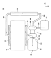
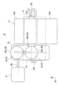
- 1 is a side view of an internal combustion device according to an embodiment, as viewed in a vehicle width direction. 1 is a plan view of an internal combustion device according to an embodiment, as viewed from above; 1 is a front view of an internal combustion device according to an embodiment, as viewed from the front of a vehicle.
- the symbol FR indicates the front of the vehicle
- the symbol RH indicates the vehicle width direction
- the symbol UP indicates the upper side of the vehicle.
- the internal combustion engine is a diesel engine that uses light oil as fuel, but the present invention is of course also applicable to an internal combustion engine that uses gasoline as fuel.
- the internal combustion engine 10 includes an engine body 12, an air cleaner 14, an intercooler 16, a supercharger 18, an exhaust purification device 20, and an engine ECU (not shown) that controls the engine body 12 and the supercharger 18, and in this embodiment, the internal combustion engine 10 is disposed in a space in front of the vehicle in front of the dash panel.
- the engine body 12 includes a cylinder head 1202 and a cylinder block 1204 connected to the lower part of the cylinder head 1202, and a valve mechanism 1206 that operates the intake valve and exhaust valve is provided on the upper part of the cylinder head 1202.
- an intake manifold 22 that supplies intake air to each cylinder chamber is connected to a side wall of the cylinder head 1202 facing one side in the vehicle width direction.
- An exhaust manifold 24, through which exhaust gas is discharged from each cylinder chamber, is connected to the side wall of the cylinder head 1202 facing the other side in the vehicle width direction, and as shown in FIG. 1, a downstream end 2402 of the exhaust manifold 24 is connected to a first turbine housing 28A of a first supercharger 28 of the supercharging device 18, which will be described later.
- the air cleaner 14 removes dust from the intake air, and is connected via a first intake pipe 26A to a second compressor housing 30B of a second supercharger 30 of the supercharging device 18, which will be described later.
- the intercooler 16 uses a refrigerant to cool the intake air, which has become hot after being compressed by the first turbocharger 28 and the second turbocharger 30.
- the refrigerant whose temperature has increased by absorbing heat from the intake air, is cooled by the running wind passing through the intercooler 16. As shown in FIG.
- the intake inlet of the intercooler 16 is connected to the first compressor housing 28B of the first turbocharger 28 via the second intake pipe 26B, and the intake outlet of the intercooler 16 is connected to the upstream end of the intake manifold 22 via the third intake pipe 26C.
- the intercooler 16 has a horizontally long rectangular plate shape with its longitudinal direction oriented in the vehicle width direction and its thickness direction oriented in the vehicle fore-and-aft direction, and is provided in front of the first turbocharger 28, and as shown in Figure 3, the intercooler 16 and the first turbocharger 28 overlap in the vehicle fore-and-aft direction.
- the intercooler 16 and the second supercharger 30 do not overlap in the front-rear direction of the vehicle, and the second supercharger 30 protrudes above the intercooler 16 .
- the first supercharger 28 is located within the outline of the intercooler 16
- the second supercharger 30 is located outside the outline of the intercooler 16 .
- the supercharger 18 is a two-stage turbocharger, and includes a first supercharger 28 and a second supercharger 30 that is connected to the first supercharger 28 and has a larger capacity than the first supercharger 28.
- the first supercharger 28 is mainly used in the low vehicle speed range
- the second supercharger 30 is mainly used in the high vehicle speed range.
- the supercharger 18 is provided adjacent to one side wall of the engine body 12 in the vehicle width direction.
- the first supercharger 28 is disposed to the side of the cylinder head 1202
- the second supercharger 30 is disposed above the first supercharger 28 to the side of the valve mechanism 1206 .
- the second turbocharger 30 is disposed next to the first turbocharger 28 in the vertical direction.
- the direction in which the rotating shaft of the turbocharger extends is referred to as the axial direction of the turbocharger.
- the first turbocharger 28 and the second turbocharger 30 are arranged with their axial directions pointing approximately in the fore-and-aft direction of the vehicle and their axial directions being approximately parallel to each other.
- the first turbocharger 28 includes a first turbine wheel (not shown), a first turbine housing 28A, a first compressor wheel (not shown), a first compressor housing 28B, a first rotating shaft (not shown), and a first bearing housing 28C.
- the first turbine housing 28A is connected to a downstream end 2402 of the exhaust manifold 24 that constitutes the exhaust passage, and houses a first turbine wheel.
- the first compressor housing 28B is connected to the intake manifold 22 via the second intake pipe 26B and the intercooler 16, and houses the first compressor wheel.
- the first compressor housing 28B and a second compressor housing 30B described later are drawn overlapping each other, and the first turbine housing 28A and a second turbine housing 30A described later are drawn overlapping each other.
- Fig. 3 the first turbine housing 28A and the first compressor housing 28B are drawn overlapping each other, and the second turbine housing 30A and the second compressor housing 30B are drawn overlapping each other.
- the first bearing housing 28C connects the first turbine housing 28A and the first compressor housing 28B, and the first turbine wheel and the first compressor wheel are connected by a first rotating shaft, and the first bearing housing 28C supports the first rotating shaft via a bearing.
- the first turbine wheel is rotated by the exhaust gas discharged from the exhaust manifold 24, which in turn rotates the first compressor wheel via the first rotating shaft, thereby pressurizing the intake air supplied from the second compressor housing 30B described later via the intake side connection passage 34 to the intake manifold 22 via the second intake pipe 26B and the intercooler 16.
- the second turbocharger 30 includes a second turbine wheel (not shown), a second turbine housing 30A, a second compressor wheel (not shown), a second compressor housing 30B, a second rotating shaft (not shown), and a second bearing housing 30C.
- the second turbine housing 30A is connected to the first turbine housing 28A via an exhaust side connecting passage 32, and houses a second turbine wheel.
- the second compressor housing 30B is connected to the air cleaner 14 via the first intake pipe 26A, and is connected to the first compressor housing 28B via the intake side connection passage 34, and houses a second compressor wheel.
- the second bearing housing 30C connects the second turbine housing 30A and the second compressor housing 30B, and the second turbine wheel and the second compressor wheel are connected by a second rotating shaft, and the second bearing housing 30C supports the second rotating shaft via a bearing. Therefore, the second turbine wheel is rotationally driven by the exhaust air supplied from the first turbine housing 28A through the exhaust side connection passage 32, which in turn rotates the second compressor wheel via the second rotating shaft, thereby causing the intake air introduced from the air cleaner 14 through the first intake pipe 26A to be pressurized from the second compressor housing 30B through the intake side connection passage 34 to the first compressor housing 28B.
- the turbocharger 18 is provided with an exhaust-side bypass passage 36A, an exhaust-side bypass valve 36B, an intake-side bypass passage 38A, and an intake-side bypass valve 38B.
- the exhaust side bypass passage 36A connects the downstream end 2402 of the exhaust manifold 24 to the second turbine housing 30A, and distributes the exhaust discharged from the exhaust manifold 24 to the second turbine housing 30A, bypassing the first turbine housing 28A.
- the exhaust-side bypass valve 36B is provided in the exhaust-side bypass passage 36A, and adjusts the flow rate of exhaust gas distributed to the second turbine housing 30A.
- the opening degree of the exhaust-side bypass valve 36B is controlled by the engine ECU.
- the intake side bypass passage 38A connects the second compressor housing 30B and the second intake pipe 26B, and distributes the intake air in the second compressor housing 30B to the second intake pipe 26B, bypassing the first compressor housing 28B.
- the intake side bypass valve 38B is provided in the intake side bypass passage 38A, and adjusts the flow rate of the intake air distributed to the second intake pipe 26B, and its opening degree is controlled by the engine ECU.
- the exhaust side bypass valve 36B and the intake side bypass valve 38B are controlled to the closed side so as to reduce the flow rate of exhaust distributed from the exhaust manifold 24 to the second turbine housing 30A and the flow rate of intake distributed from the second compressor housing 30B to the second intake pipe 26B, respectively, so that most of the supercharging operation is performed by the first supercharger 28.
- the exhaust side bypass valve 36B and the intake side bypass valve 38B are controlled to open so as to increase the flow rate of exhaust distributed from the exhaust manifold 24 to the second turbine housing 30A and the flow rate of intake distributed from the second compressor housing 30B to the second intake pipe 26B, respectively, so that most of the supercharging operation is performed by the second supercharger 30.
- the exhaust side bypass valve 36B and the intake side bypass valve 38B are controlled to open so as to increase the flow rate of exhaust distributed from the exhaust manifold 24 to the second turbine housing 30A and the flow rate of intake distributed from the second compressor housing 30B to the second intake pipe 26B, respectively, so that most of the supercharging operation is performed by the second supercharger 30.
- first supercharger 28 and the second supercharger 30 are used appropriately depending on the rotation speed of the internal combustion engine 10.
- the configurations of the bypass passages and bypass valves for switching between the supercharging operation by the first supercharger 28 and the second supercharger 30, and the control of the bypass valves are not limited to the present embodiment, and various conventionally known configurations and controls of two-stage turbochargers can be used in the present invention.
- the casing 40 is elongated in the vertical direction, extending from the second turbocharger 30 side to the first turbocharger 28 side, and the casing 40, the second turbine housing 30A of the second turbocharger 30, and the first turbine housing 28A of the first turbocharger 28 are arranged adjacent to each other in the fore-and-aft direction of the vehicle; in other words, the exhaust purification device 20, the first turbocharger 28, and the second turbocharger 30 are arranged in close proximity to each other. As shown in FIGS. 1 and 3 , a casing 40 of the exhaust purification device 20 extends below the first turbocharger 28 .
- the catalyst 42 is disposed in the upper half of the casing 40
- the particulate filter 44 is disposed in the lower half of the casing 40 . Therefore, in the vehicle longitudinal direction, the catalyst 42 is disposed adjacent to the second turbine housing 30A of the second turbocharger 30, and the particulate filter 44 is disposed adjacent to the first turbine housing 28A of the first turbocharger 28.
- a portion near the upper end of the casing 40 of the exhaust purification device 20 is connected to the second turbine housing 30A of the second turbocharger 30 via a first exhaust pipe 46A, and a lower end of the casing 40 of the exhaust purification device 20 is connected to a second exhaust pipe 46B that is open to the atmosphere.
- Exhaust gas supplied to the exhaust purification device 20 from the first exhaust pipe 46A is purified by passing through a catalyst 42 inside the casing 40, and then passes through a particulate filter 44 to remove particulate matter. The exhaust gas from which the particulate matter has been removed is then discharged into the atmosphere via the second exhaust pipe 46B.
- an oxidation catalyst (DOC) that purifies exhaust gas is used as the catalyst 42
- a diesel particulate filter (DPF) is used as the particulate filter 44.
- DOC oxidation catalyst
- DPF diesel particulate filter
- TWC three-way catalyst
- GPF gasoline particulate filter
- the catalyst 42 and the particulate filter 44 are not limited to those in the embodiment, and various conventionally known catalysts 42 and particulate filters 44 can be used.
- the catalyst 42 exerts its performance when its temperature rises to its activation temperature, it is preferable that the catalyst 42 be maintained at a relatively high temperature so that the temperature of the catalyst 42 does not drop.
- a regeneration process in which particulates accumulated on the particulate filter 44 are burned and removed.
- the regeneration process is carried out by a conventionally known method, such as putting the engine body 12 into an operating state in which the temperature of the exhaust gas increases, or supplying unburned gas to the catalyst 34. Therefore, in order to efficiently perform the regeneration process of the particulate filter 44, it is preferable to maintain the temperature of the particulate filter 44 at a certain level so that it does not drop.
- exhaust gas discharged from the engine body 12 is supplied from the exhaust manifold 24 to the first turbine housing 28A, thereby driving and rotating the first turbine wheel, and is then supplied to the second turbine housing 30A, thereby driving and rotating the second turbine wheel, and is then introduced into the exhaust purification device 20 via the first exhaust pipe 46A.
- the intake air supplied from the air cleaner 14 to the second compressor housing 30B via the first intake pipe 26A is pressurized by the second compressor wheel to the first compressor housing 28B, and then pressurized by the first compressor wheel through the second intake pipe 26B to the intercooler 16 where it is cooled, and the cooled intake air is pressurized and sent from the third intake pipe 26C to the engine body 12 via the intake manifold 22.
- the exhaust side bypass valve 36B and the intake side bypass valve 38B are each controlled in accordance with the rotation speed of the engine body 12, and the exhaust and the intake are distributed to the exhaust side bypass passage 36A and the intake side bypass passage 38A, respectively, thereby allowing the first supercharger 28 and the second supercharger 30 to be used appropriately, as described above.
- the system includes a first turbocharger 28 connected to the exhaust passage of the internal combustion engine 10, a second turbocharger 30 connected to the first turbocharger 28 and arranged side by side with the first turbocharger 28, and an exhaust purification device 20 connected to the second turbocharger 30 and extending from the second turbocharger 30 side to the first turbocharger 28 side, and the exhaust purification device 20, the first turbocharger 28 and the second turbocharger 30 are arranged adjacent to each other. Therefore, as shown by the solid arrows in FIG. 1 , the high-temperature exhaust gas discharged from the engine body 12 flows in a route that makes a U-turn through the first supercharger 28 , the second supercharger 30 and the exhaust gas purification device 20 .
- the exhaust gas temperature gradually decreases in the order of the first turbocharger 28, the second turbocharger 30, upstream of the exhaust gas purification device 20, and downstream of the exhaust gas purification device 20.
- the first turbocharger 28, which has a high exhaust temperature is adjacent to the downstream portion of the exhaust purification device 20, which has a low exhaust temperature. Therefore, heat from the first turbocharger 28 is transferred to the downstream portion of the exhaust purification device 20, thereby heating the downstream portion of the exhaust purification device 20, which is likely to become relatively cold, and the drop in temperature of the downstream portion of the exhaust purification device 20 is suppressed.
- the second turbocharger 30, which has a lower exhaust temperature than the first turbocharger 28, is adjacent to the upstream portion of the exhaust purification device 20, which has a higher exhaust temperature than the downstream portion of the exhaust purification device 20, heat from the second turbocharger 30, although lower than the first turbocharger 28, is transferred to the upstream portion of the exhaust purification device 20, heating the upstream portion of the exhaust purification device 20 and suppressing the drop in temperature of the upstream portion of the exhaust purification device 20. Therefore, since the entire exhaust purification device 20 is heated by the first turbocharger 28 and the second turbocharger 30, this is advantageous in suppressing a drop in temperature of the exhaust purification device 20, and is advantageous in improving the exhaust purification performance of the exhaust purification device 20.
- the exhaust purification device 20 includes a catalyst 42 that purifies the exhaust gas, and a particulate filter 44 that is disposed downstream of the catalyst 42 and collects particulates in the exhaust gas, the catalyst 42 being adjacent to the second turbocharger 30, and the particulate filter 44 being adjacent to the first turbocharger 28.
- the heat from the second turbocharger 30 is transferred to the catalyst 42, thereby efficiently heating the catalyst 42, which is advantageous in terms of improving exhaust purification performance, and since the first turbocharger 28, which has a higher temperature than the second turbocharger 30, is disposed adjacent to the particulate filter 44, the heat from the first turbocharger 28 is transferred to the particulate filter 44, thereby heating the particulate filter, and a drop in the temperature of the particulate filter 44 can be suppressed, which is advantageous in terms of efficiently performing regeneration processing of the particulate filter 44.
- the exhaust purification device 20 extends in the vertical direction on the side of the engine body 12 in the vehicle width direction, and the first turbocharger 28 and the second turbocharger 30 are arranged vertically side by side in front of the exhaust purification device 20. Therefore, since the wind generated by the running vehicle is blocked by the first turbocharger 28 and the second turbocharger 30, the wind is prevented from directly hitting the exhaust purification device 20, which is advantageous in suppressing a drop in temperature of the exhaust purification device 20 due to the wind generated by the running vehicle, and is more advantageous in improving the exhaust purification performance of the exhaust purification device 20.
- the intercooler 16 that cools the intake air supplied from the first turbocharger 28 is provided in front of the first turbocharger 28, the exhaust purification device 20 extends below the first turbocharger 28, and the portion of the exhaust purification device 20 located below the first turbocharger 28 overlaps with the intercooler 16 in the fore-and-aft direction of the vehicle. Therefore, the running wind that has passed through the intercooler 16 hits the portion of the exhaust purification device 20 that is located below the first turbocharger 28 .
- the intercooler 16 has a refrigerant flowing through it to cool the intake air whose temperature has been increased by being compressed by the first turbocharger 28 and the second turbocharger 30.
- the air passing through the intercooler 16 absorbs heat from the refrigerant, so that the temperature of the air passing through the intercooler 16 is higher than before it passed through the intercooler 16. Therefore, the first turbocharger 28 is also hit by the running wind, whose temperature has increased by passing through the intercooler 16, which is advantageous in preventing the first turbocharger 28 from being excessively cooled, and this is more advantageous in preventing a drop in temperature of the exhaust purification device 20 and improving the exhaust purification performance of the exhaust purification device 20.
- the second supercharger 30 is a supercharger that performs supercharging when the engine body 12 is in the medium to high rotation range, and is a supercharger that is used in a higher rotation range than the first supercharger 28.
- the flow rate or heat of the exhaust gas discharged from the engine body 12 is greater than when the vehicle is starting or traveling at low speeds, so the second turbocharger 30 is more likely to experience an excessive rise in temperature.
- the second supercharger 30 is positioned so as not to overlap with the intercooler 16 in the fore-and-aft direction of the vehicle.
- the wind from the traveling vehicle hits the second supercharger 30 directly without passing through the intercooler 16, and the second supercharger 30 is efficiently cooled by the wind from the traveling vehicle. Therefore, by suppressing excessive temperature rise in the second turbocharger 30, it is possible to suppress the temperature rise of the intake air pressurized from the second turbocharger 30 to the engine body 12, which is advantageous in improving the charging efficiency of the internal combustion engine 10 and increasing the output of the internal combustion engine 10.
- the location and extension direction of the exhaust purification device 20 relative to the engine body 12 will be appropriately changed depending on the case of a transversely mounted engine, a rear engine in which the engine body 12 is located at the rear of the vehicle body, or a midship engine in which the engine body 12 is located in the center of the vehicle body, and the location and arrangement direction of the first supercharger 28 and the second supercharger 30 will also be appropriately changed.
- the location and extension direction of the exhaust purification device 20 and the location and arrangement direction of the first supercharger 28 and the second supercharger 30 are not limited to the embodiments.
- the first turbine housing 28A of the first supercharger 28 is connected to the cylinder head 1202 via the intake manifold 22, but the first turbine housing 28A of the first supercharger 28 only needs to be connected to the exhaust passage, and various conventionally known configurations can be used, such as the first turbine housing 28A of the first supercharger 28 being directly connected to the cylinder head 1202.
Landscapes
- Engineering & Computer Science (AREA)
- Chemical & Material Sciences (AREA)
- Combustion & Propulsion (AREA)
- Mechanical Engineering (AREA)
- General Engineering & Computer Science (AREA)
- Chemical Kinetics & Catalysis (AREA)
- Physics & Mathematics (AREA)
- Thermal Sciences (AREA)
- Health & Medical Sciences (AREA)
- Toxicology (AREA)
- Supercharger (AREA)
Priority Applications (2)
| Application Number | Priority Date | Filing Date | Title |
|---|---|---|---|
| PCT/JP2023/043966 WO2025120835A1 (ja) | 2023-12-08 | 2023-12-08 | 内燃機関 |
| JP2025561638A JPWO2025120835A1 (cg-RX-API-DMAC7.html) | 2023-12-08 | 2023-12-08 |
Applications Claiming Priority (1)
| Application Number | Priority Date | Filing Date | Title |
|---|---|---|---|
| PCT/JP2023/043966 WO2025120835A1 (ja) | 2023-12-08 | 2023-12-08 | 内燃機関 |
Publications (1)
| Publication Number | Publication Date |
|---|---|
| WO2025120835A1 true WO2025120835A1 (ja) | 2025-06-12 |
Family
ID=95979771
Family Applications (1)
| Application Number | Title | Priority Date | Filing Date |
|---|---|---|---|
| PCT/JP2023/043966 Pending WO2025120835A1 (ja) | 2023-12-08 | 2023-12-08 | 内燃機関 |
Country Status (2)
| Country | Link |
|---|---|
| JP (1) | JPWO2025120835A1 (cg-RX-API-DMAC7.html) |
| WO (1) | WO2025120835A1 (cg-RX-API-DMAC7.html) |
Citations (6)
| Publication number | Priority date | Publication date | Assignee | Title |
|---|---|---|---|---|
| JPS592926U (ja) * | 1982-06-29 | 1984-01-10 | 日野自動車株式会社 | 2段過給デイ−ゼル機関における給気冷却装置 |
| JP2003239752A (ja) * | 2002-02-14 | 2003-08-27 | Avl List Gmbh | 内燃機関の冷却システム |
| JP2007263033A (ja) * | 2006-03-29 | 2007-10-11 | Isuzu Motors Ltd | 過給機付エンジン |
| JP2013024155A (ja) * | 2011-07-22 | 2013-02-04 | Mazda Motor Corp | ターボ過給機付エンジンの排気制御装置 |
| JP2015045295A (ja) * | 2013-08-29 | 2015-03-12 | 本田技研工業株式会社 | 内燃機関の多段過給装置 |
| JP2017057823A (ja) * | 2015-09-18 | 2017-03-23 | マツダ株式会社 | 過給機付エンジンの排気装置 |
-
2023
- 2023-12-08 JP JP2025561638A patent/JPWO2025120835A1/ja active Pending
- 2023-12-08 WO PCT/JP2023/043966 patent/WO2025120835A1/ja active Pending
Patent Citations (6)
| Publication number | Priority date | Publication date | Assignee | Title |
|---|---|---|---|---|
| JPS592926U (ja) * | 1982-06-29 | 1984-01-10 | 日野自動車株式会社 | 2段過給デイ−ゼル機関における給気冷却装置 |
| JP2003239752A (ja) * | 2002-02-14 | 2003-08-27 | Avl List Gmbh | 内燃機関の冷却システム |
| JP2007263033A (ja) * | 2006-03-29 | 2007-10-11 | Isuzu Motors Ltd | 過給機付エンジン |
| JP2013024155A (ja) * | 2011-07-22 | 2013-02-04 | Mazda Motor Corp | ターボ過給機付エンジンの排気制御装置 |
| JP2015045295A (ja) * | 2013-08-29 | 2015-03-12 | 本田技研工業株式会社 | 内燃機関の多段過給装置 |
| JP2017057823A (ja) * | 2015-09-18 | 2017-03-23 | マツダ株式会社 | 過給機付エンジンの排気装置 |
Also Published As
| Publication number | Publication date |
|---|---|
| JPWO2025120835A1 (cg-RX-API-DMAC7.html) | 2025-06-12 |
Similar Documents
| Publication | Publication Date | Title |
|---|---|---|
| KR100511699B1 (ko) | 배기 정화 장치 | |
| JP5381937B2 (ja) | 車両の排気系装置 | |
| JP5499953B2 (ja) | 車両用エンジンのターボ過給装置 | |
| KR101826571B1 (ko) | 엔진 시스템 | |
| JP5259822B2 (ja) | 自動車の内燃機関用エグゾーストターボチャージャ | |
| JP4432685B2 (ja) | エンジンの吸排気系構造 | |
| JP5136701B2 (ja) | 過給機付き内燃機関の制御装置 | |
| JP4588047B2 (ja) | 二次空気吹込み装置を備えた内燃機関 | |
| US8615998B2 (en) | Lubrication device of turbocharger of engine for vehicle | |
| KR100759516B1 (ko) | 이지알 쿨러 대체용 볼텍스 튜브가 장착된 엔진시스템 | |
| JP2013108479A (ja) | ディーゼルエンジン | |
| JP2015059559A (ja) | エンジンの排気装置 | |
| CN102852624A (zh) | 用于运行具有增压空气冷却器的内燃发动机的方法 | |
| JP2010096143A (ja) | 内燃機関の制御装置及びその制御システム | |
| JP6375808B2 (ja) | 内燃機関用吸排気装置 | |
| JP6477615B2 (ja) | 排気浄化システムの冷却装置 | |
| JP3923276B2 (ja) | エンジンの排気処理方法およびその装置 | |
| US20090282816A1 (en) | Fresh Air Bypass to Cool Down Hot Exhaust in DPF Regeneration Mode at Low Vehicle Speed and Idle | |
| JP2007127058A (ja) | 内燃機関の排気浄化装置 | |
| JP6369430B2 (ja) | 過給機付エンジンの排気装置 | |
| JP2021134687A (ja) | 過給機付きエンジン | |
| CN111188705A (zh) | 具有排气再循环的增压内燃发动机和用于生产此种内燃发动机的压缩机壳体的方法 | |
| JP4032773B2 (ja) | 内燃機関 | |
| JP4552763B2 (ja) | 内燃機関の制御装置 | |
| JP7782489B2 (ja) | 車両 |
Legal Events
| Date | Code | Title | Description |
|---|---|---|---|
| 121 | Ep: the epo has been informed by wipo that ep was designated in this application |
Ref document number: 23960396 Country of ref document: EP Kind code of ref document: A1 |
|
| ENP | Entry into the national phase |
Ref document number: 2025561638 Country of ref document: JP Kind code of ref document: A |
|
| WWE | Wipo information: entry into national phase |
Ref document number: 2025561638 Country of ref document: JP |
|
| WWE | Wipo information: entry into national phase |
Ref document number: 2601003884 Country of ref document: TH |
|
| NENP | Non-entry into the national phase |
Ref country code: DE |