WO2025115525A1 - 積層型電子部品 - Google Patents
積層型電子部品 Download PDFInfo
- Publication number
- WO2025115525A1 WO2025115525A1 PCT/JP2024/039196 JP2024039196W WO2025115525A1 WO 2025115525 A1 WO2025115525 A1 WO 2025115525A1 JP 2024039196 W JP2024039196 W JP 2024039196W WO 2025115525 A1 WO2025115525 A1 WO 2025115525A1
- Authority
- WO
- WIPO (PCT)
- Prior art keywords
- electrode
- thickness
- external
- external electrode
- base
- Prior art date
- Legal status (The legal status is an assumption and is not a legal conclusion. Google has not performed a legal analysis and makes no representation as to the accuracy of the status listed.)
- Pending
Links
Images




Classifications
-
- H—ELECTRICITY
- H01—ELECTRIC ELEMENTS
- H01G—CAPACITORS; CAPACITORS, RECTIFIERS, DETECTORS, SWITCHING DEVICES, LIGHT-SENSITIVE OR TEMPERATURE-SENSITIVE DEVICES OF THE ELECTROLYTIC TYPE
- H01G4/00—Fixed capacitors; Processes of their manufacture
- H01G4/30—Stacked capacitors
-
- H—ELECTRICITY
- H01—ELECTRIC ELEMENTS
- H01G—CAPACITORS; CAPACITORS, RECTIFIERS, DETECTORS, SWITCHING DEVICES, LIGHT-SENSITIVE OR TEMPERATURE-SENSITIVE DEVICES OF THE ELECTROLYTIC TYPE
- H01G4/00—Fixed capacitors; Processes of their manufacture
- H01G4/002—Details
- H01G4/005—Electrodes
- H01G4/012—Form of non-self-supporting electrodes
-
- H—ELECTRICITY
- H01—ELECTRIC ELEMENTS
- H01G—CAPACITORS; CAPACITORS, RECTIFIERS, DETECTORS, SWITCHING DEVICES, LIGHT-SENSITIVE OR TEMPERATURE-SENSITIVE DEVICES OF THE ELECTROLYTIC TYPE
- H01G4/00—Fixed capacitors; Processes of their manufacture
- H01G4/002—Details
- H01G4/018—Dielectrics
- H01G4/06—Solid dielectrics
- H01G4/08—Inorganic dielectrics
- H01G4/12—Ceramic dielectrics
-
- H—ELECTRICITY
- H01—ELECTRIC ELEMENTS
- H01G—CAPACITORS; CAPACITORS, RECTIFIERS, DETECTORS, SWITCHING DEVICES, LIGHT-SENSITIVE OR TEMPERATURE-SENSITIVE DEVICES OF THE ELECTROLYTIC TYPE
- H01G4/00—Fixed capacitors; Processes of their manufacture
- H01G4/002—Details
- H01G4/228—Terminals
- H01G4/232—Terminals electrically connecting two or more layers of a stacked or rolled capacitor
-
- H—ELECTRICITY
- H01—ELECTRIC ELEMENTS
- H01G—CAPACITORS; CAPACITORS, RECTIFIERS, DETECTORS, SWITCHING DEVICES, LIGHT-SENSITIVE OR TEMPERATURE-SENSITIVE DEVICES OF THE ELECTROLYTIC TYPE
- H01G4/00—Fixed capacitors; Processes of their manufacture
- H01G4/002—Details
- H01G4/228—Terminals
- H01G4/232—Terminals electrically connecting two or more layers of a stacked or rolled capacitor
- H01G4/2325—Terminals electrically connecting two or more layers of a stacked or rolled capacitor characterised by the material of the terminals
-
- H—ELECTRICITY
- H01—ELECTRIC ELEMENTS
- H01G—CAPACITORS; CAPACITORS, RECTIFIERS, DETECTORS, SWITCHING DEVICES, LIGHT-SENSITIVE OR TEMPERATURE-SENSITIVE DEVICES OF THE ELECTROLYTIC TYPE
- H01G4/00—Fixed capacitors; Processes of their manufacture
- H01G4/002—Details
- H01G4/005—Electrodes
- H01G4/008—Selection of materials
- H01G4/0085—Fried electrodes
Definitions
- This disclosure relates to multilayer electronic components such as multilayer ceramic capacitors.
- a multilayer ceramic capacitor As an example of a multilayer electronic component, a multilayer ceramic capacitor is known (see, for example, Patent Documents 1 and 2 below).
- a multilayer ceramic capacitor has, for example, a main body that directly functions as a capacitor, and external electrodes for mounting the capacitor on a circuit board or the like.
- the main body has alternatingly stacked dielectric layers and flat internal electrodes.
- a base electrode that forms the surface of the main body is provided, and a metal layer is deposited on the base electrode by plating, thereby forming the external electrode.
- a multilayer electronic component has an active portion, a cover, a base electrode, and an external electrode.
- the active portion has dielectric layers and internal electrodes that are alternately stacked in a stacking direction.
- the cover overlaps the active portion from the first side of a first side and a second side in the stacking direction.
- the base electrode overlaps the cover from the first side.
- the external electrode overlaps the base electrode from the first side.
- the base electrode and the external electrode are fixed by sharing a diffusion layer in which the material of the base electrode and the material of the external electrode are mixed together.
- FIG. 1 is a perspective view showing a capacitor according to a first embodiment.
- FIG. 2 is a schematic exploded perspective view of the capacitor of FIG. 1 .
- FIG. 2 is a cross-sectional view taken along line III-III in FIG.
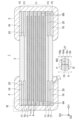
- FIG. 11 is a perspective view showing a capacitor according to a second embodiment. 1 is a table showing evaluation results of the capacitor according to the embodiment.
- FIG. 11 is a schematic cross-sectional view showing a portion of a capacitor according to a third embodiment.
- the corners may be chamfered with a curved surface or the like, as long as the above concept of shape is valid.
- a corner formed by two sides may be chamfered to a length of 1/5, 1/10, or 1/20 of the length of the shorter of the two sides.
- the corners may be rounded due to manufacturing precision (error). The same applies to other polygons, etc.
- Fig. 1 is a perspective view showing a capacitor 1 (an example of a multilayer electronic component) according to a first embodiment.
- a Cartesian coordinate system D1D2D3 is attached to Fig. 1 and other figures described later.
- the capacitor 1 may be used with either side being the upper or lower.
- the +D3 side may be regarded as the upper side, and terms such as the upper surface and the lower surface may be used.
- Capacitor 1 is, for example, a multilayer ceramic capacitor. Capacitor 1 has a roughly rectangular parallelepiped body 3 and four external electrodes 5 located at the four corners of body 3 in a plan view (as viewed in the D3 direction). The external electrodes 5 contribute to the electrical connection between capacitor 1 and other electronic components (for example, a circuit board not shown).
- FIG. 3 is a cross-sectional view taken along line III-III in FIG. 1.
- FIG. 3 shows a D1D3 cross-section taken through the external electrode 5 on the +D2 side.
- the D1D3 cross-section taken through the external electrode 5 on the -D2 side, the D2D3 cross-section taken through the external electrode 5 on the -D1 side, and the D2D3 cross-section taken through the external electrode 5 on the +D1 side are basically the same.
- the terms D1, D2, and D3 may be used to explain the positional relationships between the components, without any particular mention, assuming the cross-section shown in FIG. 3.
- the main body 3 has, for example, an effective portion 11, two covers 13 respectively overlapping the upper and lower surfaces of the effective portion 11, and an undercoat layer 15 overlapping the surface of each cover 13 opposite the effective portion 11.
- the effective portion 11 has a plurality of dielectric layers 7 and a plurality of internal electrodes 9 which are alternately overlapped.
- the multiple internal electrodes 9 include a plurality of first internal electrodes 9A and a plurality of second internal electrodes 9B.
- Each undercoat layer 15 has, for example, four undercoat electrodes 16 at positions corresponding to the positions of the four external electrodes 5.
- the external electrodes 5 overlap the undercoat electrodes 16.
- the active portion 11 directly functions as a capacitor.
- the cover 13 contributes, for example, to protecting the main body portion 3 and improving its strength.
- the base electrode 16 contributes, for example, to depositing the metal that will become the external electrode 5 by plating and/or improving the adhesive strength of the external electrode 5 to the main body portion 3.
- the lower part of Figure 3 shows an enlarged view of the boundary between the base electrode 16 and the external electrode 5.
- the material of the base electrode 16 e.g., a metal
- the material of the external electrode 5 e.g., a metal
- the external diffusion layer 5a and the base diffusion layer 16a form a diffusion layer 21.
- the base electrode 16 and the external electrode 5 share the diffusion layer 21 in which the material of the base electrode 16 and the material of the external electrode 5 are mixed together, and are thereby fixed to each other.
- the formation of the diffusion layer 21 increases the adhesion strength of the external electrode 5 to the base electrode 16. This in turn reduces the likelihood that the external electrode 5 will peel off from the main body 3. Note that in order to form the diffusion layer 21, it is necessary to heat the electrode at an appropriate temperature or higher; the diffusion layer 21 will not be formed simply by forming a film of a metal material on the base electrode 16.
- (1.1. Configuration of the Capacitor According to the First Embodiment) (1.1. Overall configuration) 1 is configured as, for example, a surface-mounted chip-type component. Specifically, for example, the capacitor 1 is placed with its -D3 side or +D3 side facing a circuit board (not shown). Then, the four pads of the circuit board and the four external electrodes 5 are respectively joined with a conductive bonding material (e.g., solder) (not shown), thereby mounting the capacitor on the circuit board.
- a conductive bonding material e.g., solder
- the configuration (internal structure and external shape) of capacitor 1 is, for example, roughly plane-symmetric with respect to a plane of symmetry (not shown) that is parallel to the D1D2 plane and passes through the center of capacitor 1 in the thickness direction (D3 direction).
- the configuration of capacitor 1 is, for example, rotationally symmetric by 180° when viewed in the D3 direction.
- capacitor 1 does not have to have such symmetry.
- the shape of the main body 3 is, for example, roughly a thin rectangular parallelepiped.
- This rectangular parallelepiped may be a square (as in the illustrated example) or a rectangle (excluding a square; the same applies below) in plan view.
- a square shape may be assumed unless otherwise specified.
- the specific dimensions of the main body 3 (or the capacitor 1) are arbitrary. As an example of dimensions when the capacitor 1 is relatively small, the lengths of the main body 3 (or the capacitor 1) in the D1 and D2 directions may each be 0.030 mm or more and 0.200 mm or less. When the length in the D1 direction is L and the length in the D2 direction is W, L/W may be 0.5 or more and 2.0 or less. The thickness in the D3 direction may be 0.030 mm or more and 0.200 mm or less. When the surface of the main body 3 is not flat, for example, the maximum values of the various dimensions may satisfy the above ranges (the same applies below to the various dimensions of the other components, unless a contradiction arises).
- the example dimensions of each component described below are for a relatively small capacitor 1. Therefore, dimensions larger (or smaller) than the example dimensions may be used.
- Multiple components of the same type may basically (except for relatively small differences, for example; the same applies below) be provided with the same (or corresponding) shape, size, material, position, etc., unless otherwise specified or unless a contradiction occurs. Therefore, unless otherwise specified or unless a contradiction occurs, a description of one component may be considered to be common to multiple components of the same type.
- a single layered (membrane-like) component may be entirely made of one type of material. However, it may also be made of layers made of different materials.
- the shape of the effective portion 11 shown in FIG. 3 is, for example, approximately a thin rectangular parallelepiped. Its planar shape is basically the same as that of the main body portion 3.
- the specific thickness of the effective portion 11 is arbitrary.
- the thickness of the effective portion 11 may be 30% or more, 40% or more, or 50% or more, or 90% or less, 80% or less, or 70% or less, relative to the thickness of the main body portion 3.
- the above lower limit and upper limit may be combined with any one of them.
- the thickness of the main body portion 3 is, for example, the thickness from the upper surface of the upper base electrode 16 to the lower surface of the lower base electrode 16.
- the thickness of the effective portion 11 is, for example, the thickness from the upper surface of the internal electrode 9 of the uppermost layer to the lower surface of the internal electrode 9 of the lowermost layer.
- the dielectric layer 7 is basically a layer having a constant thickness (at least between the internal electrodes 9).
- the thickness of the dielectric layer 7 may be set appropriately depending on the characteristics required of the capacitor 1.
- the thickness between adjacent internal electrodes 9 may be 0.1 ⁇ m or more or 0.5 ⁇ m or more, and may be 3.0 ⁇ m or less, 2.0 ⁇ m or less, or 1.0 ⁇ m or less.
- the above lower and upper limits may be combined with any combination.
- the shape and dimensions of the dielectric layer 7 in a planar view are basically the same as the shape and dimensions of the active part 11 in a planar view.
- the material of the dielectric layer is, for example, ceramics, and the specific type is also arbitrary.
- the number of layers of the dielectric layer 7 (internal electrodes 9) is arbitrary. One example is 10 layers or more and 30 layers or less.
- the internal electrode 9 is in the form of a layer having a certain thickness.
- the thickness of the internal electrode 9 is arbitrary, and may be thinner, the same as, or thicker than the thickness of the region of the dielectric layer 7 between the internal electrodes 9.
- the thickness of the internal electrode 9 may be 0.3 ⁇ m or more, or 0.5 ⁇ m or more, and may be 3.0 ⁇ m or less, 2.0 ⁇ m or less, or 1.0 ⁇ m or less.
- the above lower and upper limits may be combined in any way.
- the material of the internal electrode 9 is, for example, a metal.
- the specific type of metal is arbitrary.
- the entire or main component (for example, 60 mass% or more of the component; the same applies to other materials below) of the metal (or the material of the internal electrode 9) of the internal electrode 9 is a base metal (for example, Ni and/or Cu).
- the internal electrode 9 may contain ceramics in addition to the metal.
- This ceramic may be a common material (for convenience, the ceramics in the electrode will be referred to as the common material below) when the internal electrode 9 is formed by a conductive paste that is simultaneously fired with the ceramic green sheet that becomes the dielectric layer 7.
- the common material may be, for example, the same as the component (for example, the main component) contained in the dielectric layer 7.
- the common material may be barium titanate.
- the content of the common material in the internal electrode 9 (after firing) is arbitrary, and may be, for example, 1 mass% or more and 30 mass% or less.
- FIG. 2 is an exploded perspective view of the capacitor 1.
- FIG. 2 is a schematic diagram for understanding the shape and relative positions of the internal electrodes 9, etc. Therefore, FIG. 2 shows a smaller number of different layers than FIG. 3.
- the internal electrode 9 has, for example, a rectangular (square in the illustrated example) electrode body 9a in a plan view, and a pair of extraction electrodes 9b extending from a pair of opposing corners of the electrode body 9a.
- the internal electrode 9 is located inside the outer edge of the dielectric layer 7 and is not exposed from the side of the active portion 11.
- the pair of extraction electrodes 9b reach the outer edge of the dielectric layer 7 and are connected to a pair of external electrodes 5 located at a pair of opposing corners of the main body portion 3.
- the first internal electrode 9A and the second internal electrode 9B face each other with the dielectric layer 7 in between.
- a pair of extraction electrodes 9b of the first internal electrode 9A and a pair of extraction electrodes 9b of the second internal electrode 9B are located on different diagonals in a plan view. Both are connected to a pair of external electrodes 5 that are different from each other.
- the various dimensions of the electrode body 9a and the extraction electrode 9b are arbitrary.
- the length of one side of the dielectric layer 7 of the extraction electrode 9b (the length of one side of the edge) is approximately the same as the length along the above-mentioned one side of the external electrode 5.
- the cover 13 shown in FIG. 3 is, for example, a layer having a shape and dimensions that overlap the effective portion 11 without excess or deficiency.
- the thickness of the cover 13 is approximately constant in each of the arrangement region and non-arrangement region of the base electrode 16.
- the ratio of the thickness of the cover 13 to the thickness of the main body portion 3 may be approximately the reverse of the ratio of the thickness of the effective portion 11 to the thickness of the main body portion 3 (as described above).
- the thickness of one cover 13 may be, for example, 5% or more, 10% or more, or 15% or more of the thickness of the main body portion 3, and may be 35% or less, 30% or less, or 25% or less.
- the above lower limit and upper limit may be combined arbitrarily.
- the thickness of the cover 13 is, for example, the thickness in a region that overlaps the internal electrode 9 and does not overlap the base electrode 16 (not crushed by the base electrode 16).
- Each cover 13 has, for example, multiple (two in the example of FIG. 3) insulating layers 17 and at least one (one in the example of FIG. 3) dummy layer 19 located between the multiple insulating layers 17.
- Each dummy layer 19 has, for example, four dummy electrodes 20 at positions corresponding to the positions of the four external electrodes 5.
- the dummy electrodes 20 contribute, for example, to reinforcing the cover 13 and/or improving the connection strength between the main body 3 and the external electrodes 5, and also function as a base for the external electrodes 5 in an embodiment in which the external electrodes 5 are formed by plating.
- the cover 13 may have only one or more insulating layers 17 (it may not have a dummy layer 19).
- the insulating layers 17 and the dummy layers 19 are alternately stacked one on top of the other.
- the dummy layers 19 are provided at the boundaries of all the insulating layers 17.
- the dummy layers 19 may be provided only at some of the boundaries.
- the dummy layers 19 may not be provided at one or more boundaries that are relatively close to the active portion 11, and the dummy layers 19 may be provided only at one or more boundaries that are relatively far from the active portion 11.
- two or more insulating layers 17 that are in close contact with each other without a dummy layer 19 in between may be regarded as one insulating layer 17.
- the insulating layer 17 is a layer having a generally constant thickness, except for variations in thickness resulting from the presence or absence of overlap with the conductor layers (9, 15, and 19).
- the planar shape of the insulating layer 17 is, for example, basically the same as the planar shape of the dielectric layer 7.
- the material of the insulating layer 17 is arbitrary.
- the material of the insulating layer 17 may be the same as the material of the dielectric layer 7, or may be different.
- the material of the insulating layer 17 may be, for example, ceramics, or a material other than ceramics.
- the thickness of the insulating layer 17 is arbitrary.
- the thickness of the insulating layer 17 may be thicker (as in the illustrated example) than the thickness of the dielectric layer 7 (either the thickness between the conductor layers or the thickness of the area not overlapping the conductor layers. The same applies below in this paragraph).
- the thickness of the insulating layer 17 may be 2 times or more, 3 times or more, or 5 times or more, or 20 times or less, 10 times or less, or 5 times or less, of the thickness of the dielectric layer 7.
- the above lower limit and upper limit may be combined in any combination.
- the thickness of the insulating layer 17 may be 1.0 ⁇ m or more, or 2.0 ⁇ m or more, or 10.0 ⁇ m or less, or 5.0 ⁇ m or less.
- the above lower limit and upper limit may be combined in any combination.
- the insulating layer overlapping the uppermost internal electrode 9 may be regarded as the insulating layer 17, not the dielectric layer 7, regardless of its material and thickness. The same applies to the insulating layer overlapping the lowermost internal electrode 9.
- the dummy electrode 20 is, for example, a layer having a basically constant thickness.
- the material of the dummy electrode 20 is, for example, a metal.
- the specific type of metal is arbitrary.
- the entire or main component of the metal of the dummy electrode 20 (or the material of the dummy electrode 20) is a base metal (for example, Ni and/or Cu).
- the dummy electrode 20 may also contain ceramics, as with the internal electrode 9. The description of the ceramics in the internal electrode 9 may be applied to the ceramics in the dummy electrode 20 by replacing the terms internal electrode 9 and dielectric layer 7 with the terms dummy electrode 20 and insulating layer 17, respectively.
- the material of the dummy electrode 20 may be the same as or different from the material of the internal electrode 9.
- the position, shape, and dimensions of the dummy electrode 20 are arbitrary. In the example of Figs. 2 and 3, the position, shape, and dimensions of the dummy electrode 20 are such that, in a planar perspective view, it overlaps approximately exactly with the external electrode 5 (however, the external electrode 5 is slightly wider).
- the dummy electrode 20 is exposed, for example, on the side surface of the main body 3. This exposed portion is fixed to the external electrode 5.
- the thickness of the dummy electrode 20 is arbitrary.
- the thickness of the dummy electrode 20 may be thicker than the thickness of the internal electrode 9 (as shown in the example), may be approximately the same as the thickness of the internal electrode 9, or may be thinner.
- the thickness of the dummy electrode 20 may be 1 time or more, 1.5 times or more, or 2 times or more, or may be 10 times or less, 5 times or less, or 2 times or less, of the thickness of the internal electrode 9.
- the above lower limit and upper limit may be combined with any of them.
- the thickness of the dummy electrode 20 may be 0.3 ⁇ m or more, 0.5 ⁇ m or more, 1.0 ⁇ m or more, or 2.0 ⁇ m or more, or may be 10.0 ⁇ m or less, 5.0 ⁇ m or less, 3.0 ⁇ m or less, or 2.0 ⁇ m or less. The above lower limit and upper limit may be combined with any of them. Also, the thickness of the dummy electrode 20 may be thinner than the thickness of the insulating layer 17 (as shown in the example), may be equivalent to the thickness of the insulating layer 17, or may be thicker than the thickness of the insulating layer 17.
- the base electrode 16 is, for example, a layer having a basically constant thickness.
- the material of the base electrode 16 is, for example, a metal.
- the specific type of metal is arbitrary.
- the entire or main component of the metal of the base electrode 16 (or the material of the base electrode 16) is a base metal (for example, Ni and/or Cu).
- the base electrode 16 may also include ceramics, as with the internal electrode 9 and the dummy electrode 20.
- the description of the ceramics in the internal electrode 9 may be applied to the ceramics in the base electrode 16 by replacing the terms of the internal electrode 9 and the dielectric layer 7 with the terms of the base electrode 16 and the insulating layer 17, respectively.
- the material of the base electrode 16 may be the same as or different from the material of the internal electrode 9 and/or the material of the dummy electrode 20.
- the position, shape, and dimensions of the base electrode 16 are arbitrary. In the examples of Figures 2 and 3, the position, shape, and dimensions of the base electrode 16 are such that, in a plan view, they overlap approximately exactly with the external electrode 5 (however, the external electrode 5 is slightly wider).
- the thickness of the base electrode 16 is arbitrary.
- the thickness of the base electrode 16 may be thicker than the thickness of the internal electrode 9 and/or the dummy electrode 20 (example shown in the figure), may be approximately the same as the thickness of the internal electrode 9 and/or the dummy electrode 20, or may be thinner.
- the thickness of the base electrode 16 may be two or more times, three or more times, or five or more times the thickness of the internal electrode 9 and/or the dummy electrode 20, or may be 20 or less times, 10 or less times, or 5 or less times. The above lower limit and upper limit may be combined with any of them.
- the thickness of the base electrode 16 may be 2.0 ⁇ m or more, 3.0 ⁇ m or more, or 5.0 ⁇ m or more, or may be 20.0 ⁇ m or less, 10.0 ⁇ m or less, or 5.0 ⁇ m or less. The above lower limit and upper limit may be combined with any of them. Also, the thickness of the base electrode 16 may be thinner than the thickness of the insulating layer 17, may be the same as the thickness of the insulating layer 17, or may be thicker than the thickness of the insulating layer 17 (example shown in the figure).
- the external electrode 5 is, for example, a layer having a basically constant thickness.
- the material of the external electrode 5 is, for example, a metal.
- the specific type of metal is arbitrary.
- the entire or main component of the metal of the external electrode 5 (or the material of the external electrode 5) is a base metal (for example, Ni and/or Cu).
- the external electrode 5 may or may not contain a nonmetal (for example, ceramics). In the description of the embodiment, the latter is basically taken as an example.
- the external electrode 5 may be configured by laminating different materials from each other as necessary.
- the external electrode 5 may be configured by laminating Cu, Ni, and Sn from the side of the base electrode 16.
- the material of the external electrode 5, the material of the internal electrode 9, the material of the dummy electrode 20, and/or the material of the base electrode 16 may be the same as or different from the material of the external electrode 5. However, before diffusion bonding, the material of at least the layer of the external electrode 5 that is in contact with the base electrode 16 is different from the material of the layer of the base electrode 16 that is in contact with the external electrode 5.
- the external electrodes 5 cover the four faces (top, bottom and two side faces) of the main body 3, for example, roughly at the corners in a plan view of the main body 3. This allows one external electrode 5 to be connected to one extraction electrode 9b on the two side faces of the main body 3, and also makes it possible to surface mount the capacitor 1 on either the top or bottom face.
- the shape and dimensions of the portions on each face of the external electrode 5 are arbitrary.
- the planar shape of the portion of the external electrode 5 located on the top or bottom face of the main body 3 is, for example, rectangular (square in the illustrated example).
- the planar shape and dimensions of the portion of the external electrode 5 located on the side face of the main body 3 is, for example, rectangular with the same horizontal length as the portion located on the top or bottom face.
- the thickness of the external electrode 5 is arbitrary.
- the thickness of the external electrode 5 may be thicker than the thicknesses of the internal electrode 9, the dummy electrode 20, and the base electrode 16.
- the thickness of the external electrode 5 may be 1.2 times or more, 2 times or more, or 3 times or more, or 10 times or less, 5 times or less, or 3 times or less, of the thickness of the base electrode 16.
- the above lower limit and upper limit may be combined in any combination.
- the thickness of the external electrode 5 may be 3 ⁇ m or more, 5 ⁇ m or more, or 10 ⁇ m or more, or 30 ⁇ m or less, 20 ⁇ m or less, or 10 ⁇ m or less.
- the above lower limit and upper limit may be combined in any combination.
- the main component of the base electrode 16 (or a metal therein; the same applies below) is referred to as the first metal.
- the main component of the external electrode 5 is referred to as the second metal.
- the first metal and the second metal are different from each other.
- the first metal may be taken as an example of the material of the base electrode 16 that diffuses into the external electrode 5
- the second metal may be taken as an example of the material of the external electrode 5 that diffuses into the base electrode 16.
- the term “first metal” may be interchanged with the term "material of the base electrode 16”
- the term “second metal” may be interchanged with the term "material of the external electrode 5,” unless a contradiction or the like arises.
- the mass percentages shown below may be taken as values when ignoring the common materials (metals and nonmetals contained in the common materials) contained in the base electrode 16, unless a contradiction arises. However, unless a contradiction arises, the mass percentages may be taken as values when taking into account the common materials (or, from another perspective, all components of the base electrode 16). Also, exceptionally, the atomic percentages described below cover all atoms contained in the base electrode 16 or the external electrode 5. For example, the denominator (or numerator) of the atomic percentage in the base electrode 16 includes the amount of elements contained in the common materials.
- the portion of the base electrode 16 other than the base diffusion layer 16a is referred to as the base non-diffusion layer 16b.
- the portion of the external electrode 5 other than the external diffusion layer 5a is referred to as the external non-diffusion layer 5b.
- the boundary between the base electrode 16 and the external electrode 5 is referred to as the interface BS.
- the base non-diffusion layer 16b does not have to exist.
- the second metal of the external electrode 5 may diffuse throughout the entire thickness of the base electrode 16, so that the entire base electrode 16 becomes the base diffusion layer 16a. While the base non-diffusion layer 16b has been described above, the same is true for the external non-diffusion layer 5b.
- the external diffusion layer 5a and the external non-diffusion layer 5b are a single metal layer made of the same material.
- the external electrode 5 may be configured by stacking multiple metal layers before the above-mentioned diffusion.
- the above-mentioned single metal layer may be expressed as the external electrode 5 unless otherwise specified.
- the material of the other metal layer may diffuse into the external non-diffusion layer 5b.
- the explanation of such diffusion is omitted. Note that the explanation of the components of the external non-diffusion layer 5b in the following explanation may apply to aspects in which the above-mentioned diffusion has occurred and/or has not occurred, unless otherwise specified and unless there is any contradiction. Although the explanation has been given for the external electrode 5, the same applies to the base electrode 16.
- a component that is 60% by mass or more is referred to as a main component, and the main component of the base electrode 16 is referred to as a first metal.
- which component is 60% by mass or more may be determined, for example, based on the material of the base electrode 16 before diffusion occurs.
- it may be determined, for example, in a region of the thickness of the base electrode 16 where the second metal has not diffused. As will be understood from the explanation below, this region may be, for example, a region of the base non-diffusion layer 16b that is further away from the external electrode 5 than the base diffusion layer 16a.
- the base electrode 16 does not have an area in which the second metal does not diffuse as described above, it may be determined, for example, whether any component is 60 mass% or more in the area in which the amount of diffusion of the second metal (e.g., atomic %) is the smallest (or the area expected to be such).
- the area in which the second metal does not diffuse can also be considered as an example of an area in which the amount of diffusion of the second metal is the smallest.
- the second metal is not specified, for example, the area furthest from the external electrode 5 (the central area of the thickness of the base electrode 16 depending on the configuration of the side opposite the external electrode 5) may be used to determine the area expected to have the smallest amount of diffusion of the second metal.
- base electrode 16 before diffusion may be replaced with terms such as "the region of the base electrode 16 in which the amount of diffusion of the second metal is the smallest” unless a contradiction arises.
- external electrode 5 before diffusion may be replaced with terms such as "the region of the external electrode 5 in which the amount of diffusion of the first metal is the smallest” unless a contradiction arises.
- diffusion layer 21 includes the following first and second aspects.
- the base electrode 16 and the external electrode 5 before diffusion have different pure metals.
- the elements of the pure metals are a first metal and a second metal.
- the diffusion layer 21 is an alloy of the first metal and the second metal.
- the first metal (base electrode 16) is Ni
- the second metal (external electrode 5) is Cu
- the material of the diffusion layer 21 is a Ni-Cu alloy and/or a Cu-Ni alloy.
- the impurities may be metals and/or non-metals.
- the amount of these impurities may be taken into consideration when determining whether the requirements for the main component, such as 60 mass % or 12.5 atomic % described below, are met. Impurities that are not pure metals are treated in the same way.
- the base electrode 16 and the external electrode 5 before diffusion contains an alloy.
- the main components (first metal and second metal) of the material of the base electrode 16 and the material of the external electrode 5 are different from each other.
- the diffusion layer 21 is an alloy containing both main components.
- the base electrode 16 is made of a Ni alloy (the first metal is Ni)
- the external electrode 5 is made of a Cu alloy (the second metal is Cu)
- the material of the diffusion layer 21 is a Ni-Cu alloy and/or a Cu-Ni alloy.
- examples of the minor components (e.g., components of 40 mass% or less) contained in the Ni alloy (metal constituting the base electrode 16 before diffusion) include Cr, Mo, Fe, Co, and Cu.
- examples of the minor components contained in the Cu alloy (metal constituting the external electrode 5 before diffusion) include Sn, Zn, Pb, Fe, Mn, Al, Be, W, and Ni.
- the base electrode 16 before diffusion may contain the main component of the external electrode 5 before diffusion (second metal: e.g., Cu) as a secondary component.
- second metal e.g., Cu
- the presence of the base diffusion layer 16a can be identified when the amount of the second metal contained as a secondary component in the base electrode 16 before diffusion is less than 12.5 atomic %.
- the secondary components of the base electrode 16 have been described above, the same applies to the secondary components of the external electrode 5.
- the main components (each of the first metal and the second metal) have, for example, one type of element and/or one type of element is regarded as the main component.
- two or more elements may be the main components and/or two or more elements may be regarded as the main components.
- the base electrode 16 before diffusion is Ni (pure metal)
- the external electrode 5 before diffusion is a Cu-Al alloy.
- the requirement of 60 mass% or more may be satisfied by Cu alone, or the requirement of 60 mass% or more may be satisfied by the total of Cu and Al.
- only Cu may be regarded as the main component of the external electrode 5, or both Cu and Al may be regarded as the main components.
- the state of the alloy in the diffusion layer 21 is arbitrary.
- the alloy may be mainly a solid solution, a eutectic, or an intermetallic compound.
- Ni-Cu alloys or Cu-Ni alloys are usually solid solutions.
- grain boundary diffusion and/or volume diffusion may occur in the diffusion layer 21.
- the thickness t1 of the base diffusion layer 16a and the thickness t2 of the external diffusion layer 5a are arbitrary.
- the thickness t1 may be 1.0 ⁇ m or more and 3.5 ⁇ m or less, and/or 0.25 to 0.88 with respect to the thickness of the base electrode 16.
- the thickness t2 may be 1.0 ⁇ m or more and 3.5 ⁇ m or less, and/or 0.10 to 0.58 with respect to the thickness of the external electrode 5.
- the thickness t1 and the thickness t2 may be the same or different from each other. In the latter case, the degree of difference is also arbitrary.
- the thickness t1 may be 2/3 to 3/2 or 6/7 to 7/6 of the thickness t2. Note that in the examples described later, it is shown that the fixing force of the external electrode 5 is secured to a certain degree in the case of the above-mentioned thicknesses.
- the boundary line on the opposite side of the base diffusion layer 16a from the external electrode 5 (the boundary line between the base diffusion layer 16a and the base non-diffusion layer 16b) for specifying the thickness t1 may be, for example, a position where the second metal is 12.5 atomic %.
- the base diffusion layer 16a may be a region that contains 12.5 atomic % or more of the second metal.
- the value of 12.5 atomic % is the value used when determining thickness t1 and thickness t2 in the examples described below.
- the diffusion layer is defined using the value of 12.5 atomic % for the convenience of determining thickness t1 and/or thickness t2.
- the above definition may be used as necessary.
- the boundary line between the underlying diffusion layer 16a and the underlying non-diffusion layer 16b may be specified with the accuracy required to obtain the thickness of the diffusion layer 21, for example.
- the boundary line since the range of thicknesses t1 and t2 exemplified in this disclosure (described above) has a significant digit of 0.1 ⁇ m, the boundary line may be specified with an accuracy of 0.1 ⁇ m (or with an even higher accuracy).
- the atomic percentage may be calculated, for example, in a unit area in which the boundary line can be specified with the above-mentioned accuracy.
- the unit area may be, for example, 0.01 ⁇ m 2 (or with an even smaller area).
- the shape of each unit area may be, for example, a square (for example, a square of 0.1 ⁇ m ⁇ 0.1 ⁇ m).
- the boundary line where the diffusion amount is 12.5 atomic % is not necessarily a straight line, but may have undulations (wavy shape). In cases where undulations affect the determination of whether thicknesses t1 and/or t2 are within the ranges exemplified in the embodiments, thicknesses t1 and t2 may be determined based on, for example, the average height of the boundary line. The average height is also used in the examples described below.
- the base electrodes 16 are located at the four corners of each of the upper and lower surfaces of the main body 3, and a total of eight base electrodes 16 are provided.
- the above-mentioned range of thickness t1 and/or thickness t2 does not need to be true for all of the multiple (eight) base electrodes 16.
- the above-mentioned thickness range may be satisfied for only one base electrode 16.
- the above-mentioned thickness range may be satisfied for all of the base electrodes 16.
- the above thickness range does not have to be satisfied over the entire base electrode 16. For example, it may be satisfied only over 50% or 80% or more of the area of the base electrode 16. Of course, the above thickness range may be satisfied over the entire base electrode 16. However, even in this case, the unique portion may be excluded.
- An example of the unique portion is the edge of the base electrode 16. Since the edge is covered by the external electrode 5 not only on the top surface but also on the side surface, a diffusion layer 21 is basically formed over the entire thickness.
- each base electrode 16 may be determined based on a predetermined number (e.g., 3, 5, or 10) of D1D3 cross-sectional images set at equal distances along the length of the base electrode 16 in the D2 direction. If it is difficult to extract multiple cross-sectional images from one capacitor 1, multiple cross-sectional images may be extracted from multiple capacitors 1 of the same type.
- a predetermined number e.g. 3, 5, or 10
- the cross-sectional image may be obtained at an appropriate magnification, for example, by a scanning electron microscope (SEM).
- SEM scanning electron microscope
- the SEM may have a function for displaying areas in the image in different colors according to the atomic percentage of a particular element. Using this function, areas in which the first metal or the second metal is 12.5 atomic % or more may be identified and their dimensions measured.
- the interface BS can be observed in the SEM image. This is due to the presence of a cavity between the two and/or the difference in the size of the crystal grains of the two.
- the interface BS may be identified with the accuracy required for calculating (determining) the thickness t1 and/or the thickness t2, as with the 12.5% atomic boundary line, and the average height may be identified as necessary.
- the interface BS does not have to be observable when the thicknesses t1 and/or t2 are not measured.
- the capacitor 1 may be manufactured by various methods.
- the outline of the manufacturing process may be the same as a known process. An example is shown below.
- ceramic green sheets that will become the dielectric layer 7 and insulating layer 17 are prepared.
- a conductive paste that will become the internal electrode 9, dummy electrode 20, or base electrode 16 is applied (e.g., printed) to the ceramic green sheets.
- the ceramic green sheets are stacked to prepare a laminate that will become the main body portion 3. Note that the stacking of the laminate that will become the active portion 11 and the stacking of the portion that will become the cover 13 for the laminate may be performed together or separately.
- the above-mentioned process up to the creation of the laminate is carried out, for example, on a mother board the size of which a large number of main body parts 3 are to be cut.
- the mother board including the laminate is diced (e.g. cut) into pieces of a size roughly corresponding to the size of the main body parts 3.
- the laminate having the size of the main body parts 3 is fired. After that, a metal film is formed on the main body parts 3, and the external electrodes 5 are formed.
- Degreasing may be performed before firing. Firing may be performed, for example, in a reducing atmosphere. Reoxidation heat treatment may be performed after firing. Polishing (e.g., barrel polishing) of the main body portion 3 may be performed before and/or after firing. In polishing, for example, the ridges of the main body portion 3 may be chamfered or the sides of the main body portion 3 may be polished.
- the external electrode 5 may be formed by various methods. For example, metal may be deposited on the surface of the base electrode 16 and the edge of the internal electrode 9 by electroless plating and/or electrolytic plating. Also, thin film formation methods such as dipping, printing, CVD (Chemical Vapor Deposition) or PVD (Physical Vapor Deposition) may be employed. As will be understood from the above, the base electrode 16 may or may not contribute to the deposition of metal.
- the external electrode 5 and the base electrode 16 are heated while pressure is applied to them.
- the specific method is arbitrary.
- a heater may be pressed against the external electrode 5, or the capacitor 1 may be placed in a furnace together with a tool that presses the external electrode 5 against the base electrode 16.
- the process for forming the diffusion layer 21 may also be combined with other processes (e.g., annealing).
- the temperature during heating may be set appropriately depending on the specific types of the first metal and the second metal. For example, in the case of Ni and Cu, heating may be performed so that these temperatures reach 450°C or higher or 600°C or higher. However, the temperature at this time is, for example, below the solidus.
- the specific magnitude of the pressure is also arbitrary.
- the thickness of the diffusion layer 21 can be adjusted, for example, by controlling the heating temperature, heating time, and number of heating times.
- Fig. 4 is a perspective view of a capacitor 201 according to a second embodiment.
- Fig. 3 according to the first embodiment may be referred to as a cross-sectional view of the capacitor 201.
- capacitor 201 differs from capacitor 1, which is a four-terminal type, in that it is a two-terminal type.
- a diffusion layer 21 may be configured as described with reference to FIG. 3.
- each part of capacitor 201 may differ from those of capacitor 1, since it is a two-terminal type. Specifically, they are as follows:
- the shape of the main body 203 is, for example, roughly rectangular.
- the height (length in the D3 direction) of this rectangular parallelepiped may be equal to (as in the illustrated example) or smaller than the width (length in the D2 direction).
- the length (D1 direction) of the rectangular parallelepiped is, for example, greater than the width.
- the dimensions of the main body 203 are arbitrary. As long as the length in the D1 direction is greater than the length in the D2 direction, the specific example dimensions of the main body 3 in the first embodiment may be applied to the dimensions of the main body 203.
- the external electrode 5 is roughly layered, covering the longitudinal ends of the main body 203 across the five faces of the rectangular parallelepiped.
- the planar shape of the internal electrode 9 is, for example, roughly a rectangle with four sides parallel to the four sides of the rectangular main body 203 (dielectric layer 7). Of the four sides of the internal electrode 9, two long sides and one short side are, for example, located inside the side of the main body 203 (not exposed). The remaining short side is exposed from the side of the +D1 or -D1 side of the main body 203.
- the area of the internal electrode 9 that overlaps with other internal electrodes 9 in a planar perspective is the electrode body 9a.
- the portion extending from the electrode body 9a to the external electrode 5 is the extraction electrode 9b.
- Each dummy layer 19 has, for example, two dummy electrodes 20 at both ends of the longitudinal direction of the main body 203.
- the planar shape of the dummy electrodes 20 is, for example, a rectangle that spans the entire width (length in the D2 direction) of the main body 203, and is exposed, for example, from the side surface on the +D1 side or -D1 side of the main body 203, and from the side surface on the +D2 side and the -D2 side.
- the above description of the configuration of the dummy layer 19 (dummy electrodes 20) in a planar view may be used for the configuration of the base layer 15 (base electrode 16) in a planar view.
- the capacitor may have an exterior resin that covers the entire structure illustrated in FIG. 1 or FIG. 4, and a lead wire that is connected to the external electrode 5 and extends from the exterior resin.
- the capacitor may be a through-hole mount type rather than a surface mount type.
- one external electrode 5 may only cover one side surface.
- Two types of internal electrodes 9 connected to different external electrodes 5 may be alternately stacked two at a time, rather than one at a time.
- the thickness of the dielectric layer 7 between the internal electrodes 9 that are connected to the same external electrode 5 and face each other may be thinner than the thickness of the dielectric layer 7 between the internal electrodes 9 that are connected to different external electrodes 5 and face each other.
- the multiple dielectric layers 7 do not have to have the same shape and size.
- the two types of internal electrodes 9 connected to different external electrodes 5 do not have to face each other.
- two types of internal electrodes 9 connected to different external electrodes 5 may be provided in the same layer, and an internal electrode 9 facing the two types of internal electrodes 9 may be provided, thereby forming a circuit in which two parallel plate capacitors are connected in series.
- a circuit in which three or more parallel plate capacitors are connected in series may be formed.
- the edge of the internal electrode 9, for example, any portion other than the -D1 side or +D1 side is not exposed from the side of the main body 203.
- This non-exposed edge is covered by the portions of the dielectric layer 7 and the insulating layer 17 that extend further outward than the non-exposed edge.
- the non-exposed edge may be covered by overlapping another dielectric layer on the side of the laminate formed by the dielectric layer 7 and the insulating layer 17, thereby preventing it from being exposed. From another perspective, the entire main body 203 does not need to be a laminated structure.
- FIG. 6 is a schematic cross-sectional view showing a part of a capacitor 301 according to the third embodiment, which corresponds to region VI in FIG.
- diffusion also occurs between the internal electrode 9 and the external electrode 5. Diffusion also occurs between the dummy electrode 20 and the external electrode 5. Only the former diffusion or the latter diffusion may occur.
- the third embodiment may be applied to any of the embodiments described so far. The above explanation of the diffusion between the base electrode 16 and the external electrode 5 (explanation in Section 2, etc.) may be applied to the diffusion related to the internal electrode 9 and the diffusion related to the dummy electrode 20, for example, by replacing the term base electrode 16 with the term internal electrode 9 or dummy electrode 20, as long as no contradiction occurs.
- the extraction electrode 9b of the internal electrode 9 (in other words, the edge of the internal electrode 9) and the inner surface of the external electrode 5 are in contact with each other.
- the internal electrode 9 and the external electrode 5 are fixed by sharing a diffusion portion in which the materials of both electrodes are mixed.
- the diffusion portion extends along the edge of the internal electrode 9.
- FIG. 6 of the above-mentioned diffusion portions only the internal diffusion portion 9c formed by the material of the external electrode 5 diffusing into the material of the internal electrode 9 is shown.
- the external diffusion portion formed by the material of the internal electrode 9 diffusing into the material of the external electrode 5 is not shown. Note that the area of contact between the internal electrode 9 and the external electrode 5 is small. Therefore, the external diffusion portion does not need to be actually formed, and may be so small that it is difficult to observe.
- the above explanation may be applied to the diffusion between the dummy electrode 20 and the external electrode 5 by replacing the term internal electrode 9 with the term dummy electrode 20 and the term internal diffusion portion 9c with the term dummy diffusion portion 20c, as long as no contradictions arise.
- the materials of the internal electrode 9, the dummy electrode 20, and the base electrode 16 may be the same as or different from each other. This also applies to the case where diffusion between the internal electrode 9 and the external electrode 5 and/or diffusion between the dummy electrode 20 and the external electrode 5 occurs.
- the internal electrode 9, the dummy electrode 20, and the base electrode 16 may be made of Ni or an alloy mainly composed of Ni
- the external electrode 5 may be made of Cu or an alloy mainly composed of Cu.
- the length Li of the internal diffusion portion 9c from the edge of the internal electrode 9 is arbitrary.
- the length Ld of the dummy diffusion portion 20c from the edge of the dummy electrode 20 is arbitrary.
- at least one of Li ⁇ t1, t1 ⁇ Ld, and Li ⁇ Ld may be true, or all of them may not be true.
- Li ⁇ t1 ⁇ Ld may be true (example shown).
- t1 may be 1.05 or more, 1.10 or more, or 1.50 or more of Li, and may be 7.00 or less, 6.00 or less, or 5.00 or less, and the above lower limit and upper limit may be combined with any of them.
- Ld may be 1.05 or more, 1.10 or more, or 1.50 or more of t1, and may be 5.00 or less, 3.00 or less, or 2.00 or less, and the above lower limit and upper limit may be combined with any of them.
- Ld may be 1.10 or more, 1.20 or more, or 1.50 or more of Li, and may be 12.00 or less, 10.00 or less, or 5.00 or less, and the above lower limit and upper limit may be combined with any of them.
- t1 may be 0.30 ⁇ m or more and 6.00 ⁇ m or less.
- Li may be 0.20 ⁇ m or more and 5.90 ⁇ m or less (provided that Li ⁇ t1).
- Ld may be 1.00 ⁇ m or more and 7.00 ⁇ m or less (provided that Ld>Li and/or Ld>t1).
- the difference between Li and t1 may be 0.10 ⁇ m or more or 0.30 ⁇ m or more.
- the difference between t1 and Ld may be 0.10 ⁇ m or more or 0.30 ⁇ m or more.
- the difference between Li and Ld may be 0.20 ⁇ m or more or 0.4 ⁇ m or more.
- the above conditions of relative relationship and/or dimensions, etc. may be satisfied for only one external electrode 5, or may be satisfied for two or more (e.g., all or more than 50%) of the external electrodes 5. Furthermore, when focusing on each external electrode 5, the above conditions may be satisfied for only one base electrode 16, one internal electrode 9, and/or one dummy electrode 20 joined to that one external electrode 5, or may be satisfied for two or more (e.g., all or more than 50%) of each electrode (16, 9, or 20). In the latter case, the actual values of each electrode may satisfy the above conditions, or the average values may satisfy the above conditions.
- the average value of the lengths Li of 10 or more internal electrodes 9 and/or 30% or more (or 60% or more) of the total number of internal electrodes 9 may be used.
- the average value of the lengths Ld of two or more dummy electrodes 20 may be compared with the thickness t1 (or the average value of the lengths Li).
- the above-mentioned conditions concerning the relative relationship and/or dimensions of Li, t1, and Ld do not have to be satisfied over the entire length of the edge (contacting the external electrode 5) of the internal electrode 9 and/or dummy electrode 20.
- the conditions may be satisfied only over 50% or 80% of the length of a specific edge (one or two sides) of the internal electrode 9 (or dummy electrode 20) that contacts the external electrode 5.
- Whether or not the above conditions are satisfied over a certain length or more may be determined based on images of a predetermined number (e.g., 3, 5, or 10) of cross sections (e.g., D1D3 cross sections) set at equal distances from the edge. If it is difficult to extract images of multiple cross sections from one capacitor 1, images of multiple cross sections may be extracted from multiple capacitors 1 of the same type.
- the length Li may be obtained from an image showing a cross section as shown in FIG. 6 obtained by SEM or the like.
- the cross section may be, for example, along a direction (cutting direction, for example, D1 direction) perpendicular to the edge of the internal electrode 9 (for example, extending in the D2 direction and contacting the external electrode 5) in a plan view (for example, D1D3 cross section), or may be appropriately separated from the edge (singular part) of the internal electrode 9 along the cutting direction (for example, a cross section crossing the center position of the edge extending in the D2 direction).
- the range in which the main component (second metal) of the external electrode 5 is 12.5 atomic % or more may be specified as the internal diffusion portion 9c, and the length Li may be measured. If there is variation in the length Li in the thickness direction of the internal electrode 9, for example, the maximum value may be used for comparison with the thickness t1, etc.
- Li, t1, and Ld may be obtained from the same multiple cross-sectional images (or one cross-sectional image depending on the situation).
- a comparison may be made between individual cross-sections to determine whether the above conditions are satisfied in multiple cross-sections (e.g., 60% or more), or the average values of each dimension (Li, t1, or Ld) in multiple cross-sections may be compared to determine whether the above conditions are satisfied.
- the thickness t1 measured in each cross-section and compared with Li and/or Ld may be an average value excluding singular parts (e.g., edges).
- the average value of thickness t1 may be the average value over a length that is 30% or more, 50% or more, or 80% or more of the total length of the base electrode 16 in the D1 direction.
- any manufacturing method can be used to realize the above conditions related to the relative relationship and/or dimensions of Li, t1, and Ld.
- the above conditions can be realized by adjusting the particle size of the metal particles (e.g., Ni particles) contained in the conductive paste that becomes the base electrode 16, the internal electrode 9, and/or the dummy electrode 20.
- the particle size while taking into account the temperature of each electrode in the heat treatment, any Li, t1, and Ld can be realized.
- the above conditions were realized by setting the particle size of the Ni particles contained in the conductive paste that becomes the internal electrode 9, the base electrode 16, and the dummy electrode 20 to 150 nm to 200 nm, 350 nm to 400 nm, and 350 nm to 400 nm, respectively.
- Examples A prototype of the capacitor 1 according to the embodiment was produced and the adhesive strength of the external electrodes 5 was evaluated. As a result, it was confirmed that the diffusion layer 21 provided a capacitor 1 with a high adhesive strength of the external electrodes 5. Specifically, the following is true.
- FIG. 5 is a diagram showing the specifications of the capacitor 1 according to the embodiment.
- No. indicates the type of capacitor according to the embodiment.
- Examples E1 to E7 differ from each other in the configuration (thickness t1 and/or thickness t2) of the diffusion layer 21.
- t1 ( ⁇ m) and t2 ( ⁇ m)” columns indicate the values of thickness t1 and t2 in each example.
- thickness t1 and thickness t2 are each set in the range of 0.9 ⁇ m to 3.5 ⁇ m.
- t1 t2.
- t1 t2.
- t1 t2.
- t2 t1 ⁇ t2.
- t1 > t2.
- the "Qual.” column shows the evaluation results of the quality of the capacitor 1 according to the embodiment. Specifically, 100 samples were produced for each of the embodiments E1 to E7, and the presence or absence of peeling of the external electrode 5 from the base electrode 16 was checked. In the above column, the number of samples in which peeling occurred is shown as the numerator of the fraction.
- the material of the base electrode 16 was Ni.
- the material of the external electrode 5 was Cu.
- the thickness of the base electrode 16 was within a range of 2 ⁇ m to 4 ⁇ m (design value: 3 ⁇ m).
- the thickness of the external electrode 5 was within a range of 2 ⁇ m to 10 ⁇ m (design value: 6 ⁇ m).
- the thicknesses t1 and t2 were measured based on images obtained by SEM, as described above.
- Example E7 which has the thinnest thicknesses t1 and t2
- peeling occurred in two samples, but in the other Examples E1 to E6, no peeling occurred in any of the 100 samples.
- no samples were produced that did not have the diffusion layer 21, it can be inferred from the above results that the formation of the diffusion layer 21 reduces the likelihood of the external electrode 5 peeling off.
- Example E7 where peeling occurred, thickness t1 and thickness t2 were each 0.9 ⁇ m. In Examples E1 to E6, where peeling did not occur, thickness t1 and thickness t2 were each 1.0 ⁇ m or more. Therefore, it can be seen that by making thickness t1 and thickness t2 each 1.0 ⁇ m or more, a certain level of adhesive strength can be obtained.
- the minimum value of thickness t1 (1.0 ⁇ m) in Examples E1 to E6 is divided by an appropriate value (e.g., 2.0 ⁇ m, 3.0 ⁇ m, or 4.0 ⁇ m) selected from the range of thicknesses of the base electrode 16 of the samples to normalize the result to 0.50, 0.33, or 0.25 (rounded off to the nearest tenth; the same applies below).
- the maximum value of thickness t1 (3.5 ⁇ m) in Examples E1 to E6 is divided by an appropriate value (e.g., 3.5 ⁇ m or 4.0 ⁇ m) selected from the range of thicknesses of the base electrode 16 of the samples to normalize the result to 1.00 or 0.88.
- the range of thickness t1 may be determined by the lower limit and/or upper limit determined in this manner. An example of this has already been described.
- the minimum value of thickness t2 in Examples E1 to E6 (1.0 ⁇ m) is divided by an appropriate value selected from the range of thicknesses of the external electrode 5 of the sample (e.g., 2.0 ⁇ m, 6.0 ⁇ m, or 10.0 ⁇ m) to normalize the result to 0.50, 0.17, or 0.10.
- the maximum value of thickness t2 in Examples E1 to E6 (3.5 ⁇ m) is divided by an appropriate value selected from the range of thicknesses of the base electrode 16 of the sample (e.g., 3.5 ⁇ m, 6 ⁇ m, or 10 ⁇ m) to normalize the result to 1.00, 0.58, or 0.35.
- the range of thickness t2 may be determined by the lower limit and/or upper limit thus determined. An example of this has already been described.
- the multilayer electronic component has an active part 11, a cover 13, a base electrode 16, and an external electrode 5.
- the active part 11 has dielectric layers 7 and internal electrodes 9 that are alternately stacked in the stacking direction (D3 direction).
- the cover 13 on the +D3 side overlaps the active part 11 from the +D3 side of the first side (e.g., the +D3 side) and second side (e.g., the -D3 side) in the D3 direction.
- the base electrode 16 on the +D3 side overlaps the cover 13 from the +D3 side.
- the external electrode 5 on the +D3 side overlaps the base electrode 16 on the +D3 side from the +D3 side.
- the base electrode 16 and the external electrode 5 may be fixed by sharing a diffusion layer 21 in which the material of the base electrode 16 and the material of the external electrode 5 are mixed together.
- the adhesive strength of the external electrode 5 to the base electrode 16 can be increased.
- the probability of producing a defective product in which the external electrode 5 is peeled off from the base electrode 16 is reduced, and productivity is improved.
- the edge of the internal electrode 9 and the external electrode 5 may be in contact.
- the thickness t1 of the portion of the external electrode 5 where the material is diffused into the base electrode 16 at 12.5 atomic % or more may be greater than the length Li from the edge of the internal electrode 9 to the portion (internal diffusion portion 9c) where the material of the external electrode 5 is diffused into the internal electrode 9 at 12.5 atomic % or more.
- the thickness t1 is relatively large, which improves the effect of increasing the adhesive force described above.
- the length Li is relatively short, which reduces the likelihood of the internal electrode 9 expanding due to diffusion. As a result, for example, the likelihood of peeling between the internal electrode 9 and the dielectric layer 7 is reduced. In addition, for example, the likelihood of the characteristics of the capacitor 301 deteriorating due to the expansion (and even peeling) of the internal electrode 9 is reduced.
- the cover 13 may have two or more insulating layers 17 stacked in the D3 direction, and a dummy electrode 20 located at the boundary between the two or more insulating layers 17.
- the edge of the dummy electrode 20 may be in contact with the external electrode 5.
- the thickness t1 of the portion of the external electrode 5 material that is diffused into the base electrode 16 at 12.5 atomic % or more may be smaller than the length Ld from the edge of the dummy electrode 20 to the portion (dummy diffusion portion 20c) of the external electrode 5 material that is diffused into the dummy electrode 20 at 12.5 atomic % or more.
- the adhesive strength between the dummy electrode 20 and the external electrode 5 can be increased.
- the dummy electrode 20 is not a part that directly affects the characteristics of the capacitor 1, and therefore, when the length Ld is increased, unlike when the length Li is increased, the likelihood of the characteristics of the capacitor 1 deteriorating is low.
- the contact area between the dummy electrode 20 and the external electrode 5 is usually smaller than the contact area between the base electrode 16 and the external electrode 5. Therefore, by making Ld>t1, it is easier to improve the overall adhesive strength of the external electrode 5 to the cover 13.
- the edge (first edge) of the internal electrode 9 and the external electrode 5 may be in contact, and the edge (second edge) of the dummy electrode 20 and the external electrode 5 may be in contact.
- the length Li may be shorter than the length Ld.
- the adhesive strength between the dummy electrode 20 and the external electrode 5 can be increased.
- the likelihood of expansion (and even peeling) of the internal electrode 9 due to diffusion is reduced.
- the thickness t1 of the portion of the material (and/or second metal) of the external electrode 5 that is diffused into the base electrode 16 at 12.5 atomic % or more may be 1.0 ⁇ m or more and 3.5 ⁇ m or less. From another perspective, the thickness t1 may be 0.25 to 0.88 times the thickness of the base electrode 16.
- the adhesive force of the external electrode 5 to the base electrode 16 can be made to be equal to or greater than a certain level, as explained in the examples. If thickness t1 becomes too large, the volume of the base diffusion layer 16a generally increases, although this depends on the types of the first metal and second metal, for example. As a result, for example, stress is generated between the base diffusion layer 16a and other layers (for example, the insulating layer 17 and/or the base non-diffusion layer 16b), causing cracks. By making thickness t1 3.5 ⁇ m or less and/or 0.88 or less, for example, the likelihood of the above-mentioned cracks occurring can be reduced.
- the thickness t2 of the material (and/or first metal) of the base electrode 16 diffused into the external electrode 5 at 12.5 atomic % or more may be 1.0 ⁇ m or more and 3.5 ⁇ m or less. From another perspective, the thickness t2 may be 0.10 to 0.58 times the thickness of the external electrode 5.
- the adhesive strength of the external electrode 5 to the base electrode 16 can be made to be equal to or greater than a certain level, as explained in the examples.
- voids are generated, depending on the conditions. If thickness t2 is too large, the proportion of the total volume of the voids in the volume of the external electrode 5 increases. As a result, for example, the electrical resistivity of the external electrode 5 increases, and the electrical characteristics of the capacitor 1 deteriorate.
- thickness t2 3.5 ⁇ m or less and/or 0.58 or less for example, the deterioration of the electrical characteristics as described above can be reduced.
- Thickness t2 may be 2/3 or more and 3/2 or less of thickness t1.
- thickness t1 may be 2/3 or more and 3/2 or less of thickness t2.
- the diffusion layer 21 is biased toward one of the base electrode 16 and the external electrode 5, and as a result, the likelihood that the thickness t1 or thickness t2 will be thicker than the overall thickness (t1 + t2) of the diffusion layer 21 is reduced. In turn, the likelihood that the above-mentioned inconveniences will occur due to the thickness t1 or thickness t2 being too thick is reduced. From another perspective, the thickness of the diffusion layer 21 can be increased while reducing the likelihood that the thickness t1 or thickness t2 will be too thick, thereby increasing the adhesion strength.
- the base electrode 16 may be mainly composed of a first metal at least in a region away from the external electrode 5.
- the external electrode 5 may be mainly composed of a second metal different from the first metal at least in a region away from the base electrode 16.
- the first metal may be diffused into the external electrode 5, and the second metal may be diffused into the base electrode 16.
- the diffusion layer 21 may contain 12.5 atomic % or more of the first metal per area of 0.01 ⁇ m2 in a cross section parallel to the D3 direction, and may contain 12.5 atomic % or more of the first metal.
- the multilayer electronic component is not limited to a capacitor.
- some of the multiple internal electrodes may form a capacitor, and other parts of the multiple internal electrodes may form an inductor or resistor.
- the multilayer electronic component may form an appropriate circuit (for example, a resonant circuit) as a whole.
- the cover, base electrode, and external electrode may be provided on only one of the upper and lower surfaces of the active part.
- the external electrode 5 does not have to be in contact with the internal electrode 9 and/or the dummy electrode 20.
- the base electrode 16 may cover the end face of the cover 13 and be in contact with the dummy electrode 20, or may cover the end face of the active portion 11 and be in contact with the internal electrode 9.
Landscapes
- Engineering & Computer Science (AREA)
- Power Engineering (AREA)
- Manufacturing & Machinery (AREA)
- Microelectronics & Electronic Packaging (AREA)
- Chemical & Material Sciences (AREA)
- Ceramic Engineering (AREA)
- Inorganic Chemistry (AREA)
- Fixed Capacitors And Capacitor Manufacturing Machines (AREA)
- Ceramic Capacitors (AREA)
Priority Applications (2)
| Application Number | Priority Date | Filing Date | Title |
|---|---|---|---|
| JP2024568798A JPWO2025115525A1 (https=) | 2023-12-01 | 2024-11-05 | |
| US19/223,152 US12603230B2 (en) | 2023-12-01 | 2025-05-30 | Multilayer electronic component |
Applications Claiming Priority (2)
| Application Number | Priority Date | Filing Date | Title |
|---|---|---|---|
| JP2023-203881 | 2023-12-01 | ||
| JP2023203881 | 2023-12-01 |
Related Child Applications (1)
| Application Number | Title | Priority Date | Filing Date |
|---|---|---|---|
| US19/223,152 Continuation US12603230B2 (en) | 2023-12-01 | 2025-05-30 | Multilayer electronic component |
Publications (1)
| Publication Number | Publication Date |
|---|---|
| WO2025115525A1 true WO2025115525A1 (ja) | 2025-06-05 |
Family
ID=95896772
Family Applications (1)
| Application Number | Title | Priority Date | Filing Date |
|---|---|---|---|
| PCT/JP2024/039196 Pending WO2025115525A1 (ja) | 2023-12-01 | 2024-11-05 | 積層型電子部品 |
Country Status (4)
| Country | Link |
|---|---|
| US (1) | US12603230B2 (https=) |
| JP (1) | JPWO2025115525A1 (https=) |
| TW (1) | TW202526997A (https=) |
| WO (1) | WO2025115525A1 (https=) |
Citations (6)
| Publication number | Priority date | Publication date | Assignee | Title |
|---|---|---|---|---|
| JP2012009813A (ja) * | 2010-05-27 | 2012-01-12 | Murata Mfg Co Ltd | セラミック電子部品及びその製造方法 |
| JP2017022365A (ja) * | 2015-07-14 | 2017-01-26 | 株式会社村田製作所 | 積層セラミックコンデンサ |
| JP2017027987A (ja) * | 2015-07-16 | 2017-02-02 | 株式会社村田製作所 | 積層セラミックコンデンサ及び積層セラミックコンデンサの製造方法 |
| JP2020167231A (ja) * | 2019-03-28 | 2020-10-08 | 株式会社村田製作所 | 積層セラミックコンデンサおよび積層セラミックコンデンサの製造方法 |
| WO2023085264A1 (ja) * | 2021-11-10 | 2023-05-19 | 株式会社村田製作所 | 積層セラミックコンデンサ及びバンプ製造用ペースト |
| JP2023073974A (ja) * | 2021-11-16 | 2023-05-26 | サムソン エレクトロ-メカニックス カンパニーリミテッド. | 積層セラミックキャパシタ |
Family Cites Families (8)
| Publication number | Priority date | Publication date | Assignee | Title |
|---|---|---|---|---|
| CN101356602B (zh) | 2006-11-15 | 2012-07-04 | 株式会社村田制作所 | 叠层型电子部件及其制造方法 |
| JP5439954B2 (ja) * | 2009-06-01 | 2014-03-12 | 株式会社村田製作所 | 積層型電子部品およびその製造方法 |
| KR101060824B1 (ko) * | 2009-12-22 | 2011-08-30 | 삼성전기주식회사 | 적층 세라믹 커패시터 및 그 제조방법 |
| JP6323017B2 (ja) | 2013-04-01 | 2018-05-16 | 株式会社村田製作所 | 積層型セラミック電子部品 |
| US9978518B2 (en) | 2015-07-14 | 2018-05-22 | Murata Manufacturing Co., Ltd. | Multilayer ceramic capacitor |
| JP7767020B2 (ja) | 2021-03-31 | 2025-11-11 | 太陽誘電株式会社 | セラミック電子部品およびその製造方法 |
| JP2023135456A (ja) | 2022-03-15 | 2023-09-28 | 株式会社村田製作所 | 積層セラミックコンデンサ |
| JP2023167525A (ja) * | 2022-05-12 | 2023-11-24 | 株式会社村田製作所 | 積層セラミック電子部品 |
-
2024
- 2024-11-05 JP JP2024568798A patent/JPWO2025115525A1/ja active Pending
- 2024-11-05 WO PCT/JP2024/039196 patent/WO2025115525A1/ja active Pending
- 2024-11-20 TW TW113144705A patent/TW202526997A/zh unknown
-
2025
- 2025-05-30 US US19/223,152 patent/US12603230B2/en active Active
Patent Citations (6)
| Publication number | Priority date | Publication date | Assignee | Title |
|---|---|---|---|---|
| JP2012009813A (ja) * | 2010-05-27 | 2012-01-12 | Murata Mfg Co Ltd | セラミック電子部品及びその製造方法 |
| JP2017022365A (ja) * | 2015-07-14 | 2017-01-26 | 株式会社村田製作所 | 積層セラミックコンデンサ |
| JP2017027987A (ja) * | 2015-07-16 | 2017-02-02 | 株式会社村田製作所 | 積層セラミックコンデンサ及び積層セラミックコンデンサの製造方法 |
| JP2020167231A (ja) * | 2019-03-28 | 2020-10-08 | 株式会社村田製作所 | 積層セラミックコンデンサおよび積層セラミックコンデンサの製造方法 |
| WO2023085264A1 (ja) * | 2021-11-10 | 2023-05-19 | 株式会社村田製作所 | 積層セラミックコンデンサ及びバンプ製造用ペースト |
| JP2023073974A (ja) * | 2021-11-16 | 2023-05-26 | サムソン エレクトロ-メカニックス カンパニーリミテッド. | 積層セラミックキャパシタ |
Also Published As
| Publication number | Publication date |
|---|---|
| JPWO2025115525A1 (https=) | 2025-06-05 |
| TW202526997A (zh) | 2025-07-01 |
| US20250292969A1 (en) | 2025-09-18 |
| US12603230B2 (en) | 2026-04-14 |
Similar Documents
| Publication | Publication Date | Title |
|---|---|---|
| US10714261B2 (en) | Multilayer ceramic capacitor | |
| KR101471829B1 (ko) | 칩 서미스터 및 그 제조 방법 | |
| JP7234951B2 (ja) | 積層セラミックコンデンサ | |
| JP7359258B2 (ja) | 積層セラミック電子部品、及び、積層セラミック電子部品の製造方法 | |
| US20200126721A1 (en) | Multilayer ceramic electronic component | |
| WO2024116557A1 (ja) | 積層セラミック電子部品 | |
| JP2000124007A (ja) | チップ型サーミスタおよびその製造方法 | |
| WO2016139975A1 (ja) | 基板埋め込み用ntcサーミスタおよびその製造方法 | |
| WO2025115525A1 (ja) | 積層型電子部品 | |
| JP7180569B2 (ja) | 積層セラミック電子部品 | |
| JP2025148558A (ja) | 積層型電子部品 | |
| CN118613887A (zh) | 层叠陶瓷电容器 | |
| JP7641450B1 (ja) | 積層型電子部品 | |
| JP2024144794A (ja) | 積層セラミックコンデンサ | |
| WO2025115515A1 (ja) | 積層型電子部品 | |
| JP7723872B1 (ja) | 電子部品 | |
| JP7829740B2 (ja) | 積層型電子部品 | |
| CN217061783U (zh) | 层叠陶瓷电容器 | |
| US20240428992A1 (en) | Multilayer ceramic capacitor | |
| CN121219802A (zh) | 层叠陶瓷部件 | |
| WO2025141994A1 (ja) | 積層セラミックコンデンサ | |
| JP2025079542A (ja) | 積層セラミックコンデンサ | |
| WO2026047834A1 (ja) | 積層セラミックコンデンサ | |
| JP2026036512A (ja) | 積層セラミック電子部品 | |
| WO2024180937A1 (ja) | 積層セラミック電子部品及びその製造方法 |
Legal Events
| Date | Code | Title | Description |
|---|---|---|---|
| ENP | Entry into the national phase |
Ref document number: 2024568798 Country of ref document: JP Kind code of ref document: A |
|
| WWE | Wipo information: entry into national phase |
Ref document number: 2024568798 Country of ref document: JP |
|
| 121 | Ep: the epo has been informed by wipo that ep was designated in this application |
Ref document number: 24897213 Country of ref document: EP Kind code of ref document: A1 |