WO2025105378A1 - 低温流体用配管 - Google Patents
低温流体用配管 Download PDFInfo
- Publication number
- WO2025105378A1 WO2025105378A1 PCT/JP2024/040211 JP2024040211W WO2025105378A1 WO 2025105378 A1 WO2025105378 A1 WO 2025105378A1 JP 2024040211 W JP2024040211 W JP 2024040211W WO 2025105378 A1 WO2025105378 A1 WO 2025105378A1
- Authority
- WO
- WIPO (PCT)
- Prior art keywords
- gas barrier
- end seal
- layer
- welded
- piping
- Prior art date
- Legal status (The legal status is an assumption and is not a legal conclusion. Google has not performed a legal analysis and makes no representation as to the accuracy of the status listed.)
- Pending
Links
Images



Classifications
-
- F—MECHANICAL ENGINEERING; LIGHTING; HEATING; WEAPONS; BLASTING
- F16—ENGINEERING ELEMENTS AND UNITS; GENERAL MEASURES FOR PRODUCING AND MAINTAINING EFFECTIVE FUNCTIONING OF MACHINES OR INSTALLATIONS; THERMAL INSULATION IN GENERAL
- F16L—PIPES; JOINTS OR FITTINGS FOR PIPES; SUPPORTS FOR PIPES, CABLES OR PROTECTIVE TUBING; MEANS FOR THERMAL INSULATION IN GENERAL
- F16L59/00—Thermal insulation in general
- F16L59/14—Arrangements for the insulation of pipes or pipe systems
Definitions
- This disclosure relates to low-temperature fluid piping for transporting low-temperature fluid.
- Pipes carrying low-temperature fluids are insulated.
- insulation is wrapped around the pipes, and the insulation is then covered with a gas barrier.
- the insulation reduces the amount of heat input to the pipes.
- the gas barrier prevents outside air from entering the insulation, reducing the generation of liquefied air.
- the insulation layer is removed to expose the pipe.
- End seals are attached to the ends of the insulation at the exposed parts of the pipe, as in Patent Document 1, for example.
- the end seals prevent outside air from entering the insulation from its ends.
- the sealing ability of the end seal needs to be maintained for a long period of time.
- the sealing ability of the end seal can be reduced due to breakage or gaps caused by differences in thermal contraction between the end seal and the mating member with which it comes into contact.
- the objective of this disclosure is to provide piping for low-temperature fluids that can maintain the sealing properties of the end seals.
- a low-temperature fluid pipe includes a metal pipe body through which a low-temperature fluid passes, an end seal protruding radially outward from the outer circumferential surface of the pipe body, an insulating layer surrounding the pipe body and including a layer end portion facing the end seal, and a gas barrier surrounding the insulating layer and including a welded portion welded to the end seal.
- This disclosure makes it possible to provide piping for low-temperature fluids that can maintain the sealing performance of the end seal.
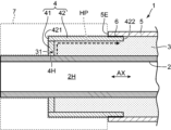
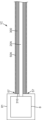
- FIG. 1 is a cross-sectional view showing a first embodiment of a cryogenic fluid pipe according to the present disclosure.
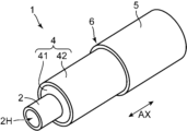
- FIG. 2 is a perspective view of the cryogenic fluid piping of FIG.
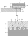
- FIG. 3 is a cross-sectional view of the welded portion between the end seal and the gas barrier, with an enlarged cross-sectional view of the welded portion added.
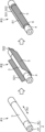
- FIG. 4 is a perspective view showing an example of a gas barrier construction process.
- FIG. 5A is a perspective view showing another example of a gas barrier construction process.
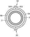
- FIG. 5B is a cross-sectional view taken along line VB-VB in FIG. 5A.
- FIG. 6 is a cross-sectional view showing a second embodiment of a cryogenic fluid pipe according to the present disclosure.
- FIG. 7 is a cross-sectional view showing a third embodiment of a cryogenic fluid pipe according to the present disclosure.
- FIG. 8 is a cross-sectional view showing a fourth embodiment of a cryogenic fluid pipe according to the present disclosure
- the cryogenic fluid piping of the present disclosure is a piping through which a cryogenic fluid is passed for the purpose of transportation or the like.
- the cryogenic fluid includes cryogenic fluids such as liquefied natural gas (LNG) and also cryogenic fluids whose liquefaction temperature is even lower.
- a cryogenic fluid is a fluid in a temperature range that liquefies the surrounding air, or a fluid in a temperature range that liquefies the oxygen or nitrogen contained in the surrounding air.
- the cryogenic fluid is liquefied hydrogen, liquefied helium, or the like.
- the cryogenic fluid may be hydrogen gas, helium gas, or the like in a cryogenic temperature range.
- Fig. 1 is a cross-sectional view showing a cryogenic fluid pipe 1 according to a first embodiment of the present disclosure
- Fig. 2 is a perspective view of the cryogenic fluid pipe 1 of Fig. 1.
- the cryogenic fluid pipe 1 includes a pipe body 2, a thermal insulation layer 3, an end seal 4, and a gas barrier 5.
- the gas barrier 5 includes a welded portion 6.
- the pipe body 2 is covered with the thermal insulation layer 3.
- the thermal insulation layer 3 is covered with the gas barrier 5.
- ⁇ Description of each part of the low-temperature fluid piping> 1 and 2 show a terminal portion of a cryogenic fluid pipe 1 where an intermediate connection or end treatment is performed.
- a predetermined length of the pipe body 2 is exposed in the tube axis direction AX beyond the insulating layer 3.
- a predetermined region in the tube axis direction AX including a layer end portion 31 which is an edge of the insulating layer 3 is exposed and not covered by a gas barrier 5.
- the portion of the insulating layer 3 which is not covered by the gas barrier 5 is covered by an end seal 4.
- the exposed portions of the pipe body 2 and the end seal 4 are covered by an insulating cover 7.
- the insulating cover 7 is a member which insulates the intermediate connection portion or the end portion of the cryogenic fluid pipe 1.
- the insulating cover 7 is detachably attached to the intermediate connection portion or the end portion.
- the piping body 2 is a metallic cylindrical body through which a low-temperature fluid passes.
- the piping body 2 has a cylindrical passage 2H sealed inside.
- a single pipe made of stainless steel or aluminum can be used as the piping body 2.
- a low-temperature fluid passes through the passage 2H of the piping body 2 for the purpose of transferring, storing, and keeping the low-temperature fluid cold.
- a vacuum insulated multi-wall pipe may be used for transferring a low-temperature fluid, particularly for transferring an extremely low-temperature fluid such as liquefied hydrogen. As described later in FIG. 7, the present disclosure does not exclude the use of a vacuum insulated multi-wall pipe as a pipe through which a low-temperature fluid passes.
- the piping body 2 made of a metallic single pipe is used, the work of establishing and releasing a vacuum environment is not required when forming and dismantling an intermediate connection part or an end part of the low-temperature fluid pipe 1, and the amount of construction work can be reduced.
- the weight of the low-temperature fluid pipe 1 can be reduced compared to, for example, a vacuum insulated multi-wall pipe.
- the insulating layer 3 surrounds the pipe body 2 and insulates the pipe body 2.
- the material of the insulating material used for the insulating layer 3 can be a petroleum-based synthetic rubber material such as ethylene propylene rubber, an organic polymer material such as polyurethane foam or polyethylene foam, a fiber material such as glass fiber or glass wool, or an inorganic material such as perlite, foam glass, or aerogel.
- the insulating layer 3 can be formed of multiple types of insulating materials or a single insulating material, and may include a material that does not have an insulating function.
- the insulating layer 3 can be formed around the pipe body 2 in a form in which a sheet-like insulating material is wrapped around the outer periphery of the pipe body 2.
- the end seal 4 covers the exposed portion near the end of the insulation layer 3.
- the end seal 4 can be made of, for example, stainless steel or aluminum. It is preferable to make the pipe body 2 and the end seal 4 from the same metal material. In this case, the thermal expansion coefficients of both are the same, and the internal stress of the pipe body 2 and the end seal 4 that occurs due to temperature changes can be suppressed.
- the end seal 4 includes a plate portion 41 and a tube portion 42.
- the plate portion 41 includes a hole portion 4H through which the piping body 2 penetrates, and has a disk shape extending radially outward from the piping body 2. In other words, the plate portion 41 protrudes radially outward from the outer circumferential surface of the piping body 2 when attached to the piping body 2.
- the layer end portion 31 of the insulation layer 3 has a cross section that faces parallel to the plate portion 41. The plate portion 41 abuts against the layer end portion 31. In this embodiment, the plate portion 41 is attached to the outer circumferential surface of the piping body 2 by welding.
- the plate portion 41 is welded to the piping body 2 at the periphery of the hole portion 4H with the piping body 2 inserted through the hole portion 4H.
- the plate portion 41 may be made integral with the piping body 2 by machining or the like.
- the cylindrical portion 42 extends in the pipe axis direction AX of the pipe body 2 and has a cylindrical shape surrounding the pipe body 2.
- the cylindrical portion 42 covers a portion of a predetermined length in the pipe axis direction AX from the layer end portion 31 of the insulation layer 3.
- the cylindrical portion 42 includes one end 421 located on the plate portion 41 side and the other end 422 located on the edge 5E side of the gas barrier 5.
- the inner surface of the one end 421 is welded to the outer surface of the plate portion 41.
- the welded portion of the inner surface of the one end 421 may be the one end region including the one end 421 and the vicinity of the one end 421.
- the cylindrical portion 42 may be formed as a cylindrical portion 42 integral with the plate portion 41 by machining or the like.
- the other end 422 extends beyond the edge 5E of the gas barrier 5 and enters the inside of the gas barrier 5 in the direction from the plate portion 41 in the pipe axis direction AX toward the gas barrier 5.
- the other end region, including the other end 422 and the vicinity of the other end 422 that overlaps with the gas barrier 5, is welded to the gas barrier 5.
- the gas barrier 5 surrounds the insulating layer 3 and isolates it from the outside air. In other words, the gas barrier 5 covers the outer peripheral surface of the insulating layer 3, thereby preventing outside air from entering the insulating layer 3.
- a non-breathable metal-resin composite sheet, a resin sheet, a metal sheet, or the like can be used as the gas barrier 5. Specific examples of preferred gas barriers 5 will be described later with reference to FIG. 3.
- the gas barrier 5 includes a welded portion 6 that is welded to the end seal 4.
- the insulating layer 3 at the end portion that is not covered by the gas barrier 5 is covered by the end seal 4 as described above.
- the welded portion 6 joins the gas barrier 5 and the tubular portion 42 of the end seal 4 so as to be airtight.
- the welded portion 6 is a joint where the constituent material of the gas barrier 5 and the constituent material of the end seal 4 are in direct contact with each other and joined together without using any intermediate material such as adhesive.
- a gap may occur at the contact area between the gas barrier 5 and the end seal 4 due to the difference in thermal expansion coefficient between the two.
- the insulation layer 3 is sealed by the outer circumferential surface of the pipe body 2, the end seal 4, and the gas barrier 5. Therefore, the intrusion of outside air into the insulation layer 3 can be suppressed for a long period of time.
- the low-temperature fluid passed through the pipe body 2 is liquefied hydrogen, if air intrudes into the insulation layer 3, liquefied air may be generated by the cold heat from the pipe body 2.
- the insulation layer 3 since the insulation layer 3 is sealed, the generation of liquefied air can be suppressed.
- the mechanical strength can be increased compared to when the gas barrier 5 and the end seal 4 are joined with an adhesive.
- the gas barrier 5 includes a resin layer in the surface layer portion that becomes the welded portion 6, and the resin layer is welded to the end seal 4.
- the gas barrier 5 is made of a flexible film formed by laminating an aluminum foil and a resin film.
- the gas barrier 5 includes, for example, an outer resin layer 51, an inner resin layer 52, a first aluminum foil layer 53, a second aluminum foil layer 54, and an adhesive layer 55. Note that the number of resin layers and the number of aluminum foil layers included in the gas barrier 5 are merely examples.
- the outer resin layer 51 is located at the outermost layer of the gas barrier 5 when the gas barrier 5 is attached to the insulation layer 3.
- the outer side when the gas barrier 5 is attached to the insulation layer 3 refers to the side from the insulation layer 3 to the gas barrier layer in the radial direction of the low-temperature fluid pipe 1, and the inner side refers to the opposite side.
- the outer resin layer 51 functions as a protective layer that protects, for example, the insulation layer 3 from external forces.
- a resin film such as nylon or polyethylene terephthalate can be used.
- an engineering plastic may be used as the outer resin layer 51.
- a thermoplastic resin may be used as the outer resin layer 51.
- the inner resin layer 52 is located at the innermost layer of the gas barrier 5 when the gas barrier 5 is attached to the insulating layer 3.
- the inner resin layer 52 is a layer that comes into contact with the tubular portion 42 of the end seal 4, and is a layer that forms the welded portion 6 by thermal welding.
- a thermoplastic resin film such as polyethylene or polypropylene can be used as the inner resin layer 52. If fire resistance is required for the inner resin layer 52, an engineering plastic may be used as the inner resin layer 52.
- the adhesive layer 55 is disposed between the outer resin layer 51 and the first aluminum foil layer 53, between the first aluminum foil layer 53 and the second aluminum foil layer 54, and between the second aluminum foil layer 54 and the inner resin layer 52, respectively, and bonds these adjacent layers together.
- the adhesive layer 55 may be an adhesive or a thermoplastic resin film for heat welding. When the latter is used as the adhesive layer 55, the thermoplastic resin film is heated to a temperature above the melting point of the resin material during the manufacture of the gas barrier 5, and heat-welded to the adjacent layers.
- the heat welding referred to in this embodiment is performed by melting at least one of the two joining parts to be joined by heating, and bringing the joining parts into contact with each other. The joining parts are then cooled while still in contact with each other, thereby joining the joining parts to each other. When bringing the joining parts into contact with each other, the joining parts may be pressed against each other to apply pressure.
- the gas barrier 5 is made of a flexible film laminated with metal foil and resin film, as in this embodiment, the following advantages are obtained.
- the gas barrier 5 can be joined to the end seal 4 at the welded portion 6 by heat welding.
- the gas barrier 5 can be heat-welded to the end seal 4 simply by applying heat equal to or higher than the melting point of the constituent resin of the inner resin layer 52. Therefore, the construction work is relatively easy.
- the joining is by welding, the joint between the gas barrier 5 and the end seal 4 is also airtight.
- the flexible film laminated with metal foil and resin film is a relatively lightweight material, the weight of the low-temperature fluid piping 1 can be reduced compared to, for example, a vacuum insulated multi-wall pipe.
- the use of the flexible film also contributes to durability and excellent maintainability.
- the inside of the gas barrier 5 becomes colder and negative pressure is created due to the condensation of the air.
- the welded portion 6 provides high airtightness, so the inside of the gas barrier 5 is more easily negatively pressurized. This negative pressure causes a stress to act on the gas barrier 5, pulling it radially inward. If the gas barrier 5 is a relatively rigid structure, there is a concern that the gas barrier 5 will be damaged by this stress. However, if the gas barrier 5 is made of the flexible film, it can flexibly follow and deform even when subjected to the stress associated with negative pressure, and has excellent durability.
- the gas barrier 5 when the gas barrier 5 is made of a flexible film, defects such as pinholes and tears that occur in the gas barrier 5 are easy to find. As described above, when a low-temperature fluid is circulated through the piping body 2, the gas barrier 5 is deformed by the negative pressure. However, if the above-mentioned defect occurs, the airtightness is destroyed and the gas barrier 5 does not deform. In other words, if the gas barrier 5 does not deform due to the negative pressure, it can be assumed that some kind of defect has occurred in the gas barrier 5. Therefore, maintainability can be improved.
- ⁇ Formation of rough surface layer on end seal> 3 shows an enlarged view of a more preferred embodiment of the welded portion 6.
- the end seal 4 has a rough surface layer 43 in the area facing the welded portion 6.
- the area of the end seal 4 facing the welded portion 6 may be a smooth surface, but by forming the rough surface layer 43 in the welded portion 6, the bonding strength between the end seal 4 and the gas barrier 5, as well as the airtightness of the welded portion 6, can be further improved.
- the rough surface layer 43 is formed on the outer peripheral surface of the tube portion 42 in the region near the other end 422 of the tube portion 42, and includes a number of minute protrusions 44 and recesses 45.
- the recesses 45 desirably have a wedge-shaped cross-sectional shape that is wide near the bottom surface and narrow near the opening.
- the molten portion 52A of the inner resin layer 52 that melted during the thermal welding process enters the recesses 45. Due to the characteristics described above, the engagement between the molten portion 52A and the recesses 45 creates an anchor effect, and the rough surface layer 43 and the welded portion 6 are firmly joined.
- the rough surface layer 43 can be formed by chemical etching using a chemical solution, shot blasting with fine particles, sanding using a roughening tool, or the like.
- the above-mentioned chemical etching is performed by immersing the area near the other end 422 of the tube portion 42 in a phosphate-based chemical solution for a predetermined period of time.
- the end seal 4 covers the exposed portion from the gas barrier 5 near the layer end 31 of the insulation layer 3. Attachment of the end seal 4 suppresses the generation of liquefied air associated with the intrusion of outside air into the insulation layer 3.
- the shape characteristics of the end seal 4 in this embodiment have the advantage of suppressing heat transfer from the piping body 2 to the gas barrier 5, as well as heat input from the gas barrier 5 to the piping body 2.
- the end seal 4 covers the exposed portion of the insulation layer 3 as described above, and therefore is also a member that connects the pipe body 2 and the gas barrier 5. For this reason, the end seal 4 can be a heat transfer path between the pipe body 2 and the gas barrier 5. In other words, the cold heat of the pipe body 2 during the flow of liquid hydrogen can be transferred to the gas barrier 5 through the end seal 4. In this case, the temperature of the welded portion 6 between the end seal 4 and the gas barrier 5 decreases, which may cause the gas barrier 5 to peel off. Conversely, the gas barrier 5 exposed to the outside air becomes a heat source, and heat may be input from the gas barrier 5 to the pipe body 2 through the end seal 4. In this case, boil-off gas of the liquefied hydrogen may be generated within the pipe body 2.
- the end seal 4 includes a disk-shaped plate portion 41 and a tubular portion 42 extending in the tube axis direction AX of the piping body 2.
- FIG. 1 also shows the heat transfer path HP of the end seal 4. Since the end seal 4 includes not only the plate portion 41 but also the tubular portion 42, the heat transfer path HP also has a portion extending in the tube axis direction AX. In other words, the heat transfer path HP is longer by the length of the tubular portion 42 than when the end seal 4 is composed of only the portion corresponding to the plate portion 41.
- the low-temperature fluid piping 1 of the present disclosure has the layer end portion 31 of the insulating layer 3 protrude in the tube axis direction AX beyond the edge 5E of the gas barrier 5, and the end seal 4 is provided with a tubular portion 42 that covers the protruding portion. Since the low-temperature fluid piping 1 of the present disclosure has a long heat transfer path HP as described above, the cold heat of the piping body 2 is less likely to be transferred to the gas barrier 5. This prevents the gas barrier 5 from peeling off due to cooling of the welded portion 6. It also prevents heat input from the gas barrier 5 to the pipe body 2.
- the end seal 4 is provided with a cylindrical portion 42 to lengthen the heat transfer path HP.
- a cylindrical portion shaped like a bellows or a cylindrical portion with a rectangular cross section and continuous projections and recesses may be used to lengthen the heat transfer path HP of the low-temperature fluid piping 1.
- the insulation layer 3 is covered with the gas barrier 5, the plate portion 41 of the end seal 4 is joined to the piping body 2 by welding, and the other end 422 of the tubular portion 42 is joined to the gas barrier 5 by a welding portion 6. Therefore, the insulation layer 3 is disposed in a space sealed by the outer peripheral surface of the piping body 2, the end seal 4, and the gas barrier 5. In other words, the insulation layer 3 is disposed in a space with a high airtightness. Therefore, the space in which the insulation layer 3 is disposed may be reduced in pressure.
- the insulating effect of the insulating layer 3 can be further improved.
- drawing a vacuum to reduce the pressure in the space in which the insulating layer is placed can cause problems with outgassing from the adhesive.
- the end seal 4 and the gas barrier 5 are joined with the welded portion 6, so the problem of outgassing does not occur.
- ⁇ Gas barrier construction process> 4 is a perspective view showing an example of a process for applying the gas barrier 5.
- the process includes steps P1 to P3, which are executed in sequence.
- step P1 the insulation layer 3 is mounted on the piping body 2, and an end seal 4 is attached to an end portion 31 of the insulation layer 3.
- step P2 a sheet-like gas barrier 5 is prepared.
- the gas barrier 5 has a size that allows the exposed insulation layer 3 to be circumferentially wrapped.
- the gas barrier 5 is wound around the insulation layer 3 so that an end region in the pipe axis direction AX overlaps with a part of the tubular portion 42 of the end seal 4.
- the gas barrier 5 is welded.
- An overlapping portion is formed by overlapping one end 501 and the other end 502 of the gas barrier 5 in the circumferential direction.
- the overlapping portion is heated to heat-weld the inner resin layers 52 shown in FIG. 3, that is, the inner resin layer 52 at the one end 501 and the inner resin layer 52 at the other end 502.
- an axial welded portion 61 extending in the tube axis direction AX is formed in the gas barrier 5.
- one of the inner resin layers 52 at the one end 501 and the other end 502 may be heat-welded to the outer resin layer 51 at the other end 501.
- the gas barrier 5 may be wrapped around the insulating layer 3 so that the one end 501 and the other end 502 overlap in the radial direction, and the overlapping portion of the one end 501 and the other end 502 may be heated and heat-welded.
- the end of the gas barrier 5 in the tube axis direction AX is heat welded to the end seal 4, forming a circumferentially extending welded portion 6.
- the formation of the circumferential welded portion 6 and the axial welded portion 61 increases the airtightness of the gas barrier 5.
- one end 501 and the other end 502 of the gas barrier 5 may be heat-welded in advance to form a cylindrical shape, and then the cylindrical gas barrier 5 may be placed on the insulating layer 3.
- the insulating layer 3 is wrapped with the gas barrier 5
- air may be trapped between the outer peripheral surface of the insulating layer 3 and the inner peripheral surface of the gas barrier 5.
- a process of sucking out the air between the insulating layer 3 and the gas barrier 5 may be performed, and then the gas barrier 5 may be heat-welded to make it airtight.
- the welding of a part of the circumferential welded portion 6 and the axial welded portion 61 may be left incomplete, and after the air is sucked out from the non-welded portion, the non-welded portion may be heat-welded to make the gas barrier 5 airtight. If the length of the insulating layer 3 in the tube axis direction AX is long, multiple sheet-like gas barriers 5 may be arranged in the tube axis direction AX and connected to each other by heat fusion.
- FIG. 5A is a perspective view showing another example of the construction process of the gas barrier 5, and FIG. 5B is a cross-sectional view along line VB-VB in FIG. 5A.
- a sheet-like first gas barrier 5A and second gas barrier 5B are used as the gas barrier 5 that covers the insulating layer 3.
- the first gas barrier 5A covers one half of the circumferential surface of the insulating layer 3, and the second gas barrier 5B covers the other half.
- two circumferential ends 503 of the first gas barrier 5A and two circumferential ends 504 of the second gas barrier 5B are butted against each other and heat-welded to form a pair of axial welds 62.
- the axial welds 62 may be left protruding radially outward, or may be folded along the circumferential surface of the gas barrier 5 and heat-welded or taped.
- the insulating layer 3 may be wrapped with three or more gas barrier sheets, and adjacent gas barrier sheets may be heat-welded to each other. When the pipe diameter of the piping body 2 is large, the outer diameter of the insulating layer 3 also becomes large. In this case, it may be difficult to wrap the insulating layer 3 with one gas barrier sheet. By wrapping the insulating layer 3 with multiple gas barrier sheets, the construction of the gas barrier 5 can be simplified.
- FIG. 6 is a cross-sectional view showing a cryogenic fluid pipe 1A of the second embodiment.
- the cryogenic fluid pipe 1A includes a pipe body 2, a heat insulating layer 3, an end seal 40, and a gas barrier 5.
- the second embodiment differs from the first embodiment in that the end seal 40 does not have a portion corresponding to the cylindrical portion 42 extending in the pipe axis direction AX.
- the end seal 40 includes a hole 40H through which the piping body 2 passes, and has a disk shape extending radially outward from the piping body 2.
- the piping body 2 is inserted into the hole 40H, and the periphery of the hole 40H is welded to the piping body 2.
- the outer surface of the end seal 40 in the pipe axis direction AX is flush with the edge 5E of the gas barrier 5.
- the inner surface of the end seal 40 in the pipe axis direction AX abuts against the layer end 31 of the insulation layer 3.
- the exposed portion of the piping body 2 is covered with an insulation cover 7.
- the outer peripheral edge of the end seal 40 is the part that is welded to the gas barrier 5.
- the gas barrier 5 has a welded portion 60 on the inner surface near the edge 5E that is welded to the end seal 40.
- the form of the welded portion 60 is substantially the same as in the first embodiment.
- the inner resin layer 52 of the gas barrier 5 is thermally welded to the outer peripheral edge of the end seal 40, thereby forming the welded portion 60.
- the welding of the hole portion 40H and the formation of the welded portion 60 improve the airtightness of the arrangement space of the insulation layer 3 by the end seal 40. Therefore, it is possible to suppress the intrusion of outside air into the insulation layer 3.
- the outer peripheral edge of the end seal 40 may be a rough surface layer 43 as shown in FIG. 3.
- FIG. 7 is a cross-sectional view showing a cryogenic fluid pipe 1B according to a third embodiment.
- the cryogenic fluid pipe 1B includes an inner pipe 21 as a pipe body, a heat insulating layer 30, an outer pipe 22 as a vacuum jacket, and a gas barrier 50.
- the inner pipe 21 is a metal pipe through which a cryogenic fluid passes.
- the outer pipe 22 is disposed coaxially with the inner pipe 21 and covers the inner pipe 21 with a space in the radial direction.
- the inner pipe 21 and the outer pipe 22 constitute a vacuum double pipe 20. The space between the inner pipe 21 and the outer pipe 22 is depressurized to form a vacuum insulation space.
- the low-temperature fluid piping 1B includes an exposed portion PA where the outer pipe 22 has been removed and the inner pipe 21 has been exposed.
- the exposed portion PA is, for example, a portion where the inner pipes 21 are connected to each other in an intermediate connection portion that connects a pair of vacuum double pipes 20.
- the outer pipe 22 is removed in order to connect the inner pipes 21 to each other by welding or the like, and a predetermined length of the inner pipe 21 is exposed in the pipe axis direction AX.
- a sealant 221 is attached to the end portion 22E of the outer pipe 22, and the space between the inner pipe 21 and the outer pipe 22 is kept airtight.
- the insulating layer 30 covers the exposed portion PA of the inner pipe 21 and the vicinity of the end 22E of the outer pipe 22.
- the insulating layer 30 mainly insulates the inner pipe 21 at the exposed portion PA.
- the outer pipe 22 covers the outer circumference of the inner pipe 21 other than the exposed portion PA through a reduced pressure space, and insulates the inner pipe 21.
- the insulating layer 30 can be formed, for example, by winding a sheet-like insulating material on the exposed portion PA so as to straddle the ends 22E of a pair of opposing outer pipes 22. In the third embodiment, as shown by the dotted line in FIG.
- the sealing material 221 adjacent to the insulating layer 30 in the tube axis direction AX and the end 22E of the outer pipe 22 adjacent to the insulating layer 30 in the radial direction form an end seal 4A that seals the layer end of the insulating layer 30.
- the gas barrier 50 covers the outer periphery of the insulating layer 30 and isolates the insulating layer 30 from the outside air.
- the gas barrier 50 may be a non-breathable metal-resin composite sheet, a resin sheet, a metal sheet, or the like.
- a laminate film of aluminum foil and a resin film as shown in FIG. 3 may be used as the gas barrier 50.
- the gas barrier 50 includes a welding portion 63 that is welded to the end 22E of the outer tube 22 as the end seal 4A.
- the welding portion 63 is located at the end 56 of the gas barrier 50 in the tube axis direction AX.
- the welding portion 63 can be formed in a manner in which the resin layer included in the gas barrier 50 is heat-welded to the surface of the outer tube 22.
- the area of the end seal 4A facing the welding portion 63 may be processed to have a rough surface layer 43 as shown in FIG. 3.
- the gas barrier 50 By covering the insulating layer 30 with the gas barrier 50 including the welded portion 63, it is possible to prevent outside air from entering the insulating layer 30.
- a gap may occur at the contact point between the gas barrier 50 and the outer tube 22 due to the difference in the thermal expansion coefficient between the two.
- the gas barrier 50 is welded to the outer tube 22 by the welded portion 63. Therefore, even if there is a difference in the thermal expansion coefficient, the airtightness of the contact point between the gas barrier 50 and the outer tube 22 is ensured, and it is possible to prevent outside air from entering the insulating layer 30 for a long period of time.
- the mechanical strength can be increased compared to when the gas barrier 50 and the outer tube 22 are joined with an adhesive.
- FIG. 8 is a cross-sectional view showing a cryogenic fluid pipe 1C according to a fourth embodiment.
- the cryogenic fluid pipe 1C is a pipe connected to a piping device 8, and includes a pipe main body 20A, a heat insulating layer 300, and a gas barrier 50A.
- the pipe main body 20A is a metal pipe through which a cryogenic fluid passes.
- the heat insulating layer 300 covers the outer periphery of the pipe main body 20A and insulates the pipe main body 20A.
- the gas barrier 50A covers the outer periphery of the heat insulating layer 300 and isolates the heat insulating layer 300 from the outside air.
- the piping equipment 8 is, for example, a pump or compressor that sends liquid hydrogen to the piping body 2, or a heat exchanger that uses liquid hydrogen as a heat medium.
- the piping equipment 8 is covered with a vacuum jacket 81 to keep it cool or to prevent the generation of liquefied air.
- the edge 57 of the gas barrier 50A is welded to the vacuum jacket 81.
- a laminate film of aluminum foil and resin film can be used as the gas barrier 50A, and the edge 57 can be heat welded to the vacuum jacket 81.
- the portion of the vacuum jacket 81 that abuts against the layer end 310 of the insulating layer 300 serves as an end seal.
- the insulating layer 300 is made airtight by welding the edge 57 of the gas barrier 50A to the vacuum jacket 81.
- the low-temperature fluid pipe comprises a metal pipe body through which a low-temperature fluid passes, an end seal protruding radially outward from the outer circumferential surface of the pipe body, an insulating layer surrounding the pipe body and including a layer end portion facing the end seal, and a gas barrier surrounding the insulating layer and including a welded portion welded to the end seal.
- the insulation layer is surrounded by a gas barrier and the end of the layer is covered by an end seal, so that the intrusion of outside air into the insulation layer can be suppressed.
- a gap can occur at the contact point between the end seal and the gas barrier due to the difference in the thermal expansion coefficient between the two.
- the gas barrier includes a welded portion that is welded to the end seal. Therefore, even if there is a difference in the thermal expansion coefficient, the airtightness of the contact point between the end seal and the gas barrier is ensured, and the intrusion of outside air can be suppressed for a long period of time.
- the mechanical strength can be increased compared to when the end seal and the gas barrier are joined with an adhesive.
- the low-temperature fluid piping of the second aspect is the low-temperature fluid piping of the first aspect, in which the gas barrier includes a resin layer at least on the surface portion of the welded portion, and the resin layer is welded to the end seal.
- the resin layer of the gas barrier can be melted to weld the gas barrier to the end seal. This improves the workability of the welded portion compared to welding, etc.
- the third aspect of the low-temperature fluid piping is the low-temperature fluid piping of the first or second aspect, in which the end seal has a roughened surface layer in the area facing the welded portion.
- the anchor effect based on the presence of the rough surface layer can further improve the bond strength and airtightness between the end seal and the gas barrier at the welded portion.
- the low-temperature fluid piping of the fourth aspect is the low-temperature fluid piping of the first to third aspects, in which the insulating layer is sealed by the outer circumferential surface of the piping body, the end seal, and the gas barrier, and is disposed in a reduced-pressure space.
- the area where the insulating layer is placed is a reduced pressure environment, which can improve the insulating effect on the piping. Furthermore, if the end seal and the gas barrier are joined with an adhesive, outgassing from the adhesive can become a problem when a vacuum is drawn to reduce the pressure in the area where the insulating layer is placed. However, in this aspect, the end seal and the gas barrier are joined by welding, so the problem of outgassing does not occur.
- the cryogenic fluid piping of the fifth aspect is the cryogenic fluid piping of the first to fourth aspects, in which the end seal has a hole that penetrates the piping body, is a plate-shaped end seal plate portion that extends radially outward from the piping body and is in contact with the layer end portion of the insulating layer, and is a cylindrical end seal tubular portion that surrounds the piping body, is connected to the end seal plate portion at one end region, and has the other end region welded to the welded portion of the gas barrier.
- not only the end seal plate portion but also the end seal tube portion is interposed between the pipe body and the gas barrier. This lengthens the heat transfer path between the pipe body and the gas barrier, making it difficult for the cold heat of the pipe body to be transferred to the gas barrier. This makes it possible to suppress peeling of the gas barrier due to cooling of the welded portion. It also makes it possible to suppress heat input to the pipe body from the gas barrier exposed to the outside air.
- the sixth aspect of the low-temperature fluid piping is the low-temperature fluid piping of the first to fifth aspects, in which the low-temperature fluid passed through the piping body is liquefied hydrogen.
- Liquefied hydrogen has cold energy that generates liquefied air. If the sealing ability of the end seal is reduced and outside air penetrates the insulation layer and comes into contact with the piping body, liquefied air will be generated. According to the sixth aspect, the sealing ability of the end seal is ensured by the welded portion, so the generation of liquefied air can be suppressed.
- the low-temperature fluid pipe comprises a metal pipe body through which the low-temperature fluid passes, a heat insulating layer covering the outer periphery of a first portion of the pipe body, a vacuum jacket covering the outer periphery of a second portion of the pipe body that is different from the first portion through a reduced pressure space, and a gas barrier covering the outer periphery of the heat insulating layer and including a welded portion welded to the vacuum jacket.
- the insulating layer is covered with a gas barrier that includes a portion welded to the vacuum jacket, so that the intrusion of outside air into the insulating layer can be suppressed. Gaps can occur at the contact points between the gas barrier and the vacuum jacket due to the difference in the thermal expansion coefficients of the two.
- the gas barrier includes a welded portion that is welded to the vacuum jacket. Therefore, even if there is a difference in the thermal expansion coefficients, the airtightness of the contact points between the gas barrier and the vacuum jacket is ensured, and the intrusion of outside air can be suppressed for a long period of time.
- the mechanical strength can be increased compared to when the gas barrier and the vacuum jacket are joined with an adhesive.
- the low-temperature fluid piping according to the eighth aspect is the low-temperature fluid piping according to the seventh aspect, in which the gas barrier includes a resin layer at least on the surface portion of the welded portion, and the resin layer is welded to the vacuum jacket.
- the resin layer of the gas barrier can be melted to weld the gas barrier to the vacuum jacket. This improves the workability of the welded portion compared to welding, etc.
- the ninth aspect of the low-temperature fluid piping is the low-temperature fluid piping of the seventh or eighth aspect, in which the end seal has a roughened surface layer in the area facing the welded portion.
- the anchor effect based on the presence of the rough surface layer can further improve the bonding strength and airtightness between the gas barrier and the vacuum jacket at the welded portion.
Landscapes
- Engineering & Computer Science (AREA)
- General Engineering & Computer Science (AREA)
- Mechanical Engineering (AREA)
- Thermal Insulation (AREA)
Abstract
Description
図1は、本開示の第1実施形態に係る低温流体用配管1を示す断面図、図2は、図1の低温流体用配管1の斜視図である。低温流体用配管1は、配管本体2、断熱層3、エンドシール4およびガスバリア5を含む。ガスバリア5は、溶着部6を含む。配管本体2は断熱層3で覆われている。断熱層3は、ガスバリア5で覆われている。
図1および図2は、低温流体用配管1の中間接続あるいは終端処理が行われる端末部分を示している。当該端末部分では、配管本体2が断熱層3よりも管軸方向AXに所定長だけ露出している。また、当該端末部分では、断熱層3の端縁である層端部31を含む管軸方向AXの所定領域が、ガスバリア5で覆われずに露出している。断熱層3のガスバリア5で覆われていない部分は、エンドシール4で覆われている。配管本体2およびエンドシール4の露出部分は、断熱カバー7で覆われる。断熱カバー7は、低温流体用配管1の中間接続部や終端部などを断熱する部材である。断熱カバー7は、前記中間接続部または前記終端部に対して着脱可能に装着される。
図3は、エンドシール4とガスバリア5との溶着部6の断面図であって、溶着部6の拡大断面図を付記した図である。ガスバリア5は、溶着部6となる表層部分に樹脂層を含み、当該樹脂層がエンドシール4に溶着される。ガスバリア5は、アルミ箔と樹脂フィルムとをラミネートした、可撓性を有するフィルムからなる。具体的にはガスバリア5は、例えば外側樹脂層51、内側樹脂層52、第1アルミ箔層53、第2アルミ箔層54および接着層55を含む。なお、ガスバリア5に含まれる樹脂層の数およびアルミ箔層の数は一例である。
図3には、溶着部6のより好ましい態様が、拡大図にて示されている。エンドシール4は、溶着部6に対向する領域に、表面が粗化された粗面表層43を有する。前記エンドシール4の溶着部6に対向する領域は平滑面であっても良いが、当該溶着部6に粗面表層43を形成することで、エンドシール4とガスバリア5との接合強度、ならびに溶着部6の気密性を一層向上させることができる。
エンドシール4は、断熱層3の層端部31付近における、ガスバリア5からの露出部分を覆っている。エンドシール4の取り付けにより、断熱層3への外気に侵入に伴う液化空気の発生が抑制される。この効果に加え、本実施形態のエンドシール4の形状的な特徴により、配管本体2からガスバリア5への伝熱、並びにガスバリア5から配管本体2への入熱を抑制出来る利点もある。
本実施形態では、断熱層3がガスバリア5で覆われ、エンドシール4の板部41は配管本体2に溶接で接合され、筒部42の他端422が溶着部6によりガスバリア5に接合されている。このため、断熱層3は、配管本体2の外周面、エンドシール4およびガスバリア5によって密閉された空間に配置されている。つまり、気密度の高い空間に断熱層3が配置されている。従って、断熱層3の配置空間を減圧しても良い。
図4は、ガスバリア5の施工プロセスの一例を示す斜視図である。前記施行プロセスは、順次実行される工程P1~P3を含む。工程P1では、配管本体2の上に断熱層3が装着され、断熱層3の層端部31にエンドシール4が取り付けられる。工程P2では、シート状のガスバリア5が準備される。当該ガスバリア5は、露出している断熱層3を周方向に包被できるサイズを有する。ガスバリア5は、管軸方向AXの端部領域がエンドシール4の筒部42の一部と重なり合うように、断熱層3の上に巻かれる。
図6は、第2実施形態の低温流体用配管1Aを示す断面図である。低温流体用配管1Aは、配管本体2、断熱層3、エンドシール40およびガスバリア5を含む。第1実施形態と相違する点は、エンドシール40が、管軸方向AXに延びる筒部42に相当する部分を有していない点である。
図7は、第3実施形態に係る低温流体用配管1Bを示す断面図である。低温流体用配管1Bは、配管本体としての内管21、断熱層30、真空ジャケットとしての外管22、およびガスバリア50を含む。内管21は、低温流体を通す金属製の配管である。外管22は、内管21と同軸に配置され、径方向に空間を介して内管21を覆っている。内管21および外管22は、真空二重管20を構成する。内管21と外管22との間の前記空間は減圧され、真空断熱空間とされる。
図8は、第4実施形態に係る低温流体用配管1Cを示す断面図である。低温流体用配管1Cは、配管用機器8に接続される配管であって、配管本体20A、断熱層300およびガスバリア50Aを含む。配管本体20Aは、低温流体を通す金属製の配管である。断熱層300は、配管本体20Aの外周を覆い、配管本体20Aを断熱している。ガスバリア50Aは、断熱層300の外周を覆い、断熱層300を外気と隔離する。
以上説明した具体的実施形態には、以下の構成を有する開示が含まれている。
Claims (6)
- 低温流体を通す金属製の配管本体と、
前記配管本体の外周面から当該配管本体の径方向外側に突出するエンドシールと、
前記配管本体を取り囲み、前記エンドシールと対向する層端部を含む断熱層と、
前記断熱層を取り囲み、前記エンドシールに溶着される溶着部を含むガスバリアと、を備える低温流体用配管。 - 請求項1に記載の低温流体用配管において、
前記ガスバリアは、少なくとも前記溶着部の表層部分に樹脂層を含み、
前記樹脂層が前記エンドシールに溶着されている、低温流体用配管。 - 請求項1に記載の低温流体用配管において、
前記エンドシールは、前記溶着部に対向する領域に、表面が粗化された粗面表層を有する、低温流体用配管。 - 請求項1に記載の低温流体用配管において、
前記断熱層は、前記配管本体の外周面、前記エンドシールおよび前記ガスバリアによって密閉され、且つ減圧された空間に配置されている、低温流体用配管。 - 請求項1~4のいずれか1項に記載の低温流体用配管において、
前記エンドシールは、
前記配管本体を貫通させる孔部を有し、前記配管本体の径方向外側に延びる板形状のエンドシール板部であって、前記断熱層の層端部と接するエンドシール板部と、
前記配管本体を取り囲む筒形状のエンドシール筒部であって、一端領域において前記エンドシール板部と接続され、他端領域が前記ガスバリアの前記溶着部に溶着されるエンドシール筒部と、を含む、低温流体用配管。 - 請求項1に記載の低温流体用配管において、
前記配管本体に通される低温流体が液化水素である、低温流体用配管。
Priority Applications (1)
| Application Number | Priority Date | Filing Date | Title |
|---|---|---|---|
| JP2025557868A JPWO2025105378A1 (ja) | 2023-11-14 | 2024-11-12 |
Applications Claiming Priority (2)
| Application Number | Priority Date | Filing Date | Title |
|---|---|---|---|
| US202363548435P | 2023-11-14 | 2023-11-14 | |
| US63/548,435 | 2023-11-14 |
Publications (1)
| Publication Number | Publication Date |
|---|---|
| WO2025105378A1 true WO2025105378A1 (ja) | 2025-05-22 |
Family
ID=95742265
Family Applications (1)
| Application Number | Title | Priority Date | Filing Date |
|---|---|---|---|
| PCT/JP2024/040211 Pending WO2025105378A1 (ja) | 2023-11-14 | 2024-11-12 | 低温流体用配管 |
Country Status (2)
| Country | Link |
|---|---|
| JP (1) | JPWO2025105378A1 (ja) |
| WO (1) | WO2025105378A1 (ja) |
Citations (6)
| Publication number | Priority date | Publication date | Assignee | Title |
|---|---|---|---|---|
| JPS49140753U (ja) * | 1973-03-24 | 1974-12-04 | ||
| JPS5463259U (ja) | 1977-10-13 | 1979-05-04 | ||
| JPS5939518A (ja) * | 1982-08-30 | 1984-03-03 | Toyo Soda Mfg Co Ltd | 配管保温保冷材外装の施工方法 |
| JPH08118472A (ja) * | 1994-10-24 | 1996-05-14 | Sekisui Chem Co Ltd | 塩化ビニル系樹脂成形品同士の融着接合方法ならびに塩化ビニル系樹脂分岐管継手の製造方法 |
| JPH1194188A (ja) * | 1997-09-19 | 1999-04-09 | Benkan Corp | 真空断熱体、真空断熱管及び真空断熱熱輸送配管 |
| JP2006242228A (ja) * | 2005-03-01 | 2006-09-14 | Osaka Gas Co Ltd | ホース |
-
2024
- 2024-11-12 JP JP2025557868A patent/JPWO2025105378A1/ja active Pending
- 2024-11-12 WO PCT/JP2024/040211 patent/WO2025105378A1/ja active Pending
Patent Citations (6)
| Publication number | Priority date | Publication date | Assignee | Title |
|---|---|---|---|---|
| JPS49140753U (ja) * | 1973-03-24 | 1974-12-04 | ||
| JPS5463259U (ja) | 1977-10-13 | 1979-05-04 | ||
| JPS5939518A (ja) * | 1982-08-30 | 1984-03-03 | Toyo Soda Mfg Co Ltd | 配管保温保冷材外装の施工方法 |
| JPH08118472A (ja) * | 1994-10-24 | 1996-05-14 | Sekisui Chem Co Ltd | 塩化ビニル系樹脂成形品同士の融着接合方法ならびに塩化ビニル系樹脂分岐管継手の製造方法 |
| JPH1194188A (ja) * | 1997-09-19 | 1999-04-09 | Benkan Corp | 真空断熱体、真空断熱管及び真空断熱熱輸送配管 |
| JP2006242228A (ja) * | 2005-03-01 | 2006-09-14 | Osaka Gas Co Ltd | ホース |
Also Published As
| Publication number | Publication date |
|---|---|
| JPWO2025105378A1 (ja) | 2025-05-22 |
Similar Documents
| Publication | Publication Date | Title |
|---|---|---|
| CN113280253B (zh) | 高压罐的制造方法 | |
| CA2706904C (en) | Liquefied natural gas pipeline with near zero coefficient of thermal expansion | |
| JP4599118B2 (ja) | 燃料タンク | |
| WO2010029730A1 (ja) | 真空断熱材およびその製造方法 | |
| CN103384627A (zh) | 气罐顶盖凸缘部的结构 | |
| CN1391641A (zh) | 管道的管状隔热复合体 | |
| JP5101094B2 (ja) | 冷凍媒体の輸送に使用するラインパイプ | |
| JP4180550B2 (ja) | 極低温複合材圧力容器の製造方法 | |
| JP2007010004A (ja) | ガス容器およびその製造方法 | |
| CN221724075U (zh) | 一种液氢储氢瓶壳体的绝热结构 | |
| KR20080101607A (ko) | 액화가스의 저장실의 벽 구조 및 이를 제조하는 방법 | |
| JP2022180162A (ja) | 極低温流体タンクとその製造方法 | |
| CN219082482U (zh) | 一种耐高压、耐低温管道 | |
| JP2002104297A (ja) | 燃料タンク | |
| JP2010050314A (ja) | Frp製クライオスタット | |
| JP5683894B2 (ja) | ガス輸送用可撓管の端末構造 | |
| WO2023108804A1 (zh) | 增强增韧塑料压力复合管及制造该压力复合管的方法 | |
| JP5030575B2 (ja) | Frp製クライオスタットの製造方法及びfrp製クライオスタット | |
| JP7834334B2 (ja) | 液化ガス容器の製造方法、及び液化ガス容器 | |
| KR20250165918A (ko) | 배관 및 그 배관의 제조 방법 | |
| CN117570356B (zh) | 一种液氢储氢瓶壳体轻量化结构及制造方法 | |
| JP3994432B2 (ja) | 低透過ホースとその製造方法 | |
| KR20260024510A (ko) | 극저온 진공이중단열 저장용기의 제조방법 | |
| JP4587434B2 (ja) | 細径金属管と樹脂製可撓ホースとの接続構造 | |
| GB2624936A (en) | Pipe for transporting cryogenic fluids |
Legal Events
| Date | Code | Title | Description |
|---|---|---|---|
| 121 | Ep: the epo has been informed by wipo that ep was designated in this application |
Ref document number: 24891414 Country of ref document: EP Kind code of ref document: A1 |
|
| ENP | Entry into the national phase |
Ref document number: 2025557868 Country of ref document: JP Kind code of ref document: A |
|
| WWE | Wipo information: entry into national phase |
Ref document number: 2025557868 Country of ref document: JP |
|
| WWE | Wipo information: entry into national phase |
Ref document number: 2024891414 Country of ref document: EP |
|
| ENP | Entry into the national phase |
Ref document number: 2024891414 Country of ref document: EP Effective date: 20260609 |
|
| NENP | Non-entry into the national phase |
Ref country code: DE |