WO2025094635A1 - イオン伝導性構造体の製造方法 - Google Patents
イオン伝導性構造体の製造方法 Download PDFInfo
- Publication number
- WO2025094635A1 WO2025094635A1 PCT/JP2024/036393 JP2024036393W WO2025094635A1 WO 2025094635 A1 WO2025094635 A1 WO 2025094635A1 JP 2024036393 W JP2024036393 W JP 2024036393W WO 2025094635 A1 WO2025094635 A1 WO 2025094635A1
- Authority
- WO
- WIPO (PCT)
- Prior art keywords
- phase
- negative electrode
- ion
- amorphous
- layer
- Prior art date
- Legal status (The legal status is an assumption and is not a legal conclusion. Google has not performed a legal analysis and makes no representation as to the accuracy of the status listed.)
- Pending
Links
Images






Classifications
-
- C—CHEMISTRY; METALLURGY
- C01—INORGANIC CHEMISTRY
- C01G—COMPOUNDS CONTAINING METALS NOT COVERED BY SUBCLASSES C01D OR C01F
- C01G25/00—Compounds of zirconium
-
- C—CHEMISTRY; METALLURGY
- C01—INORGANIC CHEMISTRY
- C01G—COMPOUNDS CONTAINING METALS NOT COVERED BY SUBCLASSES C01D OR C01F
- C01G33/00—Compounds of niobium
-
- C—CHEMISTRY; METALLURGY
- C01—INORGANIC CHEMISTRY
- C01G—COMPOUNDS CONTAINING METALS NOT COVERED BY SUBCLASSES C01D OR C01F
- C01G35/00—Compounds of tantalum
-
- C—CHEMISTRY; METALLURGY
- C01—INORGANIC CHEMISTRY
- C01G—COMPOUNDS CONTAINING METALS NOT COVERED BY SUBCLASSES C01D OR C01F
- C01G53/00—Compounds of nickel
-
- H—ELECTRICITY
- H01—ELECTRIC ELEMENTS
- H01B—CABLES; CONDUCTORS; INSULATORS; SELECTION OF MATERIALS FOR THEIR CONDUCTIVE, INSULATING OR DIELECTRIC PROPERTIES
- H01B13/00—Apparatus or processes specially adapted for manufacturing conductors or cables
-
- H—ELECTRICITY
- H01—ELECTRIC ELEMENTS
- H01M—PROCESSES OR MEANS, e.g. BATTERIES, FOR THE DIRECT CONVERSION OF CHEMICAL ENERGY INTO ELECTRICAL ENERGY
- H01M10/00—Secondary cells; Manufacture thereof
- H01M10/05—Accumulators with non-aqueous electrolyte
- H01M10/052—Li-accumulators
-
- H—ELECTRICITY
- H01—ELECTRIC ELEMENTS
- H01M—PROCESSES OR MEANS, e.g. BATTERIES, FOR THE DIRECT CONVERSION OF CHEMICAL ENERGY INTO ELECTRICAL ENERGY
- H01M10/00—Secondary cells; Manufacture thereof
- H01M10/05—Accumulators with non-aqueous electrolyte
- H01M10/056—Accumulators with non-aqueous electrolyte characterised by the materials used as electrolytes, e.g. mixed inorganic/organic electrolytes
- H01M10/0561—Accumulators with non-aqueous electrolyte characterised by the materials used as electrolytes, e.g. mixed inorganic/organic electrolytes the electrolyte being constituted of inorganic materials only
- H01M10/0562—Solid materials
-
- H—ELECTRICITY
- H01—ELECTRIC ELEMENTS
- H01M—PROCESSES OR MEANS, e.g. BATTERIES, FOR THE DIRECT CONVERSION OF CHEMICAL ENERGY INTO ELECTRICAL ENERGY
- H01M4/00—Electrodes
- H01M4/02—Electrodes composed of, or comprising, active material
- H01M4/13—Electrodes for accumulators with non-aqueous electrolyte, e.g. for lithium-accumulators; Processes of manufacture thereof
- H01M4/139—Processes of manufacture
-
- H—ELECTRICITY
- H01—ELECTRIC ELEMENTS
- H01M—PROCESSES OR MEANS, e.g. BATTERIES, FOR THE DIRECT CONVERSION OF CHEMICAL ENERGY INTO ELECTRICAL ENERGY
- H01M4/00—Electrodes
- H01M4/02—Electrodes composed of, or comprising, active material
- H01M4/62—Selection of inactive substances as ingredients for active masses, e.g. binders, fillers
-
- Y—GENERAL TAGGING OF NEW TECHNOLOGICAL DEVELOPMENTS; GENERAL TAGGING OF CROSS-SECTIONAL TECHNOLOGIES SPANNING OVER SEVERAL SECTIONS OF THE IPC; TECHNICAL SUBJECTS COVERED BY FORMER USPC CROSS-REFERENCE ART COLLECTIONS [XRACs] AND DIGESTS
- Y02—TECHNOLOGIES OR APPLICATIONS FOR MITIGATION OR ADAPTATION AGAINST CLIMATE CHANGE
- Y02E—REDUCTION OF GREENHOUSE GAS [GHG] EMISSIONS, RELATED TO ENERGY GENERATION, TRANSMISSION OR DISTRIBUTION
- Y02E60/00—Enabling technologies; Technologies with a potential or indirect contribution to GHG emissions mitigation
- Y02E60/10—Energy storage using batteries
Definitions
- This disclosure relates to a method for producing an ion-conductive structure.
- Patent Document 1 discloses the formation of an electrode layer having a regular porous structure on a substrate made of a solid electrolyte layer.
- the raw material particles When forming a structure using a slurry in which raw material particles are dispersed in a solvent, the raw material particles are coated with an organic substance to prevent the raw material particles from reacting with the solvent.
- the organically coated raw material particles have an increased specific surface area and a decreased solid content ratio in the slurry. As a result, when a structure is formed from the slurry and then sintered, it does not shrink completely, resulting in a decreased density of the sintered structure.
- the present disclosure aims to improve the density of an ion-conductive structure after sintering in a method for producing an ion-conductive structure using a slurry containing raw material particles.
- one embodiment of the present disclosure includes a slurry preparation process, a structure forming process, and a firing process.
- a slurry is prepared by dispersing composite particles including a core phase made of an oxide-based ion conductor and a shell phase made of an amorphous-containing ion conductor that at least partially contains an amorphous phase in a solvent.
- the slurry is used to form a structure.
- the structure is fired to produce an ion-conductive structure.
- the oxide-based ion conductor has a higher ionic conductivity than the amorphous-containing ion conductor.
- the amorphous-containing ion conductor has a smaller Young's modulus than the oxide-based ion conductor.
- the amorphous-containing ionic conductor of the shell phase has a low melting point, a low Young's modulus, and is an amorphous material, which can improve the coverage of the core phase by the shell phase. This can prevent the oxide-based ionic conductor of the composite particle from reacting with the solvent in the slurry.
- the amorphous-containing ionic conductor contained in the shell phase can promote interparticle bonding during sintering, increasing the density of the sintered structure and forming a dense structure.
- FIG. 1 is a cross-sectional view showing a configuration of a secondary battery according to a first embodiment.
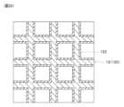
- FIG. 2 is a perspective view showing a specific example of a negative electrode structure.
- FIG. 2 is a perspective view showing a specific example of a negative electrode structure.
- FIG. 2 is a perspective view showing a specific example of a negative electrode structure.
- FIG. 2 is a diagram showing negative electrode side particles.
- 1A and 1B are diagrams showing specific examples of a positive electrode active material and a coating layer.
- 1A and 1B are diagrams showing specific examples of a positive electrode active material and a coating layer.
- 1A and 1B are diagrams showing specific examples of a positive electrode active material and a coating layer.
- FIG. 2 is a diagram showing a specific example of a solid electrolyte composite.
- FIG. 1 is a diagram showing the crystal structure of a pyrochlore-type oxide.
- FIG. 1 is a diagram showing a process for producing a pyrochlore type oxide.
- 1 is a SEM image of pyrochlore oxide and amorphous-containing LiF.
- 1 is a SEM image of a positive electrode active material and a coating layer.
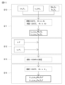
- 11 is a flowchart showing a method for manufacturing a negative electrode structure using a stereolithography 3D printer.
- 11 is a flowchart showing a method for manufacturing a negative electrode structure using an extrusion-type 3D printer.
- 1 is a SEM image of the negative electrode structure.
- 1 is a table showing examples and comparative examples of a negative electrode structure.
- FIG. 1 is a table showing examples and comparative examples of positive electrode active materials.
- FIG. 6 is a diagram showing a negative electrode structure according to a second embodiment.
- FIG. 13 is a diagram showing a negative electrode structure according to a third embodiment.
- FIG. 13 is a diagram showing a negative electrode structure according to a fourth embodiment.
- FIG. 13 is a cross-sectional view showing the configuration of a secondary battery according to a fifth embodiment.
- FIG. 13 is a diagram showing a specific example of a solid electrolyte composite provided in a positive electrode of a fifth embodiment.
- the secondary battery 10 of this embodiment is a lithium ion battery in which lithium ions are conducted as conductive ions.
- the secondary battery 10 of this embodiment is an all-solid-state battery that uses a solid electrolyte in the solid electrolyte layer 15, and is an anode-free battery in which no negative electrode active material is provided in the negative electrode layer 12 in the initial state.
- the secondary battery 10 of this embodiment is a battery cell, and is used as a stack by connecting multiple secondary batteries 10 as necessary.
- the secondary battery 10 has as its components a negative electrode collector 11, a negative electrode layer 12, a positive electrode collector 13, a positive electrode layer 14, and a solid electrolyte layer 15. These components 11 to 15 are stacked in the cell thickness direction.
- the left-right direction in the figure is the cell thickness direction.
- the solid electrolyte layer 15 is sandwiched between a pair of electrode layers 12, 14.
- the solid electrolyte layer 15 and the pair of electrode layers 12, 14 form an electrode structure 16.
- One of the pair of electrode layers 12, 14 is an anode layer 12, and the other is a cathode layer 14.
- the anode layer 12 is provided on one surface of the solid electrolyte layer 15, and the cathode layer 14 is provided on the other surface of the solid electrolyte layer 15.
- the negative electrode layer 12 and the solid electrolyte layer 15 are in contact, and the positive electrode layer 14 and the solid electrolyte layer 15 are in contact.
- the negative electrode layer 12 and the positive electrode layer 14 are connected via the solid electrolyte layer 15.
- the secondary battery 10 is charged and discharged by the conduction of lithium ions between the negative electrode layer 12 and the positive electrode layer 14 via the solid electrolyte layer 15.
- a laminate including the negative electrode layer 12, the positive electrode layer 14, and the solid electrolyte layer 15 is provided between the negative electrode current collector 11 and the positive electrode current collector 13.
- the negative electrode current collector 11 and the negative electrode layer 12 are in contact.
- the positive electrode current collector 13 and the positive electrode layer 14 are in contact.
- the negative electrode current collector 11 and the positive electrode current collector 13 are connected via the laminate.
- the negative electrode collector 11 and the positive electrode collector 13 can be made of any material that can be used as a collector for a lithium-ion battery.
- Cu is used as the negative electrode collector 11
- Al is used as the positive electrode collector 13.
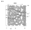
- the negative electrode layer 12 is a structure that constitutes the negative electrode, and receives lithium ions when the secondary battery 10 is charged and releases lithium ions when the secondary battery 10 is discharged.
- the negative electrode layer 12 is an ion-conductive structure that has ion conductivity.
- the negative electrode layer 12 is configured as a porous body having a large number of pores, and the negative electrode layer 12 can be called a porous layer.
- the secondary battery 10 of this embodiment is an anode-free battery, and in the initial state, no negative electrode active material exists in the negative electrode layer 12.
- the initial state is a state in which each component of the secondary battery 10 is assembled, and the secondary battery 10 is not charged.
- elements constituting conductive ions are precipitated in the negative electrode layer 12.
- lithium ions released from the positive electrode active material are conducted from the positive electrode layer 14 to the negative electrode layer 12, and lithium metal is precipitated in the pores of the negative electrode layer 12.
- the lithium metal precipitated in the pores of the negative electrode layer 12 functions as a negative electrode active material.
- a precipitation/dissolution reaction of lithium metal as a negative electrode active material occurs in the pores of the negative electrode layer 12, and lithium ions are received or released.
- the negative electrode layer 12 has a three-dimensional structure.
- the negative electrode layer 12 can be a regular porous structure in which pores are regularly formed, or an irregular porous structure in which pores are irregularly formed.
- Regular porous structures include structures in which many pores of the same shape are formed and the pore diameter is uniform, and structures in which pores of different shapes and pore diameters are regularly arranged and the pore distribution is regular.
- Irregular porous structures include structures in which many pores of different shapes are formed and the pore diameter is nonuniform, and structures in which the pore distribution is irregular, such as when the pore diameter is uniform but the pores are randomly arranged.
- the lithium metal precipitation/dissolution reaction occurs uniformly. Therefore, the ordered porous structure of the negative electrode layer 12 can minimize the localized precipitation of lithium metal, reducing the possibility of a short circuit.
- Forms A1 to A4 in Figures 2 and 3 show specific examples of anode layer 12 with an ordered porous structure.
- Form A5 in Figure 4 shows a specific example of anode layer 12 with an irregular porous structure.
- the up-down direction in the figures is the cell thickness direction.
- anode current collector 11 is provided above anode layer 12.
- the regular pore structures of forms A1 to A4 and the irregular pore structure of form A5 can be manufactured, for example, using a 3D printer.
- the regular pore structures of forms A1 to A4 are obtained by regularly molding a structure having a predetermined shape, resulting in a structure with regularly formed pores.
- the irregular pore structure of form A5 is obtained by, for example, molding using a raw material mixed with a pore-forming agent, and then removing the pore-forming agent by sintering, resulting in a structure with irregularly formed pores.
- the regular porous structure of the negative electrode layer 12 can adopt various forms and is not limited to forms A1 to A4.
- the negative electrode layer 12 of form A1 multiple columnar structures are arranged in parallel.
- the negative electrode layer 12 of form A1 is formed parallel to the cell thickness direction.
- the negative electrode layer 12 of form A1 is formed linearly to connect the solid electrolyte layer 15 and the negative electrode current collector 11, and multiple columnar structures form an ion conduction path. Lithium ions are conducted inside the secondary battery 10 in the cell thickness direction. Therefore, the negative electrode layer 12 of form A1 can improve ion conductivity.
- the bending degree of the multiple columnar structures can be reduced, and ion conduction loss caused by the bending of the columnar structures and the ion conduction path becoming complicated can be reduced. As a result, ion conductivity can be improved, and the input/output performance of the secondary battery 10 can be improved.
- the negative electrode layer 12 of form A2 has a three-dimensional lattice structure, with multiple columnar structures intersecting to form a three-dimensional lattice structure.
- the negative electrode layer 12 of form A2 has structures formed in a direction perpendicular to the cell thickness direction in addition to a direction parallel to the cell thickness direction, and can have improved strength compared to the negative electrode layer 12 of form A1.
- the negative electrode layer 12 of form A3 has a parallel cross structure, and multiple layers each consisting of multiple columnar structures arranged in parallel are stacked in the cell thickness direction. In adjacent layers of columnar structures, the multiple columnar structures are arranged perpendicular to each other.
- the negative electrode layer 12 of form A3 has structures formed in a direction perpendicular to the cell thickness direction in addition to a direction parallel to the cell thickness direction, and can have improved strength compared to the negative electrode layer 12 of form A1. Furthermore, the negative electrode layer 12 of form A3 can be formed by sequentially stacking layers each consisting of multiple columnar structures arranged in parallel, and can have improved formability compared to the negative electrode layer 12 of form A2.
- the negative electrode layer 12 of form A4 has a planar lattice structure, with multiple columnar structures intersecting to form a two-dimensional lattice structure.
- the negative electrode layer 12 of form A4 also has improved strength compared to the negative electrode layer 12 of form A1.
- the negative electrode layer 12 It is desirable for the negative electrode layer 12 to have a pore diameter in the range of 0.1 to 50 ⁇ m. It is also desirable for the negative electrode layer 12 to have a molding width of the structure that forms the pores in the range of 1 to 100 ⁇ m. The molding width of the negative electrode layer 12 is the distance between adjacent pores.
- the negative electrode layer 12 mainly comprises a sintered body obtained by sintering negative electrode composite particles 120 having ion conductivity.
- the negative electrode layer 12 may contain a conductive additive and a binder.
- the negative electrode layer 12 may further contain an electrolyte and a polymer.
- the negative electrode composite particle 120 is a composite particle composed of a core phase 121 and a shell phase 122.
- the core phase 121 is formed in a particulate form, and the shell phase 122 is formed so as to cover at least a portion of the core phase 121.
- the shell phase 122 may cover the entire surface of the core phase 121, or may cover only a portion of the core phase 121.
- the core phase 121 is an oxide-based ion conductor
- the shell phase 122 is an amorphous-containing ion conductor that contains at least a portion of an amorphous phase.
- the negative electrode layer 12 is manufactured by sintering a slurry in which the negative electrode composite particles 120 are dispersed in a solvent.
- the oxide-based ion conductor of the core phase 121 reacts with the solvent in the slurry, and lithium ions, which are conductive ions, tend to dissolve from the oxide-based ion conductor.
- the shell phase 122 of the negative electrode composite particle 120 is provided to suppress the reaction between the oxide-based ion conductor of the core phase 121 and the solvent in the slurry, and to suppress the elution of lithium ions from the oxide-based ion conductor.
- the shell phase 122 of this embodiment promotes interparticle bonding during sintering, and can increase the density after sintering.
- the solid content ratio in the slurry is too low, the density of the negative electrode layer 12 after sintering will be low.
- the solid content in the slurry is too high, there is a risk that the negative electrode composite particles 120 will not be able to be slurried even if they are mixed with a solvent and stirred. For this reason, in order to reliably turn the negative electrode composite particles 120 into a slurry and to increase the density of the negative electrode layer 12 after sintering, it is desirable to set the solid content ratio in the slurry within the range of 30 to 60 vol.%.
- the negative electrode layer 12 when the negative electrode layer 12 is manufactured using a stereolithography 3D printer that irradiates a slurry with a laser, it is desirable to include a light absorbing material with a lower light transmittance than the negative electrode composite particles 120 in the slurry.
- the light absorbing material is a material with a higher absorbance than the negative electrode composite particles 120.
- a conductive assistant made of a carbon material can be used as the light absorbing material.
- the constituent material of the negative electrode layer 12 can also function as a light absorbing material, and there is no need to provide a separate light absorbing material.
- the light absorbing material contained in the slurry can prevent scattering of the laser light when the slurry is irradiated with a laser by a 3D printer. This allows the stereolithography 3D printer to achieve the desired modeling width and perform modeling with high precision.
- the constituent material of the core phase 121 and the constituent material of the shell phase 122 are ion-conductive substances with different chemical compositions.
- the constituent material of the core phase 121 has a higher ion conductivity than the constituent material of the shell phase 122.
- the volume ratio of the core phase 121 in the negative electrode composite particle 120 is set to be equal to or greater than the volume ratio of the shell phase 122.
- the core phase 121 is an oxide-based ion conductor and an oxide-based solid electrolyte.
- pyrochlore oxide, garnet oxide, etc. can be used as the core phase 121.
- Li 1.25 La 0.58 Nb 2 O 6 F (LLNOF) and Li 1.25 La 0.58 Ta 2 O 6 (LLTOF) can be used as the pyrochlore oxide.
- Li 7 La 3 Zr 2 O 12 (LLZ) can be used as the garnet oxide.
- LLNOF and LLTOF have higher ionic conductivity, lower melting point, and lower Young's modulus than LLZ.
- LLNOF and LLTOF contain less lithium in their structures than LLZ, and therefore are less likely to react with the solvent in the slurry.
- the constituent material of the shell phase 122 contains at least Li and F, and examples of the material include LiF and LiNb 6 O 15 F. In this embodiment, LiF is used as the shell phase 122.
- the constituent material of the shell phase 122 has a lower melting point than the constituent material of the core phase 121. Therefore, when manufacturing the negative electrode composite particle 120, by heating at a temperature equal to or higher than the melting point of the constituent material of the shell phase 122 and lower than the melting point of the constituent material of the core phase 121, the shell phase 122 melts, and the coverage rate of the core phase 121 by the shell phase 122 can be improved.
- the constituent material of the shell phase 122 has a lower Young's modulus than the constituent material of the core phase 121.
- the Young's modulus of Li1.25La0.58Nb2O6F used as the core phase 121 is about 100 GPa, and the Young's modulus of LiF in the crystalline phase is about 50 to 70 GPa.
- the material constituting the shell phase 122 is an amorphous-containing ion conductor that contains at least a portion of an amorphous phase.
- the material constituting the shell phase 122 may be entirely amorphous, or may contain a mixture of amorphous and crystalline phases.
- it is desirable that the volume ratio of the amorphous phase is equal to or greater than the volume ratio of the crystalline phase.
- the amorphous phase has a lower Young's modulus than the crystalline phase. Therefore, by having a high volume ratio of the amorphous phase in the shell phase 122, the contact area between the shell phase 122 and the core phase 121 can be increased, and the coverage rate of the core phase 121 by the shell phase 122 can be improved.
- the amorphous phase has an indefinite particle shape rather than a specific shape. This also makes it possible to increase the contact area between the shell phase 122 and the core phase 121, and to increase the coverage of the core phase 121 by the shell phase 122.
- the positive electrode layer 14 releases lithium ions when the secondary battery 10 is charged, and receives lithium ions when the secondary battery 10 is discharged.
- the positive electrode layer 14 contains positive electrode composite particles 140.
- the positive electrode layer 14 may contain a conductive additive and a binder.
- the positive electrode layer 14 may contain an electrolyte and a polymer in addition to the positive electrode composite particles 140.
- Figures 6 and 7 show specific examples of positive electrode composite particles 140.
- Figure 6 shows an embodiment in which the coating layer 142 has a first phase 142a and a second phase 142b
- Figure 7 shows an embodiment in which the coating layer 142 has a first phase 142a, a second phase 142b, and a third phase 142c.
- the positive electrode composite particle 140 is a ceramic composite particle containing a positive electrode active material 141 and a coating layer 142 that covers the positive electrode active material 141.
- the positive electrode active material 141 is a ceramic particle that undergoes an oxidation-reduction reaction, and releases or receives lithium ions, which are conductive ions, through the oxidation-reduction reaction.
- the coating layer 142 has two or more phases.
- the positive electrode active material 141 for example, a layered rock salt type active material, an olivine type active material, a spinel type active material, or an acid halide type active material can be used.
- a layered rock salt type active material for example, a ternary positive electrode material such as LiNi x Mn y Co z O 2 (NMC) or LiNi x Co y Al z O 2 (NCA) can be used.
- the olivine type active material for example, LiFePO 4 (LFP), LiMn x Fe 1-x PO 4 (LMFP), LiMnPO 4 (LMP), LiCoPO 4 (LCP), or LiNiPO 4 (LNP) can be used.
- Examples of the spinel active material that can be used include LiMn 2 O 4 (LMO) and LiNi 0.5 Mn 1.5 O 4 (LNMO).
- Examples of the acid halide active material that can be used include Li 2 MnO 3-x F x .
- the coating layer 142 covers at least a portion of the positive electrode active material 141.
- the coating layer 142 is provided to prevent the positive electrode active material 141 from coming into contact with and reacting with other materials, such as the solid electrolyte of the solid electrolyte layer 15.
- the coating layer 142 contains two or more phases made of different ion conductors.
- the coating layer 142 contains a first phase 142a made of an oxide-based ion conductor, and a second phase 142b made of an amorphous-containing ion conductor that contains at least a portion of an amorphous phase.
- the coating layer 142 may cover the entire surface of the positive electrode active material 141, or may cover only a portion of the positive electrode active material 141. In order to prevent the positive electrode active material 141 from coming into contact with and reacting with the solid electrolyte layer 15, etc., it is desirable that the coverage of the positive electrode active material 141 by the coating layer 142 is as high as possible. In this embodiment, the coverage of the positive electrode active material 141 by the coating layer 142 is set to 70% or more.
- the volume ratio of the positive electrode active material 141 is as high as possible from the viewpoint of battery capacity.
- the volume ratio of the coating layer 142 is set within the range of 5 to 50%.
- the thickness of the coating layer 142 In order to increase the volume ratio of the positive electrode active material 141, it is desirable for the thickness of the coating layer 142 to be as thin as possible. On the other hand, if the thickness of the coating layer 142 is thin, the coverage rate of the positive electrode active material 141 by the coating layer 142 decreases. In this embodiment, the thickness of the coating layer 142 is set within the range of 1 to 100 nm.
- the coating layer 142 has multiple phases including at least a first phase 142a and a second phase 142b.
- Forms B1 to B3 shown in FIG. 6 differ in the configuration of the first phase 142a and the second phase 142b in the coating layer 142. Note that the first phase 142a and the second phase 142b in the coating layer 142 are not limited to the configurations shown in Forms B1 to B3 in FIG. 6.
- the constituent material of the first phase 142a and the constituent material of the second phase 142b are ionically conductive substances with different chemical compositions.
- the constituent material of the second phase 142b has a lower ion conductivity than the constituent material of the first phase 142a. For this reason, in order to ensure the ion conductivity of the coating layer 142, it is desirable to set the volume ratio of the first phase 142a in the coating layer 142 to be equal to or greater than the volume ratio of the second phase 142b.
- the coating layer 142 of form B1 has a random structure in which the first phase 142a and the second phase 142b are randomly mixed.
- the first phase 142a of form B1 is particulate, and the first phase 142a is surrounded by the second phase 142b.
- the coating layer 142 in form B2 has a core-shell structure in which the outer surface of the particulate first phase 142a, which forms the core, is coated with the second phase 142b, which forms the shell.
- the particulate first phase 142a is individually coated with the second phase 142b to form a core-shell particle.
- the coating layer 142 in form B3 has a laminated structure in which a first phase 142a and a second phase 142b are formed in layers.
- the outer surface of the positive electrode active material 141 is coated with the second phase 142b, and the outer surface of the second phase 142b is coated with the first phase 142a.
- the second phase 142b and the first phase 142a are laminated in this order on the outer surface of the positive electrode active material 141.
- the positive electrode composite particles 140 can be formed by coating the positive electrode active material 141 with a coating layer 142, for example, by mechanochemically mixing the raw materials while applying compressive and shearing forces.
- Form B1 can be produced by using the positive electrode active material 141, the first phase 142a, and the second phase 142b as starting materials and mixing them while applying compressive force and shear force.
- Form B2 can be produced by using the positive electrode active material 141 and core-shell particles in which the first phase 142a is coated with the second phase 142b as starting materials and mixing them while applying compressive force and shear force.
- Form B3 can be produced by using the positive electrode active material 141 and the second phase 142b as starting materials, mixing them while applying compressive and shear forces to produce composite particles, and then mixing this composite particle with the first phase 142a while applying compressive and shear forces.
- the particle size of the coating particles be 1/10 or less of the particles to be coated.
- the particles to be coated, the positive electrode active material 141 are generally in the range of 1 to 10 ⁇ m, so the coating particles must be a maximum of 1 ⁇ m or less. However, if 1 ⁇ m coating particles are used, the thickness of the coating layer 142 will increase, leading to increased resistance, so in order to form a coating layer 142 of 100 nm or less, it is more desirable for the coating particles to be 100 nm or less.
- the positive electrode active material 141 it is also possible to coat the positive electrode active material 141 with the coating layer 142 using techniques such as a uniaxial ball mill or a planetary ball mill.
- a precursor solution for the coating layer 142 is prepared, and the precursor solution for the reaction suppression layer is coated on the surface of the positive electrode active material 141, dried, and then heat-treated to form the reaction suppression layer.
- Coating the precursor onto the positive electrode active material 141 can be performed by any method capable of coating the powder of the positive electrode active material 141 with a solution, and can be performed, for example, by using a tumbling fluidized coating device.
- CVD chemical vapor deposition
- ALD atomic layer deposition
- sputtering etc.
- the second phase 142b is interposed between the positive electrode active material 141 and the first phase 142a, and the second phase 142b increases the contact area between the positive electrode active material 141 and the coating layer 142.
- the first phase 142a of the coating layer 142 can be made of the same material as the core phase 121 of the negative electrode composite particle 120.
- the second phase 142b of the coating layer 142 can be made of the same material as the shell phase 122 of the negative electrode composite particle 120.
- the first phase 142a is an oxide-based ion conductor and an oxide-based solid electrolyte.
- a pyrochlore-type oxide or a garnet-type oxide can be used as the first phase 142a .
- Li1.25La0.58Nb2O6F (LLNOF) or Li1.25La0.58Ta2O6 (LLTOF) can be used as the pyrochlore-type oxide.
- Li7La3Zr2O12 ( LLZ ) can be used as the garnet - type oxide.
- the constituent material of the second phase 142b contains at least Li and F in its composition, and examples of such materials include LiF and LiNb 6 O 15 F.
- the constituent material of the second phase 142b can obtain a low Young's modulus by containing at least Li and F in its composition. In this embodiment, LiF is used as the second phase 142b.
- the constituent material of the second phase 142b has a lower melting point than the constituent material of the first phase 142a. Therefore, when manufacturing the positive electrode composite particle 140, by heating at a temperature equal to or higher than the melting point of the constituent material of the second phase 142b and lower than the melting point of the constituent material of the first phase 142a, the second phase 142b melts, and the contact area between the first phase 142a and the second phase 142b can be increased.
- the material constituting the second phase 142b has a lower Young's modulus than the material constituting the first phase 142a.
- Young's modulus By using a material with a lower Young's modulus for the second phase 142b, the contact area between the second phase 142b and the positive electrode active material 141 and the contact area between the second phase 142b and the first phase 142a can be increased. As a result, the coverage rate of the positive electrode active material 141 by the coating layer 142 can be improved.
- the material constituting the second phase 142b is an amorphous-containing ion conductor that contains at least a portion of an amorphous phase.
- the material constituting the second phase 142b may be entirely amorphous, or may contain a mixture of amorphous and crystalline phases.
- the volume ratio of the amorphous phase is equal to or greater than the volume ratio of the crystalline phase.
- the amorphous phase has a lower Young's modulus than the crystalline phase. Therefore, by increasing the volume ratio of the amorphous phase in the second phase 142b, the contact area between the second phase 142b and the positive electrode active material 141 and the contact area between the second phase 142b and the first phase 142a can be increased. As a result, the coverage rate of the positive electrode active material 141 by the coating layer 142 can be improved.
- the amorphous phase has an indefinite particle shape rather than a specific shape. This also makes it possible to increase the contact area between the second phase 142b and the positive electrode active material 141, and the contact area between the second phase 142b and the first phase 142a. As a result, the coverage of the positive electrode active material 141 by the coating layer 142 can be improved.
- the coating layer 142 may contain a third phase 142c having electronic conductivity in addition to a first phase 142a and a second phase 142b having ionic conductivity.
- Forms B1 to B3 shown in FIG. 7 differ in the configurations of the first phase 142a, the second phase 142b, and the third phase 142c in the coating layer 142.
- the first phase 142a, the second phase 142b, and the third phase 142c in the coating layer 142 are not limited to the configurations shown in forms B1 to B3 in FIG. 7.
- the third phase 142c may be made of a carbon material such as carbon black.
- the coating layer 142 is provided with a third phase 142c having electronic conductivity, the electronic conductivity of the positive electrode layer 14 can be improved and the amount of conductive additive in the positive electrode layer 14 can be reduced.
- Figures 6 and 7 show an example in which the second phase 142b covers the entire outer surface of the first phase 142a in the coating layer 142, but the second phase 142b does not necessarily have to cover the entire outer surface of the first phase 142a.
- FIG. 8 shows an example in which the second phase 142b covers a portion of the outer surface of the first phase 142a in the coating layer 142 contained in the positive electrode composite particle 140 of form B2. In this way, in the coating layer 142, it is sufficient that the second phase 142b covers at least a portion of the outer surface of the first phase 142a.
- the solid electrolyte layer 15 has ion conductivity and can move lithium ions between the anode layer 12 and the cathode layer 14.
- the solid electrolyte layer 15 includes a solid electrolyte composite 150.
- the solid electrolyte layer 15 may include a binder.
- the solid electrolyte layer 15 may further include an electrolytic solution or a polymer.
- the solid electrolyte layer 15 has a higher density than the anode layer 12, which is a porous layer. For this reason, the solid electrolyte layer 15 can be called a dense layer.
- the solid electrolyte composite 150 is a composite having multiple phases including at least a first phase 151 and a second phase 152.
- the first phase 151 is an oxide-based ion conductor and is a solid electrolyte.
- the second phase 152 is an amorphous-containing ion conductor that contains at least a portion of an amorphous phase.
- the second phase 152 is provided to increase the contact area between the solid electrolyte layer 15 and the electrode layers adjacent to the solid electrolyte layer 15, such as the negative electrode layer 12 and the positive electrode layer 14, thereby reducing the interface resistance.
- the forms C1 and C2 shown in FIG. 9 differ in the configuration of the first phase 151 and the second phase 152 of the solid electrolyte composite 150.
- the solid electrolyte composite 150 of form C1 has a random structure in which the first phase 151 and the second phase 152 are randomly mixed.
- the first phase 151 of form C1 is particulate, and the first phase 151 is surrounded by the second phase 152.
- the solid electrolyte composite 150 of form C2 has a core-shell structure with a particulate first phase 151 as a core phase and a second phase 152 as a shell phase.
- the particulate first phase 151 is individually coated with the second phase 152.
- the second phase 152 of form C2 is not integrated, and the second phase 152 is separated for each first phase 151.
- the first phase 151 of the solid electrolyte composite 150 can be made of a material similar to that of the core phase 121 of the negative electrode composite particle 120.
- the second phase 152 of the solid electrolyte composite 150 can be made of a material similar to that of the shell phase 122 of the negative electrode composite particle 120.
- the first phase 151 is an oxide-based ion conductor and an oxide -based solid electrolyte.
- a pyrochlore oxide such as Li1.25La0.58Nb2O6F (LLNOF) or Li1.25La0.58Ta2O6 (LLTOF ) can be used as the first phase 151 .
- the constituent material of the second phase 152 contains at least Li and F in its composition, and examples of the material include LiF and LiNb 6 O 15 F. In this embodiment, LiF is used as the second phase 152.
- the constituent material of the second phase 152 is a material with a lower melting point than the constituent material of the first phase 151. Therefore, when the solid electrolyte composite 150 is manufactured, by heating at a temperature equal to or higher than the melting point of the constituent material of the second phase 152 and lower than the melting point of the constituent material of the first phase 151, the second phase 152 melts, and the contact area between the first phase 151 and the second phase 152 can be increased, thereby reducing the interface resistance.
- the material constituting the second phase 152 has a lower Young's modulus than the material constituting the first phase 151.
- Young's modulus By using a material with a lower Young's modulus for the second phase 152, the contact area between the solid electrolyte layer 15 and the adjacent electrode layer can be increased, and the interface resistance can be reduced.
- the constituent material of the second phase 152 is an amorphous-containing ion conductor that contains at least a portion of an amorphous phase.
- the constituent material of the second phase 152 may be entirely amorphous, or may contain a mixture of amorphous and crystalline phases.
- the constituent material of the second phase 152 contains an amorphous and crystalline phase, it is desirable that the volume ratio of the amorphous phase is equal to or greater than the volume ratio of the crystalline phase.
- Amorphous phase LiF has a lower Young's modulus than crystalline phase LiF. Therefore, by increasing the volume ratio of the amorphous phase in the second phase 152, the contact area between the solid electrolyte layer 15 and the adjacent electrode layer can be increased, and the interface resistance can be reduced.
- the amorphous phase has an irregular particle shape rather than a specific shape. This also increases the contact area between the solid electrolyte layer 15 and the adjacent electrode layer, reducing the interface resistance.
- the pyrochlore oxide of this embodiment has a pyrochlore structure represented by the composition formula "Aa 2- ⁇ Ab (1+ ⁇ )/3 B 2 O 7- ⁇ X ⁇ " .
- O is an oxygen atom
- Aa, Ab, B, and X represent any element or group.
- Aa, Ab, and B are different types of cations
- O and X are different types of anions.
- Aa is an alkali metal cation.
- the pyrochlore oxide contains multiple cations in its composition, including the alkali metal cation Aa and multiple cations Ab and B other than the alkali metal cation Aa. In other words, the pyrochlore oxide contains multiple cations in its composition, including the alkali metal cation Aa.
- pyrochlore oxides have a crystal structure in which a three-dimensional network of octahedra made of BO6 is formed.
- BO6 is arranged with cation B at the center, O at the vertices, and shares the vertices with adjacent BO6 .
- a hexagonal tunnel structure in which cation A and anion X are arranged is formed.
- the cation Aa is an alkali metal cation.
- the alkali metal represented by Aa can be any of Li, Na, K, Rb, and Cs.
- the cation Aa can also be Mg or H, which is not an alkali metal.
- the cation Aa contains at least one selected from Li, Na, K, Rb, Cs, Mg, and H.
- Li is used as Aa.
- the composition ratio (2- ⁇ ) of Aa is within the range of 0 ⁇ (2- ⁇ ) ⁇ 1.4.
- the basic structure of the cation Ab is lanthanoid, and some of the lanthanoids constituting Ab may be replaced with alkaline earth metals (Ca, Mg, Sr, etc.).
- alkaline earth metals Ca, Mg, Sr, etc.
- the pyrochlore oxide of this embodiment the pyrochlore structure in the above composition formula, where 0.6 ⁇ 2.0 and 0 ⁇ 1, contains lanthanoids, which is thought to cause defects in the crystal structure and improve ionic conductivity.
- La is used as Ab.
- the cation A in the general pyrochlore structure formula "A2B2O7" is a composite cation made of lithium metal and lanthanoid. This is thought to contribute to the improvement of the ionic conductivity of the pyrochlore oxide.
- Cation B is a metal cation different from Aa and Ab, and is a transition metal or a metal selected from Groups 13 to 15 elements. B forms an octahedron surrounded by six O atoms in the crystal.
- the transition metal represented by B Group 4 transition metals or Group 5 transition metals can be used, and more specifically, at least one of Nb, Ta, Ti, Zr, Hf, and V can be used.
- the Group 13 element represented by B Al, Ga, and In can be used, as the Group 14 element, Ge and Sn can be used, and as the Group 15 element, Sb and Bi can be used.
- Nb or Ta is used as B.
- the anion X is an anion that can be substituted for the O atoms that constitute the pyrochlore structure.
- X has a different electronegativity and polarizability from the O atoms.
- At least one of O, F, Cl, Br, I, S, OH, and P can be used as the anion represented by X.
- the composition ratio ⁇ of X is within the range of 0 ⁇ 1, and at least a part of the O atoms that constitute the pyrochlore structure is substituted with X.
- F is used as X.
- the pyrochlore oxide of this embodiment has a defect structure in which the crystal contains lattice defects due to some of the O atoms that make up the pyrochlore structure being replaced with anions that have different electronegativity and polarizability from the O atoms. It is believed that the pyrochlore oxide of this embodiment has improved ionic conductivity due to the presence of a defect structure in the pyrochlore structure.
- the composition formula of a general pyrochlore structure is "A 2 B 2 O 7 ", and the composition ratio of the cation A is 2.
- the composition ratios of Aa and Ab are "2- ⁇ " and "(1+ ⁇ )/3", respectively, and 0.6 ⁇ 2.0, so that the sum of the composition ratios of Aa and Ab is less than 2.
- at least one part of Aa and Ab is missing.
- the composition ratio corresponding to the missing parts of Aa and Ab is (2 ⁇ -1)/3.
- a defect structure can also be formed by making the sum of the valences of the cations Aa, Ab, and B and the anions O and X in the above composition formula negative.
- the pyrochlore oxide of this embodiment is a composite anion compound in which the pyrochlore structure contains multiple anions such as O and X, and since the BO 6- coordinated octahedral structure contains an anion represented by X, the alkali metal Aa can be positioned in the center of the space with the BO 6- coordinated octahedron without approaching it. For this reason, it is believed that the pyrochlore oxide of this embodiment has high ionic conductivity when used with an electric field applied, such as in a battery.
- ⁇ , ⁇ , and ⁇ in the above composition formula affect lattice defects and ionic conductivity, it is desirable to use them within appropriate ranges.
- Large values of ⁇ , ⁇ , and ⁇ increase the defect concentration in the crystal lattice, but if they exceed a certain amount, the concentration of the alkali metal represented by Aa decreases, and ionic conductivity decreases. For this reason, it is desirable to control ⁇ within the range of 0.6 ⁇ 2.0, ⁇ within the range of 0 ⁇ 1, and ⁇ within the range of 0 ⁇ 1.
- the pyrochlore type oxide of this embodiment has an ionic conductivity of 1 ⁇ 10 ⁇ 3 S/cm or more, which is significantly higher than other oxide-type solid electrolytes such as garnet-type oxides.
- amorphous LiF is simultaneously formed when producing the pyrochlore oxide.
- LiF which is a raw material for producing the pyrochlore oxide
- amorphous LiF can be formed on the surface of the pyrochlore oxide.
- FIG. 11 shows the method for producing pyrochlore oxide in this embodiment.
- a first mixing step S10, a first firing step S11, a second mixing step S12, a molding step S13, and a second firing step S14 are carried out in this order.
- a lanthanum source, a lithium source, and either a niobium source or a tantalum source are prepared as raw materials for the pyrochlore oxide, and a first mixing step S10 is performed in which these are mixed.
- Metal oxides and metal carbonates can be used as the lanthanum source, the lithium source, the niobium source, and the tantalum source.
- La 2 O 3 is used as the lanthanum source, Li 2 CO 3 as the lithium source, Nb 2 O 5 as the niobium source, and Ta 2 O 5 as the tantalum source.
- La 2 O 3 , Li 2 CO 3 , and either Nb 2 O 5 or Ta 2 O 5 are mixed in a predetermined ratio.
- the first firing step S11 is performed to fire the mixture prepared in the first mixing step.
- the first firing step S11 two-stage firing is performed.
- the mixture is pre-fired in air at 500°C for 6 hours. Pre-fire removes moisture and other substances from the mixture, and can increase reactivity.
- the mixture is pre-fired in air at 1200 ° C for 4 hours. This produces Li0.5La0.5Nb2O6 or Li0.5La0.5Ta2O6 , which is a precursor of the target product.
- a second mixing step S12 is performed in which a fluorine source is prepared as a raw material and mixed with the precursor.
- a metal fluoride can be used as the fluorine source.
- LiF and LaF3 are used as the fluorine source.
- LiF is a fluorine source and a lithium source
- LaF3 is a fluorine source and a lanthanum source.
- LiF and LaF3 are mixed with the precursor in a predetermined ratio. In this embodiment, LiF is added in excess of the amount required to produce a pyrochlore type oxide.
- the mixed powder of the precursor, LiF, and LaF3 is processed into a pellet shape, and a molding step S13 is performed in which the mixed powder is pressed at 100 MPa. As a result, the mixture of the precursor, LiF, and LaF3 is molded into a pellet shape.
- a second firing step S14 is performed in which the mixture of the precursor, LiF, and LaF3 is fired.
- the mixture of the precursor, LiF, and LaF3 is heated and fired at 1000° C. for 6 hours in a nitrogen atmosphere.
- firing may be performed in a sealed state or in a state covered with a mother powder in order to suppress composition deviation due to volatilization of Li element and F element.
- the product of the second firing step is cooled to obtain a pyrochlore oxide represented by the composition formula " Li1.25La0.58Nb2O6F " or " Li1.25La0.58Ta2O6F ".
- the pyrochlore oxide thus produced is in the form of particles.
- the outer surface of the pyrochlore oxide is covered with LiF, and particles with a core-shell structure having a core phase of pyrochlore oxide and a shell phase of LiF can be obtained.
- the amorphization of LiF can be promoted. Specifically, by increasing the cooling rate of the product, the amorphization of LiF can be promoted, and the volume ratio of amorphous material can be increased.
- FIG. 12 is an SEM image of LLNOF, a pyrochlore oxide, and amorphous-containing LiF, which contains amorphous material.
- the upper part of FIG. 12 shows a core-shell structure in which LLNOF is covered with amorphous-containing LiF, and the lower part shows a random structure in which LLNOF and amorphous-containing LiF are randomly mixed.
- the manufacturing method of this embodiment provides a composite of LLNOF and amorphous-containing LiF, as shown in FIG. 12.
- FIG. 13 is an SEM image of a positive electrode composite particle 140.
- NMC is used as the positive electrode active material 141
- the coating layer 142 has a random structure in which LLNOF and amorphous-containing LiF are randomly mixed.
- a method for manufacturing the anode layer 12 using a 3D printer will be described.
- a photolithography method or an extrusion method can be used as a method for manufacturing the anode layer 12 using a 3D printer.
- a solid electrolyte layer 15 is used as a substrate, and the anode layer 12 is formed on the solid electrolyte layer 15.
- LLNOF is used as the oxide-based ion conductor
- amorphous-containing LiF is used as the amorphous-containing ion conductor.
- a powder preparation step S20 is performed to prepare the negative electrode composite particles 120, which are the raw material powder of the negative electrode layer 12.
- particles with a core-shell structure made of LLNOF and amorphous-containing LiF were used as the negative electrode composite particles 120.
- the average particle size of the negative electrode composite particles 120 was set to 2 ⁇ m.
- the ratios of LLNOF and amorphous-containing LiF in the negative electrode composite particles 120 were set to 90 vol% and 10 vol%.
- the slurry preparation step S21 is performed.
- the negative electrode composite particles 120 and the acrylic photocurable resin are mixed and stirred to prepare a slurry.
- the slurry is a suspension in which solid particles are dispersed in a solvent, and is a highly viscous fluid.
- the ratio of the negative electrode composite particles 120 and the acrylic photocurable resin in the slurry was 52 vol% and 48 vol%.
- a slurry application step S22 is performed.
- the slurry is applied in layers using a 3D printer.
- the thickness of the slurry is set to 10 ⁇ m.
- the slurry is applied onto the solid electrolyte layer 15.
- the slurry can be applied in a pattern according to the shape of the negative electrode layer 12 to be formed.
- the pores in the negative electrode layer 12 may be formed by the pattern of the structure, or may be formed using a pore-forming agent. When a pore-forming agent is used, the pore-forming agent may be mixed into the slurry.
- the laser irradiation process S23 is performed.
- the applied slurry is irradiated with ultraviolet light to harden the photocurable resin.
- the laser diameter of the laser irradiation is 10 ⁇ m. As a result, a layered structure is formed.
- judgment process S24 it is determined whether or not a predetermined number of layers have been stacked.
- the number of layers is four.
- the slurry application process S22 and the laser irradiation process S23 are repeated until the predetermined number of layers have been stacked. This results in a laminated structure in which layered structures are stacked.
- S22 to S24 are the structure molding process in which the laminated structure is molded.
- a cleaning step S25 is performed to remove the portions of the laminated structure that have not been hardened by laser irradiation.
- the cleaning step S25 ultrasonic cleaning in various solvents, immersion cleaning, cleaning using suction filtration, etc. can be used.
- the solvent used in the cleaning step can be a photocurable resin similar to the photocurable resin used in the slurry, ethanol, etc.
- a pressurizing process may be performed to pressurize the laminated structure.
- the pressurizing process may be performed using, for example, a cold isostatic press (CIP) or a warm isostatic press (WIP).
- a degreasing step S26 is performed to remove the photocurable resin that has been cured by laser irradiation from the laminated structure.
- the degreasing step S26 can be performed by baking the laminated structure at a temperature of, for example, about 600°C.
- the firing step S27 is performed.
- the firing step S27 can be performed by heating the laminated structure at a temperature of, for example, about 1000°C. This allows the negative electrode layer 12 to be produced.
- the amorphous-containing LiF contained in the negative electrode composite particles 120 can promote interparticle bonding during sintering, and can densify the negative electrode layer 12 after sintering to form a dense structure.
- firing can be performed in a sealed state or in a state covered with a mother powder in order to suppress composition deviation due to volatilization of the Li element and the F element.
- the negative electrode layer 12 can be manufactured using a stereolithography 3D printer.
- the negative electrode layer 12 is formed on the solid electrolyte layer 15.
- the negative electrode composite particles 120, the dispersant, and the binder are mixed and stirred to prepare the slurry.
- a tube extrusion process S28 is performed.
- the slurry is applied in layers using a 3D printer.
- the slurry is applied onto the solid electrolyte layer 15.
- the slurry is applied in a pattern that corresponds to the shape of the negative electrode layer 12 to be formed.
- a drying step S29 is performed.
- the applied slurry is dried. This forms a layered structure.
- the applied slurry may be heated.
- S28, S29, and S24 are the structure molding process in which the laminated structure is molded.
- a firing process S27 is performed. This allows the negative electrode layer 12 to be manufactured using an extrusion-type 3D printer.
- FIG. 16 is an SEM image of the manufactured negative electrode layer 12.
- the negative electrode layer 12 shown in FIG. 16 is formed in a lattice shape.
- the two negative electrode layers 12 shown in FIG. 16 have different pore sizes.
- the negative electrode layer 12 shown on the left side has larger pores than the negative electrode layer 12 shown on the right side.
- Examples A1 to A4 and comparative examples A1 to A3 differ in the material of the core phase 121, the amorphous volume ratio of the shell phase 122, the presence or absence of the shell phase 122, and the presence or absence of an organic coating.
- the Li residual ratio is the ratio of the amount of lithium contained in the raw powder after it has been slurried to the amount of lithium contained in the raw powder before it has been slurried. If the amount of lithium contained in the raw powder does not change before and after it has been slurried, the Li residual ratio will be 100%.
- Examples A1 to A4 raw material powder was used in which the core phase 121 of an oxide-based ion conductor was coated with the shell phase 122 of an amorphous-containing ion conductor.
- Comparative Example A1 raw material powder was used in which the core phase 121 of an oxide-based ion conductor was coated with the shell phase 122 of an ion conductor that was 100% crystalline.
- Comparative Example A2 raw material powder consisting of only an oxide-based ion conductor was used.
- Comparative Example A3 raw material powder in which an oxide-based ion conductor was subjected to an organic coating was used.
- Example A1 LLNOF was used as the core phase 121, and 100% amorphous LiF was used as the shell phase 122.
- Example A2 to A4 and Comparative Examples A1 to A3 differences from Example A1 will be explained.
- Example A2 uses 50% crystalline and 50% amorphous LiF as the shell phase 122.
- Example A3 uses LLTOF as the core phase 121.
- Example A4 uses LLZ as the core phase 121.
- Comparative Example A1 uses 100% crystalline LiF as the shell phase 122.
- Comparative Example A2 uses LLZ as the core phase 121, and does not have a shell phase 122.
- Comparative Example A3 uses LLZ as the core phase 121, does not have a shell phase 122, and has an organic coating.
- Example A1 LLNOF was used as the core phase 121.
- the Li residual ratio was 100%, and the density after sintering was 88%.
- Example A2 the Li residual ratio was 99%, and the density after sintering was 85%.
- Comparative Example A1 the Li residual ratio was 95%, and the density after sintering was 82%.
- Example A1 and A2 which used amorphous-containing LiF, the Li residual ratio and density after sintering were improved compared to Comparative Example A1, which used 100% crystalline LiF. Since the amorphous phase has a lower Young's modulus and is amorphous than the crystalline phase, it is believed that in Examples A1 and A2, which used amorphous-containing LiF, the coverage of the core phase 121 by the shell phase 122 was high, and the elution of lithium ions from the core phase 121 was suppressed. Furthermore, since amorphous-containing LiF promotes interparticle bonding during sintering, it is believed that the density after sintering was improved in Examples A1 and A2. Example A1, which has a higher volume ratio of the amorphous phase than Example A2, has a higher Li residual ratio and density after sintering than Example A2.
- Example A3 the Li residual ratio was 100%, and the density after sintering was 87%. Even in Example A3, which used LLTOF as the core phase 121, high values were obtained for the Li residual ratio and density after sintering by using 100% amorphous LiF as the shell phase 122.
- Example A4 the residual Li ratio was 92%, and the density after sintering was 80%.
- Comparative Example A2 the residual Li ratio was 60%.
- coating was not possible, and a sintered body could not be obtained.
- Comparative Example A3 the residual Li ratio was 100%, and the density after sintering was 72%.
- Comparative Example A2 which uses only LLZ, the Li residual ratio is significantly reduced, and furthermore, coating using a 3D printer was not possible.
- Comparative Example A3 in which an organic coating is applied to LLZ, the Li residual ratio is high, but the density after sintering is low due to the effect of the specific surface area being enlarged by the organic coating.
- Example A4 which has a shell phase 122 of amorphous LiF
- the Li residual ratio is significantly improved compared to Comparative Example A2.
- Example A4 although the Li residual ratio is lower than Comparative Example A3, the density after sintering is improved. This is thought to be because the 100% amorphous LiF used as the shell phase 122 promotes interparticle bonding during sintering, improving the density after sintering.
- Examples A1 and A2 which use pyrochlore-type oxides (LLNOF, LLTOF) as the core phase 121, with Example A4, which uses a garnet-type oxide (LLZ) as the core phase 121, Examples A1 and A2 have a higher Li residual ratio and higher density after sintering than Example A4. This is thought to be because pyrochlore-type oxides have a lower melting point and lower Young's modulus than garnet-type oxides, resulting in a higher Li residual ratio and higher density after sintering.
- Examples B1 to B8 and comparative examples B1 to B7 differ in the positive electrode active material 141 or the coating layer 142.
- the coverage in Figure 18 is the coverage of the positive electrode active material 141 by the coating layer 142.
- the discharge characteristics in Figure 18 are the dischargeable time until the secondary battery 10 reaches the lower limit voltage when discharged at 5C.
- the coverage and discharge characteristics are shown as relative values when the value of comparative example B1 is set to 100%.
- Example B1 NMC is used as the positive electrode active material 141, LLNOF is used as the first phase 142a of the coating layer 142, and 100% amorphous LiF is used as the second phase 142b, with the volume ratios of the first phase 142a and the second phase 142b being 90 vol% and 10 vol%.
- Examples B2 to B8 and Comparative Examples B1 to B7 explain the differences from Example B1.
- Example B2 50% crystalline and 50% amorphous LiF is used as the second phase 142b.
- Example B3 the volume ratio of the first phase 142a to the second phase 142b is 70 vol% and 30 vol%.
- Example B4 LLTOF is used as the first phase 142a.
- Example B5 LMFP is used as the positive electrode active material 141.
- the coating layer 142 is provided with a third phase 142c made of carbon, and the volume ratios of the first phase 142a, the second phase 142b, and the third phase 142c are 89 vol%, 8 vol%, and 3 vol%.
- Example B7 LLZ is used as the first phase 142a.
- Example B8 the volume ratios of the first phase 142a and the second phase 142b are both 50 vol%.
- Comparative Example B1 uses 100% crystalline LiF as the second phase 142b.
- Comparative Example B2 uses 100% crystalline LiF as the second phase 142b, and the volume ratios of the first phase 142a and the second phase 142b are both 50 vol%.
- Comparative Example B3 does not have a second phase 142b.
- Comparative Example B4 uses LLTOF as the first phase 142a, and does not have a second phase 142b.
- Comparative Example B5 does not have a first phase 142a, and uses 100% crystalline LiF as the second phase 142b.
- Comparative Example B6 uses LLZ as the first phase 142a, and uses 100% crystalline LiF as the second phase 142b.
- Comparative Example B7 uses LiNbO3 as the first phase 142a, and does not have a second phase 142b.
- NMC is used for the positive electrode active material 141
- LLNOF is used for the first phase 142a of the coating layer 142.
- Example B4 LLTOF is used as the first phase 142a, but amorphous LiF is used as the second phase 142b, resulting in a higher coverage rate and better discharge characteristics than Comparative Example B1.
- Example B5 LMFP is used as the positive electrode active material 141, but by providing a coating layer 142 made of LLNOF and 100% amorphous LiF, a higher coverage rate and higher discharge characteristics are obtained than in Comparative Example B1.
- Example B6 the discharge characteristics are improved compared to Example B1.
- a third phase 142c having electronic conductivity is provided in the coating layer 142, and it is believed that the presence of the third phase 142c improves the discharge characteristics.
- Example B7 NMC is used for the positive electrode active material 141, and LLZ is used for the first phase 142a of the coating layer 142.
- Example B7 which uses 100% amorphous LiF as the second phase 142b, has improved coverage and discharge characteristics compared to Comparative Example B6, which uses 100% crystalline LiF.
- Example B8 and Comparative Example B2 NMC is used for the positive electrode active material 141, LLNOF is used for the first phase 142a of the coating layer 142, and the volume ratios of the first phase 142a and the second phase 142b are both 50 vol%.
- Example B8 which uses 100% amorphous LiF as the second phase 142b, has improved coverage and discharge characteristics compared to Comparative Example B2, which uses 100% crystalline LiF.
- Comparative examples B3 and B4 which do not have the second phase 142b, have significantly lower coverage and discharge characteristics than comparative example B1. It is believed that in comparative examples B3 and B4, the low coverage causes the positive electrode active material 141 to react with other materials, such as the solid electrolyte, resulting in increased resistance and reduced discharge characteristics.
- Comparative example B5 in which the coating layer 142 is made only of 100% crystalline LiF, has a higher coverage rate than comparative example B1, but the discharge characteristics are significantly reduced. It is believed that because LiF has low ionic conductivity, the resistance of the coating layer 142 increases, causing the discharge characteristics to decrease.
- Comparative example B7 which uses LiNbO3 as the coating layer 142, has a higher coverage rate than comparative example B1, but the discharge characteristics are significantly worse. It is believed that because LiNbO3 has low ionic conductivity, the resistance of the coating layer 142 increases, causing the discharge characteristics to deteriorate.
- the coating layer 142 contains a first phase 142a having high ionic conductivity and a second phase 142b containing an amorphous phase.
- the second phase 142b containing an amorphous phase has a low Young's modulus and is amorphous, so that it is possible to improve the contact between the positive electrode active material 141 and the coating layer 142, and it is possible to improve the coverage of the positive electrode active material 141 by the coating layer 142.
- This makes it possible to improve the ionic conductivity of the coating layer 142 by the first phase 142a having high ionic conductivity, while suppressing the reaction of the positive electrode active material 141 with other materials.
- the amorphous-containing ionic conductor of the second phase 142b contained in the coating layer 142 is a material with a lower melting point than the first phase 142a. This also improves the contact between the positive electrode active material 141 and the first phase 142a. This improves the coverage of the positive electrode active material 141 by the coating layer 142, and improves the ionic conductivity of the positive electrode layer 14 while suppressing reactions with other materials.
- a pyrochlore-type oxide is used as the first phase 142a of the coating layer 142. Since pyrochlore-type oxide has a higher ionic conductivity than other oxide-type solid electrolytes, the ionic conductivity of the coating layer 142 can be improved.
- pyrochlore oxides have high oxidation resistance. Therefore, by using pyrochlore oxides for the coating layer 142, it is possible to achieve both low resistance and high charge/discharge stability.
- the volume ratio of the first phase 142a in the coating layer 142 of the positive electrode composite particle 140 is set to be equal to or greater than the volume ratio of the second phase 142b. In this way, by increasing the volume ratio of the first phase 142a, which has high ionic conductivity, the ionic conductivity of the coating layer 142 can be improved.
- a material containing at least Li and F in its composition is used as the second phase 142b of the coating layer 142. This makes it possible to lower the Young's modulus of the second phase 142b and improve the contact between the positive electrode active material 141 and the first phase 142a.
- an ion conductor containing at least a portion of an amorphous phase is used as the second phase 142b of the coating layer 142, and the volume ratio of the amorphous phase in the second phase 142b is equal to or greater than the volume ratio of the crystalline phase.
- a third phase 142c having electronic conductivity can be provided in the coating layer 142. This can improve the electronic conductivity of the positive electrode layer 14 and reduce the amount of conductive additive in the positive electrode layer 14.
- a solid electrolyte composite 150 including a first phase 151 made of an oxide-based ion conductor and a second phase 152 made of an amorphous ion conductor is used as the solid electrolyte layer 15.
- the amorphous ion conductor of the second phase 152 has a lower Young's modulus than the first phase 151 and is an amorphous material, which can increase the contact area between the solid electrolyte layer 15 and the electrode layers adjacent to the solid electrolyte layer 15, such as the negative electrode layer 12 and the positive electrode layer 14. This can reduce the interface resistance between the solid electrolyte layer 15 and the adjacent electrode layers, and can improve ion conductivity.
- a pyrochlore oxide is used as the first phase 151 of the solid electrolyte composite 150.
- Pyrochlore oxides have higher ionic conductivity than other oxide-type solid electrolytes, and the solid electrolyte composite 150 contains a pyrochlore oxide, which can improve the ionic conductivity of the solid electrolyte layer 15.
- a material containing at least Li and F in its composition is used as the second phase 152 of the solid electrolyte composite 150. This makes it possible to lower the Young's modulus of the second phase 152 and increase the contact area between the solid electrolyte layer 15 and the adjacent electrode layer. This makes it possible to reduce the interface resistance between the solid electrolyte layer 15 and the adjacent electrode layer and improve ion conductivity.
- the negative electrode layer 12 is manufactured using a slurry containing the negative electrode composite particles 120.
- the negative electrode composite particles 120 contain a core phase 121 made of an oxide-based ion conductor and a shell phase 122 made of an amorphous-containing ion conductor containing at least a portion of an amorphous phase.
- the amorphous-containing ion conductor of the shell phase 122 has a lower Young's modulus than the core phase 121 and is an amorphous material, which can improve the coverage of the core phase 121 by the shell phase 122. This can prevent the oxide-based ion conductor of the negative electrode composite particles 120 from reacting with the solvent in the slurry, and can prevent lithium ions, which are conductive ions, from eluting from the oxide-based ion conductor.
- the amorphous-containing LiF contained in the shell phase 122 can promote interparticle bonding during sintering, increasing the density of the negative electrode layer 12 after sintering and forming a dense structure. This makes it possible to suppress short circuits caused by lithium metal precipitation inside the structure when lithium metal precipitates in the negative electrode layer 12.
- a pyrochlore oxide is used as the core phase 121 of the negative electrode composite particle 120.
- Pyrochlore oxides have higher ionic conductivity than other oxide-type solid electrolytes, and the negative electrode composite particle 120 contains a pyrochlore oxide, which can improve the ionic conductivity of the negative electrode layer 12.
- lithium ions are less likely to dissolve from pyrochlore oxides than from other oxides such as garnet-type oxides. Therefore, by using a pyrochlore oxide as the oxide-based ion conductor of the core phase 121, the dissolution of lithium ions can be effectively suppressed.
- a material containing at least Li and F in its composition is used as the shell phase 122 of the negative electrode composite particle 120. This makes it possible to lower the Young's modulus of the shell phase 122 and improve the coverage of the core phase 121 by the shell phase 122. This makes it possible to suppress the elution of lithium ions, which are conductive ions, from the oxide-based ion conductor of the negative electrode composite particle 120.
- an ion conductor containing at least a portion of an amorphous phase is used as the shell phase 122 of the negative electrode composite particle 120, and the volume ratio of the amorphous phase in the shell phase 122 is equal to or greater than the volume ratio of the crystalline phase. This makes it possible to lower the Young's modulus of the shell phase 122 and improve the coverage of the core phase 121 by the shell phase 122.
- the volume ratio of the core phase 121 in the negative electrode composite particle 120 is set to be equal to or greater than the volume ratio of the shell phase 122. Since the constituent material of the shell phase 122 has a higher ionic conductivity than the constituent material of the core phase 121, the ionic conductivity of the negative electrode composite particle 120 can be increased by increasing the volume ratio of the core phase 121 in the negative electrode composite particle 120.
- the negative electrode layer 12 is manufactured from the slurry using a 3D printer. This makes it easy to manufacture the negative electrode layer 12 with a regular porous structure in which pores are regularly formed.
- the negative electrode layer 12 is manufactured using a 3D printer that uses a photo-lithography method in which a photo-curable resin is cured by laser irradiation.
- the photo-curable resin easily reacts with an oxide-based ion conductor in the slurry.
- a negative electrode composite particle 120 in which a core phase 121 made of an oxide-based ion conductor is coated with a shell phase 122 made of an amorphous-containing ion conductor, it is possible to suppress the reaction between the oxide-based ion conductor of the core phase 121 and the photo-curable resin and the elution of lithium ions, which are conductive ions, from the oxide-based ion conductor.
- the solid content ratio of the slurry is set to a range of 30 to 60 vol.%. This ensures that the negative electrode composite particles 120 are slurried, and the density of the negative electrode layer 12 after sintering can be increased.
- a light absorbing material can be included in the slurry.
- a light absorbing material can be included in the slurry.
- scattering of the laser light can be suppressed when the slurry is irradiated with a laser by a 3D printer. This allows the stereolithography 3D printer to achieve the desired modeling width and perform modeling with high precision.
- the negative electrode layer 12 of the second embodiment has a pore distribution in which the porosity changes from the side closer to the solid electrolyte layer 15 to the side farther from the solid electrolyte layer 15, with the porosity increasing closer to the solid electrolyte layer 15.
- the porosity is low on the side farther from the solid electrolyte layer 15 (i.e., the side closer to the negative electrode current collector 11), and the porosity is high on the side closer to the solid electrolyte layer 15.
- the pore diameter of the anode layer 12 is smaller on the side farther from the solid electrolyte layer 15, and larger on the side closer to the solid electrolyte layer 15. If the pore diameter of the anode layer 12 is uniform, the porosity on the side closer to the solid electrolyte layer 15 can be increased by making the number of pores on the side closer to the solid electrolyte layer 15 greater than the number of pores on the side farther from the solid electrolyte layer 15.
- FIG. 19 shows an example in which pores in the anode layer 12 are irregularly formed using a pore-forming agent.
- the conduction rate of electrons is faster than the conduction rate of lithium ions.
- lithium metal is preferentially precipitated from pores closer to the solid electrolyte layer 15.
- the pores closer to the solid electrolyte layer 15 of the negative electrode layer 12 are filled with lithium metal, lithium metal precipitation occurs competitively in the pores farther from the solid electrolyte layer 15 of the negative electrode layer 12 and in the solid electrolyte layer 15. If lithium metal precipitation occurs in the solid electrolyte layer 15, it may lead to a short circuit.
- the solid electrolyte layer 15 of the second embodiment uses a solid electrolyte composite 150 containing a second phase 152 of amorphous-containing LiF, which can improve the contact between the negative electrode layer 12 and the solid electrolyte layer 15. This makes it possible to suppress a decrease in the contact between the negative electrode layer 12 and the solid electrolyte layer 15, even if the porosity of the negative electrode layer 12 on the side closer to the solid electrolyte layer 15 is increased.
- the pore distribution of the anode layer 12 may be such that the porosity increases from the side farther from the solid electrolyte layer 15 toward the side closer to the solid electrolyte layer 15, and the porosity may change continuously or in stages. In order to deposit lithium metal as uniformly as possible in the pores throughout the anode layer 12, it is desirable for the porosity to change continuously.
- the anode layer 12 is manufactured using a 3D printer, for example, the material is stacked in multiple layers, and the porosity is fixed for each layer. For this reason, a configuration in which the porosity of the anode layer 12 changes in stages has the advantage of being easier to manufacture.
- FIG. 20 shows a partially enlarged cross section of the negative electrode layer 12 of the third embodiment.
- an electron conductive layer 123 having electron conductivity is formed on the surface of the negative electrode layer 12.
- the electron conductive layer 123 is provided on the inner surface of the pores of the negative electrode layer 12.
- the electron conductive layer 123 can be formed by coating a carbon material such as carbon black.
- the electronic conductivity of the negative electrode layer 12 can be improved, and the deposition of lithium metal in the negative electrode layer 12 can be promoted.
- the conductive additive in the negative electrode layer 12 can be reduced.
- FIG. 21 shows a partially enlarged cross section of the negative electrode layer 12 of the fourth embodiment.
- the negative electrode layer 12 includes an ion-electron conductive phase 124.
- the ion-electron conductive phase 124 is composed of a material having ionic conductivity and electronic conductivity.
- the ion-electron conductive phase 124 can be obtained by imparting electronic conductivity to a pyrochlore oxide used as the core phase 121 of the negative electrode composite particle 120, for example.
- a pyrochlore oxide having ionic conductivity to a reduction treatment
- the pyrochlore oxide can be imparted with electronic conductivity in addition to ionic conductivity.
- Metals that form alloys with Li such as Ag, Au, Sn, and In, can also be used as the ion-electron conductive phase 124.
- the inclusion of the ion-electron conductive phase 124 in the negative electrode layer 12 can improve the ionic conductivity and electronic conductivity of the negative electrode layer 12, and can promote lithium metal deposition in the negative electrode layer 12. In addition, the inclusion of the ion-electron conductive phase 124 in the negative electrode layer 12 can reduce the amount of conductive additive in the negative electrode layer 12.
- the positive electrode layer 14 includes a solid electrolyte composite 143.
- the solid electrolyte composite 143 of the positive electrode layer 14 can have a configuration similar to that of the solid electrolyte composite 150 of the solid electrolyte layer 15.
- the positive electrode layer 14 may include an electrolyte solution and a polymer.
- the solid electrolyte composite 143 provided in the positive electrode layer 14 is a composite having multiple phases including at least a first phase 143a and a second phase 143b, and can also be called a positive electrode composite.
- the first phase 143a is an oxide-based ion conductor
- the second phase 143b is an amorphous-containing ion conductor that includes at least an amorphous phase in a portion thereof.
- the material constituting the second phase 143b has a lower melting point and a lower Young's modulus than the material constituting the first phase 143a.
- the solid electrolyte composite 143 provided in the positive electrode layer 14 may have a random configuration in which the first phase 143a and the second phase 143b are randomly provided, as shown in form D1 of FIG. 23, or may have a core-shell structure in which the first phase 143a is the core phase and the second phase 143b is the shell phase, as shown in form D2 of FIG. 23.
- a pyrochlore-type oxide such as LLNOF or LLTOF
- amorphous-containing ion conductor of the second phase 143b amorphous-containing LiF containing an amorphous phase can be used. It is desirable that the volume ratio of the amorphous phase in the amorphous-containing LiF of the second phase 143b is equal to or greater than the volume ratio of the crystalline phase.
- the positive electrode layer 14 with a solid electrolyte composite including a first phase 143a made of an oxide-based ion conductor and a second phase 143b made of an amorphous-containing ion conductor, the ionic conductivity of the positive electrode layer 14 can be improved.
- the solid electrolyte composite provided in the positive electrode layer 14 contains the second phase 143b made of an amorphous-containing ion conductor, which improves the contact between the positive electrode layer 14 and the solid electrolyte layer 15 and reduces the interface resistance.
- the present disclosure is applied to a lithium ion battery in which the conductive ions are lithium ions, but the present disclosure may also be applied to secondary batteries in which the conductive ions are different. Specifically, the present disclosure may be applied to potassium ion batteries in which potassium ions are conductive, sodium ion batteries in which sodium ions are conductive, and the like.
- the positive electrode composite particles 140 were combined with a solid electrolyte layer 15 made of an oxide-based solid electrolyte (pyrochlore-type oxide, garnet-type oxide), but the positive electrode composite particles 140 may also be combined with a solid electrolyte layer 15 made of a sulfide-based solid electrolyte.
- oxide-based solid electrolyte pyrochlore-type oxide, garnet-type oxide
- the positive electrode composite particles 140 may also be combined with a solid electrolyte layer 15 made of a sulfide-based solid electrolyte.
- the positive electrode active material 141 was used as the ceramic particles that undergo an oxidation-reduction reaction, but materials other than the positive electrode active material 141 may be used as the ceramic particles.
- the negative electrode active material may be used as the ceramic particles, and the ceramic composite particles may be made in which the negative electrode active material is coated with a coating layer.
- SOEC solid oxide electrolysis cell
- the electrode active material may be used as the ceramic particles, and the ceramic composite particles may be made in which the electrode active material is coated with a coating layer.
- the secondary battery 10 is an anode-free battery in which no negative electrode active material is provided in the initial state.
- the negative electrode layer 12 may be configured to have a negative electrode active material provided in the initial state.
- the negative electrode layer 12 does not need to be a porous body.
- an oxide-based negative electrode active material e.g., Li 4 Ti 5 O 12 , TiO 2 (B), TiNb 2 O 7
- Li metal may be vapor-deposited on the surface of the porous body.
- the negative electrode layer 12 was formed using a slurry containing composite particles composed of a core phase and a shell phase, but a slurry containing composite particles may also be used to form an ion-conductive structure other than the negative electrode layer 12.
- the negative electrode layer 12 of the secondary battery 10 was produced by a wet process using a slurry in which particles are dispersed in a solvent, but this is not limiting, and the secondary battery 10 may also be produced by a dry process that does not use a solvent.
- the secondary battery 10 described in each of the above embodiments may also be configured as a bipolar battery.
- a bipolar battery has a structure in which multiple battery cells are stacked and connected in series, and adjacent battery cells share a current collector. In other words, the current collector that contacts the positive electrode of one adjacent battery cell contacts the negative electrode of the other adjacent battery cell.
- the slurry contains a photocurable resin, 9.
- the molding step includes a laser irradiation step (S23) of curing the photocurable resin by laser irradiation.
- the slurry contains a light absorbing material having a lower light transmittance than the composite particles.
- the ion conductive structure is an anode layer (12) of a secondary battery (10),
- the secondary battery includes a solid electrolyte layer (15) in contact with the negative electrode layer, and a positive electrode layer (14) provided on the solid electrolyte layer on the opposite side to the negative electrode layer, 12.
- the negative electrode layer does not initially contain a negative electrode active material, Item 13.
- the oxide-based ion conductor contains at least one of a pyrochlore-type oxide and a garnet-type oxide, 2.
Landscapes
- Chemical & Material Sciences (AREA)
- Organic Chemistry (AREA)
- Inorganic Chemistry (AREA)
- Engineering & Computer Science (AREA)
- Manufacturing & Machinery (AREA)
- Chemical Kinetics & Catalysis (AREA)
- Electrochemistry (AREA)
- General Chemical & Material Sciences (AREA)
- General Physics & Mathematics (AREA)
- Physics & Mathematics (AREA)
- Materials Engineering (AREA)
- Condensed Matter Physics & Semiconductors (AREA)
- Secondary Cells (AREA)
Abstract
イオン伝導性構造体の製造方法は、スラリー調整工程(S21)と、構造体成形工程(S22~S24、S28、S29)と、焼成工程(S27)とを備える。スラリー調整工程は、酸化物系イオン伝導体からなるコア相(121)と、少なくとも一部に非晶質相を含む非晶質含有イオン伝導体からなるシェル相(122)とを含んだ複合粒子120を溶媒に分散させたスラリーを調整する。構造体成形工程は、スラリーを用いて構造体を成型する。焼成工程は、構造体を焼成してイオン伝導性構造体を生成する。酸化物系イオン伝導体は、非晶質含有イオン伝導体よりもイオン伝導度が高くなっている。非晶質含有イオン伝導体は、酸化物系イオン伝導体よりヤング率が小さくなっている。
Description
本出願は、2023年10月31日に出願された日本特許出願番号2023-186670号に基づくもので、ここにその記載内容を援用する。
本開示は、イオン伝導性構造体の製造方法に関する。
特許文献1には、固体電解質層からなる基板上に規則多孔構造を有する電極層を形成することが開示されている。
原料粒子を溶媒に分散させたスラリーを用いて構造体を成形する場合は、原料粒子が溶媒と反応することを防ぐために原料粒子を有機物でコーティングすることが行われる。有機コーティングされた原料粒子は比表面積が増加し、スラリー中の固形成分比率が低下する。このため、スラリーから構造体を成型した後に焼結する際に収縮しきらず、焼結後の構造体の密度が低下する。
本開示は上記点に鑑み、原料粒子を含むスラリーを用いたイオン伝導性構造物の製造方法において、焼結後のイオン伝導性構造物の密度を向上させることを目的とする。
上記目的を達成するため、本開示の一態様では、スラリー調整工程と、構造体成形工程と、焼成工程とを備えている。
スラリー調整工程では、酸化物系イオン伝導体からなるコア相と、少なくとも一部に非晶質相を含む非晶質含有イオン伝導体からなるシェル相とを含んだ複合粒子を溶媒に分散させたスラリーを調整する。構造体成形工程では、スラリーを用いて構造体を成型する。焼成工程では、構造体を焼成してイオン伝導性構造体を生成する。酸化物系イオン伝導体は、非晶質含有イオン伝導体よりもイオン伝導度が高くなっている。非晶質含有イオン伝導体は、前記酸化物系イオン伝導体よりヤング率が小さくなっている。
シェル相の非晶質含有イオン伝導体は、融点が低く、ヤング率が低く、かつ、不定形の材料であり、シェル相によるコア相の被覆率を向上させることができる。これにより、複合粒子の酸化物系イオン伝導体がスラリー中の溶媒と反応することを抑制できる。
また、シェル相に含まれる非晶質含有イオン伝導体は、焼結時に粒子間接合を促進でき、焼結後の構造体を高密度化し、緻密構造を形成することができる。
以下に、図面を参照しながら本開示を実施するための複数の形態を説明する。各形態において先行する形態で説明した事項に対応する部分には同一の参照符号を付して重複する説明を省略する場合がある。各形態において構成の一部のみを説明している場合は、構成の他の部分については先行して説明した他の形態を適用することができる。各実施形態で具体的に組合せが可能であることを明示している部分同士の組合せばかりではなく、特に組合せに支障が生じなければ、明示してなくとも実施形態同士を部分的に組み合せることも可能である。
(第1実施形態)
以下、本開示のパイロクロア型酸化物を二次電池用固体電解質に適用した実施形態について図面を用いて説明する。本実施形態の二次電池10は、伝導イオンとしてリチウムイオンが伝導するリチウムイオン電池である。
以下、本開示のパイロクロア型酸化物を二次電池用固体電解質に適用した実施形態について図面を用いて説明する。本実施形態の二次電池10は、伝導イオンとしてリチウムイオンが伝導するリチウムイオン電池である。
本実施形態の二次電池10は、固体電解質層15に固体電解質を用いた全固体電池であり、初期状態では負極層12に負極活物質が設けられていないアノードフリー電池である。本実施形態の二次電池10は電池セルであり、必要に応じて複数個の二次電池10を連結したスタックとして使用される。
図1に示すように、二次電池10は、負極集電体11、負極層12、正極集電体13、正極層14、固体電解質層15を構成要素として備えている。これらの構成要素11~15は、セル厚み方向に積層されている。図1において、図中の左右方向がセル厚み方向である。
固体電解質層15は一対の電極層12、14に挟まれている。固体電解質層15と、一対の電極層12、14は、電極構造体16を構成している。一対の電極層12、14の一方は負極層12であり、他方は正極層14である。固体電解質層15の一方の面に負極層12が設けられており、固体電解質層15の他方の面に正極層14が設けられている。
負極層12と固体電解質層15が接触しており、正極層14と固体電解質層15が接触している。負極層12と正極層14は固体電解質層15を介して連結されている。二次電池10は、リチウムイオンが固体電解質層15を介して負極層12と正極層14との間を伝導することで充放電が行われる。
これら負極層12、正極層14、および、固体電解質層15を含む積層体が、負極集電体11と正極集電体13との間に設けられている。負極集電体11と負極層12とが接触している。正極集電体13と正極層14とが接触している。負極集電体11と正極集電体13とが積層体を介して連結されている。
負極集電体11および正極集電体13は、リチウムイオン電池用の集電体として使用可能な任意の材料を用いることができる。本実施形態では、負極集電体11としてCuを用い、正極集電体13としてAlを用いている。
負極層12は、負極を構成する構造体であり、二次電池10の充電時にリチウムイオンを受容し、二次電池10の放電時にリチウムイオンを放出する。負極層12は、イオン伝導性を有するイオン伝導性構造体である。
負極層12は多数の空孔を有する多孔体として構成されており、負極層12は多孔層ということができる。本実施形態の二次電池10はアノードフリー電池であり、初期状態では負極層12には負極活物質が存在しない。初期状態とは、二次電池10の各構成要素が組付けされた状態であり、二次電池10に充電が行われていない状態である。負極層12には、二次電池10が充電されることによって、伝導イオンを構成する元素が析出する。具体的には、二次電池10に充電が行われることによって、正極活物質から放出されたリチウムイオンが正極層14から負極層12に伝導し、負極層12の空孔にリチウム金属が析出する。負極層12の空孔に析出したリチウム金属が負極活物質として機能する。二次電池10の充放電によって、負極層12の空孔では負極活物質としてのリチウム金属の析出/溶解反応が起こり、リチウムイオンを受容あるいは放出する。
負極層12は、3次元立体構造を備えている。負極層12は、空孔が規則的に形成された規則多孔構造、あるいは空孔が不規則に形成された不規則多孔構造とすることができる。規則多孔構造は、同一形状の空孔が多数形成されており、空孔径が均一である態様や、異なる形状や異なる空孔径を有する空孔が規則的に配置され、空孔分布が規則的になっている態様が含まれる。不規則多孔構造は、形状が異なる空孔が多数形成されており、空孔径が不均一な態様や、空孔径が均一でも空孔がランダムに配置される等で空孔分布が不規則な態様が含まれる。
規則多孔構造では、リチウム金属の析出/溶解反応が均一に起こる。このため、規則多孔構造の負極層12は、リチウム金属が局所的に集中して析出することを極力抑制でき、短絡が発生する可能性を低減することができる。
図2、図3の形態A1~A4は、規則多孔構造を有する負極層12の具体例を示している。図4の形態A5は、不規則多孔構造を有する負極層12の具体例を示している。図2~図4において、図中の上下方向がセル厚み方向である。なお、図2~図4では図示を省略しているが、負極層12の上方側に負極集電体11が設けられている。
形態A1~A4の規則多孔構造および形態A5の不規則多孔構造は、例えば3Dプリンタを用いて製造することができる。形態A1~A4の規則多孔構造は、所定の形状を有する構造体を規則的に成形することで、空孔が規則的に形成された構造が得られる。形態A5の不規則多孔構造は、例えば造孔剤が混入した原料を用いて成形し、焼結によって造孔剤を除去することで、空孔が不規則に形成された構造が得られる。
ここで、形態A1~A4の規則多孔構造のそれぞれの特徴について説明する。なお、規則多孔構造の負極層12は、種々の形態を採用することができ、形態A1~A4に限定されるものではない。
形態A1の負極層12は、複数の柱状構造体が並列して配置されている。形態A1の負極層12は、セル厚み方向に平行に形成されている。形態A1の負極層12は、固体電解質層15と負極集電体11を結ぶように直線的に形成されており、複数の柱状構造体がイオン伝導経路を構成している。リチウムイオンは、二次電池10の内部をセル厚み方向に伝導する。このため、形態A1の負極層12によれば、イオン伝導度を向上させることができる。また、形態A1の負極層12では、複数の柱状構造体の屈曲度を小さくでき、柱状構造体が屈曲してイオン伝導経路が複雑になることによるイオン伝導ロスを低減できる。この結果、イオン伝導性を向上させることができ、二次電池10の入出力性能を向上させることができる。
形態A2の負極層12は立体格子構造であり、複数の柱状構造体が交差して3次元的な格子構造が形成されている。形態A2の負極層12は、セル厚み方向に平行な方向に加えて、セル厚み方向に直交する方向にも構造体が形成されており、形態A1の負極層12に比べて強度を向上させることができる。
形態A3の負極層12は並列交差構造であり、並列配置された複数の柱状構造体からなる複数の層がセル厚み方向に積層されている。隣接する柱状構造体の層では、複数の柱状構造体が直交して配置されている。形態A3の負極層12は、セル厚み方向に平行な方向に加えて、セル厚み方向に直交する方向にも構造体が形成されており、形態A1の負極層12に比べて強度を向上させることができる。さらに、形態A3の負極層12は、並列配置された複数の柱状構造体からなる層を順番に積層して形成することができ、形態A2の負極層12に比べて成形性を向上させることができる。
形態A4の負極層12は平面格子構造であり、複数の柱状構造体が交差して2次元的な格子構造が形成されている。形態A4の負極層12によっても、形態A1の負極層12に比べて強度を向上させることができる。
負極層12は、空孔径を0.1~50μmの範囲内とすることが望ましい。また、負極層12は、空孔を形作る構造体の造形幅を1~100μmの範囲内とすることが望ましい。負極層12の造形幅は、隣接する空孔の間隔である。
図5に示すように、負極層12は、イオン伝導性を有する負極複合粒子120を焼結した焼結体を主たる構成要素としている。負極層12は、導電助剤およびバインダを含んでいてもよい。さらに負極層12は、電解液やポリマーを含んでいてもよい。
負極複合粒子120は、コア相121とシェル相122で構成される複合粒子である。コア相121は粒子状に形成され、シェル相122はコア相121の少なくとも一部を被覆するように形成されている。シェル相122は、コア相121の全面を覆っていてもよく、あるいはコア相121の一部を覆っていてもよい。コア相121は酸化物系イオン伝導体であり、シェル相122は、少なくとも一部に非晶質相を含んだ非晶質含有イオン伝導体である。
負極層12は、負極複合粒子120を溶媒に分散させたスラリーを焼結して製造される。コア相121の酸化物系イオン伝導体はスラリー中の溶媒と反応し、酸化物系イオン伝導体から伝導イオンであるリチウムイオンが溶出しやすい。
負極複合粒子120のシェル相122は、コア相121の酸化物系イオン伝導体とスラリー中の溶媒との反応を抑制し、酸化物系イオン伝導体からのリチウムイオン溶出を抑制するために設けられている。コア相121とスラリー中の溶媒との反応を抑制するために、シェル相122によるコア相121の被覆率が高いことが望ましい。
酸化物系イオン伝導体を有機コーティングした場合、比表面積が増大してスラリー中の固形成分が減少し、焼結後の構造体の密度が低下する。これに対し、本実施形態のシェル相122は、焼結時に粒子間接合を促進し、焼結後の密度を高めることができる。
スラリー中の固形成分比率が低すぎると、焼結後の負極層12の密度が低くなる。一方、スラリー中の固形成分が高すぎると、負極複合粒子120と溶媒と混合し撹拌してもスラリー化できないおそれがある。このため、負極複合粒子120を確実にスラリー化し、かつ、焼結後の負極層12の密度を高くするために、スラリー中の固形成分比率を30~60vol%の範囲内とすることが望ましい。
また、スラリーにレーザ照射する光造形方式の3Dプリンタで負極層12を製造する場合には、スラリー中に負極複合粒子120より光透過率が低い光吸収材を含めることが望ましい。光吸収材は、負極複合粒子120より吸光度が大きい材料である。光吸収材としては、例えばカーボン材料からなる導電助剤を用いることができる。光吸収材としては、導電助剤のような負極層12の構成材料を用いることで、負極層12の構成材料に光吸収材としての機能を兼用させることができ、光吸収材を別途設ける必要がない。
スラリー中に光吸収材が含まれていることで、3Dプリンタでスラリーにレーザ照射を行った際にレーザ光が散乱することを抑制できる。このため、光造形方式の3Dプリンタによって狙い通りの造形幅を実現でき、精度よく造形を行うことができる。
コア相121の構成材料とシェル相122の構成材料は、それぞれ化学組成が異なるイオン伝導性物質である。コア相121の構成材料の方がシェル相122の構成材料よりもイオン伝導率が高くなっている。このため、本実施形態では、負極複合粒子120のイオン伝導率を高くするために、負極複合粒子120におけるコア相121の体積比率をシェル相122の体積比率以上としている。
コア相121は、酸化物系イオン伝導体であり、酸化物系固体電解質である。コア相121としては、例えばパイロクロア型酸化物、ガーネット型酸化物等を用いることができる。パイロクロア型酸化物としては、例えばLi1.25La0.58Nb2O6F(LLNOF)、Li1.25La0.58Ta2O6(LLTOF)を用いることができる。ガーネット型酸化物としては、例えばLi7La3Zr2O12(LLZ)を用いることができる。LLNOFおよびLLTOFは、LLZよりもイオン伝導性が高く、融点が低く、ヤング率が低い。さらに、LLNOFおよびLLTOFは、LLZよりも構造中に含まれるリチウム量が少ないため、スラリー中の溶媒と反応しにくい。
シェル相122の構成材料は、少なくともLiとFを含んでおり、例えばLiF、LiNb6O15Fを例示することができる。本実施形態では、シェル相122としてLiFを用いている。
シェル相122の構成材料は、コア相121の構成材料よりも融点が低い。このため、負極複合粒子120の製造時にシェル相122の構成材料の融点以上でコア相121の構成材料の融点未満の温度で加熱することで、シェル相122が溶融し、シェル相122によるコア相121の被覆率を向上させることができる。
シェル相122の構成材料は、コア相121の構成材料よりもヤング率が低い。例えば、コア相121として用いられるLi1.25La0.58Nb2O6Fのヤング率は100GPa程度であり、結晶相のLiFのヤング率は50~70GPa程度である。シェル相122にヤング率が低い材料を用いることで、シェル相122とコア相121の接触面積を向上させることができ、シェル相122によるコア相121の被覆率を向上させることができる。
シェル相122の構成材料は、少なくとも一部に非晶質相を含んでいる非晶質含有イオン伝導体である。シェル相122の構成材料は、全体が非晶質相でもよく、非晶質相と結晶が混在していてもよい。シェル相122の構成材料が非晶質相と結晶相を含んでいる場合には、非晶質相の体積比率が結晶相の体積比率以上であることが望ましい。
非晶質相は結晶相よりもヤング率が低い。このため、シェル相122における非晶質相の体積比率が高いことで、シェル相122とコア相121の接触面積を向上させることができ、シェル相122によるコア相121の被覆率を向上させることができる。
また、非晶質相は粒子形状が特定の形状ではなく不定形である。このことによっても、シェル相122とコア相121の接触面積を向上させることができ、シェル相122によるコア相121の被覆率を向上させることができる。
正極層14は、二次電池10の充電時にリチウムイオンを放出し、二次電池10の放電時にリチウムイオンを受容する。正極層14は、正極複合粒子140を含んでいる。正極層14は、導電助剤およびバインダを含んでいてもよい。正極層14は、正極複合粒子140に加えて、電解液およびポリマーを含んでいてもよい。
図6、図7は、正極複合粒子140の具体例を示している。図6はコート層142が第1相142aと第2相142bを備える態様を示しており、図7はコート層142が第1相142aと第2相142bと第3相142cを備える態様を示している。
図6、図7に示すように、正極複合粒子140は、正極活物質141と、正極活物質141を被覆するコート層142を含有するセラミックス複合粒子である。正極活物質141は、酸化還元反応するセラミックス粒子であり、酸化還元反応によって伝導イオンであるリチウムイオンを放出あるいは受容する。コート層142は2相以上を有している。
正極活物質141としては、例えば層状岩塩型活物質、オリビン型活物質、スピネル型活物質、酸ハロゲン化物系活物質を用いることができる。層状岩塩型活物質としては、例えばLiNixMnyCozO2(NMC)、LiNixCoyAlzO2(NCA)といった三元系正極材料を用いることができる。オリビン型活物質としては、例えばLiFePO4(LFP)、LiMnxFe1-xPO4(LMFP)、LiMnPO4(LMP)、LiCoPO4(LCP)、LiNiPO4(LNP)を用いることができる。スピネル型活物質としては、例えばLiMn2O4(LMO)、LiNi0.5Mn1.5O4(LNMO)を用いることができる。酸ハロゲン化物系活物質としては、例えばLi2MnO3-xFxを用いることができる。
コート層142は、正極活物質141の少なくとも一部を被覆している。コート層142は、正極活物質141が固体電解質層15の固体電解質といった他の材料と接触して反応することを抑制するために設けられている。コート層142は、異なるイオン伝導体からなる2以上の相を含んでいる。コート層142は、酸化物系イオン伝導体からなる第1相142aと、少なくとも一部に非晶質相を含む非晶質含有イオン伝導体からなる第2相142bを含んでいる。
コート層142は、正極活物質141の全面を覆っていてもよく、あるいは正極活物質141の一部を覆っていてもよい。正極活物質141が固体電解質層15等と接触して反応することを抑制するために、コート層142による正極活物質141の被覆率はできるだけ高いことが望ましい。本実施形態では、コート層142による正極活物質141の被覆率を70%以上としている。
正極層14では、電池容量の観点から正極活物質141の体積比率はできるだけ高いことが望ましい。一方、コート層142の体積比率が低いと、コート層142による正極活物質141の被覆率が低下する。本実施形態では、正極活物質141に対するコート層142の体積比率を5~50%の範囲内としている。
正極活物質141の体積比率を高くするために、コート層142の厚みはできるだけ薄いことが望ましい。一方、コート層142の厚みが薄いと、コート層142による正極活物質141の被覆率が低下する。本実施形態では、コート層142の厚みを1~100nmの範囲内としている。
コート層142は、少なくとも第1相142aと第2相142bを含む複数相を有している。図6に示す形態B1~形態B3は、コート層142における第1相142aと第2相142bの構成が異なっている。なお、コート層142における第1相142aと第2相142bは、図6の形態B1~形態B3に示す構成に限定されるものではない。
第1相142aの構成材料と第2相142bの構成材料は、それぞれ化学組成が異なるイオン伝導性物質である。イオン伝導率は、第2相142bの構成材料の方が第1相142aの構成材料よりも低くなっている。このため、コート層142のイオン伝導度を確保するために、コート層142における第1相142aの体積比率を第2相142bの体積比率以上とすることが望ましい。
形態B1のコート層142は、第1相142aと第2相142bがランダムに混合されたランダム構造となっている。形態B1の第1相142aは粒子状であり、第1相142aの周囲は第2相142bで覆われている。
形態B2のコート層142は、粒子状でコアとなる第1相142aの外表面をシェルとなる第2相142bで被覆したコアシェル構造である。形態B2では、粒子状の第1相142aが第2相142bによって個別に被覆されたコアシェル粒子となっている。
形態B3のコート層142は、第1相142aと第2相142bが層状に形成された積層構造である。形態B3では、正極活物質141の外表面を第2相142bが被覆しており、第2相142bの外表面を第1相142aが被覆している。つまり、形態B3では、正極活物質141の外表面に第2相142b、第1相142aの順に積層されている。
正極複合粒子140は、例えば圧縮力及びせん断力を付加しながら原料を混合するメカノケミカルによって、正極活物質141にコート層142をコーティングすることができる。
形態B1は、出発物質として正極活物質141と第1相142aと第2相142bを用い、圧縮力及びせん断力を付加しながら混合することで生成できる。形態B2は、出発物質として正極活物質141と、第1相142aに第2相142bが被覆されたコアシェル粒子を用い、圧縮力及びせん断力を付加しながら混合することで生成できる。
形態B3は、出発物質として正極活物質141と第2相142bを用い、圧縮力及びせん断力を付加しながら混合して複合粒子を生成し、この複合粒子と第1相142aを圧縮力及びせん断力を付加しながら混合することで生成できる。
メカノケミカルでコーティングする場合、コート層142を構成するコーティング粒子と正極活物質141を構成する被コーティング粒子の粒子径には顕著なサイズの違いがあることが望ましい。具体的にはコーティング粒子が被コーティング粒子の1/10以下の粒子径であることが望ましい。
被コーティング粒子である正極活物質141は1~10μmの範囲が一般的であるため、コーティング粒子は最大でも1μm以下が必要である。ただし、1μmのコーティング粒子を用いた場合はコート層142の厚みが増加して、抵抗増加につながるため、100nm以下のコート層142を形成するためには、コーティング粒子は100nm以下であることがより望ましい。
また、一軸ボールミルや遊星ボールミルといった手法によっても正極活物質141にコート層142をコーティングすることが可能である。
また、液相コートや気相コートによっても、正極活物質141にコート層142をコーティングすることが可能である。
液相コートは、コート層142の前駆体溶液を調整し、正極活物質141の表面に反応抑制層の前駆体溶液をコーティングして乾燥した後、熱処理することによって、反応抑制層を形成させる。前駆体の正極活物質141へのコーティングは、正極活物質141の粉末に溶液をコーティングすることができる任意の方法で行うことができ、例えば転動流動コーティング装置を用いて行うことができる。
気相コートとしては、例えば、気相成長法(CVD)、原子層堆積法(ALD)、スパッタリング法等を用いることができる。
形態B1~形態B3のいずれにおいても、正極活物質141と第1相142aの間には第2相142bが介在しており、第2相142bによって正極活物質141とコート層142との接触面積を向上させている。
コート層142の第1相142aは、負極複合粒子120のコア相121と同様の材料を用いることができる。コート層142の第2相142bは、負極複合粒子120のシェル相122と同様の材料を用いることができる。
第1相142aは、酸化物系イオン伝導体であり、酸化物系固体電解質である。第1相142aとしては、例えばパイロクロア型酸化物やガーネット型酸化物等を用いることができる。パイロクロア型酸化物としては、例えばLi1.25La0.58Nb2O6F(LLNOF)、Li1.25La0.58Ta2O6(LLTOF)を用いることができる。ガーネット型酸化物としては、例えばLi7La3Zr2O12(LLZ)を用いることができる。
第2相142bの構成材料は、組成中に少なくともLiとFを含んでおり、例えばLiF、LiNb6O15Fを例示することができる。第2相142bの構成材料は、組成中に少なくともLiとFを含んでいることで、低いヤング率を得ることができる。本実施形態では、第2相142bとしてLiFを用いている。
第2相142bの構成材料は、第1相142aの構成材料よりも融点が低い材料である。このため、正極複合粒子140の製造時に第2相142bの構成材料の融点以上で第1相142aの構成材料の融点未満の温度で加熱することで、第2相142bが溶融し、第1相142aと第2相142bの接触面積を向上させることができる。
第2相142bの構成材料は、第1相142aの構成材料よりもヤング率が低い材料である。第2相142bにヤング率が低い材料を用いることで、第2相142bと正極活物質141の接触面積と、第2相142bと第1相142aの接触面積を向上させることができる。この結果、コート層142による正極活物質141の被覆率を向上させることができる。
第2相142bの構成材料は、少なくとも一部に非晶質相を含む非晶質含有イオン伝導体である。第2相142bの構成材料は、全体が非晶質相でもよく、非晶質相と結晶相が混在していてもよい。第2相142bの構成材料が非晶質相と結晶相を含んでいる場合には、非晶質相の体積比率が結晶相の体積比率以上であることが望ましい。
非晶質相は結晶相よりもヤング率が低い。このため、第2相142bにおける非晶質相の体積比率が高いことで、第2相142bと正極活物質141の接触面積と、第2相142bと第1相142aの接触面積を向上させることができる。この結果、コート層142による正極活物質141の被覆率を向上させることができる。
また、非晶質相は粒子形状が特定の形状ではなく不定形である。このことによっても、第2相142bと正極活物質141の接触面積と、第2相142bと第1相142aの接触面積を向上させることができる。この結果、コート層142による正極活物質141の被覆率を向上させることができる。
図7に示すように、コート層142は、イオン伝導性を有する第1相142aと第2相142bに加えて、電子伝導性を有する第3相142cを含んでいてもよい。図7に示す形態B1~形態B3は、コート層142における第1相142aと第2相142bと第3相142cの構成が異なっている。なお、コート層142における第1相142aと第2相142bと第3相142cは、図7の形態B1~形態B3に示す構成に限定されるものではない。
第3相142cの構成材料としては、例えばカーボンブラックのようなカーボン材料を用いることができる。コート層142に電子伝導性を有する第3相142cを設ける場合には、正極層14の電子伝導性を向上させることができ、正極層14の導電助剤を減らすことができる。
図6、図7は、コート層142において、第2相142bが第1相142aの外表面全体を被覆している例を示したが、第2相142bは必ずしも第1相142aの外表面全体を被覆している必要はない。
図8は、形態B2の正極複合粒子140に含まれるコート層142において、第2相142bが第1相142aの外表面の一部を被覆している例を示している。このように、コート層142において、第2相142bは第1相142aの外表面の少なくとも一部を被覆していればよい。
固体電解質層15は、イオン伝導性を有しており、負極層12と正極層14の間でリチウムイオンを移動させることができる。固体電解質層15は、固体電解質複合体150を含んでいる。固体電解質層15は、バインダを含んでいてもよい。さらに固体電解質層15は、電解液やポリマーを含んでいてもよい。固体電解質層15は、多孔層である負極層12よりも密度が高くなっている。このため、固体電解質層15を緻密層ということができる。
図9に示すように、固体電解質複合体150は、少なくとも第1相151と第2相152を含む複数相を有する複合体である。第1相151は、酸化物系イオン伝導体であり、固体電解質である。第2相152は、少なくとも一部に非晶質相を含む非晶質含有イオン伝導体である。第2相152は、固体電解質層15と、負極層12や正極層14といった固体電解質層15に隣接する電極層との接触面積を向上させて界面抵抗を低減するために設けられている。
図9に示す形態C1、C2は、固体電解質複合体150の第1相151と第2相152の構成が異なっている。
形態C1の固体電解質複合体150は、第1相151と第2相152がランダムに混合されたランダム構造である。形態C1の第1相151は粒子状であり、第1相151の周囲は第2相152で覆われている。
形態C2の固体電解質複合体150は、粒子状の第1相151をコア相とし、第2相152をシェル相とするコアシェル構造である。形態C2では、粒子状の第1相151が第2相152で個別に被覆されている。つまり、形態C2の第2相152は一体化しておらず、第1相151ごとに第2相152が分離している。
固体電解質複合体150の第1相151は、負極複合粒子120のコア相121と同様の材料を用いることができる。固体電解質複合体150の第2相152は、負極複合粒子120のシェル相122と同様の材料を用いることができる。
第1相151は、酸化物系イオン伝導体であり、酸化物系固体電解質である。第1相151としては、例えばLi1.25La0.58Nb2O6F(LLNOF)、Li1.25La0.58Ta2O6(LLTOF)といったパイロクロア型酸化物等を用いることができる。
第2相152の構成材料は、組成中に少なくともLiとFを含んでおり、例えばLiF、LiNb6O15Fを例示することができる。本実施形態では、第2相152としてLiFを用いている。
第2相152の構成材料は、第1相151の構成材料よりも融点が低い材料である。このため、固体電解質複合体150の製造時に第2相152の構成材料の融点以上で第1相151の構成材料の融点未満の温度で加熱することで、第2相152が溶融し、第1相151と第2相152の接触面積を向上させることができ、界面抵抗を低減できる。
第2相152の構成材料は、第1相151の構成材料よりもヤング率が低い材料である。第2相152にヤング率が低い材料を用いることで、固体電解質層15と隣接する電極層との接触面積を向上させることができ、界面抵抗を低減できる。
第2相152の構成材料は、少なくとも一部に非晶質相を含む非晶質含有イオン伝導体である。第2相152の構成材料は、全体が非晶質相でもよく、非晶質相と結晶相が混在していてもよい。第2相152の構成材料が非晶質相と結晶相を含んでいる場合には、非晶質相の体積比率が結晶相の体積比率以上であることが望ましい。
非晶質相のLiFは結晶相のLiFよりもヤング率が低い。このため、第2相152における非晶質相の体積比率を高くすることで、固体電解質層15と隣接する電極層との接触面積を向上させ、界面抵抗を低減できる。
また、非晶質相は粒子形状が特定の形状ではなく不定形である。このことによっても、固体電解質層15と隣接する電極層との接触面積を向上させ、界面抵抗を低減できる。
ここで、負極複合粒子120のコア相121、正極複合粒子140に含まれるコート層142の第1相142a、固体電解質複合体150の第1相151として用いられるパイロクロア型酸化物について説明する。
本実施形態のパイロクロア型酸化物は、組成式が「Aa2-αAb(1+α)/3B2O7-βXγ」で表されるパイロクロア構造を有する。上記組成式において、Oは酸素原子であり、Aa、Ab、B、Xは任意の元素あるいは基を表している。Aa、AbおよびBはそれぞれ異なる種類のカチオンであり、OおよびXはそれぞれ異なる種類のアニオンである。Aaはアルカリ金属カチオンである。パイロクロア型酸化物は、アルカリ金属カチオンAaとアルカリ金属カチオンAa以外の複数のカチオンAb、Bからなる複数のカチオンを組成中に含んでいる。つまり、パイロクロア型酸化物は、アルカリ金属カチオンAaを含む複数のカチオンを組成中に含んでいる。
図10に示すように、パイロクロア型酸化物は、BO6からなる八面体の3次元的ネットワークが形成された結晶構造を有している。BO6は、カチオンBを中心としてOが頂点に配置され、隣接するBO6と頂点を共有している。BO6からなる3次元的ネットワークには、カチオンAと、アニオンXが配置された六角形のトンネル構造が形成されている。
上記組成式において、0.6<α<2.0であり、0<β≦1であり、0<γ≦1である。αが変化することでAaとAbの組成比が変化し、βとγが変化することでOとXの組成比が変化する。
カチオンAaはアルカリ金属カチオンである。Aaで表されるアルカリ金属として、Li、Na、K、Rb、Csのいずれかを用いることができる。カチオンAaとして、アルカリ金属以外のMgあるいはHを用いてもよい。つまり、カチオンAaには、Li、Na、K、Rb、Cs、MgおよびHから選択される少なくとも1以上が含まれている。本実施形態では、AaとしてLiを用いている。Aaの組成比(2-α)は、0<(2-α)<1.4の範囲内である。
カチオンAbは少なくともランタノイドが含まれている。Abで表されるランタノイドとして、La、Ce、Nd、Smの少なくともいずれかを用いることができる。本実施形態では、AbとしてLaを用いている。Abの組成比(1+α)/3は、0.53<(1+α)/3<1の範囲内である。
カチオンAbの基本構成はランタノイドからなり、Abを構成するランタノイドの一部がアルカリ土類金属(Ca、Mg、Srなど)で置換されていてもよい。本実施形態のパイロクロア型酸化物は、上記組成式において、0.6<α<2.0であり、0<β≦1であるパイロクロア構造にランタノイドが含まれることで結晶構造中に欠陥が生じ、イオン伝導率が向上していると考えらえる。本実施形態では、AbとしてLaを用いている。
本実施形態のパイロクロア型酸化物は、一般的なパイロクロア構造の組成式「A2B2O7」におけるカチオンAがリチウム金属とランタノイドを用いた複合カチオンとなっている。このことがパイロクロア型酸化物のイオン伝導率の向上に寄与していると考えられる。
カチオンBは、AaおよびAbとは異なる金属カチオンであり、遷移金属あるいは第13~第15族元素から選択される金属である。Bは、結晶中で6個のO原子に囲まれた八面体を構成する。Bで表される遷移金属としては、第4族遷移金属あるいは第5族遷移金属を用いることができ、より具体的にはNb、Ta、Ti、Zr、Hf、Vの少なくともいずれかを用いることができる。Bで表される第13族元素としてはAl、Ga、In、第14族元素としてはGe、Sn、第15族元素としては、Sb、Biを用いることができる。本実施形態では、BとしてNbまたはTaを用いている。
アニオンXは、パイロクロア構造を構成するO原子と置換可能なアニオンである。Xは、O原子と電気陰性度および分極率が異なっている。Xで表されるアニオンとして、O、F、Cl、Br、I、S、OH、Pの少なくともいずれかを用いることができる。Xの組成比γは0<γ≦1の範囲内であり、パイロクロア構造を構成するO原子の少なくとも一部がXで置換されている。本実施形態では、XとしてFを用いている。
本実施形態のパイロクロア型酸化物は、パイロクロア構造を構成するO原子の一部がO原子と電気陰性度および分極率が異なるアニオンで置換されることで、結晶に格子欠陥が含まれた欠陥構造を有している。本実施形態のパイロクロア型酸化物は、パイロクロア構造に欠陥構造が含まれていることで、イオン伝導率が向上していると考えられる。
本実施形態のパイロクロア型酸化物では、欠陥構造としてAa、Abの一部が欠損した状態となっている。一般的なパイロクロア構造の組成式は「A2B2O7」であり、カチオンAの組成比は2である。これに対し、本実施形態のパイロクロア型酸化物では、Aa、Abの組成比がそれぞれ「2-α」と「(1+α)/3」であり、かつ、0.6<α<2.0であることから、Aa、Abの組成比の合計は2未満となっている。つまり、本実施形態のパイロクロア型酸化物の結晶構造では、AaおよびAbの少なくともいずれかの一部が欠損している。なお、AaとAbの欠損部分に対応する組成比は、(2α-1)/3である。
また、組成比のズレ以外にも、上記組成式において、Aa、AbおよびBからなるカチオンとOおよびXからなるアニオンの価数の総和をマイナスにすることによっても欠陥構造を形成することができる。
また、本実施形態のパイロクロア型酸化物は、パイロクロア構造にOおよびXのように複数のアニオンが含まれた複合アニオン化合物となっており、BO6配位八面体構造にXで表されるアニオンがあるため、Aaのアルカリ金属がBO6配位八面体に寄ることなく、BO6配位八面体との空間の中央部に位置できる。そのため、本実施形態のパイロクロア型酸化物は、電池のような電場をかけて用いた際に高いイオン伝導を有したと考えられる。
また、上記組成式のα、βおよびγは格子欠陥およびイオン伝導度に影響を及ぼすため、適切な範囲で使用することが望ましい。α、βおよびγの値が大きいと結晶格子内の欠陥濃度が大きくなるが、一定量を超えると、Aaで表されるアルカリ金属の濃度が減少し、イオン伝導度が低下する。このため、αを0.6<α<2.0の範囲内、βを0<β≦1の範囲内、γを0<γ≦1の範囲内で制御することが望ましい。
本実施形態では、パイロクロア型酸化物として、「Li1.25La0.58Nb2O6F(LLNOF)」あるいは「Li1.25La0.58Ta2O6F(LLTOF)」で表されるパイロクロア型酸化物を用いている。つまり、カチオンAaとしてLi、カチオンAbとしてLa、カチオンBとしてNbあるいはTa、アニオンXとしてFを用い、α=0.75、β=1、γ=1としている。
本実施形態のパイロクロア型酸化物は、1×10⁻³S/cm以上のイオン伝導度が得られている。本実施形態のパイロクロア型酸化物では、ガーネット型酸化物のような他の酸化物型固体電解質よりも顕著に高いイオン伝導度が得られている。
次に、本実施形態のパイロクロア型酸化物の製造方法について説明する。本実施形態では、パイロクロア型酸化物を製造する際に非晶質相のLiFも同時に形成される。例えばパイロクロア型酸化物の製造工程において、パイロクロア型酸化物の製造原料であるLiFを必要量よりも過剰に添加することで、パイロクロア型酸化物の表面に非晶質相のLiFを形成することができる。
図11は、本実施形態のパイロクロア型酸化物の製造方法を示している。パイロクロア型酸化物の製造方法では、第1混合工程S10、第1焼成工程S11、第2混合工程S12、成形工程S13、第2焼成工程S14が順に行われる。
まず、パイロクロア型酸化物の原料としてランタン源と、リチウム源と、ニオブ源またはタンタル源のいずれかを準備し、これらを混合する第1混合工程S10を行う。ランタン源、リチウム源、ニオブ源、タンタル源としては、金属酸化物や金属炭酸化物などを用いることができる。本実施形態では、ランタン源としてLa2O3、リチウム源としてLi2CO3、ニオブ源としてNb2O5、タンタル源としてTa2O5を用いている。第1混合工程では、La2O3と、Li2CO3と、Nb2O5およびTa2O5のいずれかを所定の比率で混合する。
次に、第1混合工程で作成した混合物を焼成する第1焼成工程S11を行う。第1焼成工程S11では、二段階の焼成が行われる。第1段階として、空気中で混合物を500℃で6時間加熱する仮焼を行う。仮焼によって、混合物から水分などが除去され、反応性を高めることができる。仮焼に続いて、空気中で混合物を1200℃で4時間加熱する本焼を行う。これにより、目的物の前駆体であるLi0.5La0.5Nb2O6あるいはLi0.5La0.5Ta2O6が得られる。
次に、原料としてフッ素源を準備し、これを前駆体に混合する第2混合工程S12を行う。フッ素源としては、金属フッ化物を用いることができる。本実施形態では、フッ素源としてLiFとLaF3を用いている。LiFはフッ素源かつリチウム源であり、LaF3はフッ素源かつランタン源である。第2混合工程では、LiFとLaF3を所定の比率で前駆体と混合する。本実施形態では、パイロクロア型酸化物を製造するための必要量よりもLiFを過剰に添加している。
次に、前駆体と、LiFと、LaF3の混合粉末をペレット状に加工し、100MPaで加圧する成形工程S13を行う。これにより、前駆体と、LiFと、LaF3の混合物がペレット状に成形される。
次に、前駆体と、LiFと、LaF3の混合物を焼成する第2焼成工程S14を行う。第2焼成工程S14では、窒素雰囲気下で前駆体と、LiFと、LaF3の混合物を1000℃で6時間加熱して焼成を行う。第2焼成工程S14では、Li元素やF元素の揮発による組成ずれを抑制するために、密閉状態での焼成、またはマザーパウダーを用いて被覆した状態での焼成を行ってもよい。
第2焼成工程の生成物を冷却することで、組成式「Li1.25La0.58Nb2O6F」あるいは「Li1.25La0.58Ta2O6F」で表されるパイロクロア型酸化物が得られる。生成したパイロクロア型酸化物は粒子状である。パイロクロア型酸化物の外表面はLiFで被覆されており、パイロクロア型酸化物のコア相とLiFのシェル相を有するコアシェル構造の粒子を得ることができる。
第2焼成工程後の冷却条件を制御することで、LiFの非晶質化を促進することができる。具体的には、生成物の冷却速度を上げることでLiFの非晶質化を促進することができ、非晶質の体積比率を上げることができる。
上記製造工程でLa2O3と、Li2CO3と、Nb2O5あるいはNb2O5のいずれかと、LiFと、LaF3の混合比を変更することで、「Li2-αLa(1+α)/3Nb2O7-βFγ」あるいは「Li2-αLa(1+α)/3Ta2O7-βFγ」で表されるパイロクロア型固体電解質を得ることができる。La2O3と、Li2CO3と、Nb2O5あるいはNb2O5のいずれかと、LiFと、LaF3の混合比を変更することで、組成式のα、βおよびγを調整することができる。また、焼成を行うと材料の一部が昇華する。そのため、第1焼成工程および第2焼成工程の焼成条件や焼成炉雰囲気および焼成炉サイズを変更することによっても、α、βおよびγを調整できる。
図12はパイロクロア型酸化物であるLLNOFと非晶質を含む非晶質含有LiFのSEM画像である。図12の上段はLLNOFが非晶質含有LiFで覆われたコアシェル構造であり、下段はLLNOFと非晶質含有LiFがランダムに混合されたランダム構造である。本実施形態の製造方法によって、図12に示すLLNOFと非晶質含有LiFの複合体が得られている。
図13は、正極複合粒子140のSEM画像である。図13に示す例では、正極活物質141としてNMCを用いており、コート層142はLLNOFと非晶質含有LiFがランダムに混合されたランダム構造となっている。
次に、3Dプリンタを用いた負極層12の製造方法について説明する。3Dプリンタによる負極層12の製造方法としては、例えば光造形方式や押出方式を用いることができる。負極層12を製造する際には固体電解質層15を基板として用い、固体電解質層15の上に負極層12が形成される。以下に説明する負極層12の製造方法では、酸化物系イオン伝導体としてLLNOFを用い、非晶質含有イオン伝導体として非晶質含有LiFを用いている。
図14を用いて光造形方式の製造方法について説明する。まず、粉末調製工程S20を行い、負極層12の原料粉末である負極複合粒子120を用意する。粉末調製工程S20では、負極複合粒子120としてLLNOFと非晶質含有LiFからなるコアシェル構造の粒子を用いた。負極複合粒子120の平均粒径は2μmとした。負極複合粒子120におけるLLNOFと非晶質含有LiFの割合は90vol%と10vol%とした。
次に、スラリー調整工程S21を行う。スラリー調整工程S21では、負極複合粒子120と、アクリル系光硬化樹脂を混合し攪拌してスラリーを調整する。スラリーは、固体粒子が溶媒に分散した懸濁体であり、粘性が高い流動体である。スラリー中の負極複合粒子120とアクリル系光硬化樹脂は、52vol%と48vol%の割合とした。
次に、スラリー塗布工程S22を行う。スラリー塗布工程S22では、3Dプリンタを用いてスラリーを層状に塗布する。本実施形態では、スラリーの膜厚を10μmとしている。スラリーは固体電解質層15の上に塗布される。スラリーの塗布は、成形する負極層12の形状に応じたパターンで行うことができる。負極層12の空孔は、構造体のパターンによって形成してもよく、造孔剤を用いて形成してもよい。造孔剤を用いる場合は、スラリーに造孔剤を混入しておけばよい。
次に、レーザ照射工程S23を行う。レーザ照射工程S23では、塗布されたスラリーに紫外線を照射し、光硬化樹脂を硬化させる。本実施形態では、レーザ照射のレーザ径を10μmとしている。これにより、層状の構造体が形成される。
次に、判定処理S24で所定数の積層が終了したか否かを判定する。本実施形態では、積層数を4層としている。所定数の積層が終了まで、スラリー塗布工程S22とレーザ照射工程S23が繰り返し行われる。これにより、層状の構造体が積層された積層構造体が得られる。S22~S24が積層構造体を成型する構造体成形工程である。
S24で積層が終了したと判定された場合には、洗浄工程S25を行い、積層構造体からレーザ照射で硬化していない部位を除去する。洗浄工程S25では、各種溶媒中での超音波洗浄、浸漬洗浄、吸引ろ過を用いた洗浄等を用いることができる。洗浄工程に用いる溶媒は、スラリーに使用している光硬化樹脂と同様の光硬化樹脂やエタノール等を用いることができる。
洗浄工程S25の後に、積層構造体を加圧する加圧工程を行ってもよい。加圧処理は、例えば冷間等方圧装置(CIP)や温水間等方圧装置(WIP)を用いて行うことができる。
次に、脱脂工程S26を行い、積層構造体からレーザ照射による硬化後の光硬化樹脂を除去する。脱脂工程S26は、積層構造体を例えば600℃程度の温度で焼成することで行うことができる。
次に、焼成工程S27を行う。焼成工程S27は、積層構造体を例えば1000℃程度の温度で加熱することで行うことができる。これにより、負極層12を生成することができる。負極複合粒子120に含まれる非晶質含有LiFは、焼結時に粒子間接合を促進でき、焼結後の負極層12を高密度化して緻密構造にすることができる。焼成工程S27では、Li元素やF元素の揮発による組成ずれを抑制するために、密閉状態での焼成、またはマザーパウダーを用いて被覆した状態での焼成を行ってもよい。
以上のS20~S27の各工程を行うことによって、光造形方式の3Dプリンタを用いて負極層12を製造することができる。負極層12は固体電解質層15の上に形成される。
次に、図15を用いて押出方式の製造方法について説明する。ここでは、図14の光造形方式と異なる部分を説明する。
図15に示す押出方式では、スラリー調整工程S21において、負極複合粒子120と、分散剤と、バインダを混合し攪拌してスラリーを調整する。
次に、チューブ押出工程S28を行う。チューブ押出工程S28では、3Dプリンタを用いてスラリーを層状に塗布する。スラリーは固体電解質層15の上に塗布される。スラリーの塗布は、成形する負極層12の形状に応じたパターンで行われる。
次に、乾燥工程S29を行う。乾燥工程S29では、塗布されたスラリーを乾燥させる。これにより、層状の構造体が形成される。乾燥工程S29では、塗布されたスラリーを加熱してもよい。
そして、S24で所定数の積層が終了したと判定されるまで、チューブ押出工程S28と乾燥工程S29が繰り返し行われ、層状の構造体が積層された積層構造体が得られる。S28、S29、S24が積層構造体を成型する構造体成形工程である。
積層終了後、焼成工程S27を行う。これにより、押出方式の3Dプリンタを用いて負極層12を製造することができる。
図16は、製造された負極層12のSEM画像である。図16に示す負極層12は、格子状に成形されている。図16に示す2つの負極層12は空孔の大きさが異なっている。図16において、左側に示す負極層12は右側に示す負極層12よりも空孔が大きく形成されている。
次に、光造形方式の3Dプリンタで成形した構造体のLi残留割合および焼結後の密度について図17に示す実施例および比較例を用いて説明する。実施例A1~A4、比較例A1~A3は、コア相121の材料、シェル相122の非晶質体積比率、シェル相122の有無、有機コーティングの有無を異ならせている。
Li残留割合は、スラリー化する前の原料粉末に含まれるリチウム量に対するスラリー化した後の原料粉末に含まれるリチウム量の割合である。スラリー化する前後で原料粉末に含まれるリチウム量が変化していなければ、Li残留割合が100%となる。
実施例A1~A4では、酸化物系イオン伝導体のコア相121に非晶質含有イオン伝導体のシェル相122を被覆した原料粉末を用いた。比較例A1では、酸化物系イオン伝導体のコア相121に結晶100%のイオン伝導体のシェル相122を被覆した原料粉末を用いた。比較例A2では、酸化物系イオン伝導体のみからなる原料粉末を用いた。比較例A3では、酸化物系イオン伝導体に有機コーティングを施した原料粉末を用いた。
実施例A1は、コア相121としてLLNOFを用い、シェル相122として非晶質100%のLiFを用いた。実施例A2~A4、比較例A1~A3は、実施例A1と異なる部分を説明する。
実施例A2は、シェル相122として結晶50%非晶質50%のLiFを用いている。実施例A3は、コア相121としてLLTOFを用いている。実施例A4は、コア相121としてLLZを用いている。
比較例A1は、シェル相122として結晶100%のLiFを用いている。比較例A2は、コア相121としてLLZを用い、シェル相122を設けていない。比較例A3は、コア相121としてLLZを用い、シェル相122を設けておらず、有機コーティングを設けている。
実施例A1、A2、比較例A1は、コア相121としてLLNOFを用いている。実施例A1は、Li残留割合は100%、焼結後の密度は88%であった。実施例A2は、Li残留割合は99%、焼結後密度は85%であった。比較例A1は、Li残留割合は95%、焼結後の密度は82%であった。
非晶質含有LiFを用いた実施例A1、A2は、結晶100%のLiFを用いた比較例A1よりもLi残留割合と焼結後の密度が向上している。非晶質相は結晶相よりもヤング率が低くかつ不定形であるため、非晶質含有LiFを用いた実施例A1、A2では、シェル相122によるコア相121の被覆率が高くなり、コア相121からのリチウムイオンの溶出が抑制できたと考えられる。さらに、非晶質含有LiFは焼結時に粒子間接合を促進するため、実施例A1、A2では焼結後の密度が向上したと考えられる。実施例A2よりも非晶質相の体積比率が高い実施例A1は、実施例A2よりもLi残留割合と焼結後の密度が向上している。
実施例A3は、Li残留割合は100%、焼結後の密度は87%であった。コア相121としてLLTOFを用いた実施例A3においても、シェル相122として非晶質100%のLiFを用いることで、Li残留割合と焼結後の密度で高い値が得られている。
実施例A4は、Li残留割合は92%、焼結後の密度は80%であった。比較例A2は、Li残留割合は60%だった。比較例A2は、塗工不能で焼結体を得ることができなかった。比較例A3は、Li残留割合は100%、焼結後の密度は72%であった。
実施例A4、比較例A2、A3は、コア相121としてLLZを用いている。LLZのみの比較例A2は、Li残留割合が大幅に低下しており、さらに3Dプリンタによる塗工ができなかった。LLZに有機コーティングが施された比較例A3は、Li残留割合が高くなっているものの、有機コーティングで比表面積が拡大した影響で焼結後の密度が低くなっている。これに対し、非晶質LiFのシェル相122を有する実施例A4は、Li残留割合が比較例A2よりも大幅に向上している。また、実施例A4は、Li残留割合が比較例A3より低いものの、焼結後の密度が向上している。これは、シェル相122として用いた非晶質100%のLiFが焼結時に粒子間接合を促進し、焼結後の密度が向上したと考えられる。
コア相121としてパイロクロア型酸化物(LLNOF、LLTOF)を用いた実施例A1、A2と、コア相121としてガーネット型酸化物(LLZ)を用いた実施例A4を比較すると、実施例A1、A2の方が実施例A4よりもLi残留割合と焼結後の密度が高くなっている。これは、パイロクロア型酸化物の方がガーネット型酸化物よりも低融点かつ低ヤング率であるため、Li残留割合と焼結後の密度が高くなったと考えられる。
次に、正極複合粒子140の被覆率および放電特性について図18に示す実施例および比較例を用いて説明する。実施例B1~B8、比較例B1~B7は、正極活物質141またはコート層142が異なっている。図18の被覆率は、コート層142による正極活物質141の被覆率である。図18の放電特性は、5Cで放電した場合に二次電池10が下限電圧に到達するまでの放電可能時間である。図18において、被覆率と放電特性は、比較例B1の値を100%とした場合の相対値として表示している。
実施例B1は、正極活物質141としてNMCを用い、コート層142の第1相142aとしてLLNOFを用い、第2相142bとして非晶質100%のLiFを用い、第1相142aと第2相142bの体積比率は90vol%と10vol%である。実施例B2~B8、比較例B1~B7は、実施例B1と異なる点を説明する。
実施例B2は、第2相142bとして結晶50%非晶質50%のLiFを用いている。実施例B3は、第1相142aと第2相142bの体積比率は70vol%と30vol%である。実施例B4は、第1相142aとしてLLTOFを用いている。
実施例B5は、正極活物質141としてLMFPを用いている。実施例B6は、コート層142にカーボンからなる第3相142cが設けられており、第1相142aと第2相142bと第3相142cの体積比率は89vol%と8vol%と3vol%である。実施例B7は、第1相142aとしてLLZを用いている。実施例B8は、第1相142aと第2相142bの体積比率はともに50vol%である。
比較例B1は、第2相142bとして結晶100%のLiFを用いている。比較例B2は、第2相142bとして結晶100%のLiFを用い、第1相142aと第2相142bの体積比率はともに50vol%である。比較例B3は、第2相142bが設けられていない。比較例B4は、第1相142aとしてLLTOFを用いており、第2相142bが設けられていない。
比較例B5は、第1相142aが設けられておらず、第2相142bとして結晶100%のLiFを用いている。比較例B6は、第1相142aとしてLLZを用い、第2相142bとして結晶100%のLiFを用いている。比較例B7は、第1相142aとしてLiNbO3を用い、第2相142bが設けられていない。
実施例B1、B2、B3と比較例B1は、正極活物質141にNMCを用い、コート層142の第1相142aにLLNOFを用いている。第2相142bとして非晶質含有LiFを用いた実施例B1、B2、B3は、結晶100%のLiFを用いた比較例B1よりも被覆率および放電特性が向上している。非晶質相は結晶相よりもヤング率が低く、かつ、非晶質相は不定形であることから、非晶質含有LiFを用いた実施例B1、B2、B3では、コート層142による正極活物質141の被覆率が高くなり、正極活物質141と固体電解質との反応が抑制できたものと考えられる。
実施例B4は、第1相142aとしてLLTOFと用いているが、第2相142bとして非晶質LiFを用いることで、比較例B1よりも高い被覆率と高い放電特性が得られている。
実施例B5は、正極活物質141としてLMFPを用いているが、LLNOFと非晶質100%のLiFからなるコート層142を設けることで、比較例B1よりも高い被覆率と高い放電特性が得られている。
実施例B6では、実施例B1よりも放電特性が向上している。実施例B6では、コート層142に電子伝導性を有する第3相142cが設けられており、第3相142cの存在によって放電特性が向上したと考えられる。
実施例B7と比較例B6は、正極活物質141にNMCを用い、コート層142の第1相142aにLLZを用いている。第2相142bとして非晶質100%のLiFを用いた実施例B7は、結晶100%のLiFを用いた比較例B6よりも被覆率と放電特性が向上している。
実施例B8と比較例B2は、正極活物質141にNMCを用い、コート層142の第1相142aにLLNOFを用い、第1相142aと第2相142bの体積比率がともに50vol%である。第2相142bとして非晶質100%のLiFを用いた実施例B8は、結晶100%のLiFを用いた比較例B2よりも被覆率と放電特性が向上している。
第2相142bが設けられていない比較例B3、B4は、比較例B1に対し、被覆率および放電特性が大幅に低くなっている。比較例B3、B4は、被覆率が低いことから正極活物質141が固体電解質といった他の材料と反応し、抵抗が増大して放電特性が低下したと考えられる。
コート層142が結晶100%のLiFのみからなる比較例B5は、比較例B1に対し、被覆率が高くなっているが、放電特性が大幅に低下している。LiFはイオン伝導性が低いため、コート層142の抵抗が増大して放電特性が低下したと考えられる。
コート層142としてLiNbO3を用いた比較例B7は、比較例B1よりも被覆率が向上しているが、放電特性は大幅に低下している。LiNbO3はイオン伝導度が低いため、コート層142の抵抗が増大して放電特性が低下したものと考えられる。
以上説明した本実施形態では、正極活物質141がコート層142で被覆された正極複合粒子140において、コート層142はイオン伝導度が高い第1相142aと非晶質相を含む第2相142bを含んでいる。非晶質相を含む第2相142bはヤング率が低く、かつ、不定形であることから、正極活物質141とコート層142との接触性を向上させることができ、コート層142による正極活物質141の被覆率を向上させることができる。これにより、正極活物質141が他の材料と反応することを抑制しつつ、イオン伝導度が高い第1相142aによってコート層142のイオン伝導度の向上させることができる。
また、本実施形態では、コート層142に含まれる第2相142bの非晶質含有イオン伝導体は第1相142aよりも融点が低い材料である。このことによっても、正極活物質141と第1相142aとの接触性を向上させることができる。これにより、コート層142による正極活物質141の被覆率を向上させることができ、他の材料と反応することを抑制しつつ、正極層14のイオン伝導度を向上させることができる。
また、本実施形態では、コート層142の第1相142aとしてパイロクロア型酸化物を用いている。パイロクロア型酸化物は、他の酸化物型固体電解質よりも高いイオン伝導度を有しているため、コート層142のイオン伝導度を向上させることができる。
また、パイロクロア型酸化物は高い耐酸化性を有している。このため、コート層142にパイロクロア型酸化物を用いることで、低抵抗かつ充放電の高い安定性を両立することができる。
また、本実施形態では、正極複合粒子140のコート層142において、第1相142aの体積比率を第2相142bの体積比率以上としている。このように、イオン伝導度が高い第1相142aの体積比率を大きくすることで、コート層142のイオン伝導度を向上させることができる。
また、本実施形態では、コート層142の第2相142bとして、組成中に少なくともLiとFを含む材料を用いている。これにより、第2相142bのヤング率を低くすることができ、正極活物質141と第1相142aとの接触性を向上させることができる。
また、本実施形態では、コート層142の第2相142bとして少なくとも一部に非晶質相を含むイオン伝導体を用いており、第2相142bでは非晶質相の体積比率が結晶相の体積比率以上となっている。これにより、第2相142bのヤング率を低くすることができ、正極活物質141と第1相142aとの接触性を向上させることができる。
また、本実施形態では、コート層142に電子伝導性を有する第3相142cを設けることができる。これにより、正極層14の電子伝導性を向上させることができ、正極層14の導電助剤を減らすことができる。
また、本実施形態では、固体電解質層15として、酸化物系イオン伝導体からなる第1相151と非晶質含有イオン伝導体からなる第2相152を含んだ固体電解質複合体150を用いている。第2相152の非晶質含有イオン伝導体は、第1相151よりもヤング率が低く、かつ、不定形の材料であり、固体電解質層15と、負極層12や正極層14といった固体電解質層15に隣接する電極層との接触面積を向上させることができる。これにより、固体電解質層15と、隣接する電極層との界面抵抗を低減でき、イオン伝導度を向上させることができる。
また、本実施形態では、固体電解質複合体150の第1相151としてパイロクロア型酸化物を用いている。パイロクロア型酸化物は、他の酸化物型固体電解質よりも高いイオン伝導度を有しており、固体電解質複合体150がパイロクロア型酸化物を含んでいることで、固体電解質層15のイオン伝導度を向上させることができる。
また、本実施形態では、固体電解質複合体150の第2相152として、組成中に少なくともLiとFを含む材料を用いている。これにより、第2相152のヤング率を低くすることができ、固体電解質層15と、隣接する電極層との接触面積を向上させることができる。これにより、固体電解質層15と、隣接する電極層との界面抵抗を低減でき、イオン伝導度を向上させることができる。
また、本実施形態では、負極複合粒子120を含んだスラリーを用いて負極層12を製造している。負極複合粒子120には、酸化物系イオン伝導体からなるコア相121と、少なくとも一部に非晶質相を含んだ非晶質含有イオン伝導体からなるシェル相122とが含まれている。シェル相122の非晶質含有イオン伝導体は、コア相121よりもヤング率が低く、かつ、不定形の材料であり、シェル相122によるコア相121の被覆率を向上させることができる。これにより、負極複合粒子120の酸化物系イオン伝導体がスラリー中の溶媒と反応することを抑制でき、酸化物系イオン伝導体から伝導イオンであるリチウムイオンが溶出することを抑制できる。
また、シェル相122に含まれる非晶質含有LiFは、焼結時に粒子間接合を促進でき、焼結後の負極層12を高密度化し、緻密構造を形成することができる。これにより、負極層12でリチウム金属が析出する際に、構造体の内部でリチウム金属が析出することによる短絡を抑制できる。
また、本実施形態では、負極複合粒子120のコア相121としてパイロクロア型酸化物を用いている。パイロクロア型酸化物は、他の酸化物型固体電解質よりも高いイオン伝導度を有しており、負極複合粒子120がパイロクロア型酸化物を含んでいることで、負極層12のイオン伝導度を向上させることができる。さらに、パイロクロア型酸化物は、ガーネット型酸化物といった他の酸化物よりもリチウムイオンが溶出しにくい。このため、コア相121の酸化物系イオン伝導体としてパイロクロア型酸化物を用いることで、リチウムイオンの溶出を効果的に抑制できる。
また、本実施形態では、負極複合粒子120のシェル相122として、組成中に少なくともLiとFを含む材料を用いている。これにより、シェル相122のヤング率を低くすることができ、シェル相122によるコア相121の被覆率を向上させることができる。これにより、負極複合粒子120の酸化物系イオン伝導体から伝導イオンであるリチウムイオンが溶出することを抑制できる。
また、本実施形態では、負極複合粒子120のシェル相122として少なくとも一部に非晶質相を含むイオン伝導体を用いており、シェル相122では非晶質相の体積比率が結晶相の体積比率以上としている。これにより、シェル相122のヤング率を低くすることができ、シェル相122によるコア相121の被覆率を向上させることができる。
また、本実施形態では、負極複合粒子120におけるコア相121の体積比率をシェル相122の体積比率以上としている。シェル相122の構成材料の方がコア相121の構成材料よりもイオン伝導率が高いため、負極複合粒子120におけるコア相121の体積比率を高くすることで、負極複合粒子120のイオン伝導率を高くすることができる。
また、本実施形態では、3Dプリンタを用いてスラリーから負極層12を製造している。これにより、空孔が規則的に形成された規則多孔構造の負極層12を容易に製造することができる。
また、本実施形態では、レーザ照射で光硬化樹脂が硬化する光造形方式の3Dプリンタを用いて負極層12を製造している。光硬化樹脂は、スラリー中で酸化物系イオン伝導体と反応しやすい。このため、酸化物系イオン伝導体からなるコア相121を非晶質含有イオン伝導体からなるシェル相122で被覆した負極複合粒子120を用いることで、コア相121の酸化物系イオン伝導体と光硬化樹脂が反応して、酸化物系イオン伝導体から伝導イオンであるリチウムイオンが溶出することを抑制できる。
また、本実施形態では、スラリーの固形成分比率を30~60vol%の範囲内としている。これにより、負極複合粒子120を確実にスラリー化することができ、かつ、焼結後の負極層12の密度を高くすることができる。
また、本実施形態では、スラリー中に光吸収材を含めることができる。スラリー中に光吸収材が含まれていることで、3Dプリンタでスラリーにレーザ照射を行った際にレーザ光が散乱することを抑制できる。このため、光造形方式の3Dプリンタによって狙い通りの造形幅を実現でき、精度よく造形を行うことができる。
(第2実施形態)
次に、本開示の第2実施形態について説明する。以下、上記第1実施形態と異なる部分についてのみ説明する。
次に、本開示の第2実施形態について説明する。以下、上記第1実施形態と異なる部分についてのみ説明する。
図19に示すように、本第2実施形態の負極層12は、固体電解質層15に近い側から遠い側にわたって空孔率が変化する空孔分布を有しており、固体電解質層15に近づくほど空孔率が高くなる。負極層12では、固体電解質層15から遠い側(つまり、負極集電体11に近い側)の空孔率が低くなっており、固体電解質層15に近い側の空孔率が高くなっている。
図19に示す例では、負極層12では、固体電解質層15から遠い側の空孔径が小さくなっており、固体電解質層15に近い側の空孔径が大きくなっている。負極層12の空孔径が均一である場合には、固体電解質層15に近い側の空孔数を固体電解質層15から遠い側の空孔数よりも多くすることで、固体電解質層15に近い側の空孔率を高くすることができる。図19は、造孔剤を用いて負極層12の空孔を不規則に形成した例を示している。
負極層12において、電子の伝導速度の方がリチウムイオンの伝導速度よりも速い。このため、負極層12では、固体電解質層15に近い側の空孔から優先的にリチウム金属が析出する。負極層12の固体電解質層15に近い側の空孔がリチウム金属で満たされると、負極層12の固体電解質層15から遠い側の空孔でのリチウム金属析出と、固体電解質層15でのリチウム金属析出が競合的に発生する。固体電解質層15でのリチウム金属析出が発生した場合、短絡に至るおそれがある。
これに対し、負極層12における固体電解質層15に近い側の空孔径を大きくして空孔率を高くすることで、固体電解質層15に近い側の空孔がリチウム金属で満たされにくくなる。このため、負極層12の固体電解質層15に近い側から固体電解質層15から遠い側にわたって、すべての空孔にできるだけ均一にリチウム金属を析出させることができる。
負極層12における固体電解質層15に近い側の空孔率を高くした場合、負極層12と固体電解質層15の接触性が低下するおそれがある。これに対し、本第2実施形態の固体電解質層15は、非晶質含有LiFの第2相152を含んだ固体電解質複合体150を用いており、負極層12と固体電解質層15の接触性を向上させることができる。これにより、負極層12における固体電解質層15に近い側の空孔率を高くした場合であっても、負極層12と固体電解質層15の接触性が低下することを抑制できる。
負極層12の空孔分布は、固体電解質層15から遠い側から固体電解質層15に近い側に向かって空孔率が高くなっていればよく、空孔率は連続的に変化してもよく、段階的に変化してもよい。負極層12の全体で空孔にできるだけ均一にリチウム金属を析出させるためには、空孔率が連続に変化していることが望ましい。一方、例えば3Dプリンタによって負極層12を製造する場合には、材料を複数層に積層するため、層ごとに空孔率が固定される。このため、負極層12の空孔率が段階的に変化する構成の方が製造しやすいという利点がある。
(第3実施形態)
次に、本開示の第3実施形態について説明する。以下、上記各実施形態と異なる部分についてのみ説明する。
次に、本開示の第3実施形態について説明する。以下、上記各実施形態と異なる部分についてのみ説明する。
図20は、本第3実施形態の負極層12の断面を部分的に拡大して示している。図20に示すように、負極層12の表面に、電子伝導性を有する電子伝導層123が形成されている。電子伝導層123は、負極層12の空孔の内表面に設けられている。電子伝導層123は、例えばカーボンブラックといったカーボン材料をコーティングすることによって形成することができる。
負極層12の表面に電子伝導層123を設けることで、負極層12の電子伝導性を向上させることができ、負極層12でのリチウム金属の析出を促進することができる。また、負極層12の表面に電子伝導層123を設けることで、負極層12の導電助剤を減らすことができる。
(第4実施形態)
次に、本開示の第4実施形態について説明する。以下、上記各実施形態と異なる部分についてのみ説明する。
次に、本開示の第4実施形態について説明する。以下、上記各実施形態と異なる部分についてのみ説明する。
図21は、本第4実施形態の負極層12の断面を部分的に拡大して示している。図21に示すように、本第4実施形態では、負極層12にイオン-電子伝導相124が含まれている。イオン-電子伝導相124は、イオン伝導性および電子伝導性を有する材料から構成されている。イオン-電子伝導相124は、例えば負極複合粒子120のコア相121として用いられるパイロクロア型酸化物に電子伝導性を付与することで得られる。例えば、イオン伝導性を有するパイロクロア型酸化物に還元処理を施すことによって、パイロクロア型酸化物にイオン伝導性に加えて電子伝導性を付与することができる。また、Ag、Au、Sn、InといったLiとの合金を形成する金属もイオン-電子伝導相124として利用することが可能である。
負極層12にイオン-電子伝導相124が含まれていることで、負極層12のイオン伝導性と電子伝導性を向上させることができ、負極層12でのリチウム金属析出を促進することができる。また、負極層12にイオン-電子伝導相124が含まれていることで、負極層12の導電助剤を減らすことができる。
(第5実施形態)
次に、本開示の第5実施形態について説明する。以下、上記各実施形態と異なる部分についてのみ説明する。
次に、本開示の第5実施形態について説明する。以下、上記各実施形態と異なる部分についてのみ説明する。
図22に示すように、本第5実施形態では、正極層14に固体電解質複合体143が含まれている。正極層14の固体電解質複合体143は、固体電解質層15の固体電解質複合体150と同様の構成とすることができる。さらに正極層14は、電解液およびポリマーを含んでいてもよい。
図23に示すように、正極層14に設けられた固体電解質複合体143は、少なくとも第1相143aと第2相143bを含む複数相を有する複合体であり、正極複合体ということもできる。正極層14に設けられた固体電解質複合体143において、第1相143aは酸化物系イオン伝導体であり、第2相143bは少なくとも一部に非晶質相を含む非晶質含有イオン伝導体である。第2相143bの構成材料は、第1相143aの構成材料よりも、融点が低く、ヤング率が低い。
正極層14に設けられた固体電解質複合体143は、図23の形態D1に示すように、第1相143aと第2相143bがランダムに設けられたランダム構成であってもよく、図23の形態D2に示すように、第1相143aをコア相とし、第2相143bをシェル相とするコアシェル構造であってもよい。
第1相143aの酸化物系イオン伝導体としては、パイロクロア型酸化物を用いることができ、例えばLLNOFやLLTOFを用いることができる。第2相143bの非晶質含有イオン伝導体としては、非晶質相を含む非晶質含有LiFを用いることができる。第2相143bの非晶質含有LiFは、非晶質相の体積比率が結晶相の体積比率以上であることが望ましい。
このように、正極層14に、酸化物系イオン伝導体からなる第1相143aと非晶質含有イオン伝導体からなる第2相143bとを含む固体電解質複合体を設けることで、正極層14のイオン伝導度を向上させることができる。
また、正極層14に設けられた固体電解質複合体は、非晶質含有イオン伝導体からなる第2相143bを含んでいるので、正極層14と固体電解質層15との接触性を向上させることができ、界面抵抗を低減することができる。
本開示は上述の実施形態に限定されることなく、本開示の趣旨を逸脱しない範囲内で、以下のように種々変形可能である。また、上記各実施形態に開示された手段は、実施可能な範囲で適宜組み合わせてもよい。
例えば、上記各実施形態では、本開示を伝導イオンがリチウムイオンであるリチウムイオン電池に適用した例について説明したが、本開示を伝導イオンが異なる二次電池に適用してもよい。具体的には、本開示をカリウムイオンが伝導するカリウムイオン電池やナトリウムイオンが伝導するナトリウムイオン電池等に適用することができる。
また、上記第1実施形態では、正極複合粒子140を酸化物系固体電解質(パイロクロア型酸化物、ガーネット型酸化物)からなる固体電解質層15と組み合わせた例について説明したが、正極複合粒子140を硫化物系固体電解質からなる固体電解質層15と組み合わせてもよい。
また、上記第1実施形態では、セラミックス複合粒子を正極複合粒子140に適用し、酸化還元反応するセラミックス粒子として正極活物質141を用いた例について説明したが、セラミックス粒子として正極活物質141以外の材料を用いてもよい。例えば、負極活物質を備える二次電池であれば、セラミックス粒子として負極活物質を用い、負極活物質をコート層で被覆したセラミックス複合粒子とすることができる。電極活物質を有する固体酸化物形電解セル(SOEC)であれば、セラミックス粒子として電極活物質を用い、電極活物質をコート層で被覆したセラミックス複合粒子とすることができる。
また、上記各実施形態では、二次電池10を初期状態で負極活物質が設けられていないアノードフリー電池とした例について説明したが、負極層12に初期状態で負極活物質が設けられた構成としてもよい。負極層12に初期状態で負極活物質が設けられた構成とする場合は、負極層12を多孔体とする必要はない。負極活物質としては、酸化物系負極活物質(例えばLi4Ti5O12、TiO2(B)、TiNb2O7)やLi金属などを用いることができる。負極層12が多孔体である場合には、Li金属は多孔体の表面に蒸着させて用いてもよい。
また、上記第5実施形態では、正極層14に固体電解質複合体を設けた例について説明したが、負極層12に固体電解質複合体を設けてもよい。
また、上記第1実施形態では、コア相とシェル相で構成される複合粒子を含んだスラリーを用いて負極層12を成形した例について説明したが、複合粒子を含んだスラリーを用いて負極層12以外のイオン伝導性構造体を成形してもよい。
また、上記各実施形態では、粒子を溶媒に分散させたスラリーを用いるウェットプロセスで二次電池10の負極層12などを作製した例について説明したが、これに限らず、溶媒を用いないドライプロセスによって二次電池10を作製してもよい。
また、上記各実施形態で説明した二次電池10をバイポーラ電池として構成してもよい。バイポーラ電池は、複数の電池セルが積層して直列接続された構造を有しており、隣接する電池セルで集電体を共用している。つまり、隣接する一方の電池セルの正極に接触する集電体が隣接する他方の電池セルの負極に接触している。
本明細書に開示されたイオン伝導性構造体の製造方法の特徴を以下の通り示す。
(項目1)
酸化物系イオン伝導体からなるコア相(121)と、少なくとも一部に非晶質相を含む非晶質含有イオン伝導体からなるシェル相(122)とを含んだ複合粒子(120)を溶媒に分散させたスラリーを調整するスラリー調整工程(S21)と、
前記スラリーを用いて構造体を成型する構造体成形工程(S22~S24、S28、S29)と、
前記構造体を焼成してイオン伝導性構造体を生成する焼成工程(S27)と、
を備え、
前記酸化物系イオン伝導体は、前記非晶質含有イオン伝導体よりもイオン伝導度が高くなっており、
前記非晶質含有イオン伝導体は、前記酸化物系イオン伝導体よりヤング率が小さくなっているイオン伝導性構造体の製造方法。
(項目2)
前記酸化物系イオン伝導体はパイロクロア型酸化物である項目1に記載のイオン伝導性構造体の製造方法。
(項目3)
前記パイロクロア型酸化物の組成式はAa2-αAb(1+α)/3B2O7-βXγであり、
Aaはアルカリ金属であり、Abには少なくともランタノイドが含まれており、BはAaおよびAbとは異なるカチオン金属であり、前記Xは前記パイロクロア型酸化物を構成するO原子と置換可能なアニオンであり、前記組成式において、αは0.6<α<2.0の範囲内であり、βは0<β≦1の範囲内であり、γは0<γ≦1の範囲内であり、欠陥構造を含んでいる項目2に記載のイオン伝導性構造体の製造方法。
(項目4)
前記非晶質含有イオン伝導体は、組成中に少なくともLiおよびFを含んでいる項目1ないし3のいずれか1つに記載のイオン伝導性構造体の製造方法。
(項目5)
前記非晶質含有イオン伝導体には結晶相と非晶質相が含まれており、前記非晶質相の体積比率が前記結晶相の体積比率以上である項目1ないし4のいずれか1つに記載のイオン伝導性構造体の製造方法。
(項目6)
前記複合粒子における前記コア相の体積比率は、前記シェル相の体積比率以上である項目1ないし5のいずれか1つに記載のイオン伝導性構造体の製造方法。
(項目7)
前記イオン伝導性構造体は、空孔が規則的に形成されている規則多孔構造を有している項目1ないし6のいずれか1つに記載のイオン伝導性構造体の製造方法。
(項目8)
前記成形工程では、3Dプリンタを用いて前記構造体の成形が行われる項目1ないし7のいずれか1つに記載のイオン伝導性構造体の製造方法。
(項目9)
前記スラリーには光硬化樹脂が含まれており、
前記成形工程には、レーザ照射により前記光硬化樹脂を硬化させるレーザ照射工程(S23)が含まれている項目8に記載のイオン伝導性構造体の製造方法。
(項目10)
前記スラリーには、前記複合粒子よりも光透過率が小さい光吸収材が含まれている項目1ないし9のいずれか1つに記載のイオン伝導性構造体の製造方法。
(項目11)
前記スラリーの固形成分比率は30~60vol%の範囲内である項目1ないし10のいずれか1つに記載のイオン伝導性構造体の製造方法。
(項目12)
前記イオン伝導性構造体は、二次電池(10)の負極層(12)であり、
前記二次電池は、前記負極層と接する固体電解質層(15)と、前記固体電解質層における前記負極層の反対側に設けられた正極層(14)と、を備えており、
前記負極層は、前記固体電解質層を基板として用い、前記固体電解質層の上に成形される項目1ないし11のいずれか1つに記載のイオン伝導性構造体の製造方法。
(項目13)
前記負極層には初期状態では負極活物質が存在しておらず、
前記負極層には、前記正極層と前記負極層との間を伝導する伝導イオンを構成する元素が析出可能となっている項目12に記載のイオン伝導性構造体の製造方法。
(項目14)
前記酸化物系イオン伝導体は、少なくともパイロクロア型酸化物またはガーネット型酸化物のいずれか一方を含有し、
前記非晶質含有イオン伝導体は、組成中に少なくともLiおよびFを含有している項目1に記載のイオン伝導性構造体の製造方法。
(項目1)
酸化物系イオン伝導体からなるコア相(121)と、少なくとも一部に非晶質相を含む非晶質含有イオン伝導体からなるシェル相(122)とを含んだ複合粒子(120)を溶媒に分散させたスラリーを調整するスラリー調整工程(S21)と、
前記スラリーを用いて構造体を成型する構造体成形工程(S22~S24、S28、S29)と、
前記構造体を焼成してイオン伝導性構造体を生成する焼成工程(S27)と、
を備え、
前記酸化物系イオン伝導体は、前記非晶質含有イオン伝導体よりもイオン伝導度が高くなっており、
前記非晶質含有イオン伝導体は、前記酸化物系イオン伝導体よりヤング率が小さくなっているイオン伝導性構造体の製造方法。
(項目2)
前記酸化物系イオン伝導体はパイロクロア型酸化物である項目1に記載のイオン伝導性構造体の製造方法。
(項目3)
前記パイロクロア型酸化物の組成式はAa2-αAb(1+α)/3B2O7-βXγであり、
Aaはアルカリ金属であり、Abには少なくともランタノイドが含まれており、BはAaおよびAbとは異なるカチオン金属であり、前記Xは前記パイロクロア型酸化物を構成するO原子と置換可能なアニオンであり、前記組成式において、αは0.6<α<2.0の範囲内であり、βは0<β≦1の範囲内であり、γは0<γ≦1の範囲内であり、欠陥構造を含んでいる項目2に記載のイオン伝導性構造体の製造方法。
(項目4)
前記非晶質含有イオン伝導体は、組成中に少なくともLiおよびFを含んでいる項目1ないし3のいずれか1つに記載のイオン伝導性構造体の製造方法。
(項目5)
前記非晶質含有イオン伝導体には結晶相と非晶質相が含まれており、前記非晶質相の体積比率が前記結晶相の体積比率以上である項目1ないし4のいずれか1つに記載のイオン伝導性構造体の製造方法。
(項目6)
前記複合粒子における前記コア相の体積比率は、前記シェル相の体積比率以上である項目1ないし5のいずれか1つに記載のイオン伝導性構造体の製造方法。
(項目7)
前記イオン伝導性構造体は、空孔が規則的に形成されている規則多孔構造を有している項目1ないし6のいずれか1つに記載のイオン伝導性構造体の製造方法。
(項目8)
前記成形工程では、3Dプリンタを用いて前記構造体の成形が行われる項目1ないし7のいずれか1つに記載のイオン伝導性構造体の製造方法。
(項目9)
前記スラリーには光硬化樹脂が含まれており、
前記成形工程には、レーザ照射により前記光硬化樹脂を硬化させるレーザ照射工程(S23)が含まれている項目8に記載のイオン伝導性構造体の製造方法。
(項目10)
前記スラリーには、前記複合粒子よりも光透過率が小さい光吸収材が含まれている項目1ないし9のいずれか1つに記載のイオン伝導性構造体の製造方法。
(項目11)
前記スラリーの固形成分比率は30~60vol%の範囲内である項目1ないし10のいずれか1つに記載のイオン伝導性構造体の製造方法。
(項目12)
前記イオン伝導性構造体は、二次電池(10)の負極層(12)であり、
前記二次電池は、前記負極層と接する固体電解質層(15)と、前記固体電解質層における前記負極層の反対側に設けられた正極層(14)と、を備えており、
前記負極層は、前記固体電解質層を基板として用い、前記固体電解質層の上に成形される項目1ないし11のいずれか1つに記載のイオン伝導性構造体の製造方法。
(項目13)
前記負極層には初期状態では負極活物質が存在しておらず、
前記負極層には、前記正極層と前記負極層との間を伝導する伝導イオンを構成する元素が析出可能となっている項目12に記載のイオン伝導性構造体の製造方法。
(項目14)
前記酸化物系イオン伝導体は、少なくともパイロクロア型酸化物またはガーネット型酸化物のいずれか一方を含有し、
前記非晶質含有イオン伝導体は、組成中に少なくともLiおよびFを含有している項目1に記載のイオン伝導性構造体の製造方法。
本開示は、実施例に準拠して記述されたが、本開示は当該実施例や構造に限定されるものではないと理解される。本開示は、様々な変形例や均等範囲内の変形をも包含する。加えて、様々な組み合わせや形態が本開示に示されているが、それらに一要素のみ、それ以上、あるいはそれ以下、を含む他の組み合わせや形態をも、本開示の範疇や思想範囲に入るものである。
Claims (14)
- 酸化物系イオン伝導体からなるコア相(121)と、少なくとも一部に非晶質相を含む非晶質含有イオン伝導体からなるシェル相(122)とを含んだ複合粒子(120)を溶媒に分散させたスラリーを調整するスラリー調整工程(S21)と、
前記スラリーを用いて構造体を成型する構造体成形工程(S22~S24、S28、S29)と、
前記構造体を焼成してイオン伝導性構造体を生成する焼成工程(S27)と、
を備え、
前記酸化物系イオン伝導体は、前記非晶質含有イオン伝導体よりもイオン伝導度が高くなっており、
前記非晶質含有イオン伝導体は、前記酸化物系イオン伝導体よりヤング率が小さくなっているイオン伝導性構造体の製造方法。 - 前記酸化物系イオン伝導体はパイロクロア型酸化物である請求項1に記載のイオン伝導性構造体の製造方法。
- 前記パイロクロア型酸化物の組成式はAa2-αAb(1+α)/3B2O7-βXγであり、
Aaはアルカリ金属であり、Abには少なくともランタノイドが含まれており、BはAaおよびAbとは異なるカチオン金属であり、前記Xは前記パイロクロア型酸化物を構成するO原子と置換可能なアニオンであり、前記組成式において、αは0.6<α<2.0の範囲内であり、βは0<β≦1の範囲内であり、γは0<γ≦1の範囲内であり、欠陥構造を含んでいる請求項2に記載のイオン伝導性構造体の製造方法。 - 前記非晶質含有イオン伝導体は、組成中に少なくともLiおよびFを含んでいる請求項1に記載のイオン伝導性構造体の製造方法。
- 前記非晶質含有イオン伝導体には結晶相と非晶質相が含まれており、前記非晶質相の体積比率が前記結晶相の体積比率以上である請求項1に記載のイオン伝導性構造体の製造方法。
- 前記複合粒子における前記コア相の体積比率は、前記シェル相の体積比率以上である請求項1に記載のイオン伝導性構造体の製造方法。
- 前記イオン伝導性構造体は、空孔が規則的に形成されている規則多孔構造を有している請求項1に記載のイオン伝導性構造体の製造方法。
- 前記成形工程では、3Dプリンタを用いて前記構造体の成形が行われる請求項1に記載のイオン伝導性構造体の製造方法。
- 前記スラリーには光硬化樹脂が含まれており、
前記成形工程には、レーザ照射により前記光硬化樹脂を硬化させるレーザ照射工程(S23)が含まれている請求項8に記載のイオン伝導性構造体の製造方法。 - 前記スラリーには、前記複合粒子よりも光透過率が小さい光吸収材が含まれている請求項1に記載のイオン伝導性構造体の製造方法。
- 前記スラリーの固形成分比率は30~60vol%の範囲内である請求項1に記載のイオン伝導性構造体の製造方法。
- 前記イオン伝導性構造体は、二次電池(10)の負極層(12)であり、
前記二次電池は、前記負極層と接する固体電解質層(15)と、前記固体電解質層における前記負極層の反対側に設けられた正極層(14)と、を備えており、
前記負極層は、前記固体電解質層を基板として用い、前記固体電解質層の上に成形される請求項1に記載のイオン伝導性構造体の製造方法。 - 前記負極層には初期状態では負極活物質が存在しておらず、
前記負極層には、前記正極層と前記負極層との間を伝導する伝導イオンを構成する元素が析出可能となっている請求項12に記載のイオン伝導性構造体の製造方法。 - 前記酸化物系イオン伝導体は、少なくともパイロクロア型酸化物またはガーネット型酸化物のいずれか一方を含有し、
前記非晶質含有イオン伝導体は、組成中に少なくともLiおよびFを含有している請求項1に記載のイオン伝導性構造体の製造方法。
Priority Applications (1)
| Application Number | Priority Date | Filing Date | Title |
|---|---|---|---|
| JP2025554617A JPWO2025094635A1 (ja) | 2023-10-31 | 2024-10-11 |
Applications Claiming Priority (2)
| Application Number | Priority Date | Filing Date | Title |
|---|---|---|---|
| JP2023-186670 | 2023-10-31 | ||
| JP2023186670 | 2023-10-31 |
Publications (1)
| Publication Number | Publication Date |
|---|---|
| WO2025094635A1 true WO2025094635A1 (ja) | 2025-05-08 |
Family
ID=95582857
Family Applications (1)
| Application Number | Title | Priority Date | Filing Date |
|---|---|---|---|
| PCT/JP2024/036393 Pending WO2025094635A1 (ja) | 2023-10-31 | 2024-10-11 | イオン伝導性構造体の製造方法 |
Country Status (2)
| Country | Link |
|---|---|
| JP (1) | JPWO2025094635A1 (ja) |
| WO (1) | WO2025094635A1 (ja) |
Citations (4)
| Publication number | Priority date | Publication date | Assignee | Title |
|---|---|---|---|---|
| JP2021514101A (ja) * | 2018-02-15 | 2021-06-03 | ユニバシティ オブ メリーランド カレッジ パーク | 規則性多孔質固体電解質構造体、それを含む電気化学デバイス、その製造方法 |
| KR20210117173A (ko) * | 2020-03-18 | 2021-09-28 | 한국과학기술연구원 | 광경화형 3차원 프린팅용 전도성 복합 수지 조성물, 이의 제조 방법 및 이를 이용한 광경화형 3차원 프린팅 출력물 |
| US20210371597A1 (en) * | 2020-05-27 | 2021-12-02 | The United States Govenment as Represented by the Department of Veterans Affairs | Photocurable resin for high-resolution 3-d printing |
| JP7338805B1 (ja) * | 2023-01-19 | 2023-09-05 | 株式会社デンソー | 二次電池用固体電解質およびそれを用いた二次電池 |
-
2024
- 2024-10-11 WO PCT/JP2024/036393 patent/WO2025094635A1/ja active Pending
- 2024-10-11 JP JP2025554617A patent/JPWO2025094635A1/ja active Pending
Patent Citations (4)
| Publication number | Priority date | Publication date | Assignee | Title |
|---|---|---|---|---|
| JP2021514101A (ja) * | 2018-02-15 | 2021-06-03 | ユニバシティ オブ メリーランド カレッジ パーク | 規則性多孔質固体電解質構造体、それを含む電気化学デバイス、その製造方法 |
| KR20210117173A (ko) * | 2020-03-18 | 2021-09-28 | 한국과학기술연구원 | 광경화형 3차원 프린팅용 전도성 복합 수지 조성물, 이의 제조 방법 및 이를 이용한 광경화형 3차원 프린팅 출력물 |
| US20210371597A1 (en) * | 2020-05-27 | 2021-12-02 | The United States Govenment as Represented by the Department of Veterans Affairs | Photocurable resin for high-resolution 3-d printing |
| JP7338805B1 (ja) * | 2023-01-19 | 2023-09-05 | 株式会社デンソー | 二次電池用固体電解質およびそれを用いた二次電池 |
Also Published As
| Publication number | Publication date |
|---|---|
| JPWO2025094635A1 (ja) | 2025-05-08 |
Similar Documents
| Publication | Publication Date | Title |
|---|---|---|
| JP7338805B1 (ja) | 二次電池用固体電解質およびそれを用いた二次電池 | |
| JP5527414B2 (ja) | セラミックス積層体の製造方法 | |
| CA3043171A1 (en) | All-solid-state li ion batteries comprising mechanically flexible ceramic electrolytes and manufacturing methods for the same | |
| CN111213276A (zh) | 全固体电池 | |
| CN111033858A (zh) | 共烧成型全固体电池 | |
| KR20200057047A (ko) | 2차 전지 | |
| KR20100032356A (ko) | 리튬이온 2 차 전지 및 그 제조 방법 | |
| JP6262129B2 (ja) | 全固体電池およびその製造方法 | |
| DE112020006182T5 (de) | Elemente für Stromspeichervorrichtung, Festkörperbatterie und Verfahren zur Herstellung eines Elements für Stromspeichervorrichtung | |
| CN113169372B (zh) | 全固体二次电池 | |
| DE112017004899T5 (de) | Festkörper-lithiumionen-sekundärbatterie | |
| US20240421350A1 (en) | Solid state electrolytes | |
| WO2013100000A1 (ja) | 全固体電池およびその製造方法 | |
| CN114946049A (zh) | 固体电池 | |
| CN110521048B (zh) | 固体电解质及全固体二次电池 | |
| WO2024095511A1 (ja) | 二次電池 | |
| WO2025094637A1 (ja) | セラミックス複合粒子およびこれを用いた二次電池 | |
| JP2018163736A (ja) | 複合体の製造方法、電池の製造方法 | |
| WO2013100002A1 (ja) | 全固体電池およびその製造方法 | |
| WO2025094635A1 (ja) | イオン伝導性構造体の製造方法 | |
| WO2025094636A1 (ja) | 電極構造体および二次電池 | |
| WO2018181673A1 (ja) | 全固体二次電池 | |
| JP7151701B2 (ja) | 固体電解質及び全固体二次電池 | |
| CN113540557A (zh) | 固体组合物和固体电解质成型体的制造方法 | |
| WO2021090782A1 (ja) | 全固体二次電池 |
Legal Events
| Date | Code | Title | Description |
|---|---|---|---|
| 121 | Ep: the epo has been informed by wipo that ep was designated in this application |
Ref document number: 24885410 Country of ref document: EP Kind code of ref document: A1 |
|
| ENP | Entry into the national phase |
Ref document number: 2025554617 Country of ref document: JP Kind code of ref document: A |
|
| WWE | Wipo information: entry into national phase |
Ref document number: 2025554617 Country of ref document: JP |