WO2025089407A1 - 樹脂ギヤ - Google Patents
樹脂ギヤ Download PDFInfo
- Publication number
- WO2025089407A1 WO2025089407A1 PCT/JP2024/038175 JP2024038175W WO2025089407A1 WO 2025089407 A1 WO2025089407 A1 WO 2025089407A1 JP 2024038175 W JP2024038175 W JP 2024038175W WO 2025089407 A1 WO2025089407 A1 WO 2025089407A1
- Authority
- WO
- WIPO (PCT)
- Prior art keywords
- resin material
- resin
- growth rate
- gear
- crack growth
- Prior art date
- Legal status (The legal status is an assumption and is not a legal conclusion. Google has not performed a legal analysis and makes no representation as to the accuracy of the status listed.)
- Pending
Links
Images


Classifications
-
- B—PERFORMING OPERATIONS; TRANSPORTING
- B62—LAND VEHICLES FOR TRAVELLING OTHERWISE THAN ON RAILS
- B62D—MOTOR VEHICLES; TRAILERS
- B62D5/00—Power-assisted or power-driven steering
- B62D5/04—Power-assisted or power-driven steering electrical, e.g. using an electric servo-motor connected to, or forming part of, the steering gear
-
- F—MECHANICAL ENGINEERING; LIGHTING; HEATING; WEAPONS; BLASTING
- F16—ENGINEERING ELEMENTS AND UNITS; GENERAL MEASURES FOR PRODUCING AND MAINTAINING EFFECTIVE FUNCTIONING OF MACHINES OR INSTALLATIONS; THERMAL INSULATION IN GENERAL
- F16H—GEARING
- F16H55/00—Elements with teeth or friction surfaces for conveying motion; Worms, pulleys or sheaves for gearing mechanisms
- F16H55/02—Toothed members; Worms
- F16H55/06—Use of materials; Use of treatments of toothed members or worms to affect their intrinsic material properties
-
- F—MECHANICAL ENGINEERING; LIGHTING; HEATING; WEAPONS; BLASTING
- F16—ENGINEERING ELEMENTS AND UNITS; GENERAL MEASURES FOR PRODUCING AND MAINTAINING EFFECTIVE FUNCTIONING OF MACHINES OR INSTALLATIONS; THERMAL INSULATION IN GENERAL
- F16H—GEARING
- F16H55/00—Elements with teeth or friction surfaces for conveying motion; Worms, pulleys or sheaves for gearing mechanisms
- F16H55/02—Toothed members; Worms
- F16H55/22—Toothed members; Worms for transmissions with crossing shafts, especially worms, worm-gears
Definitions
- the present invention relates to plastic gears.
- Electric power steering devices built into automobiles use an electric motor as an auxiliary power source to assist the driver in steering. Since electric power steering devices are required to be compact in size in order to be mounted on vehicles, this inevitably requires that the electric motor be made smaller (lighter). However, when the electric motor is made smaller, the torque is insufficient to directly drive the steering shaft, so a reduction gear mechanism is built in between the electric motor and the steering shaft.
- the worm reduction gear mechanism consisting of a worm gear and a worm wheel that meshes with the worm gear is commonly used because a large reduction ratio can be obtained with one set.
- Patent Document 1 proposes a gear containing a thermoplastic resin and cellulose nanofibers with an average fiber diameter of 1000 nm or less, with the aim of improving gear durability and quietness.
- Patent Document 2 discloses a resin gear in which the gear portion is not likely to wear or break.
- the resin gear described in Patent Document 2 uses grease containing wax that exerts an effective lubricating effect during high-temperature operation between the driven gear (worm wheel) and the driving gear (worm), and the resin portion is made of a polyamide resin containing glass fiber.
- Patent Document 3 discloses a gear for an electric power steering device that aims to improve wear resistance.
- the gear for the electric power steering device is molded from a polyamide resin composition that contains polyamide 66 having a number average molecular weight within a specified range and glass fibers having an average fiber diameter within a specified range.
- Patent Document 1 states that the number average molecular weight (Mn) of the thermoplastic resin used in the gear is 10,000 to 150,000, and that from the standpoint of durability and moldability, it is preferable that it be 30,000 to 80,000. However, the range of suitable molecular weights is very broad, and the most appropriate molecular weights for each of the various thermoplastic resins described in Patent Document 1 have not been examined.
- Mn number average molecular weight
- the diameter of the glass fibers mixed into the resin material is reduced to 6 ⁇ m to 8 ⁇ m, thereby improving the durability of the material.
- the amount of glass fibers contained in the polyamide resin composition and the average fiber diameter are specified to improve wear resistance.
- the present invention was made in consideration of the above problems, and aims to provide a plastic gear that can suppress the occurrence of damage to the tooth surface, thereby improving durability and extending the lifespan.
- the plastic gear according to the present invention has the following configuration [1].
- a resin gear having teeth made of a resin material The fatigue crack growth rate da/dN of the resin material was measured in accordance with ASTM E647.
- the crack growth rate was plotted on a double logarithmic graph with the vertical axis representing the crack growth rate and the horizontal axis representing the stress intensity factor range ⁇ K divided by the Young's modulus E of the resin material ( ⁇ K/E)
- the fatigue crack growth rate da/dN (mm/cycle) calculated by the relational expression is equal to or less than a value A calculated by the following formula (3):
- ⁇ K is a value calculated by the following formula (2)
- preferred embodiments of the resin gear according to the present invention are as follows: [2] to [4].
- the base material of the resin material is polyamide 66,
- the resin material contains glass fibers,
- a resin material with a crack growth rate controlled within a predetermined range is used as the resin material that constitutes the teeth, which makes it possible to suppress the occurrence of damage to the tooth surface, thereby providing a resin gear with improved durability and a longer life.
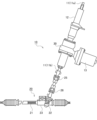
- FIG. 1 is a schematic diagram showing the configuration of an electric power steering device to which a plastic gear according to a first embodiment and a second embodiment of the present invention is applied.
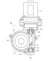
- FIG. 2 is a partial cross-sectional view showing a reduction gear mechanism of the electric power steering device shown in FIG.
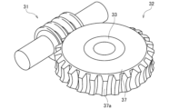
- FIG. 3 is a perspective view showing the worm gear and the worm wheel that constitute the reduction gear mechanism.
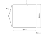
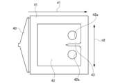
- FIG. 4 is a schematic diagram showing a method for forming a plate material for preparing a test piece in Test 1 and Test 2.
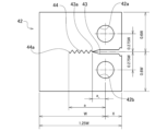
- FIG. 5 is a plan view showing examples of the shapes and sizes of test pieces in Test 1 and Test 2.
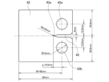
- FIG. 6 is a schematic diagram showing positions from which test pieces were taken from the plate material in Tests 1 and 2.
- FIG. 1 is a schematic diagram showing the configuration of an electric power steering device to which a plastic gear according to a first embodiment and a second embodiment of the present invention is applied.
- FIG. 2 is a partial cross-sectional view showing a reduction gear mechanism of the electric power steering
- FIG. 7 is a plan view showing the specific sizes of the test pieces in Test 1 and Test 2.
- FIG. 8 is a graph showing the results of Test 1, in which the vertical axis represents the crack growth rate and the horizontal axis represents the stress intensity factor range ⁇ K.
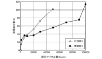
- FIG. 9 is a graph showing the results of Test 1, in which the vertical axis indicates the amount of tooth thickness reduction and the horizontal axis indicates the number of durability cycles, showing the results of the durability test for Example 1 and Comparative Example 1.
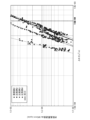
- FIG. 10 is a graph showing the results of Test 2, in which the vertical axis represents the crack growth rate and the horizontal axis represents the stress intensity factor range ⁇ K divided by the Young's modulus E of the resin material ( ⁇ K/E).
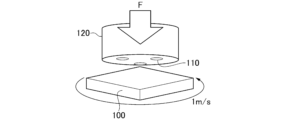
- FIG. 11 is a schematic diagram showing the configuration of an apparatus for carrying out the ball-on-disk friction and wear test of Test 2.
- FIG. 12 is a graph showing the results of the ball-on-disk friction and wear test of Test 2.
- FIG. 1 is a schematic diagram showing an electric power steering device to which a plastic gear according to the first embodiment is applied.
- a steering shaft 11 is composed of an upper steering shaft (hereinafter referred to as "upper shaft 11a") and a lower steering shaft (hereinafter referred to as “lower shaft 11b").
- the steering shaft 11 is supported inside a column housing 12 so as to be rotatable about its axis, and the column housing 12 is fixed at a predetermined position inside the vehicle cabin with its lower portion inclined toward the front of the vehicle.
- a steering wheel (not shown) is fixed to the upper end of the upper shaft 11a.
- the steering torque generated in the upper shaft 11a and the lower shaft 11b by the driver's operation of the steering wheel is detected by a torque sensor (not shown), and the output of the electric motor 13 is controlled based on the detected steering torque signal.
- the rotation of the electric motor 13 is transmitted to the lower shaft 11b via the reduction gear mechanism 30.
- the steering shaft 11 is connected to the rack and pinion type motion conversion mechanism 20 via universal joints 25 and 26.
- the rack and pinion type motion conversion mechanism 20 is arranged substantially horizontally in the engine room at the front of the vehicle with its longitudinal direction aligned with the left-right direction of the vehicle, and is composed of a rack shaft 21 that is movable in the axial direction, a pinion shaft 22, and a cylindrical rack shaft case 23 that supports the rack shaft 21 and the pinion shaft 22.
- the pinion shaft 22 is supported at an angle to the axis of the rack shaft 21, and includes a pinion with teeth that mesh with the teeth of the rack shaft 21.
- FIG. 2 is a partial cross-sectional view showing the reduction gear mechanism 30 of the electric power steering device 10 shown in FIG. 1.
- FIG. 3 is a perspective view showing the worm gear 31 and worm wheel 32 that constitute the reduction gear mechanism 30.
- FIG. 3 shows the state in which the worm wheel 32 is engaged with the worm gear 31.
- the worm gear 31 is made of, for example, metal, and has worm shafts 31a, 31b formed integrally at both ends.
- the worm shaft 31b closer to the electric motor 13 is splined or serrated and connected to the drive shaft 13a of the electric motor 13, so that it rotates integrally with the drive shaft 13a of the electric motor 13.
- the worm shafts 31a, 31b are rotatably supported by the gear case 36 via bearings 35a, 35b.
- the worm wheel 32 has a metal core 33 and a resin gear tooth portion 37 provided radially outside the core 33.
- Gear teeth 37a that mesh with the worm gear 31 are formed on the radial outer circumferential surface of the gear tooth portion 37.
- the gear tooth portion 37 is made of a resin material with an appropriately selected fatigue crack growth rate da/dN.
- the fatigue crack growth rate da/dN is measured in accordance with ASTM E647, and when the crack growth rate is plotted on a log-log graph with the vertical axis representing the crack growth rate and the horizontal axis representing the stress intensity factor range ⁇ K, and a relational expression is derived using Paris's law, a resin material is used in which the fatigue crack growth rate da/dN (mm/cycle) calculated by the above relational expression at any ⁇ K is equal to or less than the value A calculated by the following formula (1):
- ⁇ K is a value calculated by the following formula (2), and ⁇ , ⁇ P, B, W, a, N, P max and P min are as follows:
- the gear tooth portion 37 is made of a resin material whose crack growth rate is equal to or less than the value A calculated by formula (1), so that the progression of peeling is sufficiently suppressed and the durability of the worm wheel 32 can be improved.
- thermoplastic resin As the base material of the resin material constituting the gear teeth portion 37, and it is more preferable that the resin material contains reinforcing fibers.
- thermoplastic resins include polyamide-based resins, polyester-based resins, polyacetal-based resins, polycarbonate-based resins, polyacrylic-based resins, polyphenylene ether-based resins, polyarylate-based resins, polysulfone-based resins, polyphenylene sulfide-based resins, polyethersulfone-based resins, polyketone-based resins, polyphenylene ether ketone-based resins, polyamideimide-based resins, etc.
- thermoplastic resins it is preferable to use polyamide-based resins from the viewpoints of heat resistance, moldability, and mechanical strength, and it is particularly preferable to use polyamide 66 (PA66).
- the number average molecular weight Mn of the thermoplastic resin used as the resin material is preferably high in order to improve durability. Therefore, the number average molecular weight Mn of the thermoplastic resin is preferably 30,000 or more, and more preferably 32,000 or more.
- the number average molecular weight Mn of the thermoplastic resin is 60,000 or less.
- the number average molecular weight Mn of the thermoplastic resin is 50,000 or less, and even more preferable that it is 38,000 or less.
- the method and conditions for measuring the number average molecular weight Mn of the thermoplastic resin are as follows. Measurement method: GPC (gel permeation chromatography) Eluent: hexafluoroisopropanol (HEIP) ⁇ Standard material: Polymethyl methacrylate (PMMA) Injection volume: 10 ⁇ L ⁇ Flow rate: 0.3mL/min Sample concentration: 1 mg/mL of resin Column temperature: 45°C
- the resin material constituting the gear tooth portion 37 contains reinforcing fibers.
- the mechanical strength of the gear tooth portion 37 can be improved.
- reinforcing fibers include glass fibers, carbon fibers, aramid fibers, and whiskers such as potassium titanate and silicon carbide. Of these reinforcing fibers, it is more preferable to use glass fibers in terms of the balance between cost and reinforcing effect.
- the reinforcing fibers are not limited to one type, and the resin material may contain multiple types of reinforcing fibers.
- the average fiber diameter of the reinforcing fibers is preferably 8 ⁇ m or less.
- the average fiber diameter of the reinforcing fibers is preferably 6 ⁇ m or more.
- the average fiber diameter of the reinforcing fibers can be obtained, for example, by measuring the fiber diameters of 100 random reinforcing fibers by observation with a scanning electron microscope (SEM) and calculating the average of these diameters.
- the content of the reinforcing fibers in the resin material is preferably 15% by mass or more, more preferably 20% by mass or more, based on the total mass of the resin material.
- the content of the reinforcing fibers in the resin material is preferably 35% by mass or less, more preferably 30% by mass or less, based on the total mass of the resin material.
- the resin material may contain, in addition to the above-mentioned thermoplastic resin and reinforcing fiber, at least one of an iodide-based heat stabilizer, a phenol-based antioxidant, and an amine-based antioxidant in order to prevent deterioration due to heat during molding and use.
- the above embodiment shows an example in which a plastic gear is used as a worm wheel in a steering device, but the present invention is not limited to this, and the plastic gear according to the present invention can be used in various other devices.
- the method of manufacturing the resin gear is not particularly limited as long as the resin material constituting the teeth portion is selected as described above.
- a method of manufacturing a worm wheel will be described below with reference to FIG.
- the worm wheel 32 is obtained by insert molding, in which a metal core 33 is inserted into a mold, and then a resin composition for forming the resin material is injected.
- the molded product obtained by injection molding may be machined to improve the meshing and contact condition with the worm gear 31.
- the surface roughness of the worm wheel 32 becomes too large due to machining, there is a concern that noise reduction and durability may deteriorate. Therefore, even when machining, it is preferable to keep the surface roughness as small as possible.
- the arithmetic mean roughness (Ra) of the surface of the gear teeth 37a is 3.2 ⁇ m or less.
- the metal core 33 is not particularly limited, but from the viewpoint of mechanical strength, it is preferable to use carbon steel, aluminum or an aluminum alloy, or magnesium or a magnesium alloy.
- Test 1 will be used to provide a more detailed explanation of the plastic gear according to embodiment 1.
- Test 1 Measurement of crack growth rate (preparation of test pieces made of resin material)
- a resin composition was prepared by mixing polyamide 66 having a number average molecular weight Mn of 35,000 and glass fiber having an average fiber diameter of 6 ⁇ m, and the resin composition was injection molded to produce a test piece made of the resin material of Example 1.
- a resin composition was prepared by mixing polyamide 66 having a number average molecular weight Mn of 26,000 and glass fiber having an average fiber diameter of 6 ⁇ m, and the resin composition was injection molded to produce a test piece made of the resin material of Comparative Example 1. In each test piece, the content of polyamide 66 was 75 mass% and the content of glass fiber was 25 mass% relative to the total mass of the resin composition.
- Figure 4 is a schematic diagram showing the molding method for the plate material used to prepare the test specimens. As shown in Figure 4, first, a fan gate 40 was used as a mold to mold the plate material 41, which is 3 mm thick, 80 mm wide, and 80 mm long, by injection molding, so that the orientation of the glass fibers in the plate material would be as uniform as possible.
- Figure 5 is a plan view showing an example of the shape and size of the test piece.
- Figure 6 is a schematic diagram showing the position where the test piece is taken from the plate material.
- CT test piece a compact test piece with a shape conforming to ASTM E647 was used.
- Test piece 42 has a notch 43 extending inward from the center of one side, and circular holes 42a, 42b are provided on both sides of notch 43. When the two holes 42a, 42b are pulled in a direction away from each other, the length of the crack formed from the tip of notch 43 in the direction in which notch 43 extends is measured, and the crack growth rate is measured.
- W represents the length (test specimen width) from the center of holes 42a, 42b to the side opposite to the side on which notch 43 is formed
- a n represents the length (notch length) from tip 43a of notch 43 to the line connecting the center of hole 42a and the center of hole 42b
- a represents the length (crack length) from tip 44a of crack 44 to the line connecting the center of hole 42a and the center of hole 42b.
- the test piece width W was 48 mm
- the notch length an was 9.6 mm
- the diameter of the holes 42a, 42b was 12 mm
- the distance from the center of the holes 42a, 42b to the notch 43 was 13.2 mm.
- the distance from the end faces of the test piece on both sides of the notch 43 to the notch 43 was 28.8 mm
- the distance from the side where the notch 43 was formed to the opposite side was 60 mm
- the width of the notch 43 was 3 mm.
- the tip 43a of the notch 43 was subjected to R processing with a diameter of 0.25 mm.
- a crack of 0.5 mm was introduced into the tip 43a of the notch 43 with a razor.
- the crack growth rate was measured for the test pieces 42 of the invention example 1 and the comparative example 1 obtained as described above.
- the crack growth rate was measured using an Instron 8802 hydraulic servo test system.
- the crack length a was measured by a compliance method using an Instron clip gauge (model number 2670-120). Specifically, the test piece 42 was attached to a measurement jig by passing a pin through the holes 42a and 42b of the test piece 42, and a load was repeatedly applied in the servo test system in the direction in which the holes 42a and 42b were separated from each other.
- test conditions are as follows. Frequency: 10 Hz, sine wave Stress ratio (R): 0.1 Load range ( ⁇ P): constant Temperature: room temperature Maximum load (P max ): 460 N, minimum load (P min ): 46 N for Example 1 Comparative Example 1: Maximum load (P max ): 360 N, Minimum load (P min ): 36 N
- Example 1 The reason why the load conditions are different between Example 1 and Comparative Example 1 is that in the sample of Example 1, cracks did not grow under the conditions of P max : 360N, P min : 36N.
- Fig. 8 is a graph showing the crack growth rates of Example 1 and Comparative Example 1 in a double logarithmic graph, with the crack growth rate on the vertical axis and the stress intensity factor range ⁇ K on the horizontal axis. Based on these results, the following relational expression was derived using Paris's law. Note that Fig. 8 shows only the measurement results in the linear region where Paris's law holds, i.e., only data that is subject to linear approximation by Paris's law, and the relational expression shown below is an approximation expression for the crack growth rate of each test piece shown in Fig. 8.
- the formula (1) defined in the present invention is shown by a thick solid line in FIG. 8.
- the value A obtained by the formula (1) is shown on the vertical axis.
- ⁇ K is a value calculated by the following formula (2), and ⁇ , ⁇ P, B, W, a, N, P max and P min are as follows:
- Worm wheel durability test (creation of worm wheel and worm) To prepare the worm wheels of Example 1 and Comparative Example 1, the same resin composition as the test specimen for the above crack growth rate was prepared. Next, the worm wheels of Example 1 and Comparative Example 1 were prepared by insert molding in which the resin composition was injected into a metal mold with a metal core placed in the mold. The dimensions of each worm wheel were adjusted by machining to improve the meshing with the worm. In addition, a steel worm material was prepared, hardened by heat treatment, and then ground to prepare the worm.
- the obtained worm wheels and worms were combined to carry out a durability test of the worm wheels.
- the worm wheel was rotated in a predetermined direction so that a torque of 100 N ⁇ m was generated on the worm wheel shaft, and then the worm wheel was rotated in the reverse direction so that a similar torque was generated, forming one cycle.
- the reduction in tooth thickness due to damage to the tooth surface was calculated.
- the test machine used was equipped with a mechanism that displaces the worm to the worm wheel side by applying elasticity to eliminate backlash due to the reduction in tooth surface, and the reduction in tooth thickness was calculated from the amount of displacement.
- Grease was placed between the worm and the worm wheel to ensure lubrication.
- Figure 9 is a graph showing the durability test results for Example 1 and Comparative Example 1, with the vertical axis representing the amount of tooth thickness reduction and the horizontal axis representing the number of durability cycles. Note that the amount of tooth thickness reduction is expressed as a percentage, with the amount of tooth thickness reduction at the time when the worm wheel of Comparative Example 1 reached its usage limit being taken as 100%.
- the crack growth rate obtained using the approximation equation derived from the test piece made of the resin material of Example 1 was equal to or less than value A calculated using equation (1) at any ⁇ K, as shown by the thick solid line in Figure 8, and as a result, peeling was suppressed.
- the worm wheel of Example 1 showed a tooth thickness reduction of about 80% even after 90,000 cycles of operation, suppressing damage to the tooth surface and improving durability.
- the inventors measured the fatigue crack growth rate da/dN of the resin material in accordance with ASTM E647 by dividing and normalizing the stress intensity factor range ⁇ K obtained in embodiment 1 by the Young's modulus E of the resin material constituting the gear tooth portion 37, and found that when the crack growth rate is plotted on a double logarithmic graph with the crack growth rate on the vertical axis and the value ( ⁇ K/E) obtained by dividing the stress intensity factor range ⁇ K by the Young's modulus E of the resin material on the horizontal axis, a higher correlation can be obtained between ⁇ K /E and the fatigue crack growth rate da/dN if the fatigue crack growth rate da/dN (mm/cycle) calculated by the above relational equation is equal to or less than value A calculated by the following equation (3) in the range of ⁇ K/E ⁇ 7 ⁇ 10 ⁇ 4 [ ⁇ m]:
- ⁇ K can be calculated in the same manner as in formula (2) of embodiment 1.
- Young's modulus E can be calculated by the compliance method described in embodiment 1, and can be measured by changing the load and measuring compliance ⁇ according to the following formula (4) using the least squares method.
- V 0 in formula (4) is the opening displacement of the clip gauge.
- Test 2 clearly explains the relationship between ⁇ K/E and the fatigue crack growth rate da/dN.
- Test 2 1. Measurement of crack growth rate (preparation of test pieces made of resin material) A resin composition was prepared by mixing 75% by mass of polyamide 66 having a number average molecular weight Mn of 35,000 and 25% by mass of glass fiber having an average fiber diameter of 6 ⁇ m, and the resin composition was injection molded to produce a test piece made of the resin material of Example 2.
- a resin composition was prepared by mixing 75% by mass of polyamide 66 having a number average molecular weight Mn of 26,000 and 25% by mass of glass fibers having an average fiber diameter of 6 ⁇ m, and a test piece made of the resin material of Comparative Example 2 was prepared in the same manner.
- a resin composition (“KyronMAX (registered trademark) S-2220" manufactured by Mitsubishi Chemical Advanced Materials Corporation) containing 80% by mass of polyamide 66 and 20% by mass of carbon fiber was prepared, and a test piece made of the resin material of Comparative Example 3 was prepared in the same manner.
- a resin composition (“Genestar (registered trademark) G1300A” manufactured by Kuraray Co., Ltd.) containing 70% by mass of polyamide 9T and 30% by mass of glass fiber was prepared, and test pieces made of the resin material of Comparative Example 4 were prepared in the same manner.
- Test pieces of the same shape were prepared in the same manner as in Test 1, and the test was performed using an Instron E10kN electromagnetic fatigue tester.
- the crack length a was measured by the compliance method using an Instron clip gauge (model number 2670-130).
- the specific loads were a maximum load (P max ) of 360N and a minimum load (P min ) of 36N.
- P max maximum load
- P min minimum load
- test conditions are as follows. Frequency: 10 Hz, sine wave Stress ratio (R): 0.1 Load range ( ⁇ P): constant Temperature: room temperature Maximum load (P max ): 450 N, minimum load (P min ): 45 N for Example 2 Comparative Example 2: Maximum load (P max ): 400N, Minimum load (P min ): 40N Comparative Example 3: Maximum load (P max ): 650N, Minimum load (P min ): 65N Comparative Example 4: Maximum load (P max ): 360 N, Minimum load (P min ): 36 N
- Figure 10 shows the results of Test 2, and is a graph showing the measurement results of the crack growth rate, where the vertical axis is the crack growth rate and the horizontal axis is the value ( ⁇ K/E) obtained by dividing the stress intensity factor range ⁇ K by the Young's modulus E of the resin material, and is shown in a double logarithmic graph. From the straight line portions of each graph in Figure 10, the crack growth rate of the material is as follows:
- Example 2 has a lower crack growth rate value at any ⁇ K/E in the range of ⁇ K/E ⁇ 7 ⁇ 10 ⁇ 4 [ ⁇ m] compared to Comparative Examples 2, 3, and 4.
- equation (3) defined in the present invention is shown by a thick solid line in FIG. 10.
- the value A obtained by equation (3) is shown on the vertical axis.
- FIG. 11 shows a schematic diagram showing the configuration of an apparatus for performing a ball-on-disk friction and wear test.
- a jig 120 having three equally spaced 1 ⁇ 4-inch carbon steel balls 110 was placed on the surface of the sample 100, and the jig 120 was continuously rotated at a peripheral speed of 1 m/s under a load (F) of 40 N.
- F load
- the "peeling life ratio" is approximately 0.7 times that of Example 2 in Comparative Example 2, approximately 0.3 times that of Comparative Example 3, and approximately 0.1 times that of Example 2 in Comparative Example 4. It can be seen that the application of a material with a low crack growth rate suppresses peeling, and when applied to plastic gears, the durability is improved.
- Resin Compositions of Examples 1 and 2 Resin compositions obtained by mixing polyamide 66 having a number average molecular weight Mn of 35,000 and glass fibers having an average fiber diameter of 6 ⁇ m.
- Resin compositions of Comparative Examples 1 and 2 Resin compositions obtained by mixing polyamide 66 having a number average molecular weight Mn of 26,000 and glass fibers having an average fiber diameter of 6 ⁇ m
Landscapes
- Engineering & Computer Science (AREA)
- General Engineering & Computer Science (AREA)
- Mechanical Engineering (AREA)
- Chemical & Material Sciences (AREA)
- Combustion & Propulsion (AREA)
- Transportation (AREA)
- Physics & Mathematics (AREA)
- Electromagnetism (AREA)
- Thermal Sciences (AREA)
- Gears, Cams (AREA)
Priority Applications (2)
| Application Number | Priority Date | Filing Date | Title |
|---|---|---|---|
| CN202480068640.8A CN122122411A (zh) | 2023-10-27 | 2024-10-25 | 树脂齿轮 |
| JP2025553445A JPWO2025089407A1 (cg-RX-API-DMAC7.html) | 2023-10-27 | 2024-10-25 |
Applications Claiming Priority (4)
| Application Number | Priority Date | Filing Date | Title |
|---|---|---|---|
| JP2023-184860 | 2023-10-27 | ||
| JP2023184860 | 2023-10-27 | ||
| JP2024179219 | 2024-10-11 | ||
| JP2024-179219 | 2024-10-11 |
Publications (1)
| Publication Number | Publication Date |
|---|---|
| WO2025089407A1 true WO2025089407A1 (ja) | 2025-05-01 |
Family
ID=95515787
Family Applications (1)
| Application Number | Title | Priority Date | Filing Date |
|---|---|---|---|
| PCT/JP2024/038175 Pending WO2025089407A1 (ja) | 2023-10-27 | 2024-10-25 | 樹脂ギヤ |
Country Status (3)
| Country | Link |
|---|---|
| JP (1) | JPWO2025089407A1 (cg-RX-API-DMAC7.html) |
| CN (1) | CN122122411A (cg-RX-API-DMAC7.html) |
| WO (1) | WO2025089407A1 (cg-RX-API-DMAC7.html) |
Citations (6)
| Publication number | Priority date | Publication date | Assignee | Title |
|---|---|---|---|---|
| JPH0841246A (ja) * | 1994-07-29 | 1996-02-13 | Bando Chem Ind Ltd | 樹脂組成物 |
| WO2004083015A1 (ja) | 2003-03-19 | 2004-09-30 | Nsk Ltd. | 電動パワーステアリング装置及びそれに使用する樹脂歯車 |
| WO2006054774A1 (ja) * | 2004-11-22 | 2006-05-26 | Ube Industries, Ltd. | ガラス繊維含有ポリアミド樹脂組成物 |
| JP2013155788A (ja) | 2012-01-27 | 2013-08-15 | Showa Corp | 電動パワーステアリング装置用ギヤ |
| JP2020108958A (ja) | 2018-04-23 | 2020-07-16 | 旭化成株式会社 | セルロース含有ギヤ |
| JP2024179219A (ja) | 2023-06-14 | 2024-12-26 | 東芝エレベータ株式会社 | エレベータ制御装置、エレベータ制御方法およびプログラム |
-
2024
- 2024-10-25 JP JP2025553445A patent/JPWO2025089407A1/ja active Pending
- 2024-10-25 WO PCT/JP2024/038175 patent/WO2025089407A1/ja active Pending
- 2024-10-25 CN CN202480068640.8A patent/CN122122411A/zh active Pending
Patent Citations (6)
| Publication number | Priority date | Publication date | Assignee | Title |
|---|---|---|---|---|
| JPH0841246A (ja) * | 1994-07-29 | 1996-02-13 | Bando Chem Ind Ltd | 樹脂組成物 |
| WO2004083015A1 (ja) | 2003-03-19 | 2004-09-30 | Nsk Ltd. | 電動パワーステアリング装置及びそれに使用する樹脂歯車 |
| WO2006054774A1 (ja) * | 2004-11-22 | 2006-05-26 | Ube Industries, Ltd. | ガラス繊維含有ポリアミド樹脂組成物 |
| JP2013155788A (ja) | 2012-01-27 | 2013-08-15 | Showa Corp | 電動パワーステアリング装置用ギヤ |
| JP2020108958A (ja) | 2018-04-23 | 2020-07-16 | 旭化成株式会社 | セルロース含有ギヤ |
| JP2024179219A (ja) | 2023-06-14 | 2024-12-26 | 東芝エレベータ株式会社 | エレベータ制御装置、エレベータ制御方法およびプログラム |
Also Published As
| Publication number | Publication date |
|---|---|
| CN122122411A (zh) | 2026-05-29 |
| JPWO2025089407A1 (cg-RX-API-DMAC7.html) | 2025-05-01 |
Similar Documents
| Publication | Publication Date | Title |
|---|---|---|
| Mao et al. | The wear resistance improvement of fibre reinforced polymer composite gears | |
| Düzcükoğlu | Study on development of polyamide gears for improvement of load-carrying capacity | |
| Kunishima et al. | Effects of glass fiber properties and polymer molecular mass on the mechanical and tribological properties of a polyamide-66-based composite in contact with carbon steel under grease lubrication | |
| ZA200100523B (en) | Bearing material. | |
| CN111919042A (zh) | 树脂制保持器以及滚动轴承 | |
| US5697709A (en) | Dynamic pressure type bearing device | |
| CN103517950A (zh) | 用于经润滑的滑动系统的滑动元件 | |
| Goriparthi et al. | Performance evaluation of composite gears composed of POM, CNTs, and PTFE | |
| CN1578811A (zh) | 滑动零件和精密零件及使用它们的钟表和电子设备 | |
| JP2017214520A (ja) | 摩耗低減方法および高面圧摺動部材 | |
| Karupaiah et al. | Performance evaluation of 3D-printed ABS and carbon fiber-reinforced ABS polymeric spur gears | |
| EP1803775B1 (en) | Sliding member for chain system, chain guide, chain tensioner and chain system | |
| JP2003139220A (ja) | ウォームホイール及びその製造方法 | |
| US20040142181A1 (en) | PTFE/polyphenylene sulphide bearing material and method of manufacture | |
| JP2005240940A (ja) | 樹脂歯車 | |
| Düzcükoğlu et al. | The use of cooling holes to decrease the amount of thermal damage on a plastic gear tooth | |
| JPH04267131A (ja) | ギヤの結合方法 | |
| EP1705403A2 (en) | Electrically driven linear actuator | |
| WO2019189779A1 (ja) | 樹脂製保持器及び転がり軸受 | |
| JP2016200184A (ja) | 摺動部材および摺動部材の製造方法 | |
| JP2004314916A (ja) | 電動パワーステアリング装置 | |
| JPWO2002053446A1 (ja) | シールリングおよびこれを備えてなるパワーステアリングのバルブ装置 | |
| JP2013095221A (ja) | 電動パワーステアリング装置用ギヤ | |
| JP2016064714A (ja) | 電動パワーステアリング装置用減速ギヤ及び電動パワーステアリング装置 | |
| JP2009202754A (ja) | 電動パワーステアリング装置用減速ギヤ機構 |
Legal Events
| Date | Code | Title | Description |
|---|---|---|---|
| 121 | Ep: the epo has been informed by wipo that ep was designated in this application |
Ref document number: 24882515 Country of ref document: EP Kind code of ref document: A1 |
|
| ENP | Entry into the national phase |
Ref document number: 2025553445 Country of ref document: JP Kind code of ref document: A |
|
| NENP | Non-entry into the national phase |
Ref country code: DE |