WO2025088680A1 - レーザ装置およびレーザ加工装置 - Google Patents
レーザ装置およびレーザ加工装置 Download PDFInfo
- Publication number
- WO2025088680A1 WO2025088680A1 PCT/JP2023/038269 JP2023038269W WO2025088680A1 WO 2025088680 A1 WO2025088680 A1 WO 2025088680A1 JP 2023038269 W JP2023038269 W JP 2023038269W WO 2025088680 A1 WO2025088680 A1 WO 2025088680A1
- Authority
- WO
- WIPO (PCT)
- Prior art keywords
- pulsed light
- laser device
- generating unit
- aberration
- light
- Prior art date
- Legal status (The legal status is an assumption and is not a legal conclusion. Google has not performed a legal analysis and makes no representation as to the accuracy of the status listed.)
- Pending
Links
Images





Classifications
-
- H—ELECTRICITY
- H01—ELECTRIC ELEMENTS
- H01S—DEVICES USING THE PROCESS OF LIGHT AMPLIFICATION BY STIMULATED EMISSION OF RADIATION [LASER] TO AMPLIFY OR GENERATE LIGHT; DEVICES USING STIMULATED EMISSION OF ELECTROMAGNETIC RADIATION IN WAVE RANGES OTHER THAN OPTICAL
- H01S3/00—Lasers, i.e. devices using stimulated emission of electromagnetic radiation in the infrared, visible or ultraviolet wave range
- H01S3/005—Optical devices external to the laser cavity, specially adapted for lasers, e.g. for homogenisation of the beam or for manipulating laser pulses, e.g. pulse shaping
- H01S3/0085—Modulating the output, i.e. the laser beam is modulated outside the laser cavity
-
- H—ELECTRICITY
- H01—ELECTRIC ELEMENTS
- H01S—DEVICES USING THE PROCESS OF LIGHT AMPLIFICATION BY STIMULATED EMISSION OF RADIATION [LASER] TO AMPLIFY OR GENERATE LIGHT; DEVICES USING STIMULATED EMISSION OF ELECTROMAGNETIC RADIATION IN WAVE RANGES OTHER THAN OPTICAL
- H01S3/00—Lasers, i.e. devices using stimulated emission of electromagnetic radiation in the infrared, visible or ultraviolet wave range
- H01S3/09—Processes or apparatus for excitation, e.g. pumping
- H01S3/091—Processes or apparatus for excitation, e.g. pumping using optical pumping
- H01S3/094—Processes or apparatus for excitation, e.g. pumping using optical pumping by coherent light
- H01S3/094076—Pulsed or modulated pumping
-
- H—ELECTRICITY
- H01—ELECTRIC ELEMENTS
- H01S—DEVICES USING THE PROCESS OF LIGHT AMPLIFICATION BY STIMULATED EMISSION OF RADIATION [LASER] TO AMPLIFY OR GENERATE LIGHT; DEVICES USING STIMULATED EMISSION OF ELECTROMAGNETIC RADIATION IN WAVE RANGES OTHER THAN OPTICAL
- H01S3/00—Lasers, i.e. devices using stimulated emission of electromagnetic radiation in the infrared, visible or ultraviolet wave range
- H01S3/09—Processes or apparatus for excitation, e.g. pumping
- H01S3/091—Processes or apparatus for excitation, e.g. pumping using optical pumping
- H01S3/094—Processes or apparatus for excitation, e.g. pumping using optical pumping by coherent light
- H01S3/0941—Processes or apparatus for excitation, e.g. pumping using optical pumping by coherent light of a laser diode
- H01S3/09415—Processes or apparatus for excitation, e.g. pumping using optical pumping by coherent light of a laser diode the pumping beam being parallel to the lasing mode of the pumped medium, e.g. end-pumping
-
- H—ELECTRICITY
- H01—ELECTRIC ELEMENTS
- H01S—DEVICES USING THE PROCESS OF LIGHT AMPLIFICATION BY STIMULATED EMISSION OF RADIATION [LASER] TO AMPLIFY OR GENERATE LIGHT; DEVICES USING STIMULATED EMISSION OF ELECTROMAGNETIC RADIATION IN WAVE RANGES OTHER THAN OPTICAL
- H01S3/00—Lasers, i.e. devices using stimulated emission of electromagnetic radiation in the infrared, visible or ultraviolet wave range
- H01S3/10—Controlling the intensity, frequency, phase, polarisation or direction of the emitted radiation, e.g. switching, gating, modulating or demodulating
-
- H—ELECTRICITY
- H01—ELECTRIC ELEMENTS
- H01S—DEVICES USING THE PROCESS OF LIGHT AMPLIFICATION BY STIMULATED EMISSION OF RADIATION [LASER] TO AMPLIFY OR GENERATE LIGHT; DEVICES USING STIMULATED EMISSION OF ELECTROMAGNETIC RADIATION IN WAVE RANGES OTHER THAN OPTICAL
- H01S3/00—Lasers, i.e. devices using stimulated emission of electromagnetic radiation in the infrared, visible or ultraviolet wave range
- H01S3/10—Controlling the intensity, frequency, phase, polarisation or direction of the emitted radiation, e.g. switching, gating, modulating or demodulating
- H01S3/10007—Controlling the intensity, frequency, phase, polarisation or direction of the emitted radiation, e.g. switching, gating, modulating or demodulating in optical amplifiers
- H01S3/1001—Controlling the intensity, frequency, phase, polarisation or direction of the emitted radiation, e.g. switching, gating, modulating or demodulating in optical amplifiers by controlling the optical pumping
-
- H—ELECTRICITY
- H01—ELECTRIC ELEMENTS
- H01S—DEVICES USING THE PROCESS OF LIGHT AMPLIFICATION BY STIMULATED EMISSION OF RADIATION [LASER] TO AMPLIFY OR GENERATE LIGHT; DEVICES USING STIMULATED EMISSION OF ELECTROMAGNETIC RADIATION IN WAVE RANGES OTHER THAN OPTICAL
- H01S3/00—Lasers, i.e. devices using stimulated emission of electromagnetic radiation in the infrared, visible or ultraviolet wave range
- H01S3/10—Controlling the intensity, frequency, phase, polarisation or direction of the emitted radiation, e.g. switching, gating, modulating or demodulating
- H01S3/10007—Controlling the intensity, frequency, phase, polarisation or direction of the emitted radiation, e.g. switching, gating, modulating or demodulating in optical amplifiers
- H01S3/10023—Controlling the intensity, frequency, phase, polarisation or direction of the emitted radiation, e.g. switching, gating, modulating or demodulating in optical amplifiers by functional association of additional optical elements, e.g. filters, gratings, reflectors
- H01S3/1003—Controlling the intensity, frequency, phase, polarisation or direction of the emitted radiation, e.g. switching, gating, modulating or demodulating in optical amplifiers by functional association of additional optical elements, e.g. filters, gratings, reflectors tunable optical elements, e.g. acousto-optic filters, tunable gratings
-
- H—ELECTRICITY
- H01—ELECTRIC ELEMENTS
- H01S—DEVICES USING THE PROCESS OF LIGHT AMPLIFICATION BY STIMULATED EMISSION OF RADIATION [LASER] TO AMPLIFY OR GENERATE LIGHT; DEVICES USING STIMULATED EMISSION OF ELECTROMAGNETIC RADIATION IN WAVE RANGES OTHER THAN OPTICAL
- H01S3/00—Lasers, i.e. devices using stimulated emission of electromagnetic radiation in the infrared, visible or ultraviolet wave range
- H01S3/23—Arrangements of two or more lasers not provided for in groups H01S3/02 - H01S3/22, e.g. tandem arrangements of separate active media
- H01S3/2308—Amplifier arrangements, e.g. MOPA
- H01S3/2316—Cascaded amplifiers
-
- H—ELECTRICITY
- H01—ELECTRIC ELEMENTS
- H01S—DEVICES USING THE PROCESS OF LIGHT AMPLIFICATION BY STIMULATED EMISSION OF RADIATION [LASER] TO AMPLIFY OR GENERATE LIGHT; DEVICES USING STIMULATED EMISSION OF ELECTROMAGNETIC RADIATION IN WAVE RANGES OTHER THAN OPTICAL
- H01S3/00—Lasers, i.e. devices using stimulated emission of electromagnetic radiation in the infrared, visible or ultraviolet wave range
- H01S3/23—Arrangements of two or more lasers not provided for in groups H01S3/02 - H01S3/22, e.g. tandem arrangements of separate active media
- H01S3/2375—Hybrid lasers
-
- H—ELECTRICITY
- H01—ELECTRIC ELEMENTS
- H01S—DEVICES USING THE PROCESS OF LIGHT AMPLIFICATION BY STIMULATED EMISSION OF RADIATION [LASER] TO AMPLIFY OR GENERATE LIGHT; DEVICES USING STIMULATED EMISSION OF ELECTROMAGNETIC RADIATION IN WAVE RANGES OTHER THAN OPTICAL
- H01S5/00—Semiconductor lasers
- H01S5/10—Construction or shape of the optical resonator, e.g. extended or external cavity, coupled cavities, bent-guide, varying width, thickness or composition of the active region
- H01S5/12—Construction or shape of the optical resonator, e.g. extended or external cavity, coupled cavities, bent-guide, varying width, thickness or composition of the active region the resonator having a periodic structure, e.g. in distributed feedback [DFB] lasers
Definitions
- This disclosure relates to a laser device that emits laser light used in laser processing and a laser processing device.
- MOPA Master Oscillator Power Amplifier
- the short pulse light output from a seed light source is amplified by a solid-state amplifier and output.
- Advantages of the MOPA method include the ease of controlling the repetition frequency and the ability to increase output by increasing the number of stages in the solid-state amplifier.
- the peak power of the pulsed light output changes depending on the repetition frequency.
- the peak power changes, the impact of the nonlinear optical effect that occurs when the pulsed light passes through an optical element and a solid active medium changes.
- the beam propagation characteristics of the pulsed light after passing through a solid active medium change depending on the repetition frequency due to the optical Kerr effect, in which the refractive index of the medium changes depending on the intensity of the pulsed light.
- the beam quality of the pulsed light changes, the minimum focusing diameter and intensity distribution at the machining point change, making it difficult to maintain constant machining quality after changing the repetition frequency.
- Patent Document 1 discloses a laser light source device that includes a seed light source that outputs pulsed light using a gain switching method, a fiber amplifier that amplifies the pulsed light output from the seed light source, a solid-state amplifier that amplifies the pulsed light output from the fiber amplifier, and a nonlinear optical element that converts the wavelength of the pulsed light output from the solid-state amplifier.
- the configuration of the conventional laser light source device described above does not take into consideration the change in the beam propagation characteristics of the pulsed light after passing through the solid active medium due to the optical Kerr effect when the repetition frequency is changed.
- the configuration of the conventional laser light source device described above there was a problem in that the peak power of the pulsed light changes when the repetition frequency of the pulsed light output from the seed light source is changed, making it difficult to suppress the change in the beam propagation characteristics of the amplified pulsed light.
- the present disclosure has been made in consideration of the above, and aims to obtain a laser device that can suppress changes in the propagation characteristics of the amplified beam caused by changing the repetition frequency of the seed light source.
- the laser device disclosed herein comprises a seed light source that outputs pulsed light and is capable of controlling the repetition frequency of the pulsed light, an aberration generation unit that adds aberration due to the optical Kerr effect to the pulsed light, a beam shaping optical system that adjusts at least one of the beam diameter and intensity distribution of the pulsed light, a solid-state amplifier that amplifies the pulsed light and emits laser light, and a placement adjustment unit that can operate at least one of the aberration generation unit and the beam shaping optical system according to the repetition frequency of the pulsed light.
- the laser device disclosed herein has the advantage of being able to suppress changes in the propagation characteristics of the amplified beam caused by changes in the repetition frequency of the seed light source.
- FIG. 1 is a block diagram showing a schematic example of a configuration of a laser processing device including a laser device according to a first embodiment
- FIG. 1 is a diagram showing an example of a hardware configuration of a control unit of a laser device according to a first embodiment
- FIG. 13 is a schematic diagram showing another example of the configuration of the aberration generating unit in the laser device according to the first embodiment
- FIG. 1 shows an example of a simulation result of beam quality after a pulsed light passes through a solid-state active medium in a typical solid-state amplifier.
- FIG. 2 is a schematic diagram showing an example of the configuration of an aberration generating unit of the laser device according to the first embodiment;
- FIG. 1 is a block diagram showing a schematic example of a configuration of a laser processing device including a laser device according to a first embodiment
- FIG. 1 is a diagram showing an example of a hardware configuration of a control unit of a laser device according to a first embodiment
- FIG. 13 is a schematic diagram showing another example
- FIG. 13 is a schematic diagram showing another example of the configuration of the aberration generating unit of the laser device according to the first embodiment
- FIG. 2 is a schematic diagram showing an example of the configuration of a beam shaping optical system of the laser device according to the first embodiment
- FIG. 13 shows an example of the results of simulating the intensity distribution on the incident surface of a solid active medium by applying a beam shaping optical system to pulsed light that has passed through an aberration generating unit.
- FIG. 13 is a schematic diagram showing an example of the configuration of a laser processing device including a laser device according to a second embodiment;
- Embodiment 1. 1 is a block diagram showing a schematic example of a configuration of a laser processing apparatus including a laser device according to a first embodiment.
- the laser processing apparatus 1 includes a laser device 100 that outputs laser light, and a processing optical system 60 that focuses and irradiates the laser light output from the laser device 100 on an object 70.
- the laser device 100 is an apparatus that induces emission of laser light using a solid active medium 41.
- the laser device 100 can also output laser light of a desired wavelength using a wavelength conversion crystal 50.
- the laser processing apparatus 1 is an apparatus that processes an object 70 using laser light output from the laser device 100 using the solid active medium 41.
- the laser device 100 includes a seed light source 10, a control unit 11, an aberration generating unit 20, a placement adjustment unit 21, a beam shaping optical system 30, a placement adjustment unit 31, a solid-state amplifier 40, and a wavelength conversion crystal 50.
- the seed light source 10 outputs short pulse light, which is laser light with a pulse width of several tens of picoseconds or less.
- the short pulse light output from the seed light source 10 is laser light that is amplified in the solid active medium 41.
- the short pulse light output from the seed light source 10 is referred to as pulse light.
- the seed light source 10 is a gain switch-driven semiconductor laser, a mode-locked fiber laser oscillator, or a solid-state laser oscillator.
- the seed light source 10 may be a MOPA light source that is composed of a seed pulse light source that outputs pulse light and an amplifier that amplifies the pulse light.
- An example of the wavelength of the pulse light is 1064 nm.
- the control unit 11 controls various parameters such as the wavelength, average output, repetition frequency, and pulse width of the pulsed light output from the seed light source 10.
- the repetition frequency is the number of pulses generated per second at a constant period.
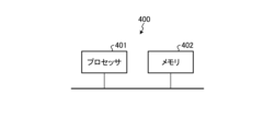
- FIG. 2 is a diagram showing an example of the hardware configuration of the control unit of the laser device according to embodiment 1.
- the control unit 11 can be realized by the control circuit 400 shown in FIG. 2, that is, the processor 401 and the memory 402.
- the processor 401 is a CPU (also called a central processing unit, processing unit, arithmetic unit, microprocessor, microcomputer, processor, or DSP (Digital Signal Processor)) or a system LSI (Large Scale Integration).
- the memory 402 is a RAM (Random Access Memory) or a ROM (Read Only Memory).
- control unit 11 The functions of the control unit 11 are realized by the processor 401 reading and executing a control program stored in the memory 402, which is a program for executing processing in the control unit 11. This control program can also be said to cause a computer to execute a method of emitting pulsed light from the seed light source 10 in the control unit 11.
- the control program executed by the control unit 11 has a modular configuration that modularizes the process of emitting pulsed light from the seed light source 10, and these are loaded onto the main storage device and generated on the main storage device.
- the memory 402 stores data to be set in the seed light source 10 when performing the pulsed light emission process.
- the memory 402 is also used as a temporary memory when the processor 401 executes various processes.
- the control program executed by the processor 401 may be provided as a computer program product in the form of an installable or executable file stored on a computer-readable storage medium.
- the control program executed by the processor 401 may also be provided to the control unit 11 of the laser device 100 via a network such as the Internet.
- the control unit 11 may also be realized by dedicated hardware. Also, some of the functions of the control unit 11 may be realized by dedicated hardware, and some may be realized by software or firmware.
- the aberration generating unit 20 transmits the pulsed light output from the seed light source 10, but at this time the pulsed light is phase-modulated by the optical Kerr effect.
- the aberration generating unit 20 adds aberration due to the optical Kerr effect to the pulsed light.
- the aberration generating unit 20 is composed of an optical Kerr medium, which is a material that has the optical Kerr effect.
- the optical Kerr effect is a phenomenon in which the refractive index of a medium that transmits laser light changes according to the intensity distribution of the high-intensity laser light that is transmitted through it.
- the optical Kerr medium is a medium whose refractive index changes according to the intensity distribution of the laser light that is transmitted through it.
- laser light has a Gaussian intensity distribution, so the refractive index distribution is Gaussian.
- the Gaussian refractive index distribution in the medium acts as a lens, and the laser is focused. This is called a Kerr lens. Since the refractive index distribution of the Kerr lens is Gaussian, aberration occurs. This causes the wavefront of the transmitted laser to become distorted, causing deterioration of the beam quality.
- the aberration generating unit 20 is configured to suppress reflection of the incoming pulsed light and the outgoing pulsed light.
- the aberration generating unit 20 has an anti-reflection coating for the wavelength of the pulsed light on the entrance surface and exit surface of the pulsed light.
- the entrance surface and the reflection surface of the aberration generating unit 20 may not be provided with an anti-reflection coating for the wavelength of the pulsed light.
- FIG. 3 is a diagram showing a schematic diagram of another example of the configuration of the aberration generating unit in the laser device according to the first embodiment. As shown in FIG.
- the aberration generating unit 20 may be configured such that the entrance surface 201 and the exit surface 202 of the pulsed light LP in the aberration generating unit 20 are non-coated, and the pulsed light LP is incident on the aberration generating unit 20 at a Brewster angle ⁇ Bi and the pulsed light LP is exited at a Brewster angle ⁇ Bo.
- the pulsed light LP enters and exits the aberration generating unit 20 at Brewster angles ⁇ Bi and ⁇ Bo, so the reflectance at the entrance surface 201 and the exit surface 202 can be reduced even without an anti-reflection coating.
- no anti-reflection coating is provided on the aberration generating unit 20, there is an advantage in that damage to the anti-reflection coating can be avoided.
- the placement adjustment unit 21 is a component that adjusts the placement of the aberration generation unit 20.
- the placement adjustment unit 21 is operated by a user of the laser processing device 1 or the laser device 100 in order to adjust the pulsed light so as not to significantly degrade the beam quality of the laser light output from the solid-state amplifier 40.
- the placement adjustment unit 21 corresponds to the second placement adjustment unit. Details of the placement adjustment unit 21 will be described later.
- the beam shaping optical system 30 adjusts at least one of the beam diameter and intensity distribution of the pulsed light that has been phase modulated by the aberration generating unit 20.
- the beam shaping optical system 30 has at least one optical element selected from the group consisting of a spherical lens and a curved mirror as its constituent elements.
- the pulsed light that has passed through the beam shaping optical system 30 is amplified by the solid-state amplifier 40.
- the placement adjustment unit 31 is a member that adjusts the placement of the beam shaping optical system 30.
- the placement adjustment unit 31 is operated by a user of the laser processing device 1 or the laser device 100 in order to adjust the pulsed light so as not to significantly degrade the beam quality of the laser light output from the solid-state amplifier 40 when the repetition frequency of the pulsed light is changed.
- the placement adjustment unit 31 corresponds to a first placement adjustment unit that moves components that are optical elements that make up the beam shaping optical system 30. Details of the placement adjustment unit 31 will be described later. Note that the placement adjustment unit 21 and the placement adjustment unit 31 correspond to a broader definition of a placement adjustment unit that can operate at least one of the aberration generation unit 20 and the beam shaping optical system 30 according to the repetition frequency of the pulsed light.
- the solid-state amplifier 40 amplifies the pulsed light output from the beam shaping optical system 30 and emits a laser beam.
- the solid-state amplifier 40 includes a solid-state active medium 41, an excitation light source 42, and a dichroic mirror 43.
- a solid-state active medium is a medium having a property of amplifying a laser beam by exciting the solid-state active medium at a determined wavelength, that is, a gain, in an example of a solid-state base material such as YAG (Yttrium Aluminum Garnet) or YVO4, and the like.
- YAG Yttrium Aluminum Garnet
- YVO4 YVO4
- a medium whose gain band includes the wavelength of the pulsed light emitted from the seed light source 10 is selected.
- the wavelength of the pulsed light emitted from the seed light source 10 is 1064 nm
- Nd:YVO 4 , Nd:YAG, or the like is preferably used for the solid-state active medium 41.
- the wavelength of the pulsed light emitted from the seed light source 10 is 1030 nm
- Yb:YAG, or the like is used for the solid-state active medium 41.
- the solid-state active medium 41 is end-pumped by the pumping light source 42.
- End-pumping is a method of pumping the solid-state active medium 41 by making the pumping light from the pumping light source 42 enter the solid-state active medium 41 in the same axial direction as the optical axis of the laser light emitted from the solid-state active medium 41.
- the incident direction of the pumping light from the pumping light source 42 to the solid-state active medium 41 is appropriately selected according to the shape of the solid-state active medium 41 or the beam propagation characteristics of the pumping light source 42 used.
- the pulsed light incident on the solid active medium 41 is amplified and emitted as a laser beam, which is a pulsed amplified light.
- the excitation light source 42 is a light source that outputs laser light for exciting the solid-state active medium 41.
- a semiconductor laser is preferably used for the excitation light source 42.
- the excitation light source 42 is often a fiber-coupled semiconductor laser.
- the wavelength of the laser light output from the excitation light source 42 is selected according to the absorption spectrum of the solid-state active medium 41. In one example, when the solid-state active medium 41 is Nd: YVO4 , laser light with wavelengths of 808 nm, 879 nm, 888 nm, and 914 nm is used.
- excitation by laser light with wavelengths of 879 nm, 888 nm, and 914 nm which is direct excitation, has the advantage of generating less heat due to quantum defects and reducing the temperature rise of the solid-state active medium 41 associated with excitation.
- the dichroic mirror 43 is provided to allow the pulsed light from the seed light source 10 and the excitation light from the excitation light source 42 to be incident on the same axis onto the solid active medium 41.
- the excitation light output from the excitation light source 42 is transmitted through or reflected by the dichroic mirror 43 and is incident on the solid active medium 41 on the same axis as the pulsed light.
- the dichroic mirror 43 is configured to transmit the pulsed light from the seed light source 10 and reflect the excitation light from the excitation light source 42.
- the wavelength conversion crystal 50 converts the wavelength of the pulsed amplified light.
- the wavelength conversion crystal 50 uses LiB 3 O 5 (Lithium Triborate: LBO), CsLiB 6 O 10 (Cesium Lithium Borate: CLBO), or ⁇ -BaB 2 O 4 (Barium Metaborate: BBO) crystal, and converts the wavelength to the second harmonic, third harmonic, or fourth harmonic by harmonic generation.
- the wavelength conversion crystal 50 is provided as necessary.
- the laser device 100 emits pulsed laser light with a wavelength determined by the wavelength conversion crystal 50.
- the processing optical system 60 forms an optical path to guide the pulsed amplified light emitted from the laser device 100 to the workpiece 70, and has optical elements that focus the pulsed amplified light at a desired position on the workpiece 70.
- the processing optical system 60 includes one or more lenses that adjust the beam diameter of the pulsed amplified light, a transmission mirror that transmits the pulsed amplified light, a galvanometer scanner that scans the pulsed amplified light, an f ⁇ lens that focuses the pulsed amplified light, and the like.
- the wavelength-converted pulsed amplified light is transmitted to the workpiece 70 by the processing optical system 60.
- Embodiment 1 is characterized in that it includes at least one of the placement adjustment unit 21 and the placement adjustment unit 31, which are placement adjustment units capable of operating at least one of the aberration generation unit 20 and the beam shaping optical system 30 according to the repetition frequency set in the seed light source 10.
- the placement adjustment unit 21 and the placement adjustment unit 31 are placement adjustment units capable of operating at least one of the aberration generation unit 20 and the beam shaping optical system 30 according to the repetition frequency set in the seed light source 10.
- the placement adjustment unit 21 and the placement adjustment unit 31 is operated by the user so as to adjust at least one of the placement of the aberration generation unit 20 and the placement of the beam shaping optical system 30.
- the aberration generating unit 20 applies a phase change to the pulsed light by the optical Kerr effect, generating aberration.
- the beam shaping optical system 30 utilizes the aberration generated by the aberration generating unit 20 to adjust at least one of the beam diameter and intensity distribution of the pulsed light in the solid active medium 41.
- n(r) the refractive index change due to the optical Kerr effect is expressed by the following formula (1):
- r represents the radial position of the pulse light, which is laser light
- n 0 is the linear refractive index of the solid active medium 41
- n 2 is the nonlinear refractive index of the solid active medium 41
- I(r) is the peak intensity of the pulse light at the radial position r of the pulse light.
- n(r) n 0 +n 2 I(r)...(1)
- Equation (1) indicates that the refractive index at the radial position r of the pulsed light in the solid active medium 41 varies depending on the nonlinear refractive index n2 and the peak intensity I(r) of the pulsed light.
- the phase change ⁇ (r) at the radial position r of the pulsed light that occurs when the pulsed light passes through the solid active medium 41 with a length L is given by the following equation (2), where k is the wave number of the pulsed light.
- the peak power of the pulsed light output from the seed light source 10 changes according to the repetition frequency of the pulsed light, so the phase change due to the optical Kerr effect changes according to the repetition frequency of the pulsed light.
- the intensity distribution of the pulsed light is a Gaussian distribution
- the phase of the pulsed light is modulated to a Gaussian shape by the optical Kerr effect.
- This phase change produces a focusing effect similar to that of a convex lens, and is therefore called a Kerr lens.
- the refractive index distribution of the Kerr lens differs from that of an ideal lens, the pulsed light is subject to the aberration of the Kerr lens when passing through the solid active medium 41, and the beam quality of the pulsed light changes.
- FIG. 4 is a diagram showing an example of a simulation result of the beam quality after the pulsed light in a general solid-state amplifier passes through a solid-state active medium.
- the horizontal axis indicates the repetition frequency of the pulsed light
- the vertical axis indicates M2 (M Square), which indicates the quality of the pulsed light that passes through the solid-state active medium 41.
- M2 M Square
- the intensity change of the pulsed light due to amplification in the solid-state active medium 41 and the thermal lens effect associated with excitation are not taken into consideration here.
- the average output of the pulsed light is fixed at 50 W regardless of the repetition frequency.
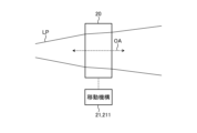
- the position adjustment unit 21 is configured by a moving mechanism 211 that can move the aberration generating unit 20 in the direction of the optical axis OA of the pulsed light LP.
- the beam diameter of the pulsed light LP can be adjusted by operating the moving mechanism 211 to adjust the position of the aberration generating unit 20 in the direction of the optical axis OA of the pulsed light LP according to the repetition frequency.
- the beam diameter can be adjusted with a small amount of movement, which makes it possible to miniaturize the device.
- the rotation mechanism 212 rotates the aberration generating unit 20 around an axis in a direction different from the direction of the optical axis OA of the pulsed light LP, i.e., an axis that is not parallel to the optical axis OA of the pulsed light LP, so that the length of the pulsed light LP passing through the aberration generating unit 20 can be changed.
- the length of the pulsed light LP passing through the aberration generating unit 20 is the interaction length between the pulsed light LP and the aberration generating unit 20.
- the interaction length between the pulsed light LP and the aberration generating unit 20 corresponds to the medium length L of the pulsed light LP passing through the aberration generating unit 20.
- the rotation mechanism 212 can rotate the aberration generating unit 20 around an axis perpendicular to the paper surface of FIG. 6.
- the interaction length between the pulsed light LP and the aberration generating unit 20 can be adjusted, and the amount of aberration due to the optical Kerr effect can be adjusted.
- two aberration generating units 20 are arranged facing each other, and each is rotated by the same angle in the opposite directions, thereby achieving the effect of canceling out the optical axis shift caused by the rotation of the aberration generating unit 20.
- FIG. 6 two aberration generating units 20 are arranged facing each other, and each is rotated by the same angle in the opposite directions, thereby achieving the effect of canceling out the optical axis shift caused by the rotation of the aberration generating unit 20.
- the laser device 100 has two aberration generating units 20 and two rotation mechanisms 212, but may have one aberration generating unit 20 and one rotation mechanism 212.
- the placement adjustment unit 21 may have the movement mechanism 211 shown in FIG. 5 and the rotation mechanism 212 shown in FIG. 6.
- the amount of aberration can be adjusted by adjusting the position of the aberration generating unit 20 in the direction of the optical axis OA, or by adjusting the rotation angle of the aberration generating unit 20 about an axis that is not parallel to the optical axis OA of the pulsed light LP.
- the beam shaping optical system 30 utilizes the aberration of the pulsed light generated by the aberration generating unit 20 to adjust at least one of the beam diameter and intensity distribution of the pulsed light in the solid active medium 41. However, if the beam diameter and intensity distribution in the solid active medium 41 of the pulsed light in which the aberration has been generated by the aberration generating unit 20 when the repetition frequency of the pulsed light is changed does not change the beam quality of the pulsed light after passing through the solid active medium 41, the beam shaping optical system 30 does not need to adjust the beam diameter and intensity distribution of the pulsed light in the solid active medium 41.
- the intensity distribution of the pulsed light on the optical axis at the incident surface of the solid active medium 41 deviates from an ideal Gaussian distribution.
- the refractive index distribution and phase modulation due to the optical Kerr effect depend on the distribution of the peak intensity I(r), so even if the beam diameter is the same, if the distribution of the peak intensity I(r) is different, the beam quality after passing through the solid active medium 41 may change.
- the beam diameter in this disclosure refers to the second moment diameter.
- the change in the beam quality of the pulsed light after passing through the solid active medium 41 will be large.
- the intensity distribution near the center of the optical axis of the pulsed light is broader than an ideal Gaussian distribution having the same beam diameter as the pulsed light, the change in the beam quality of the pulsed light after passing through the solid active medium 41 will be small.
- the intensity distribution near the center of the optical axis of the pulsed light can be approximated by a quadratic curve
- the refractive index distribution due to the optical Kerr effect can be regarded as an ideal lens with no aberration, and the beam quality after transmission does not change.
- the intensity distribution of the pulsed light is top-hat or high-order super-Gaussian, no refractive index distribution is formed due to the optical Kerr effect, and the beam quality after transmission does not change.
- the beam shaping optical system 30 is operated so that at least one of the principal point position and focal length is changed when the beam shaping optical system 30 is considered as a composite lens, in order to adjust at least one of the beam diameter and intensity distribution of the pulsed light. That is, the arrangement of the components that are optical elements constituting the beam shaping optical system 30 is operated by the arrangement adjustment unit 31.
- This operation is an operation that changes at least one of the principal point position and focal length when the beam shaping optical system 30 is considered as a composite lens.
- this operation can also be considered as an operation that changes at least one of the elements of the ABCD matrix of the composite lens.
- FIG. 7 is a schematic diagram showing an example of the configuration of the beam shaping optical system of the laser device according to the first embodiment.
- the beam shaping optical system 30 has two plano-convex lenses 301 and one plano-concave lens 302.
- the two plano-convex lenses 301 and one plano-concave lens 302 are an example of optical elements constituting the beam shaping optical system 30.
- a moving mechanism 311 is provided for each of the two plano-convex lenses 301 and one plano-concave lens 302.
- the moving mechanism 311 has a function of moving the components of the beam shaping optical system 30 in the optical axis direction of the pulsed light, or a function of moving the components of the beam shaping optical system 30 in a direction to remove them from the optical axis of the pulsed light.
- the moving mechanism 311 has a function of adjusting the position of each lens 301, 302 with respect to the optical axis direction of the pulsed light and removing each lens 301, 302 from the optical path.
- the moving mechanism 311 is an example of the arrangement adjustment unit 31. Note that the number and types of lenses 301 and 302 are not limited to those shown in FIG. 7.
- FIG. 8 shows an example of the results of simulating the intensity distribution at the incident surface of the solid active medium by applying a beam shaping optical system to the pulsed light transmitted through the aberration generating section.
- the horizontal axis indicates the position of the pulsed light incident on the incident surface of the solid active medium 41
- the vertical axis indicates the intensity of the pulsed light.
- the dotted line graph in FIG. 8 shows the results of simulating the intensity distribution at the incident surface of the solid active medium 41 by applying the beam shaping optical system 30 to the pulsed light transmitted through the aberration generating section 20.
- the four dotted line graphs correspond to four different operations of the beam shaping optical system 30. These four dotted line graphs have different intensity distributions, but all have the same beam diameter.
- FIG. 8 an ideal Gaussian distribution having the same beam diameter as each dotted line is shown in FIG. 8 as a solid line graph. From the results in FIG. 8, it can be seen that at least one of the beam diameter and intensity distribution of the pulsed light in the solid active medium 41 can be adjusted by manipulating the beam shaping optical system 30, i.e., by configuring the positions of the lenses 301 and 302 that make up the beam shaping optical system 30 or by removing the lenses 301 and 302 from the optical path.
- the position of the aberration generating unit 20 is changed by the placement adjustment unit 21, or at least one of the principal point position and the focal length when the beam shaping optical system 30 is considered as a single composite lens is changed by the placement adjustment unit 31, depending on the repetition frequency of the pulsed light.
- the placement adjustment unit in the broad sense changes the position of the aberration generating unit, or at least one of the principal point position and the focal length when the beam shaping optical system is considered as a single composite lens, depending on the repetition frequency of the pulsed light.
- the laser device 100 of the first embodiment includes a seed light source 10 that outputs pulsed light and can control the repetition frequency of the pulsed light, an aberration generating unit 20 that adds aberration due to the optical Kerr effect to the pulsed light, a beam shaping optical system 30 that adjusts at least one of the beam diameter and intensity distribution of the pulsed light, and at least one of the arrangement adjusting units 21 and 31 that are arrangement adjusting units that can operate at least one of the aberration generating unit 20 and the beam shaping optical system 30 according to the repetition frequency of the pulsed light.
- the ratio of the axial intensity of the pulsed light to the axial intensity of an ideal Gaussian beam with the same output and beam diameter as the pulsed light is changed according to the repetition frequency of the pulsed light.
- the control unit 11 may control at least one of the placement adjustment unit 21, which adjusts the placement of the aberration generation unit 20, and the placement adjustment unit 31, which adjusts the placement of the beam shaping optical system 30, so that changes in the beam quality of the pulsed light incident on the solid active medium 41 are suppressed when the repetition frequency of the pulsed light is changed.
- FIG. 9 is a diagram showing a schematic example of the configuration of a laser processing apparatus including a laser device according to a second embodiment.
- an optical Kerr medium is used for the aberration generating unit 20.
- the aberration generating unit 20a is different from that in the first embodiment. That is, in the laser device 100a in the laser processing apparatus 1a according to the second embodiment, a solid active medium is used for the aberration generating unit 20a. However, the solid active medium used for the aberration generating unit 20a also functions as an optical Kerr medium.
- a solid active medium having a nonlinear refractive index n 2 of 1 ⁇ 10 ⁇ 19 m 2 /W or more, such as Nd:YVO 4 is used.
- the aberration generating unit 20a which is an optical Kerr medium, can function as a solid amplifier.
- the laser device 100a further includes an excitation light source 22 and a dichroic mirror 23 in addition to the configuration of embodiment 1.
- the excitation light source 22 is a light source that outputs laser light that excites the aberration generating unit 20a.
- a semiconductor laser is preferably used for the excitation light source 22.
- the excitation light source 22 is often a fiber-coupled semiconductor laser.
- the wavelength of the laser light output from the excitation light source 22 is selected according to the absorption spectrum of the aberration generating unit 20a. In one example, when the solid active medium 41 is Nd: YVO4 , laser light with wavelengths of 808 nm, 879 nm, 888 nm, and 914 nm is used.
- excitation by laser light with wavelengths of 879 nm, 888 nm, and 914 nm which is direct excitation, has the advantage of generating less heat due to quantum defects and reducing the temperature rise of the solid active medium 41 associated with excitation.
- the dichroic mirror 23 is provided to make the pulsed light from the seed light source 10 and the excitation light from the excitation light source 22 incident on the same axis on the aberration generating unit 20a.
- the excitation light output from the excitation light source 22 is transmitted through or reflected by the dichroic mirror 23 and incident on the solid active medium 41 on the same axis as the pulsed light.
- the dichroic mirror 23 is configured to transmit the pulsed light from the seed light source 10 and reflect the excitation light from the excitation light source 22.
- the technology of embodiment 2 can be applied to a laser device composed of a two-stage solid-state amplifier.
- the optical Kerr effect that occurs in the aberration generating unit 20a which is the first-stage solid-state active medium, is utilized to suppress changes in the beam propagation characteristics of the pulsed amplified light after it is emitted from the second-stage solid-state active medium 41.
- the same solid-state active medium for the aberration generating unit 20a and the solid-state active medium 41 it is possible to reduce the number of component types and lower costs.
- the aberration generation unit 20a is configured from a solid-state active medium with a nonlinear refractive index n2 of 1 ⁇ 10 ⁇ 19 m 2 /W or more. This has the effect of allowing the aberration generation unit 20a to function as a solid-state amplifier. In addition, by using the same solid-state active medium for the aberration generation unit 20a and the solid-state active medium 41, it has the effect of reducing the number of component types and lowering costs.
- 1, 1a laser processing device 10 seed light source, 11 control unit, 20, 20a aberration generation unit, 21, 31 arrangement adjustment unit, 22, 42 excitation light source, 23, 43 dichroic mirror, 30 beam shaping optical system, 40 solid amplifier, 41 solid active medium, 50 wavelength conversion crystal, 60 processing optical system, 70 processing object, 100, 100a laser device, 201 entrance surface, 202 exit surface, 211, 311 movement mechanism, 212 rotation mechanism, 301 plano-convex lens, 302 plano-concave lens, LP pulsed light, OA optical axis, ⁇ Bi, ⁇ Bo Brewster angle.
Landscapes
- Physics & Mathematics (AREA)
- Electromagnetism (AREA)
- Optics & Photonics (AREA)
- Engineering & Computer Science (AREA)
- Plasma & Fusion (AREA)
- Condensed Matter Physics & Semiconductors (AREA)
- General Physics & Mathematics (AREA)
- Lasers (AREA)
- Optical Modulation, Optical Deflection, Nonlinear Optics, Optical Demodulation, Optical Logic Elements (AREA)
- Laser Beam Processing (AREA)
Priority Applications (5)
| Application Number | Priority Date | Filing Date | Title |
|---|---|---|---|
| PCT/JP2023/038269 WO2025088680A1 (ja) | 2023-10-24 | 2023-10-24 | レーザ装置およびレーザ加工装置 |
| JP2024502677A JP7459410B1 (ja) | 2023-10-24 | 2023-10-24 | レーザ装置およびレーザ加工装置 |
| KR1020257041181A KR20250178273A (ko) | 2023-10-24 | 2023-10-24 | 레이저 장치 및 레이저 가공 장치 |
| CN202380099963.9A CN121420434A (zh) | 2023-10-24 | 2023-10-24 | 激光装置及激光加工装置 |
| TW113132574A TWI897602B (zh) | 2023-10-24 | 2024-08-29 | 雷射裝置及雷射加工裝置 |
Applications Claiming Priority (1)
| Application Number | Priority Date | Filing Date | Title |
|---|---|---|---|
| PCT/JP2023/038269 WO2025088680A1 (ja) | 2023-10-24 | 2023-10-24 | レーザ装置およびレーザ加工装置 |
Publications (1)
| Publication Number | Publication Date |
|---|---|
| WO2025088680A1 true WO2025088680A1 (ja) | 2025-05-01 |
Family
ID=90474226
Family Applications (1)
| Application Number | Title | Priority Date | Filing Date |
|---|---|---|---|
| PCT/JP2023/038269 Pending WO2025088680A1 (ja) | 2023-10-24 | 2023-10-24 | レーザ装置およびレーザ加工装置 |
Country Status (5)
| Country | Link |
|---|---|
| JP (1) | JP7459410B1 (https=) |
| KR (1) | KR20250178273A (https=) |
| CN (1) | CN121420434A (https=) |
| TW (1) | TWI897602B (https=) |
| WO (1) | WO2025088680A1 (https=) |
Families Citing this family (1)
| Publication number | Priority date | Publication date | Assignee | Title |
|---|---|---|---|---|
| JP7672594B1 (ja) * | 2024-08-09 | 2025-05-07 | 三菱電機株式会社 | レーザ装置およびレーザ加工装置 |
Citations (4)
| Publication number | Priority date | Publication date | Assignee | Title |
|---|---|---|---|---|
| JP2010234444A (ja) * | 2009-03-11 | 2010-10-21 | Omron Corp | レーザ加工装置 |
| JP2013102088A (ja) * | 2011-11-09 | 2013-05-23 | Fujikura Ltd | Mopa方式レーザ光源装置およびmopa方式レーザ制御方法 |
| WO2021181511A1 (ja) * | 2020-03-10 | 2021-09-16 | 三菱電機株式会社 | 波長変換レーザ装置および波長変換レーザ加工機 |
| JP7254260B1 (ja) * | 2022-09-12 | 2023-04-07 | 三菱電機株式会社 | 固体レーザ装置および固体レーザ加工装置 |
Family Cites Families (5)
| Publication number | Priority date | Publication date | Assignee | Title |
|---|---|---|---|---|
| KR101680882B1 (ko) | 2014-04-22 | 2017-02-13 | 홀로스페이스 주식회사 | 초다시점 영상 배열 획득을 위한 카메라 배열방법 |
| JP7441780B2 (ja) * | 2020-12-21 | 2024-03-01 | 浜松ホトニクス株式会社 | 光パルス生成装置及び光パルス生成方法 |
| CN117677459A (zh) * | 2021-09-16 | 2024-03-08 | 株式会社片冈制作所 | 激光加工装置、探针卡的生产方法和激光加工方法 |
| CN116224678A (zh) * | 2023-03-14 | 2023-06-06 | 中国科学院半导体研究所 | 孤子光频梳及光生微波信号产生装置及其产生方法 |
| CN116526275B (zh) * | 2023-05-17 | 2025-08-19 | 北京大学 | 基于凹球面体镜片与多通腔的超短脉冲产生装置及方法 |
-
2023
- 2023-10-24 WO PCT/JP2023/038269 patent/WO2025088680A1/ja active Pending
- 2023-10-24 KR KR1020257041181A patent/KR20250178273A/ko active Pending
- 2023-10-24 JP JP2024502677A patent/JP7459410B1/ja active Active
- 2023-10-24 CN CN202380099963.9A patent/CN121420434A/zh active Pending
-
2024
- 2024-08-29 TW TW113132574A patent/TWI897602B/zh active
Patent Citations (4)
| Publication number | Priority date | Publication date | Assignee | Title |
|---|---|---|---|---|
| JP2010234444A (ja) * | 2009-03-11 | 2010-10-21 | Omron Corp | レーザ加工装置 |
| JP2013102088A (ja) * | 2011-11-09 | 2013-05-23 | Fujikura Ltd | Mopa方式レーザ光源装置およびmopa方式レーザ制御方法 |
| WO2021181511A1 (ja) * | 2020-03-10 | 2021-09-16 | 三菱電機株式会社 | 波長変換レーザ装置および波長変換レーザ加工機 |
| JP7254260B1 (ja) * | 2022-09-12 | 2023-04-07 | 三菱電機株式会社 | 固体レーザ装置および固体レーザ加工装置 |
Also Published As
| Publication number | Publication date |
|---|---|
| JP7459410B1 (ja) | 2024-04-01 |
| CN121420434A (zh) | 2026-01-27 |
| TW202517385A (zh) | 2025-05-01 |
| JPWO2025088680A1 (https=) | 2025-05-01 |
| TWI897602B (zh) | 2025-09-11 |
| KR20250178273A (ko) | 2025-12-26 |
Similar Documents
| Publication | Publication Date | Title |
|---|---|---|
| JP5649548B2 (ja) | サブ213nm波長を生成するためのCLBOにおける非臨界位相整合 | |
| US8248688B2 (en) | Tandem photonic amplifier | |
| CN105210245B (zh) | 具有圆形输出光束的高效单通型谐波发生器 | |
| KR102898536B1 (ko) | 심자외선 레이저 소스 | |
| JP2011128330A (ja) | レーザ装置 | |
| TWI897602B (zh) | 雷射裝置及雷射加工裝置 | |
| JP2008511177A (ja) | 半導体検査用のファイバ増幅器ベースの光源 | |
| JP6588707B2 (ja) | レーザ光源装置及びレーザパルス光生成方法 | |
| KR102083267B1 (ko) | 고출력 극초단 펄스 레이저 장치 | |
| Yoon et al. | Ultra-high intensity lasers as tools for novel physics | |
| CN204558874U (zh) | 用于产生不同波长的两个激光射束的激光振荡器 | |
| JP6687999B2 (ja) | レーザ光源装置及びレーザパルス光生成方法 | |
| CN105490144A (zh) | 一种基于自相似放大器的可调谐紫外光的产生方法 | |
| JP7254260B1 (ja) | 固体レーザ装置および固体レーザ加工装置 | |
| JP2013201328A (ja) | ファイバ増幅装置とそのスペクトル幅を調整する方法及び該ファイバ増幅装置を備えるレーザ加工システムとその光損失を低減する方法 | |
| JP6571943B2 (ja) | レーザ光源装置及びレーザパルス光生成方法 | |
| JP4449614B2 (ja) | 波長変換光学系及びレーザ装置 | |
| Xu et al. | Extremely efficient, high beam quality second harmonic generation using a thin-disk regenerative amplifier | |
| CN105490145A (zh) | 一种基于自相似放大器的可调谐紫外光的产生装置 | |
| JP2006343786A (ja) | 波長変換装置 | |
| Rustad et al. | High-pulse energy mid-infrared laser source | |
| CN119422296A (zh) | 利用端泵浦的固态激光谐振器中的腔内频率转换 | |
| JP2026511265A (ja) | レーザ活性媒体を光ポンピングするための光源 | |
| Xuan et al. | High power Yb: YAG ceramics laser and diamond Raman laser for frequency conversion to DUV | |
| Yoshida et al. | High-power phase-conjugating mirror based on stimulated Brillouin scattering in liquid and solid materials |
Legal Events
| Date | Code | Title | Description |
|---|---|---|---|
| ENP | Entry into the national phase |
Ref document number: 2024502677 Country of ref document: JP Kind code of ref document: A |
|
| WWE | Wipo information: entry into national phase |
Ref document number: 2024502677 Country of ref document: JP |
|
| 121 | Ep: the epo has been informed by wipo that ep was designated in this application |
Ref document number: 23956738 Country of ref document: EP Kind code of ref document: A1 |
|
| ENP | Entry into the national phase |
Ref document number: 1020257041181 Country of ref document: KR Free format text: ST27 STATUS EVENT CODE: A-0-1-A10-A15-NAP-PA0105 (AS PROVIDED BY THE NATIONAL OFFICE) |
|
| WWE | Wipo information: entry into national phase |
Ref document number: 1020257041181 Country of ref document: KR |
|
| WWP | Wipo information: published in national office |
Ref document number: 1020257041181 Country of ref document: KR |