WO2025079677A1 - 電池ケース及びリチウムイオン電池 - Google Patents
電池ケース及びリチウムイオン電池 Download PDFInfo
- Publication number
- WO2025079677A1 WO2025079677A1 PCT/JP2024/036410 JP2024036410W WO2025079677A1 WO 2025079677 A1 WO2025079677 A1 WO 2025079677A1 JP 2024036410 W JP2024036410 W JP 2024036410W WO 2025079677 A1 WO2025079677 A1 WO 2025079677A1
- Authority
- WO
- WIPO (PCT)
- Prior art keywords
- battery case
- steel sheet
- battery
- lid
- case
- Prior art date
- Legal status (The legal status is an assumption and is not a legal conclusion. Google has not performed a legal analysis and makes no representation as to the accuracy of the status listed.)
- Pending
Links
Images




Classifications
-
- H—ELECTRICITY
- H01—ELECTRIC ELEMENTS
- H01M—PROCESSES OR MEANS, e.g. BATTERIES, FOR THE DIRECT CONVERSION OF CHEMICAL ENERGY INTO ELECTRICAL ENERGY
- H01M10/00—Secondary cells; Manufacture thereof
- H01M10/05—Accumulators with non-aqueous electrolyte
- H01M10/052—Li-accumulators
-
- H—ELECTRICITY
- H01—ELECTRIC ELEMENTS
- H01M—PROCESSES OR MEANS, e.g. BATTERIES, FOR THE DIRECT CONVERSION OF CHEMICAL ENERGY INTO ELECTRICAL ENERGY
- H01M10/00—Secondary cells; Manufacture thereof
- H01M10/05—Accumulators with non-aqueous electrolyte
- H01M10/056—Accumulators with non-aqueous electrolyte characterised by the materials used as electrolytes, e.g. mixed inorganic/organic electrolytes
- H01M10/0564—Accumulators with non-aqueous electrolyte characterised by the materials used as electrolytes, e.g. mixed inorganic/organic electrolytes the electrolyte being constituted of organic materials only
- H01M10/0566—Liquid materials
-
- H—ELECTRICITY
- H01—ELECTRIC ELEMENTS
- H01M—PROCESSES OR MEANS, e.g. BATTERIES, FOR THE DIRECT CONVERSION OF CHEMICAL ENERGY INTO ELECTRICAL ENERGY
- H01M50/00—Constructional details or processes of manufacture of the non-active parts of electrochemical cells other than fuel cells, e.g. hybrid cells
- H01M50/10—Primary casings; Jackets or wrappings
- H01M50/102—Primary casings; Jackets or wrappings characterised by their shape or physical structure
- H01M50/103—Primary casings; Jackets or wrappings characterised by their shape or physical structure prismatic or rectangular
-
- H—ELECTRICITY
- H01—ELECTRIC ELEMENTS
- H01M—PROCESSES OR MEANS, e.g. BATTERIES, FOR THE DIRECT CONVERSION OF CHEMICAL ENERGY INTO ELECTRICAL ENERGY
- H01M50/00—Constructional details or processes of manufacture of the non-active parts of electrochemical cells other than fuel cells, e.g. hybrid cells
- H01M50/10—Primary casings; Jackets or wrappings
- H01M50/102—Primary casings; Jackets or wrappings characterised by their shape or physical structure
- H01M50/107—Primary casings; Jackets or wrappings characterised by their shape or physical structure having curved cross-section, e.g. round or elliptic
-
- H—ELECTRICITY
- H01—ELECTRIC ELEMENTS
- H01M—PROCESSES OR MEANS, e.g. BATTERIES, FOR THE DIRECT CONVERSION OF CHEMICAL ENERGY INTO ELECTRICAL ENERGY
- H01M50/00—Constructional details or processes of manufacture of the non-active parts of electrochemical cells other than fuel cells, e.g. hybrid cells
- H01M50/10—Primary casings; Jackets or wrappings
- H01M50/116—Primary casings; Jackets or wrappings characterised by the material
- H01M50/117—Inorganic material
- H01M50/119—Metals
-
- H—ELECTRICITY
- H01—ELECTRIC ELEMENTS
- H01M—PROCESSES OR MEANS, e.g. BATTERIES, FOR THE DIRECT CONVERSION OF CHEMICAL ENERGY INTO ELECTRICAL ENERGY
- H01M50/00—Constructional details or processes of manufacture of the non-active parts of electrochemical cells other than fuel cells, e.g. hybrid cells
- H01M50/10—Primary casings; Jackets or wrappings
- H01M50/116—Primary casings; Jackets or wrappings characterised by the material
- H01M50/124—Primary casings; Jackets or wrappings characterised by the material having a layered structure
-
- H—ELECTRICITY
- H01—ELECTRIC ELEMENTS
- H01M—PROCESSES OR MEANS, e.g. BATTERIES, FOR THE DIRECT CONVERSION OF CHEMICAL ENERGY INTO ELECTRICAL ENERGY
- H01M50/00—Constructional details or processes of manufacture of the non-active parts of electrochemical cells other than fuel cells, e.g. hybrid cells
- H01M50/10—Primary casings; Jackets or wrappings
- H01M50/131—Primary casings; Jackets or wrappings characterised by physical properties, e.g. gas permeability, size or heat resistance
- H01M50/133—Thickness
-
- H—ELECTRICITY
- H01—ELECTRIC ELEMENTS
- H01M—PROCESSES OR MEANS, e.g. BATTERIES, FOR THE DIRECT CONVERSION OF CHEMICAL ENERGY INTO ELECTRICAL ENERGY
- H01M50/00—Constructional details or processes of manufacture of the non-active parts of electrochemical cells other than fuel cells, e.g. hybrid cells
- H01M50/10—Primary casings; Jackets or wrappings
- H01M50/14—Primary casings; Jackets or wrappings for protecting against damage caused by external factors
- H01M50/145—Primary casings; Jackets or wrappings for protecting against damage caused by external factors for protecting against corrosion
-
- H—ELECTRICITY
- H01—ELECTRIC ELEMENTS
- H01M—PROCESSES OR MEANS, e.g. BATTERIES, FOR THE DIRECT CONVERSION OF CHEMICAL ENERGY INTO ELECTRICAL ENERGY
- H01M50/00—Constructional details or processes of manufacture of the non-active parts of electrochemical cells other than fuel cells, e.g. hybrid cells
- H01M50/10—Primary casings; Jackets or wrappings
- H01M50/147—Lids or covers
- H01M50/148—Lids or covers characterised by their shape
- H01M50/15—Lids or covers characterised by their shape for prismatic or rectangular cells
-
- H—ELECTRICITY
- H01—ELECTRIC ELEMENTS
- H01M—PROCESSES OR MEANS, e.g. BATTERIES, FOR THE DIRECT CONVERSION OF CHEMICAL ENERGY INTO ELECTRICAL ENERGY
- H01M50/00—Constructional details or processes of manufacture of the non-active parts of electrochemical cells other than fuel cells, e.g. hybrid cells
- H01M50/10—Primary casings; Jackets or wrappings
- H01M50/147—Lids or covers
- H01M50/148—Lids or covers characterised by their shape
- H01M50/152—Lids or covers characterised by their shape for cells having curved cross-section, e.g. round or elliptic
-
- H—ELECTRICITY
- H01—ELECTRIC ELEMENTS
- H01M—PROCESSES OR MEANS, e.g. BATTERIES, FOR THE DIRECT CONVERSION OF CHEMICAL ENERGY INTO ELECTRICAL ENERGY
- H01M50/00—Constructional details or processes of manufacture of the non-active parts of electrochemical cells other than fuel cells, e.g. hybrid cells
- H01M50/10—Primary casings; Jackets or wrappings
- H01M50/147—Lids or covers
- H01M50/166—Lids or covers characterised by the methods of assembling casings with lids
- H01M50/169—Lids or covers characterised by the methods of assembling casings with lids by welding, brazing or soldering
-
- Y—GENERAL TAGGING OF NEW TECHNOLOGICAL DEVELOPMENTS; GENERAL TAGGING OF CROSS-SECTIONAL TECHNOLOGIES SPANNING OVER SEVERAL SECTIONS OF THE IPC; TECHNICAL SUBJECTS COVERED BY FORMER USPC CROSS-REFERENCE ART COLLECTIONS [XRACs] AND DIGESTS
- Y02—TECHNOLOGIES OR APPLICATIONS FOR MITIGATION OR ADAPTATION AGAINST CLIMATE CHANGE
- Y02E—REDUCTION OF GREENHOUSE GAS [GHG] EMISSIONS, RELATED TO ENERGY GENERATION, TRANSMISSION OR DISTRIBUTION
- Y02E60/00—Enabling technologies; Technologies with a potential or indirect contribution to GHG emissions mitigation
- Y02E60/10—Energy storage using batteries
Definitions
- the present invention relates to a battery case and a lithium-ion battery.
- an oxide film is formed on at least a portion of the surface of the welded portion. This oxide film covers the surface of the welded portion (particularly the welded metal), preventing direct contact between the electrolyte and the welded metal, and contributing to the electrolyte resistance of the welded portion.
- the inventors' investigation into battery cases for lithium-ion batteries they have discovered that if a thick oxide film is formed on the inner surface of the battery case (the surface that houses the battery unit and electrolyte), the oxide film may peel off due to expansion and contraction during charging and discharging.
- the peeled oxide film may affect battery performance by entering the gaps between the electrodes. Therefore, the inventors have discovered that there is a need for technology that can prevent the peeling of the oxide film on the inner surface of the battery case while achieving excellent electrolyte resistance.
- the plated steel sheet is a Ni-based plated steel sheet
- the welded portion is a portion where the case body and the lid are joined to each other by laser welding
- the Ni content of the weld metal is at least 0.5 mass% higher than the Ni content of the base steel sheet in the thinner plated steel sheet of the Ni-based plated steel sheets constituting the case body and the lid
- the hardness of the weld metal is at least 1.2 times the hardness of the base steel sheet in the thinner plated steel sheet.
- the present invention makes it possible to provide a battery case and a lithium-ion battery that have excellent electrolyte resistance and can prevent the oxide film on the inner surface of the battery case from peeling off.
- FIG. 2 is an explanatory diagram showing a schematic diagram of the material of a battery case for a lithium ion battery according to the embodiment.
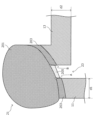
- 5 is a schematic diagram for explaining the structure of the inner surface side of the battery case in the vicinity of a welded portion of the battery case for the lithium ion battery according to the embodiment.
- FIG. 5 is a schematic diagram for explaining the structure of the inner surface side of the battery case in the vicinity of a welded portion of the battery case for the lithium ion battery according to the embodiment.
- FIG. 5 is a schematic diagram for explaining the structure of the inner surface side of the battery case in the vicinity of a welded portion of the battery case for the lithium ion battery according to the embodiment.
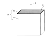
- FIGS 1A to 2B are explanatory diagrams that show a battery case for a lithium ion battery according to the present embodiment and a lithium ion battery using such a battery case. For convenience, the following description may be given using the coordinate axes shown in Figure 1A.
- battery unit 3 and electrolyte 5 there are no particular limitations on the positive electrode (not shown), negative electrode (not shown), separator (not shown), and various active materials (not shown) provided in the positive and negative electrodes that constitute the battery unit 3.
- various materials used in lithium ion batteries can be used as appropriate.
- the specific structure of the battery unit 3, and various structures can be adopted.
- the case body 11 of the battery case 10 is shown to have a rectangular shape.
- the specific shape of the case body 11 is not particularly regulated.
- the case body 11 can have any shape as long as it can accommodate the battery unit 3 and the electrolyte 5.
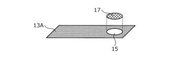
- a liquid injection port 15 which is an opening for injecting the electrolyte into the storage case, may be provided in part of the lid 13A, and after the electrolyte is injected, the liquid injection port 15 may be closed with a liquid injection port cover 17.
- a lid 13A as shown in FIG. 1B instead of the lid 13 shown in FIG. 1A.
- a battery case 10 as shown in FIG. 1A after the battery unit 3 and electrolyte 5 are housed in the internal space of the case body 11, the opening of the case body 11 is closed with the lid 13 and a sealing process is performed by welding. This causes the case body 11 and the lid 13 of the battery case 10 to be integrated. As a result, as shown diagrammatically in FIG. 2A, in the sealed battery case 10, a welded portion 21 is formed by welding the case body 11 and the lid 13 together.
- the case body 11 of the battery case 10 is illustrated as if it were made of a single member.
- the case body 11 may be made of a single member, or may be made of multiple members joined together by various types of welding (e.g., laser welding).
- two members are prepared by bending the metal material that will become the material of the battery case 10 into an approximately U-shape, and these approximately U-shaped members are butted together to form the shape of the side of the case body 11, and then the butted parts are welded together to form a joint.
- Fig. 3 is an explanatory diagram that shows a schematic diagram of the material of the battery case for a lithium ion battery according to this embodiment.
- FIG. 3 is a schematic diagram showing the layer structure of the plated steel sheet 100.
- the plated steel sheet 100 used as the material for the battery case 10 has a base steel sheet 101 as the base material for the plated steel sheet, and a plating layer 103 provided on the front and back surfaces of the base steel sheet 101.
- the base steel sheet 101 is a steel sheet that serves as the base material for the plated steel sheet 100.
- the components and metal structure of the base steel sheet 101 are not particularly limited.
- As the base steel sheet 101 various types of steel sheets can be appropriately used, such as low-carbon aluminum-killed steel, IF steel (Interstitial Free Steel), SULC steel (Super Ultra Low Carbon Steel), etc.
- the steel sheets used as the base steel sheet 101 for the case body 11 and the lids 13 and 13A may be different types.
- the plating layer 103 located on the surface of the base steel sheet 101 is preferably, for example, a Ni-based plating layer in which Ni is the main component of the plating composition, or an Al-based plating layer in which Al is the main component of the plating composition.
- a plating layer as the plating layer 103, the corrosion resistance of the battery case can be improved.
- the main constituent component of the plating layer means a component that is contained in an amount of 80.0 mass% or more in the plating composition of the plating layer 103 of the plated steel sheet 100 in the areas other than the welded portion 21 when focusing on the plated steel sheet 100 that constitutes the battery case 10. Furthermore, it is more preferable that the main constituent component of the plating layer is a component that is contained in an amount of 95.0 mass% or more in the plating composition of the plating layer 103 of the plated steel sheet 100 in the areas other than the welded portion 21 when focusing on the plated steel sheet 100 that constitutes the battery case 10.
- the average composition of the Ni-based plating layer or Al-based plating layer is not particularly limited. As long as it exhibits corrosion resistance to the electrolyte 5 held in the battery case 10, various types of Ni plating, Ni alloy plating, Al plating, Al alloy plating, etc. can be used as the plating layer 103.
- Methods for forming the plating layer 103 as described above include various plating methods such as hot-dip plating using a plating bath, electroplating, etc., as well as thermal spraying and vapor deposition.
- An oxide coating layer (not shown) is formed on at least a portion of the surface (the surface in contact with the atmosphere) of the welded portion 21 thus formed.
- an oxide layer is formed on the surface of the welded portion 21 as a result of welding. Such an oxide layer is also formed on the surface of the welded portion 21 on the inner side of the battery case. By covering the surface of the welded portion (particularly the welded metal), this oxide layer prevents direct contact between the electrolyte 5 and the welded metal, and contributes to the electrolyte resistance of the welded portion 21.
- the thickness of the oxide coating layer is 5.0 ⁇ m or less, so it is possible to prevent the above-mentioned peeling of the oxide coating layer.
- the welded portion 21 As shown in Fig. 5A and Fig. 5B, the welded portion 21 according to the present embodiment has a weld metal 201.
- a heat-affected zone (HAZ) 203 exists in the portion of the case body 11 on the side of the welded metal 201 and in the portion of the cover 13 on the side of the welded metal 201 due to heat generated during welding between the case body 11 and the cover 13.
- Such welded metal 201 and heat-affected zone 203 can be easily distinguished from the difference in how they are visually recognized when a cross section of the battery case 10 including the welded portion 21 as shown in Fig. 5A and Fig.
- FIG. 5B is observed with a scanning electron microscope (SEM) (e.g., JSM-7000F manufactured by JEOL Corporation). Note that although Figures 5A and 5B illustrate the case where a heat-affected zone 203 is present, when a cross section of the battery case 10 including the welded portion 21 is observed by SEM, the heat-affected zone 203 may not be present.
- SEM scanning electron microscope
- the weld metal 201 is the metal that melts during welding and then solidifies again from the plated steel sheet 100, which is the material of the case body 11 and the lid 13. Therefore, the weld metal 201 is composed of various alloys of components derived from the base steel sheet 101 in the plated steel sheet 100 and components derived from the plating layer 103 in the plated steel sheet 100. Furthermore, the weld metal 201 may contain impurities in addition to the above components.
- the weld metal 201 located on the inner surface side of the battery case 10 contains 0.3% by mass or more and less than 60.0% by mass of the main constituent components of the plating layer 103 of the plated steel sheet 100, which is the material of the case body 11 and the lid 13.
- the weld metal 201 located on the inner surface side of the battery case 10 contains 0.3% by mass or more and less than 60.0% by mass of Ni.
- the weld metal 201 located on the inner surface side of the battery case 10 contains 0.3% by mass or more and less than 60.0% by mass of Al.
- the size of the gap 23 between the case body 11 and the lid 13, as described in detail below, needs to be 50 ⁇ m or less.
- the content of the main component of the plating layer 103 in the weld metal 201 located on the inner surface side of the battery case 10 is made less than 60.0 mass %.
- the content of the main component of the plating layer 103 in the weld metal 201 located on the inner surface side of the battery case 10 is preferably 50.0 mass% or less, more preferably 20.0 mass% or less, even more preferably less than 20.0 mass%, and even more preferably 10.0 mass% or less.
- the content of the main constituents of the plating layer 103 in the weld metal 201 located on the inner surface side of the battery case 10 as described above can be confirmed, for example, as follows.
- a sample for cross-sectional observation including the welded portion 21 of the battery case 10 is cut out from the center of the depth direction of the battery case 10 (Y-axis direction in FIG. 1A).
- the cutting direction for obtaining the cross section is the plate thickness direction of the lid portion 13 (the case longitudinal direction of the battery case 10 (Z-axis direction in FIG. 1A)).
- the obtained sample for cross-sectional observation is embedded in resin, and then appropriately polished, and the obtained cross section is observed and measured by a scanning electron microscope (SEM).
- the oxide film layer 205 is composed of an oxide of Ni derived from the plated layer 103, an oxide of Fe (e.g., FeO) derived from the base steel sheet 101, etc.
- the oxide film layer 205 is composed of an oxide of Al derived from the plated layer 103, an oxide of Fe (e.g., FeO) derived from the base steel sheet 101, etc.
- the oxide film layer 205 may contain impurities in addition to the oxides mentioned above.
- the thickness of the oxide coating layer 205 as shown in FIGS. 5A and 5B is 5.0 ⁇ m or less. If the thickness of the oxide coating layer 205 located on the inner surface of the battery case 10 at the welded portion 21 exceeds 5.0 ⁇ m, the oxide coating layer 205 formed on the inner surface of the battery case 10 becomes too thick, and as a result, the oxide coating layer 205 peels off due to expansion and contraction during charging and discharging. By making the thickness of the oxide coating layer 205 5.0 ⁇ m or less, peeling of the oxide coating layer 205 can be prevented. In addition, the thickness of the oxide coating layer 205 located on the inner surface of the battery case 10 at the welded portion 21 is preferably 3.0 ⁇ m or less, and more preferably 2.0 ⁇ m or less.
- the manufacturing method described in detail below it is difficult to make the thickness of the oxide coating layer 205 zero, and the lower limit of the thickness of the oxide coating layer 205 is essentially about 5.0 nm.
- the thickness of the oxide layer 205 as described above can be measured using SEM-EPMA, in the same way as the content of the main components of the plating layer in the weld metal 201 described above.
- a depth profile showing the change in the oxygen (O) content is created with the contact point with the embedding resin on the inner surface of the battery case as the origin, and the region up to the point where the oxygen content peaks is taken as the portion of the oxide layer 205 described in detail below.
- the thickness of the oxide layer 205 determined as described above is measured at any 10 points in the observation region using the length measuring function implemented in the SEM-EPMA, and the average value is calculated using the 8 measurement values of the 10 measurement points obtained, excluding the maximum and minimum values. The average value obtained in this way is treated as the thickness of the oxide layer 205.
- the size of the gap 23 is preferably 30% or less of the sum of the plate thickness of the case body 11 at the portion of the battery case 10 other than the welded portion 21 (i.e., the total thickness of the base steel sheet 101 and the plating layer 103) and the plate thickness of the lid 13 at the portion of the battery case 10 other than the welded portion 21 (i.e., the total thickness of the base steel sheet 101 and the plating layer 103).
- the size of the gap 23 is 30.0% or less of the total thickness of the case body 11 at the portion other than the welded portion 21 (thickness d1 in FIG. 5A and FIG. 5B) and the thickness of the lid portion 13 at the portion other than the welded portion 21 (thickness d2 in FIG. 5A and FIG. 5B). Even if a part of the oxide coating layer 205 having a thickness of 5.0 ⁇ m or less in this embodiment peels off due to some factor, the size of the peeled oxide coating layer 205 becomes very small. This makes it possible to further reduce the possibility that the peeled oxide coating layer 205 will reach the battery unit 3. As a result, it is possible to further reduce the possibility of affecting the battery performance.
- the size of the above-mentioned gap 23 can be determined as follows. Note that for the sake of convenience, Figures 5A and 5B show the case body 11 and lid 13 (particularly lid 13) as if they have no curved portions. However, depending on the shapes of the case body 11 and lid 13, it is possible that curved portions exist in the portions that form the gap 23. However, by making observations using the method described below, it is possible to unambiguously determine the size of the above-mentioned gap 23.
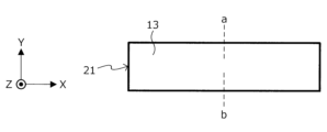
- FIG. 6 is a schematic diagram for explaining the position of the cutting line when performing cross-sectional observation to identify the size of the void in the lithium ion battery according to this embodiment.
- FIG. 6 shows a schematic diagram of the lid portion 13 and the welded portion 21 when the lithium ion battery 1 according to this embodiment is viewed in plan from above the lid portion 13.
- the sample for cross-sectional observation obtained as described above is embedded in resin, then appropriately polished, and the cross-section obtained is observed with a scanning electron microscope (SEM) (for example, JSM-7000F manufactured by JEOL Corporation).
- SEM scanning electron microscope
- the size of the field of view during observation may be 1000 ⁇ m ⁇ 1000 ⁇ m.
- a cross-section such as that shown in FIG. 5A or FIG. 5B is obtained.
- the surface of the inner side of the battery case 10 in the case body 11 is traced toward the weld metal 201, and the intersection of the interface between the weld metal 201 and the heat-affected zone 203 (or, if the heat-affected zone 203 does not exist, the interface between the weld metal 201 and the plated steel sheet 100, which is the base metal) is taken as point A.
- the surface of the inner side of the battery case 10 in the lid 13 is traced toward the weld metal 201, and the intersection of the interface between the weld metal 201 and the heat-affected zone 203 (or, if the heat-affected zone 203 does not exist, the interface between the weld metal 201 and the plated steel sheet 100, which is the base metal) is taken as point B.
- the distance between points A and B thus determined is measured.
- the distance between points A and B is measured for each of the two cross-sectional observation samples prepared as described above, and the average of the two measured values obtained is defined as the size of the gap 23.
- the distance between points A and B can be measured using the length measurement function implemented in the SEM.
- Ni-based plated steel sheet is used as the material for the case body 11 and the lid portions 13, 13A, and the case body 11 and the lid portions 13, 13A may be joined to each other by laser welding to form the welded portion 21.
- the steel sheet used as the material for the battery case 10 for the lithium-ion battery 1 is preferably one with a low content of alloying elements such as carbon (C) and manganese (Mn) in order to ensure high formability.
- alloying elements such as carbon (C) and manganese (Mn)
- the welded portion 21 formed by welding does not harden sufficiently, and the welded portion 21, which is discontinuous in shape, tends to be the weakest portion in terms of strength. Therefore, it is preferable that the hardness of the welded metal 201 is 1.2 times or more the hardness of the portion other than the welded portion 21 in the thinner plated steel sheet 100. This makes it possible to make the mechanical strength of the welded portion 21 in the battery case 10 in a more preferable state.
- the hardness of the welded metal 201 is more preferably more than 2.0 times the hardness of the portion other than the welded portion 21 in the thinner plated steel sheet 100.
- the welded metal 201 becomes 1.2 times more likely to harden than the base steel sheet 101 in the plated steel sheet 100, and a welded portion 21 with high strength and reliability that is resistant to repeated loads applied during charging and discharging of the battery can be obtained.
- the Ni content of the weld metal 201 is at least 0.7 mass% higher than the Ni content of the base steel sheet 101 in the thinner Ni-based plated steel sheet 100 that constitutes the case body 11 and the lids 13 and 13A.
- the above hardness can be measured at a specific location using a commercially available Vickers hardness tester according to the method described below.
- the case body 11 may be formed so that there are no joints, for example, by using a processing method such as drawing.
- the case body 11 may be formed by preparing multiple parts for forming the case body 11 (for example, multiple parts for forming the side surfaces of the case body 11 and parts for forming the bottom surface of the case body 11) using a processing method such as bending, and butting these parts together and laser welding them.
- the replacement time with the inert gas is set to 0.5 seconds or more.
- the size of the internal space of the battery case 10 also depends on the size of the battery case 10, but if the battery case 10 is of a general size, the internal space of the battery case 10 can be replaced with the inert gas by ensuring a replacement time of 1.0 second or more. Note that there is no particular restriction on the upper limit of the replacement time, but considering the productivity of the battery case 10, the upper limit is about 3.0 seconds.
- the inert gas is blown into the internal space of the battery case 10 while ensuring the above-mentioned replacement time. Then, during the welding operation, it is preferable to perform the welding operation while blowing in the inert gas from an opening that exists in a portion that does not affect the welding operation, such as the inlet port provided on the side of the case main body 11 or the inlet port 15 provided on the lid 13A. At this time, the blowing amount of the inert gas is 0.5 L/min or more, and the spraying amount of the inert gas is 20.0 L/min or more.
- the internal space of the battery case 10 is filled with inert gas even during welding, and a situation can be realized in which the surface of the weld metal 201 generated by welding is not easily oxidized.
- the upper limit of the blowing amount is not particularly specified, but is practically 1.0 L/min.
- the upper limit of the spraying amount from above is not particularly specified, but is practically about 50.0 L/min.
- the method for filling the internal space of the battery case 10 with an inert gas is not limited to blowing in an inert gas as described above.
- the above describes the battery case for a lithium-ion battery according to this embodiment and the method for manufacturing a lithium-ion battery using such a battery case.
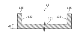
- FIG. 7A is an explanatory diagram that shows a schematic structure of a lid portion of the battery case for a lithium ion battery according to the present embodiment
- Figure 7B is an explanatory diagram that shows a schematic view of the vicinity of a welded portion of the battery case for a lithium ion battery according to the present embodiment.
- the lid portion 13 is a member having a generally U-shaped cross section, which includes a lid body portion 131 that closes the opening of the case body portion 11, and wall portions 133 that protrude from the lid body portion 131 at both ends of the lid body portion 131.
- the tip portion 135 of the wall portion 133 of the lid portion 13 is joined to the case body portion 11 to form the welded portion 21.
- the height h of the wall portion 133 is more preferably 1.1 times or more, and even more preferably 1.2 times or more, the thickness d2 of the lid body portion 131.
- the upper limit of the height h of the wall portion 133 is not particularly specified, but is essentially about 1.5 times the thickness d2 of the lid body portion 131.
- Test Example In the test example described below, a case main body 11 and a lid 13 having the shape shown in FIG. 1A were prepared, and a battery unit described below was prepared. These components were assembled to form a lithium ion battery.
- ⁇ Battery Case Body and Lid> ⁇ Base steel sheet The following steel sheets were prepared as the base material for the plated steel sheet that is the material for the battery case. For comparison, commercially available Al sheets were also prepared. Nb-SULC steel (manufactured by Nippon Steel Corporation) with a thickness of 0.2 to 1.4 mm was prepared as the material for the case body, and aluminum-killed steel (manufactured by Nippon Steel Corporation) with a thickness of 0.2 to 1.4 mm and Nb-SULC steel (manufactured by Nippon Steel Corporation) with a thickness of 0.2 to 1.4 mm were prepared as the material for the lid.
- Nb-SULC steel manufactured by Nippon Steel Corporation
- aluminum-killed steel manufactured by Nippon Steel Corporation
- Nb-SULC steel manufactured by Nippon Steel Corporation
- ⁇ Negative electrode plate Amorphous carbon was used as the negative electrode active material.
- the amorphous carbon was dry-mixed with acetylene black, a conductive material, to form a mixture.
- NMP N-methyl-2-pyrrolidone
- the resulting paste was applied to Cu foil and dried, then rolled to a specified thickness, and cut to a specified size to form the negative electrode plate.
- Lithium-ion battery manufacturing procedure A separator was sandwiched between the positive and negative plates obtained as described above, and then wound to form an electrode unit.
- the battery unit was crushed into a shape that could be inserted into the internal space of the case body, and the positive plate was welded to an Al lead and the negative plate was welded to a Ni lead.
- the Al lead was welded to a positive terminal provided in the lid, and the Ni lead was welded to a negative terminal provided in the lid.
- the content of the main components of the plating layer in the weld metal, the content of the main components of the plating layer in areas other than the weld (i.e., the areas of the plated steel sheet as the base material), the thickness of the oxide film layer, and the size of voids were measured using an SEM (JSM-7000F, manufactured by JEOL Corp.) and an SEM-EPMA (JXA-8230, manufactured by JEOL Corp.) in accordance with the method previously described. The results obtained are shown in Table 2 below. Note that in Table 2 below, the term "main components of the plating layer" is abbreviated to "plating components.”
- cross-sectional observation samples obtained as described above were used to measure the Vickers hardness of the weld metal and areas other than the weld, according to the method previously described.
- Vickers hardness of weld metal/Vickers hardness of the thinner plated steel sheet other than the weld was evaluated according to the following criteria. ⁇ Evaluation criteria> Rating: "VG”: The ratio is more than 2.0 times; “G”: The ratio is 2.0 times or less and 1.2 times or more; “P”: The ratio is less than 1.2 times.
- the obtained lithium ion battery was evaluated from the viewpoints of inner surface electrolyte resistance and charge/discharge test.
- the lithium ion battery prepared as described above was kept at 80°C for 500 hours. After the holding, a part of the battery case was disassembled in an atmosphere of 25°C and a dew point of -76°C, and the electrolyte was collected with a pipette or the like.
- the Fe ion content in the obtained electrolyte was analyzed using a commercially available ICP mass spectrometer (Agilent 7700x ICP-MS manufactured by Agilent Technologies, Inc.). The obtained Fe ion content was evaluated according to the following criteria.
- VG Fe ion content is 50 ppm or less
- G Fe ion content is more than 50 ppm and less than 75 ppm
- P Fe ion content is more than 75 ppm.
- a battery case for a lithium ion battery having a case main body that houses a battery unit having a positive electrode, a negative electrode, and a separator, and an electrolyte solution containing a lithium salt, and a lid that seals the case main body
- the case body and the cover are made of a plated steel sheet having a plating layer formed on a base steel sheet
- the battery case has a welded portion at which the case body and the lid are joined to each other by welding
- the inner surface side of the battery case at the welded portion is A weld metal containing a main component of the plating layer in an amount of 0.3 mass% or more and less than 60.0 mass%; an oxide film layer present on a portion of the surface of the weld metal that may come into contact with the electrolyte; It has The thickness of the oxide coating layer is 5.0 ⁇ m or less.
Landscapes
- Chemical & Material Sciences (AREA)
- Chemical Kinetics & Catalysis (AREA)
- Electrochemistry (AREA)
- General Chemical & Material Sciences (AREA)
- Inorganic Chemistry (AREA)
- Engineering & Computer Science (AREA)
- Manufacturing & Machinery (AREA)
- Physics & Mathematics (AREA)
- Condensed Matter Physics & Semiconductors (AREA)
- General Physics & Mathematics (AREA)
- Sealing Battery Cases Or Jackets (AREA)
Priority Applications (1)
| Application Number | Priority Date | Filing Date | Title |
|---|---|---|---|
| JP2025551675A JPWO2025079677A1 (https=) | 2023-10-12 | 2024-10-11 |
Applications Claiming Priority (2)
| Application Number | Priority Date | Filing Date | Title |
|---|---|---|---|
| JP2023-177034 | 2023-10-12 | ||
| JP2023177034 | 2023-10-12 |
Publications (1)
| Publication Number | Publication Date |
|---|---|
| WO2025079677A1 true WO2025079677A1 (ja) | 2025-04-17 |
Family
ID=95395833
Family Applications (1)
| Application Number | Title | Priority Date | Filing Date |
|---|---|---|---|
| PCT/JP2024/036410 Pending WO2025079677A1 (ja) | 2023-10-12 | 2024-10-11 | 電池ケース及びリチウムイオン電池 |
Country Status (2)
| Country | Link |
|---|---|
| JP (1) | JPWO2025079677A1 (https=) |
| WO (1) | WO2025079677A1 (https=) |
Citations (2)
| Publication number | Priority date | Publication date | Assignee | Title |
|---|---|---|---|---|
| JP2006059804A (ja) * | 2004-07-23 | 2006-03-02 | Sony Corp | 電池パック |
| JP7303458B2 (ja) * | 2019-10-03 | 2023-07-05 | 日本製鉄株式会社 | 電池セルケースおよびそれを用いた電池の製造方法 |
Family Cites Families (1)
| Publication number | Priority date | Publication date | Assignee | Title |
|---|---|---|---|---|
| JP7120487B1 (ja) * | 2020-10-21 | 2022-08-17 | 日本製鉄株式会社 | 電池用ケース |
-
2024
- 2024-10-11 JP JP2025551675A patent/JPWO2025079677A1/ja active Pending
- 2024-10-11 WO PCT/JP2024/036410 patent/WO2025079677A1/ja active Pending
Patent Citations (2)
| Publication number | Priority date | Publication date | Assignee | Title |
|---|---|---|---|---|
| JP2006059804A (ja) * | 2004-07-23 | 2006-03-02 | Sony Corp | 電池パック |
| JP7303458B2 (ja) * | 2019-10-03 | 2023-07-05 | 日本製鉄株式会社 | 電池セルケースおよびそれを用いた電池の製造方法 |
Also Published As
| Publication number | Publication date |
|---|---|
| JPWO2025079677A1 (https=) | 2025-04-17 |
Similar Documents
| Publication | Publication Date | Title |
|---|---|---|
| US10665825B2 (en) | Surface-treated steel sheet for battery containers, battery container, and battery | |
| JP5419885B2 (ja) | 負極およびその製造方法ならびに非水電解質二次電池 | |
| EP2209151A1 (en) | Secondary cell and its manufacturing method | |
| US20090181305A1 (en) | Non-Aqueous Electrolyte Secondary Battery | |
| JP2019509605A (ja) | 自動車用途のためのリチウムイオン電池 | |
| CN1426610A (zh) | 可再充电锂电池的电极和可再充电锂电池 | |
| JP2008021644A (ja) | 非水電解質二次電池 | |
| EP4024503A1 (en) | Lithium secondary battery | |
| US20100015510A1 (en) | Sealed battery | |
| KR101119832B1 (ko) | 2차 전지의 전극단자, 이를 구비한 2차 전지 및 그의 제조방법 | |
| CN114026726B (zh) | 二次电池 | |
| KR102782246B1 (ko) | 이산화망간-아연 전지용 다공성 음극 및 이를 포함하는 이산화망간-아연 전지 | |
| WO2022230931A1 (ja) | 金属水素化物電池のバイポーラ電極、バイポーラ電極を備えた金属水素化物電池、金属水素化物電池のバイポーラ電極の製造方法、及び金属水素化物電池の製造方法 | |
| JP6052162B2 (ja) | 非水電解質二次電池およびその製造方法 | |
| JP5217244B2 (ja) | 非水系二次電池 | |
| JP4133701B2 (ja) | 非水電解液電池ケース用Niメッキ鋼板およびこの鋼板を用いた電池ケース | |
| JP7469733B1 (ja) | リチウムイオン電池及びリチウムイオン電池の製造方法 | |
| WO2025079677A1 (ja) | 電池ケース及びリチウムイオン電池 | |
| JP2005259682A (ja) | 非水電解質二次電池用集電体およびそれを用いた非水電解質二次電池用極板ならびに非水電解質二次電池用極板の製造方法 | |
| KR101833609B1 (ko) | 축전 장치의 제조 방법 및 축전 장치 | |
| JP2007220668A (ja) | 密閉型電池 | |
| EP4478457A1 (en) | Positive electrode material for secondary batteries | |
| JP2014199715A (ja) | リチウムイオン電池用負極とその製造方法及びリチウムイオン電池 | |
| JP2019169413A (ja) | 非水電解質二次電池の製造方法及び非水電解質二次電池 | |
| KR20230147929A (ko) | 리튬 이차전지의 전극 피막을 분석하는 방법 |
Legal Events
| Date | Code | Title | Description |
|---|---|---|---|
| 121 | Ep: the epo has been informed by wipo that ep was designated in this application |
Ref document number: 24877271 Country of ref document: EP Kind code of ref document: A1 |
|
| ENP | Entry into the national phase |
Ref document number: 2025551675 Country of ref document: JP Kind code of ref document: A |
|
| WWE | Wipo information: entry into national phase |
Ref document number: 2025551675 Country of ref document: JP |