WO2025079670A1 - 自動車骨格部材の接合構造 - Google Patents
自動車骨格部材の接合構造 Download PDFInfo
- Publication number
- WO2025079670A1 WO2025079670A1 PCT/JP2024/036385 JP2024036385W WO2025079670A1 WO 2025079670 A1 WO2025079670 A1 WO 2025079670A1 JP 2024036385 W JP2024036385 W JP 2024036385W WO 2025079670 A1 WO2025079670 A1 WO 2025079670A1
- Authority
- WO
- WIPO (PCT)
- Prior art keywords
- top plate
- wall surface
- joint structure
- vertical walls
- ridge
- Prior art date
- Legal status (The legal status is an assumption and is not a legal conclusion. Google has not performed a legal analysis and makes no representation as to the accuracy of the status listed.)
- Pending
Links
Images











Classifications
-
- B—PERFORMING OPERATIONS; TRANSPORTING
- B60—VEHICLES IN GENERAL
- B60R—VEHICLES, VEHICLE FITTINGS, OR VEHICLE PARTS, NOT OTHERWISE PROVIDED FOR
- B60R19/00—Wheel guards; Radiator guards, e.g. grilles; Obstruction removers; Fittings damping bouncing force in collisions
- B60R19/02—Bumpers, i.e. impact receiving or absorbing members for protecting vehicles or fending off blows from other vehicles or objects
- B60R19/04—Bumpers, i.e. impact receiving or absorbing members for protecting vehicles or fending off blows from other vehicles or objects formed from more than one section in a side-by-side arrangement
-
- B—PERFORMING OPERATIONS; TRANSPORTING
- B62—LAND VEHICLES FOR TRAVELLING OTHERWISE THAN ON RAILS
- B62D—MOTOR VEHICLES; TRAILERS
- B62D21/00—Understructures, i.e. chassis frame on which a vehicle body may be mounted
- B62D21/02—Understructures, i.e. chassis frame on which a vehicle body may be mounted comprising longitudinally or transversely arranged frame members
-
- B—PERFORMING OPERATIONS; TRANSPORTING
- B62—LAND VEHICLES FOR TRAVELLING OTHERWISE THAN ON RAILS
- B62D—MOTOR VEHICLES; TRAILERS
- B62D25/00—Superstructure or monocoque structure sub-units; Parts or details thereof not otherwise provided for
- B62D25/04—Door pillars ; windshield pillars
-
- B—PERFORMING OPERATIONS; TRANSPORTING
- B62—LAND VEHICLES FOR TRAVELLING OTHERWISE THAN ON RAILS
- B62D—MOTOR VEHICLES; TRAILERS
- B62D25/00—Superstructure or monocoque structure sub-units; Parts or details thereof not otherwise provided for
- B62D25/20—Floors or bottom sub-units
Definitions
- the present invention relates to a joining structure for automobile frame components.
- Examples of structural components that contribute to collision safety include bumper beams, side sills, cross members, and other components arranged around the cabin.
- One of the performance requirements for these components is that they must be resistant to deformation when a collision load is applied (load-bearing performance), in order to improve the safety of occupants in the event of a collision and to improve the protection function of the battery arranged under the floor.
- weight efficiency of load-bearing performance Because skeletal components with excellent load-bearing performance are also excellent in terms of collision safety, in order to achieve both the aforementioned collision safety and weight reduction, it is desirable to improve the load-bearing performance per unit weight of the skeletal components (hereinafter referred to as "weight efficiency of load-bearing performance").
- Methods for improving the weight efficiency of load-bearing performance include material improvements such as using stronger materials, thinner materials, and using different materials, but improvements to the shape of each part that makes up the frame and the joint structure between parts will also be necessary.
- Patent Document 1 discloses that in a metal frame member having a groove bottom, two ridges, and two vertical walls, an outward continuous flange is formed over the groove bottom, ridges, and vertical walls.
- Patent Documents 2 to 4 also disclose members having an outward continuous flange, similar to Patent Document 1.
- Patent Document 5 discloses a joint structure that includes a hat-shaped first member and a hat-shaped second member whose longitudinal end is connected to the first member.
- a flange is formed on the top surface of the second member, extending toward the first member, and the flange is joined to the vertical wall of the first member.
- Patent Document 6 discloses a press-formed product having a T-shaped top plate portion, a wall portion continuing from the top plate portion, and a flange portion continuing from the wall portion, in which the ridge line connecting the vertical side portion and the horizontal side portion of the top plate portion is curved.
- Patent document 7 discloses a floor tunnel that is laid on the floor surface inside the vehicle cabin along the vehicle longitudinal direction and has a hat-shaped open cross-section in which the cross-section perpendicular to the vehicle longitudinal direction protrudes from the floor surface.
- Patent Document 8 discloses a joining structure of members that has a first member and a second member, an end of the second member is abutted against a surface of the first member, and has a joining part that joins the first member and the second member.
- Patent Document 9 discloses a structural member for automobiles.
- This structural member has a member body including a top plate that extends in the longitudinal direction of the structural member and has two sides that face each other in the width direction of the structural member, and vertical walls that are connected to each of the sides via ridges, a first flange that protrudes from the vertical wall in the width direction, and a second flange that is provided continuous with the end of the member body in the longitudinal direction.
- the vertical wall of the member body is slightly inclined with respect to a plane perpendicular to the top plate, but it is clear that the angle between the plane perpendicular to the top plate and the vertical wall is less than 20°.
- the present invention was made in consideration of the above circumstances, and aims to improve the weight efficiency of the load-bearing performance of an automobile body.
- One aspect of the present invention that solves the above problem is a joining structure for an automobile frame member, comprising a first member and a second member to which an axial end of the first member is joined, the first member having a top plate, two vertical walls facing each other, two first ridge portions sandwiched between the top plate and each of the two vertical walls, and a continuous flange formed continuously across the top plate, the two vertical walls and the two first ridge portions at the axial end of the first member, and the second member facing the axial end of the first member.
- the continuous flange has a first wall surface extending from the first wall surface toward the opposite side to the first member, and a second ridge portion sandwiched between the first wall surface and the second wall surface, and the continuous flange has a joint surface joined to the second wall surface, and the distance h between the second ridge portion and the top plate in a direction perpendicular to the top plate based on the position of the second ridge portion satisfies -10 mm ⁇ h ⁇ 10 mm, and the angle ⁇ between the surface perpendicular to the top plate and each of the two vertical walls satisfies 20° ⁇ 45°.
- the present invention can improve the weight efficiency of the load-bearing performance of an automobile body.
- FIG. 1 is a perspective view showing a schematic configuration of a joining structure for an automobile frame member according to an embodiment of the present invention
- FIG. 4 is a cross-sectional view perpendicular to the axial direction of the first member.
- FIG. 2 is a cross-sectional view taken along line AA in FIG.
- FIG. 1 is a diagram for explaining the definition of a continuous flange.
- FIG. 1 illustrates an example of a discontinuous flange.
- FIG. 11 is a perspective view showing an example of a joint structure where h ⁇ 0. 7 is a cross-sectional view taken along the line BB in FIG. 6.
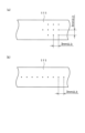
- FIG. 4 is a diagram showing an example of a hardness measurement position of a first member.
- FIG. 11A and 11B are diagrams showing an example of a joint structure in which a first ridge portion is composed of a straight portion and a curved portion.
- 10 is a diagram showing a schematic view of a straight line portion and a curved portion of a first ridge line portion when the joint structure of FIG. 9 is viewed from above.
- FIG. 11 shows an example of the shape of a hat member having a longer distance d than that of the hat member shown in FIG. 10 .
- FIG. 4 is a diagram illustrating a configuration example of a first member.
- FIG. 13 is a diagram for explaining an analytical model of simulation (1).
- FIG. 13 is a diagram showing the results of simulation (1).
- FIG. 13 is a diagram showing the results of simulation (1).
- FIG. 13 is a diagram showing the results of simulation (1).
- FIG. 13 is a diagram for explaining an analytical model of simulation (2).
- FIG. 13 is a diagram showing the results of simulation (2).
- FIG. 13 is a diagram for explaining an analytical model of simulation (3).
- FIG. 13 is a diagram showing the results of simulation (3).
- FIG. 13 is a diagram for explaining an analytical model of simulation (4).
- FIG. 13 is a diagram showing the results of simulation (4).
- FIG. 1 is a perspective view showing the schematic configuration of a joint structure 1 for an automobile frame member according to this embodiment.
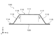
- FIG. 2 is a diagram showing a cross section perpendicular to the axial direction of the first member 100.
- FIG. 3 is a diagram showing the A-A cross section in FIG. 1. Note that the X direction, Y direction, and Z direction in this specification and the drawings are mutually perpendicular directions.
- the axial direction of the first member 100 refers to the direction in which the ridge line between the top plate and the vertical wall, which will be described later, continues
- the axial direction of the second member 200 refers to the direction in which the ridge line between the first wall surface and the second wall surface, which will be described later, continues.
- the joining structure 1 comprises a first member 100 and a second member 200.
- the first member 100 and the second member 200 are members extending in different directions, and the axial end of the first member 100 is joined to the second member 200.
- the means for joining the two members 100 and 200 is not particularly limited, and may be any known joining means such as spot welding, laser welding, or plasma welding, or an industrial adhesive.
- the first member 100 has a hat member 110 whose cross section perpendicular to the axial direction (Y direction) is hat-shaped, and a closing plate 120.
- the first member 100 is a hollow member whose cross section perpendicular to the axial direction is a closed cross section due to the joining of the hat member 110 and the closing plate 120. A detailed description of the hat member 110 will be given later.
- the second member 200 is a hollow member having a rectangular cylindrical shape, and has a first wall surface 201 and a second wall surface 202.
- the first wall surface 201 is a wall surface facing the end of the first member 100 in the axial direction (Y direction).
- the second wall surface 202 is a wall surface extending from the first wall surface 201 to the side opposite the first member 100 side.
- the first wall surface 201 and the second wall surface 202 are connected to each other, and a ridge portion 203 is formed between the first wall surface 201 and the second wall surface 202.
- the ridge portion 203 extends along the axial direction (X direction) of the second member 200.
- the first member 100 and the second member 200 described above are both skeletal members of an automobile body, and the joining structure 1 is applied to the locations where each skeletal member of the automobile body is joined in an approximately T-shape.
- the second member 200 is a side sill
- the first member 100 is a floor cross member or a center pillar
- the second member 200 is a side sill
- the first member 100 is a roof cross member
- the second member 200 is a roof side rail.
- the first member 100 is a side member (front side member or rear side member)
- the second member 200 is a bumper beam (front bumper beam or rear bumper beam).
- the X direction, the Y direction, and the Z direction respectively indicate the following directions.
- ⁇ Joint structure between floor cross member and side sill X direction vehicle length
- Y direction vehicle width
- Z direction vehicle height
- ⁇ Joint structure between centre pillar and side sill X direction vehicle length
- Y direction vehicle height
- Z direction vehicle width
- X direction vehicle length
- Y direction vehicle width
- Z direction vehicle height
- X direction vehicle width
- Y direction vehicle length
- Z direction vehicle height
- the first wall surface 201 facing the axial end of the first member 100 is the vehicle interior side wall surface of the side sill in the vehicle width direction.
- the second wall surface 202 extending from the first wall surface 201 to the opposite side to the first member 100 side refers to the wall surface extending from the vehicle interior side wall surface of the side sill in the vehicle width direction toward the vehicle exterior side in the vehicle width direction, and corresponds to the upper or lower surface of the side sill.
- the first wall surface 201 is the upper surface of the side sill.
- the second wall surface 202 is a wall surface that extends downward from the upper surface of the side sill, and corresponds to the wall surface of the side sill on the outer or inner side of the vehicle in the vehicle width direction.
- the first wall surface 201 is the vehicle interior side wall surface of the roof side rail in the vehicle width direction.
- the second wall surface 202 is the wall surface that extends from the vehicle interior side wall surface of the roof side rail in the vehicle width direction toward the vehicle exterior side in the vehicle width direction, and corresponds to the upper or lower surface of the roof side rail.
- the first wall surface 201 is the vehicle interior side wall surface in the vehicle length direction of the bumper beam.
- the second wall surface 202 is the wall surface that extends from the vehicle interior side wall surface in the vehicle length direction of the bumper beam toward the vehicle exterior side in the vehicle length direction, and corresponds to the upper or lower surface of the bumper beam.
- the overall length of the first member 100 and the overall length of the second member are changed as appropriate depending on the location of application of the joining structure 1 to the vehicle body, and are, for example, between 1000 and 3000 mm.
- the plate thickness of the first member 100 and the plate thickness of the second member 200 are changed as appropriate depending on the application location of the joining structure 1 on the vehicle body and the required load-bearing performance, and are, for example, 0.5 to 6.0 mm.
- the plate thickness of each member 100, 200 may be, for example, 0.8 mm or more, or 1.0 mm or more.
- the plate thickness of each member 100, 200 may be, for example, 4.0 mm or less, or 3.0 mm or less.
- the plate thickness of each member 100, 200 may be different from each other.
- the first member 100 and the second member 200 are made of a metal material such as steel, an aluminum alloy member, or a magnesium alloy member.
- the materials of the members 100 and 200 may be different from each other.
- the hat member 110 has a top plate 111, two vertical walls 112, 113, and two flanges 114, 115.
- the top plate 111 is a plate-like portion that extends in the longitudinal direction of the first member 100.
- the extension direction of the top plate 111 is the vehicle width direction when the first member 100 is applied to a skeleton member such as a cross member, the vehicle height direction when the first member 100 is applied to a skeleton member such as a center pillar, and the vehicle length direction when the first member 100 is applied to a skeleton member such as a side member.
- the two vertical walls 112, 113 are arranged opposite each other and are located between the top plate 111 and each of the two flanges 114, 115. Each of the two vertical walls 112, 113 is connected to the top plate 111, and ridges 116, 117 are formed between the two vertical walls 112, 113 and the top plate 111, respectively.
- the two ridges 116, 117 are formed in a straight line along the axial direction (Y direction) of the first member 100, and extend to the axial end of the first member 100 (the end on the second member 200 side).
- the two ridges 116, 117 sandwiched between the top plate 111 and the two vertical walls 112, 113 are sometimes referred to as the "first ridges”
- the ridge 203 of the second member 200 described above is sometimes referred to as the "second ridge”.
- the flanges 114, 115 are connected to the ends of the vertical walls 112, 113 opposite the connecting end of the top plate 111, and extend outward from each of the two vertical walls 112, 113.
- the length from the flanges 114, 115 to the top plate 111 in a direction perpendicular to the top plate 111 is changed as appropriate depending on the application location of the first member 100 to the vehicle body, but is set to, for example, 30 to 200 mm.
- the width of the top plate 111 is changed as appropriate depending on the application location of the joining structure 1 to the vehicle body, but is set to, for example, 30 to 250 mm.
- the axial end of the first member 100 (the end on the second member 200 side) is formed with a continuous flange 130 that extends outward from the top plate 111, the two first ridges 116, 117, and the two vertical walls 112, 113 of the hat member 110 toward the outside of the hollow portion.
- This continuous flange 130 is formed continuously over the entire area from one of the two vertical walls 112 to the ridge 116, the top plate 111, the ridge 117, and the other vertical wall 113.
- the continuous flange 130 is a flange in which the top plate extension portion 141 extending from the top plate 111 and the vertical wall extension portions 142, 143 extending from the two vertical walls 112, 113 are continuous.
- the top plate extension portion 141 and the vertical wall extension portion 142 are continuous via the connecting portion 144. Therefore, in this case, the flange including the top plate extension portion 141, the vertical wall extension portion 142, and the connecting portion 144 is a continuous flange. That is, in the example shown in FIG. 4(a), the top plate extension portion 141, the vertical wall extension portion 142, and the connecting portion 144 constitute the continuous flange 130.
- the shape of the tabletop extension 141 is different from that in FIG. 4(a), but in this example too, there is a connecting portion 144 including the corner R of the first ridge portion 116 between the tabletop extension 141 and the vertical wall extension 142, and the connecting portion 144 connects the tabletop extension 141 and the vertical wall extension 142.
- the tabletop extension 141, the vertical wall extension 142, and the connecting portion 144 form a continuous flange 130.
- the continuous flange 130 has a first plane 140 joined to the first wall surface 201 of the second member 200, and a second plane 150 joined to the second wall surface 202.
- the first plane 140 is the surface that contacts the first wall surface 201.
- the first plane 140 is formed by a top plate extension portion 141 extending from the top plate 111, vertical wall extension portions 142, 143 extending from the two vertical walls 112, 113, and connecting portions 144, 145 that connect each of the two vertical wall extension portions 142, 143 to the top plate extension portion 141.
- the second plane 150 is a surface that contacts the second wall surface 202 and is a surface that extends from the upper ends of the top plate extension portion 141 and the two connecting portions 144, 145 toward the second member 200.
- the first member 100 having the continuous flange 130 is formed so that the angle ⁇ (FIG. 2) between a plane perpendicular to the top plate 111 and each of the two vertical walls 112, 113 when viewed in a cross section perpendicular to the axial direction of the first member 100 satisfies 20° ⁇ 45°.
- the angle ⁇ is referred to as the vertical wall angle ⁇ .
- the vertical wall angle ⁇ is greater than 45°, there is a risk that the first member 100 will buckle early before it can fully exert its deformation resistance against the collision load from the second member 200 side.
- the vertical wall angle ⁇ is 45° or less, the occurrence of such early buckling of the first member 100 can be suppressed, thereby increasing the deformation resistance against the collision load from the second member 200 side and improving the load-bearing performance.
- a joint structure 1 having a first member 100 with a vertical wall angle ⁇ that satisfies 20° ⁇ 45° can suppress the occurrence of cracks in the first member 100 and can obtain excellent load-bearing performance.
- the vertical wall angle ⁇ is less than 20°, there is a risk that the connecting portions 144, 145 may break during the molding process of the continuous flange 130. Therefore, by setting the vertical wall angle ⁇ to 20° or more, it becomes easier to mold the continuous flange 130, and the first member 100 can be manufactured more easily.
- the vertical wall angle ⁇ be 25° or more.
- the hat member 110 has a symmetrical shape, and the angle between one of the two vertical walls 112 and the top plate 111, and the angle between the other vertical wall 113 and the top plate 111 are equal to each other, but the two vertical wall angles may be different from each other.
- each vertical wall angle ⁇ must satisfy 20° ⁇ 45°.
- the joint structure 1 the distance h (FIG. 3) between the second ridge 203 and the top plate 111 of the first member 100 in the direction perpendicular to the top plate 111 (Z direction) with the position of the second ridge 203 of the second member 200 as the reference (origin) satisfies -10 mm ⁇ h ⁇ 10 mm.
- the joint structure 1 is configured so that the absolute value of the length (Z direction length) from the second ridge 203 to the top plate 111 in the direction perpendicular to the top plate 111 is within 10 mm.
- the value of the distance h has a positive sign, it indicates that the top plate 111 is located on the negative side of the Z direction relative to the second ridge 203, and when the value of the distance h has a negative sign, it indicates that the top plate 111 is located on the positive side of the Z direction relative to the second ridge 203.
- the spacing h is preferably -7 mm or more, and more preferably -5 mm or more. From the same viewpoint, the spacing h is preferably 7 mm or less, and more preferably 5 mm or less.
- the second ridge portion 203 is a curved surface portion between the first wall surface 201 and the second wall surface 202, and the position of the second ridge portion 203 in the direction perpendicular to the tabletop 111 when calculating the distance h is the position of the intersection line between an imaginary plane extending from the first wall surface 201 and an imaginary plane extending from the second wall surface 202.
- the distance (length in the Z direction) between the second ridge 203 and the top plate 111 will vary depending on the measurement location.
- the above-mentioned distance h means the minimum distance between the second ridge 203 and the top plate 111.
- Figures 6 and 7 are diagrams showing an example of joint structure 1 where h ⁇ 0.
- the continuous flange 130 in this example also has extensions 141-143 extending from the top plate 111 and two vertical walls 112, 113, and is shaped such that there are no discontinuous parts across the top plate 111, the two vertical walls 112, 113, and the two ridges 116, 117.
- the first plane 140 is composed of the two vertical wall extensions 142, 143.
- this joining structure 1 is provided with a continuous flange 130 that is formed continuously from the vertical walls 112, 113 to the top plate 111 at the axial end of the first member 100.
- the vertical wall angle ⁇ satisfies 20° ⁇ 45°, and the distance h between the second ridge portion 203 and the top plate 111 satisfies -10mm ⁇ h ⁇ 10mm.
- joint structure 1 With this type of joint structure 1, distortion of the first ridges 116, 117 is unlikely to occur when a collision load is applied, making it possible to realize a highly rigid structure with excellent load-bearing performance. Furthermore, since the joint structure 1 is lighter or has the same weight as structures whose vertical wall angle ⁇ and spacing h do not satisfy the above ranges, it also has excellent weight efficiency in terms of load-bearing performance.
- the tensile strength of the steel is preferably 980 MPa or more.
- the effect of suppressing early yielding of the material is enhanced, and the load-bearing performance can be effectively improved.
- the joint structure 1 is compatible with high-strength steel plates, and is a useful structure for electric vehicles, for example, where the use of high-strength steel plates is being considered to improve the battery protection function.
- the tensile strength of the steel material is more preferably 1180 MPa or more, and even more preferably 1270 MPa or more.
- the tensile strength converted from the hardness of the top plate 111 measured in accordance with JIS Z 2244 at a test force F of 49.03 N or more using a hardness conversion table (SAE J 417) is regarded as the tensile strength of the material constituting the hat member 110.
- the method for measuring the hardness of the top plate 111 is as follows. First, a part of the top plate 111 is cut out as shown by the two-dot chain line area in FIG. 1, and the hardness of any 10 points determined as hardness measurement points as shown in FIG. 8(a) or FIG. 8(b) is measured. However, each hardness measurement point must be at least 3 mm apart from each other.
- the average value of the Vickers hardness of each hardness measurement point measured under these conditions is regarded as the hardness of the top plate 111, and the tensile strength corresponding to the hardness of the top plate 111 is calculated using the hardness conversion table (SAE J 417).
- the tensile strength calculated here is the tensile strength of the material constituting the hat member 110.
- the hat member 110 can be considered to be made of a material with a tensile strength of 980 MPa or more.
- the first ridges 116, 117 of the first member 100 described above are formed in a straight line up to the first wall surface 201 of the second member 200, but the first ridges 116, 117 may be composed of straight lines 116a, 117a and curved lines 116b, 117b as shown in Figures 9 and 10.
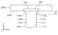
- Figure 10 is a top view of the joint structure 1 in Figure 9, and is a schematic diagram focusing on the straight lines and curved lines of the first ridges 116, 117. For this reason, some of the member shapes are not shown.
- curved portions 116b, 117b are located between the straight portions 116a, 117a of the two first ridges 116, 117 and the continuous flange 130. These curved portions 116b, 117b are curved so as to be convex toward the inside of the top plate 111. Therefore, the width of the top plate 111 gradually increases toward the second member 200 at the axial end of the first member 100.
- the collision load is transmitted to the straight line portions 116a, 117a of the first ridge portions 116, 117, thereby increasing the deformation resistance of the first member 100. Therefore, in order to transmit the load to the straight line portions 116a, 117a early when the collision load is input and obtain high deformation resistance from the initial stage of the collision, it is preferable that the distance d ( Figure 10) between the straight line portions 116a, 117a in the axial direction (Y direction) of the first member 100 and the second ridge portion 203 of the second member 200 is not excessively large.
- the distance d satisfies 0 ⁇ d ⁇ 20 mm.
- the distance d satisfies this range, high deformation resistance is obtained from the initial stage of the collision, and the amount of collision energy absorbed can be increased.
- the distance d is preferably 17 mm or less, and more preferably 15 mm or less.
- FIG. 11 shows an example of the shape of the hat member 110 in which the distance d is longer than that of the hat member 110 in FIG. 10.
- the distance d is increased as in FIG. 11, it is necessary to form the continuous flange 130 so that the width of the second plane 150 is also increased due to processing constraints.
- the space for joining the second plane 150 to the second member 200 also increases, which may require changes to the body structure around the joining space, or may make the joining itself difficult because the joining space cannot be secured.
- the distance d satisfies 0 ⁇ d ⁇ 20 mm.
- the position of the second ridge portion 203 in the axial direction (Y direction) of the first member 100 is the position of the intersection line between an imaginary plane extending the first wall surface 201 and an imaginary plane extending the second wall surface 202.
- the continuous flange 130 has the first plane 140 and the second plane 150, but at least a part of the first plane 140 and the first wall surface 201 do not have to be joined to each other. Even in this case, as long as the second plane 150 and the second wall surface 202 are joined, it is possible to obtain a joint structure 1 with excellent weight efficiency in load-bearing performance as described in the above embodiment. In other words, the continuous flange 130 only needs to have a joint surface that is joined to the second wall surface 202 of the second member 200.
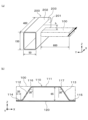
- the first member 100 described above is composed of a hat member 110 and a closing plate 120, but the configuration of the first member 100 may be, for example, as shown in FIG. 12.
- Figure 12(a) shows an example of a configuration in which a groove 118 is provided on the top plate 111 of the hat member 110.
- Figure 12(b) shows an example of a configuration in which an inflection portion 119 is provided on the vertical walls 112, 113 of the hat member 110.
- Figure 12(c) shows an example of a configuration in which the hat member 110 and another hat member 121 are joined by a flange.
- Figure 12(d) shows another example of a configuration in which two hat members 110, 122 are used.
- the second member 200 is not limited to the rectangular cylindrical member described above, but may be composed of, for example, a combination of a hat member and a closing plate, or a combination of two hat members.
- FIG. 13(a) shows a schematic diagram of the first member 100
- FIG. 13(b) shows a specific configuration of the first member 100.
- a continuous flange 130 as shown in FIG. 1 is formed at the end of the first member 100 on the second member 200 side, and the continuous flange 130 is joined to the first wall surface 201 and the second wall surface 202 of the second member 200.
- the main simulation conditions are set as follows: ⁇ Software name: LS-Dyna ⁇ Version: R9.3.1 ⁇ Mesh size: 2mm
- Element type Shell element developed by Belytschko-Wong-Chiang Material of hat member 110: Steel plate (tensile strength 1180 MPa, plate thickness 1.6 mm) Material of plate 120: Steel plate (tensile strength 270 MPa, plate thickness 0.8 mm) Material of the second member 200: Steel plate (tensile strength 1180 MPa, plate thickness 1.2 mm) ⁇ Vertical wall angle ⁇ : 0 ⁇ 60° ⁇ Distance h: -10 to 40mm Spacing d: 0 mm
- Boundary condition Both axial end faces of the second member 200 are completely restrained, and the axial end face of the first member 100 (the end face opposite to the second member side) is forcibly displaced by 2 mm in the direction of the arrow.
- Figure 14 shows the results of simulation (1), showing the change in maximum reaction force with changes in the spacing h and vertical wall angle ⁇ .
- the joint structure that satisfies -10 mm ⁇ h ⁇ 10 mm has a larger maximum reaction force and is superior in load-bearing performance compared to structures that fall outside this range.
- a joint structure that satisfies -10 mm ⁇ h ⁇ 10 mm is lighter than a structure with an absolute value of the interval h of 20 mm or more, yet has improved load-bearing performance, making it a structure with excellent weight efficiency in terms of load-bearing performance.
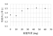
- FIG. 15 is a diagram showing the rate of increase in the maximum reaction force when the spacing h is 0 mm (i.e., the rate of improvement in load-bearing performance) when the maximum reaction force when the spacing h is 40 mm is used as the standard.
- the value on the vertical axis in FIG. 15 is the value obtained by dividing the maximum reaction force when the spacing h is 0 mm by the maximum reaction force when the spacing h is 40 mm.
- the vertical wall angle is 20° or more, the rate of improvement in load-bearing performance increases dramatically. That is, according to the results shown in FIG. 14 and FIG.
- a vertical wall angle of 20° or more effectively increases the maximum reaction force and enhances the effect of improving load-bearing performance. Furthermore, when the vertical wall angle is 25° or more, the effect of improving load-bearing performance is further enhanced, so it is preferable that the vertical wall angle is 25° or more.
- FIG. 16(a) shows the first member 100 in a schematic manner
- FIG. 16(b) shows a specific configuration of the first member 100.
- the continuous flange 130 shown in FIG. 1 is formed at the end of the first member 100 on the second member 200 side, and the continuous flange 130 is joined to the first wall surface 201 and the second wall surface 202 of the second member 200.
- a discontinuous flange is a flange in which the top plate extension 141 and the two vertical wall extensions 142 and 143 are not connected to each other, without the connecting parts 144 and 145 as shown in FIG. 1.
- the main simulation conditions are set as follows: ⁇ Software name: LS-Dyna ⁇ Version: R9.3.1 ⁇ Mesh size: 2mm
- Element type Shell element developed by Belytschko-Wong-Chiang
- Material of hat member 110 Steel plate (tensile strength 1180 MPa, plate thickness 1.6 mm)
- Material of plate 120 Steel plate (tensile strength 270 MPa, plate thickness 0.8 mm)
- Material of the second member 200 Steel plate (tensile strength 1180 MPa, plate thickness 1.2 mm) ⁇ Vertical wall angle ⁇ : 0° to 60° Spacing h: 5 mm Spacing d: 0 mm
- Boundary condition The axial end face of the first member 100 (the end face opposite to the second member side) is completely restrained, and the second member 200 is forcibly displaced by 40 mm in the direction of the arrow.
- Figure 17 shows the results of simulation (2).
- the presence or absence of "cracks" shown in Figure 17 refers to the presence or absence of locations where the plate thickness of the first member 100 has decreased by 15% or more compared to the initial plate thickness. If the simulation shows that there are locations where the plate thickness has decreased by 15% or more, it is determined that "cracks are present.”
- the joint structure that satisfies 20° ⁇ 45° has improved load-bearing performance compared to a joint structure where the vertical wall angle ⁇ is 60°, despite having the same weight, and is therefore a structure with excellent weight efficiency in terms of load-bearing performance.
- a joint structure that satisfies -10 mm ⁇ h ⁇ 10 mm and 20° ⁇ 45° exhibits high load-bearing performance against both collision loads input in the axial direction of the first member 100 and collision loads input in the axial direction of the second member 200.
- a joint structure in which the first member 100 is a floor cross member and the second member 200 is a side sill exhibits excellent load-bearing performance against both small overlap collisions and side collisions by having the spacing h and vertical wall angle ⁇ satisfy the above ranges.
- FIG. 18(a) shows a schematic diagram of the first member 100
- FIG. 18(b) shows a specific configuration of the first member 100.
- the continuous flange 130 shown in FIG. 1 is formed at the end of the first member 100 on the second member 200 side, and the continuous flange 130 is joined to the first wall surface 201 and the second wall surface 202 of the second member 200.
- the main simulation conditions are set as follows: ⁇ Software name: LS-Dyna ⁇ Version: R9.3.1 ⁇ Mesh size: 2mm
- Element type Shell element developed by Belytschko-Wong-Chiang Material of hat member 110: Steel plate (tensile strength 270 to 2000 MPa, plate thickness 1.6 mm) Material of plate 120: Steel plate (tensile strength 270 MPa, plate thickness 0.8 mm) Material of the second member 200: Steel plate (tensile strength 1180 MPa, plate thickness 1.2 mm) Vertical wall angle ⁇ : 30° Spacing h: 0 mm Spacing d: 0 mm
- Boundary condition Both axial end faces of the second member 200 are completely restrained, and the axial end face of the first member 100 (the end face opposite to the second member side) is forcibly displaced by 2 mm in the direction of the arrow.
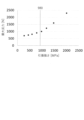
- Figure 19 shows the results of simulation (3). As shown in Figure 19, when the tensile strength is 980 MPa or more, the effect of increasing the load-bearing performance is greater than when the tensile strength is less than 980 MPa.
- FIG. 20(a) shows the first member 100 in a schematic manner
- FIG. 20(b) shows a specific configuration of the first member 100.
- the continuous flange 130 shown in FIG. 1 is formed at the end of the first member 100 on the second member 200 side, and the continuous flange 130 is joined to the first wall surface 201 and the second wall surface 202 of the second member 200.
- this simulation uses a model in which the first ridges 116, 117 are composed of straight line portions 116a, 117a and curved line portions 116b, 117b as shown in Figure 10. Simulations were performed using multiple models in which the distance d between the straight line portions 116a, 117a and the second ridge 203 was changed within a range of 5 to 60 mm.
- the main simulation conditions are set as follows: ⁇ Software name: LS-Dyna ⁇ Version: R9.3.1 ⁇ Mesh size: 2mm
- Element type Shell element developed by Belytschko-Wong-Chiang Material of hat member 110: Steel plate (tensile strength 1180 MPa, plate thickness 1.6 mm) Material of plate 120: Steel plate (tensile strength 270 MPa, plate thickness 0.8 mm) Material of the second member 200: Steel plate (tensile strength 1180 MPa, plate thickness 1.2 mm) Vertical wall angle ⁇ : 30° Spacing h: 5 mm ⁇ Distance d: 5-60mm
- Boundary condition The axial end face of the first member 100 (the end face opposite to the second member side) is completely restrained, and the second member 200 is forcibly displaced by 40 mm in the direction of the arrow.
- FIG. 21 shows the results of simulation (4).
- the average reaction force shown on the vertical axis of FIG. 21 is the average value of the reaction force generated in the first member 100 until the second member 200 is displaced 40 mm, and the higher this average reaction force is, the higher the energy absorption capacity of the structure is.
- the present invention can be applied to automobile body structures.
Landscapes
- Engineering & Computer Science (AREA)
- Mechanical Engineering (AREA)
- Chemical & Material Sciences (AREA)
- Combustion & Propulsion (AREA)
- Transportation (AREA)
- Body Structure For Vehicles (AREA)
Priority Applications (2)
| Application Number | Priority Date | Filing Date | Title |
|---|---|---|---|
| CN202480059593.0A CN121866200A (zh) | 2023-10-12 | 2024-10-11 | 汽车骨架构件的接合构造 |
| JP2025522263A JPWO2025079670A1 (https=) | 2023-10-12 | 2024-10-11 |
Applications Claiming Priority (2)
| Application Number | Priority Date | Filing Date | Title |
|---|---|---|---|
| JP2023177024 | 2023-10-12 | ||
| JP2023-177024 | 2023-10-12 |
Publications (1)
| Publication Number | Publication Date |
|---|---|
| WO2025079670A1 true WO2025079670A1 (ja) | 2025-04-17 |
Family
ID=95395853
Family Applications (1)
| Application Number | Title | Priority Date | Filing Date |
|---|---|---|---|
| PCT/JP2024/036385 Pending WO2025079670A1 (ja) | 2023-10-12 | 2024-10-11 | 自動車骨格部材の接合構造 |
Country Status (3)
| Country | Link |
|---|---|
| JP (1) | JPWO2025079670A1 (https=) |
| CN (1) | CN121866200A (https=) |
| WO (1) | WO2025079670A1 (https=) |
Cited By (1)
| Publication number | Priority date | Publication date | Assignee | Title |
|---|---|---|---|---|
| WO2026028615A1 (ja) * | 2024-07-30 | 2026-02-05 | 日本製鉄株式会社 | 自動車骨格部材および車体構造 |
Citations (4)
| Publication number | Priority date | Publication date | Assignee | Title |
|---|---|---|---|---|
| WO2015174353A1 (ja) * | 2014-05-14 | 2015-11-19 | 新日鐵住金株式会社 | ブランク及びプレス成形品の製造方法 |
| WO2016194963A1 (ja) * | 2015-06-01 | 2016-12-08 | 新日鐵住金株式会社 | プレス成形品、プレス成形方法、およびプレス成形装置 |
| WO2018174082A1 (ja) * | 2017-03-24 | 2018-09-27 | 新日鐵住金株式会社 | ハット部材およびその製造方法 |
| WO2023032953A1 (ja) * | 2021-09-03 | 2023-03-09 | 日本製鉄株式会社 | 構造部材及びその製造方法 |
-
2024
- 2024-10-11 WO PCT/JP2024/036385 patent/WO2025079670A1/ja active Pending
- 2024-10-11 JP JP2025522263A patent/JPWO2025079670A1/ja active Pending
- 2024-10-11 CN CN202480059593.0A patent/CN121866200A/zh active Pending
Patent Citations (4)
| Publication number | Priority date | Publication date | Assignee | Title |
|---|---|---|---|---|
| WO2015174353A1 (ja) * | 2014-05-14 | 2015-11-19 | 新日鐵住金株式会社 | ブランク及びプレス成形品の製造方法 |
| WO2016194963A1 (ja) * | 2015-06-01 | 2016-12-08 | 新日鐵住金株式会社 | プレス成形品、プレス成形方法、およびプレス成形装置 |
| WO2018174082A1 (ja) * | 2017-03-24 | 2018-09-27 | 新日鐵住金株式会社 | ハット部材およびその製造方法 |
| WO2023032953A1 (ja) * | 2021-09-03 | 2023-03-09 | 日本製鉄株式会社 | 構造部材及びその製造方法 |
Cited By (1)
| Publication number | Priority date | Publication date | Assignee | Title |
|---|---|---|---|---|
| WO2026028615A1 (ja) * | 2024-07-30 | 2026-02-05 | 日本製鉄株式会社 | 自動車骨格部材および車体構造 |
Also Published As
| Publication number | Publication date |
|---|---|
| JPWO2025079670A1 (https=) | 2025-04-17 |
| CN121866200A (zh) | 2026-04-14 |
Similar Documents
| Publication | Publication Date | Title |
|---|---|---|
| JP6703322B1 (ja) | 自動車骨格部材および電気自動車 | |
| CN108495777A (zh) | 车辆前部构造 | |
| CN114987627B (zh) | 一种电动汽车前地板结构及包括该前地板结构的电动汽车 | |
| WO2019035185A1 (ja) | バンパービーム及び車両 | |
| CN102791532A (zh) | 机动车用部件 | |
| US20240097256A1 (en) | Battery case of automobile and method for manufacturing the same | |
| JP2023030757A (ja) | 車体下部構造 | |
| EP3848273B1 (en) | Automobile structural member | |
| WO2025079670A1 (ja) | 自動車骨格部材の接合構造 | |
| WO2020050422A1 (ja) | 自動車構造部材 | |
| EP4230508A1 (en) | Vehicle body lower structure of automobile | |
| JP7376797B2 (ja) | 自動車骨格部材および電気自動車 | |
| JP6566173B1 (ja) | フロントピラーアウタ | |
| JP4764035B2 (ja) | 自動車パネル構造体 | |
| WO2026029065A1 (ja) | 自動車骨格部材 | |
| JP7727256B2 (ja) | 継手構造 | |
| JP7842371B2 (ja) | 自動車構造部材 | |
| WO2020085383A1 (ja) | 自動車骨格部材および電気自動車 | |
| JP6687179B1 (ja) | 自動車骨格部材および電気自動車 | |
| WO2026028615A1 (ja) | 自動車骨格部材および車体構造 | |
| CN207644329U (zh) | 一种汽车防撞梁结构及汽车 | |
| CN119840732B (zh) | 机舱前部传力结构及车辆 | |
| CN205440240U (zh) | 一种带有吸能结构的车架 | |
| JP6766978B1 (ja) | 自動車構造部材 | |
| KR102257663B1 (ko) | 자동차의 충격 흡수 부재 및 사이드 멤버 |
Legal Events
| Date | Code | Title | Description |
|---|---|---|---|
| ENP | Entry into the national phase |
Ref document number: 2025522263 Country of ref document: JP Kind code of ref document: A |
|
| WWE | Wipo information: entry into national phase |
Ref document number: 2025522263 Country of ref document: JP |
|
| 121 | Ep: the epo has been informed by wipo that ep was designated in this application |
Ref document number: 24877264 Country of ref document: EP Kind code of ref document: A1 |