WO2023032953A1 - 構造部材及びその製造方法 - Google Patents
構造部材及びその製造方法 Download PDFInfo
- Publication number
- WO2023032953A1 WO2023032953A1 PCT/JP2022/032517 JP2022032517W WO2023032953A1 WO 2023032953 A1 WO2023032953 A1 WO 2023032953A1 JP 2022032517 W JP2022032517 W JP 2022032517W WO 2023032953 A1 WO2023032953 A1 WO 2023032953A1
- Authority
- WO
- WIPO (PCT)
- Prior art keywords
- structural member
- lower mold
- flange
- flange portion
- mold
- Prior art date
Links
- 238000004519 manufacturing process Methods 0.000 title claims abstract description 68
- 238000000034 method Methods 0.000 title claims abstract description 32
- 239000000463 material Substances 0.000 claims abstract description 140
- 238000000465 moulding Methods 0.000 claims abstract description 93
- 230000008569 process Effects 0.000 claims description 28
- 229910052751 metal Inorganic materials 0.000 claims description 22
- 239000002184 metal Substances 0.000 claims description 22
- 230000009467 reduction Effects 0.000 claims description 19
- 229910000831 Steel Inorganic materials 0.000 claims description 18
- 239000010959 steel Substances 0.000 claims description 18
- 238000010438 heat treatment Methods 0.000 claims description 9
- 230000007246 mechanism Effects 0.000 claims description 9
- 238000003825 pressing Methods 0.000 claims description 6
- 239000002994 raw material Substances 0.000 claims description 5
- 238000002360 preparation method Methods 0.000 abstract description 5
- 235000019589 hardness Nutrition 0.000 description 27
- 230000000052 comparative effect Effects 0.000 description 19
- 238000012360 testing method Methods 0.000 description 12
- 238000010586 diagram Methods 0.000 description 10
- 238000009826 distribution Methods 0.000 description 7
- 238000005336 cracking Methods 0.000 description 6
- 238000009966 trimming Methods 0.000 description 6
- 230000037303 wrinkles Effects 0.000 description 6
- 239000000047 product Substances 0.000 description 5
- 229910000838 Al alloy Inorganic materials 0.000 description 4
- 238000013461 design Methods 0.000 description 3
- 230000000694 effects Effects 0.000 description 3
- 238000007796 conventional method Methods 0.000 description 2
- 238000005520 cutting process Methods 0.000 description 2
- 230000007423 decrease Effects 0.000 description 2
- 230000004048 modification Effects 0.000 description 2
- 238000012986 modification Methods 0.000 description 2
- 238000007545 Vickers hardness test Methods 0.000 description 1
- 230000005540 biological transmission Effects 0.000 description 1
- 230000008859 change Effects 0.000 description 1
- 239000012141 concentrate Substances 0.000 description 1
- 230000003993 interaction Effects 0.000 description 1
- 239000013067 intermediate product Substances 0.000 description 1
- 238000011835 investigation Methods 0.000 description 1
- 238000003698 laser cutting Methods 0.000 description 1
- 230000000630 rising effect Effects 0.000 description 1
- 238000004088 simulation Methods 0.000 description 1
- XLYOFNOQVPJJNP-UHFFFAOYSA-N water Substances O XLYOFNOQVPJJNP-UHFFFAOYSA-N 0.000 description 1
Images


Classifications
-
- B—PERFORMING OPERATIONS; TRANSPORTING
- B21—MECHANICAL METAL-WORKING WITHOUT ESSENTIALLY REMOVING MATERIAL; PUNCHING METAL
- B21D—WORKING OR PROCESSING OF SHEET METAL OR METAL TUBES, RODS OR PROFILES WITHOUT ESSENTIALLY REMOVING MATERIAL; PUNCHING METAL
- B21D22/00—Shaping without cutting, by stamping, spinning, or deep-drawing
- B21D22/20—Deep-drawing
- B21D22/26—Deep-drawing for making peculiarly, e.g. irregularly, shaped articles
Definitions
- the present disclosure relates to structural members for automobiles and methods of manufacturing the same.
- a car is made up of many structural members.
- Structural members include, for example, pillars, side members, side sills, cross members, floor panels, roof panels, and the like.
- a structural member is manufactured, for example, by pressing a metal plate.
- Patent Literatures 1 to 3 disclose manufacturing methods for forming a metal plate into a structural member using a mold including an upper mold and a lower mold.
- Patent Document 1 In the manufacturing method of Patent Document 1, first, a metal plate is placed on a lower mold, and a predetermined region of this metal plate is pressed by a pad. Next, the upper mold is brought closer to the lower mold, and the metal plate is sandwiched between the upper mold and the lower mold while one longitudinal edge of the metal plate is moved in-plane to form a structural member. Patent Document 1 exemplifies a center pillar as a structural member manufactured by this manufacturing method.
- Patent Document 2 discloses a manufacturing method suitable for structural members such as side members, side sills, and cross members.
- the structural member to be manufactured in Patent Document 2 has a substantially hat-shaped cross section. That is, the structural member includes a top plate, two vertical walls and two flanges. The longitudinal ends of the structural members are provided with outward flanges rising from the top plate and each vertical wall.
- the outward flange and other portions are formed by a common lower mold.
- the forming of the structural member is started in such a manner that at least the region of the metal plate that will become the outward flange and the region in the vicinity thereof are separated from the top surface of the lower die.
- Patent Document 3 discloses a manufacturing method for a structural member having a T-shape (T-shaped part) such as a cross member.
- the T-shaped component includes a top plate having a T shape, a vertical wall continuous with the top plate, and a flange continuous with the lower end of the vertical wall.
- the top plate includes vertical sides and horizontal sides connected to the vertical sides.
- the manufacturing method of Patent Document 3 includes a first forming step of forming a metal plate into an intermediate-shaped part, a trimming step of trimming the intermediate-shaped part to obtain a trimmed part, and a mold including an upper mold and a lower mold. and a second forming step of forming the trimming component into a T-shaped component.
- a convex portion is formed on a portion of the top plate adjacent to the horizontal side of the vertical side.
- the curved R portion is formed so as to lift the connecting portion between the portion of the vertical wall that is continuous with the horizontal side portion of the top plate and the flange. The convex portion and the curved portion are crushed by the upper mold in the second molding step.
- the flange that continues to the lower end of the vertical wall is used, for example, as a first flange that joins the structural member to the floor panel.
- the lateral sides of the top plate and the portions of the vertical walls that are continuous with the lateral sides of the top plate are used, for example, as second flanges that join the structural member to the side sill.
- the horizontal side of the top plate and the portion of the vertical wall that is continuous with the horizontal side of the top plate have a substantially L shape when viewed from the side of the structural member.
- cracks may occur in the second flange.
- a joint structure that has a T-shape in plan view (T-shaped joint structure)
- the corner R portion can be formed relatively sharply, the degree of freedom in spatial connection with other parts increases, resulting in dimensional restrictions in design.
- the curvature radius of the corner R portion is 20.0 mm or less, the edge of the portion of the second flange extending in the height direction of the structural member and the Cracks are likely to occur at the connecting portion between the first flange and the second flange. Cracks in the second flange are particularly likely to occur when a structural member is formed from a steel plate with high tensile strength.
- strain concentration occurs because the aluminum alloy plate has a small uniform elongation. A sharp decrease in plate thickness locally occurs in a part, and cracks are likely to occur.
- An object of the present disclosure is to suppress the occurrence of cracks in flanges when manufacturing structural members for automobiles. Another object of the present disclosure is to eliminate the need for intermediate trimming of flanges when manufacturing structural members for automobiles. Furthermore, the present disclosure provides a structural member such as an integral T-shaped joint structure that has high strength, a small curvature radius of the corner R portion, and few dimensional restrictions in design, which has been long desired as a structural member for automobiles. is the subject.
- the manufacturing method according to the present disclosure is a manufacturing method for structural members for automobiles.
- the manufacturing method includes a preparation step of preparing a material made of a metal plate, and a molding step of molding the material into a structural member using a mold.
- the structural member includes a member body, a first flange and a second flange.
- the member main body includes a top plate and vertical walls.
- the top plate has two sides. The two sides extend longitudinally of the structural member. The two sides are across the width of the structural member.
- a vertical wall is connected to each of the sides via a ridge.
- a first flange is connected to the vertical wall on the opposite side of the top plate and extends from the vertical wall in the width direction of the structural member.
- the second flange is provided continuously at the end of the member body in the longitudinal direction.
- the second flange includes a horizontal flange portion and a vertical flange portion.
- the lateral flange portion protrudes from the top plate in the width direction of the structural member.
- the vertical flange portion is connected to the end portion of the horizontal flange portion on the side of the member main body via the ridgeline portion, and extends from the horizontal flange portion to the first flange.
- the mold includes an upper mold, a first lower mold for molding the member main body and the first flange, and a second lower mold for molding the second flange.
- the first lower mold is arranged to face the upper mold.
- the second lower mold is arranged next to the first lower mold so as to face the upper mold.
- the molding process includes a first step in which the material is sandwiched between the upper mold and the first lower mold while the material is not sandwiched between the upper mold and the second lower mold, and after the first step, the upper mold and the second lower mold. and a second step of sandwiching the material between and forming the second flange.
- the manufacturing method of the automotive structural member according to the present disclosure it is possible to suppress the occurrence of cracks in the flange. Further, according to the method of manufacturing a structural member for an automobile according to the present disclosure, it is possible to eliminate the intermediate trimming process of the flange. Furthermore, according to the present disclosure, there is provided a structural member such as an integral T-shaped joint structure that has high strength, a small curvature radius of the corner R portion, and few dimensional restrictions in design, which has been long desired as a structural member for automobiles. can do.
- FIG. 1 is a perspective view of a structural member according to a first embodiment
- FIG. 2 is a cross-sectional view of the structural member shown in FIG. 1
- FIG. 3A is a schematic diagram for explaining the manufacturing method of the structural member.
- FIG. 3B is a schematic diagram for explaining the manufacturing method of the structural member.
- FIG. 3C is a schematic diagram for explaining the manufacturing method of the structural member.
- FIG. 3D is a schematic diagram for explaining the manufacturing method of the structural member.
- FIG. 3E is a schematic diagram for explaining the method of manufacturing the structural member.
- FIG. 3F is a schematic diagram for explaining the manufacturing method of the structural member.
- FIG. 3G is a schematic diagram for explaining the manufacturing method of the structural member.
- FIG. 3A is a schematic diagram for explaining the manufacturing method of the structural member.
- FIG. 3B is a schematic diagram for explaining the manufacturing method of the structural member.
- FIG. 3C is a schematic diagram for explaining the manufacturing method of the structural member.
- FIG. 3H is a schematic diagram for explaining the method of manufacturing the structural member.
- FIG. 3I is a schematic diagram for explaining the manufacturing method of the structural member.
- 4 is a partially enlarged view of the structural member shown in FIG. 1;
- FIG. 5 is a partially enlarged view of the structural member shown in FIG. 1;
- FIG. FIG. 6 is a perspective view of a structural member according to the second embodiment.
- FIG. 7 is a perspective view of a structural member according to a modification of the second embodiment;
- FIG. 8 is a graph obtained by analysis, and is a graph showing the relationship between the distance from the edge of the vertical flange portion included in the structural member from the edge on the side of the horizontal flange portion and the plate thickness reduction rate.
- the manufacturing method according to the embodiment is a manufacturing method for structural members for automobiles.
- the manufacturing method includes a preparation step of preparing a material made of a metal plate, and a molding step of molding the material into a structural member using a mold.
- the structural member includes a member body, a first flange and a second flange.
- the member main body includes a top plate and vertical walls.
- the top plate has two sides. The two sides extend longitudinally of the structural member. The two sides are across the width of the structural member.
- a vertical wall is connected to each of the sides via a ridge.
- a first flange is connected to the vertical wall on the opposite side of the top plate and extends from the vertical wall in the width direction of the structural member.
- the second flange is provided continuously at the end of the member body in the longitudinal direction.
- the second flange includes a horizontal flange portion and a vertical flange portion.
- the lateral flange portion protrudes from the top plate in the width direction of the structural member.
- the vertical flange portion is connected to the end portion of the horizontal flange portion on the side of the member main body via the ridgeline portion, and extends from the horizontal flange portion to the first flange.
- the mold includes an upper mold, a first lower mold for molding the member main body and the first flange, and a second lower mold for molding the second flange.
- the first lower mold is arranged to face the upper mold.
- the second lower mold is arranged next to the first lower mold so as to face the upper mold.
- the molding process includes a first step in which the material is sandwiched between the upper mold and the first lower mold while the material is not sandwiched between the upper mold and the second lower mold, and after the first step, the upper mold and the second lower mold. and a second step of sandwiching the material between and forming the second flange (first configuration).
- a first lower mold for forming the member main body and the first flange, and a second lower mold for forming the second flange continuous to the longitudinal end of the member main body and to form a structural member from the material In the first molding step, the material is sandwiched between the upper mold and the first lower mold, while the material is not sandwiched between the upper mold and the second lower mold. That is, the portion of the material that will become the second flange is not restrained by the mold until the middle of the molding. As a result, the material flows in the portion of the material that will become the second flange.
- the material mainly flows from the horizontal flange portion continuous to the top plate of the member main body to the vertical flange portion connected to the horizontal flange portion and extending to the first flange. Therefore, it is possible to suppress the occurrence of cracks at the edge of the vertical flange portion and the connecting portion between the vertical flange portion and the first flange.
- the mold may further include a pad.
- the first step after pressing the material with the pad, it is preferable to clamp the material between the upper mold and the first lower mold (second configuration).
- the material in the first step of molding, after the material is pressed by the pad, the material is sandwiched between the upper mold and the first lower mold. As a result, when the material is formed into a structural member, it is possible to prevent the material from being displaced.
- the upper mold is formed in the first step.
- the first lower mold and the second lower mold are brought relatively close to each other, the first lower mold may precede the second lower mold and hold the material between the upper mold and the first lower mold.
- the second step by bringing the upper mold holding the material together with the first lower mold closer to the second lower mold, the step disappears and the second lower mold clamps the material between the upper mold and the upper mold. It can be clamped.
- the size of the step before the start of the first step is preferably equal to or greater than the plate thickness of the material and equal to or less than 5.0 times the plate thickness (third configuration).
- the second lower mold for forming the second flange is formed prior to the second lower mold.
- the first lower mold sandwiches the material with the upper mold. If this step is too small, the portion of the material that will become the second flange is restrained early by the second lower mold, and the flow of the material becomes insufficient. Cracks are likely to occur at the connecting portion with the first flange. On the other hand, if the step is too large, wrinkles are likely to occur at the boundary between the lateral flange portion of the second flange and the top plate of the member body.
- the step is set to an appropriate size. That is, the size of the step is greater than or equal to the plate thickness of the material and less than or equal to 5.0 times the plate thickness. Therefore, it is possible to suppress the occurrence of cracks and wrinkles in the second flange and its vicinity.
- the first lower mold may be configured to be liftable by a cushion mechanism.
- the upper mold in the molding step, the upper mold can be lowered toward the first lower mold and the second lower mold (fourth configuration).
- the manufacturing method according to any one of the first to fourth configurations may further include a preforming step of forming an intermediate molded product from the metal plate.
- the intermediate molded product in the molding step, can be used as a material to mold a structural member from the material (fifth configuration).
- the manufacturing method according to any one of the first to fifth configurations may further include a heating step of heating the raw material.
- the material heated in the heating step can be formed into a structural member (sixth configuration).
- the metal plate forming the raw material may be a steel plate having a tensile strength of 590 MPa or more (seventh configuration).
- a structural member is a structural member for an automobile.
- the structural member includes a member body, a first flange and a second flange.
- the member main body includes a top plate and vertical walls.
- the top plate has two sides. The two sides extend longitudinally of the structural member. The two sides are across the width of the structural member.
- a vertical wall is connected to each of the sides via a ridge.
- a first flange is connected to the vertical wall on the opposite side of the top plate and extends from the vertical wall in the width direction of the structural member.
- the second flange is provided continuously at the end of the member body in the longitudinal direction.
- the second flange includes a horizontal flange portion and a vertical flange portion.
- the lateral flange portion protrudes from the top plate in the width direction of the structural member.
- the vertical flange portion is connected to the member main body side end portion of the horizontal flange portion via the ridgeline portion, and extends from the horizontal flange portion to the first flange.
- the length of the region satisfying the above formula (1) is 2.0 times or more and 6.0 times the thickness of the top plate It is below. This means that the plate thickness distribution at the edge of the vertical flange portion is relatively uniform. In this case, when the structural member is used, stress concentration on the plate thickness reduction portion at the edge of the vertical flange portion is less likely to occur, and cracking from the edge of the vertical flange portion can be suppressed. That is, the structural member can be endowed with excellent durability.
- the length of the region having Vickers hardness HV [HV] that satisfies the following formula (2) at the edge of the vertical flange is 5.0 times the thickness of the top plate It may be 10.0 times or less (ninth configuration).
- HV Tmax [HV] is the Vickers hardness of the portion having the maximum thickness reduction rate Tmax in the edge of the vertical flange portion.
- HV and HV Tmax are the Vickers hardnesses at a test force of 294.2N.
- the length of the region satisfying the above formula (2) is 5.0 times or more and 10.0 times or less the plate thickness of the top plate. In some cases, it means that the hardness distribution at the edge of the vertical flange portion is relatively uniform. In this case, stress concentration is less likely to occur at the edge of the vertical flange portion, and the occurrence of cracks can be suppressed. That is, the structural member can be endowed with excellent durability.
- the average value of Vickers hardness measured at 30 locations separated by the thickness of the top plate or more on the surface of the vertical flange portion is 300.0 Hv or more
- the standard deviation of Vickers hardness may be 70.0 Hv or less (tenth configuration).
- the Vickers hardness at this time is the Vickers hardness at a test force of 10 kgf (98.07 N).
- the structural member according to any one of the eighth to tenth configurations may be made of a steel plate having a tensile strength of 590 MPa or more (eleventh configuration).
- the ridgeline portion may include a corner portion extending from the top plate toward the lateral flange portion.
- the corner portion has, for example, a radius of curvature of 20.0 mm or less in plan view of the structural member (twelfth configuration).
- the crossing angle between the vertical wall and the vertical flange portion, which are respectively continuous with the ridgeline portion can be, for example, a substantially right angle.
- the structural member can be made excellent in space efficiency. In other words, it is possible to increase the degree of freedom of spatial interaction with other parts, and reduce dimensional restrictions in designing structural members or other parts. In addition, even if the area where the structural member is arranged is narrow, the load-transmitting ability of the structural member can be ensured.
- the vertical flange portion can receive the load on its surface, and the load is transferred from the vertical flange portion to the member body. easier to transmit. Therefore, the structural member can exhibit good transferability of loads in the longitudinal direction.
- FIG. 1 is a perspective view of a structural member 10 according to the first embodiment.
- Structural member 10 is used as a structural member for an automobile.
- the structural member 10 is typically a frame extending in the left-right direction of the automobile.
- the structural member 10 is, for example, a cross member arranged on or behind the floor panel, a cross extension provided at the end of the cross member, or the like.
- the structural member 10 includes a member body 11, two first flanges 12 and a second flange 13.
- the member body 11 includes a top plate 111 and two vertical walls 112.
- the top plate 111 and each vertical wall 112 substantially extend in the longitudinal direction of the structural member 10 (horizontal direction of the vehicle).
- the top plate 111 includes two side portions 111a. These side portions 111a extend in the longitudinal direction of the structural member 10, respectively. The two side portions 111a face each other in the width direction of the structural member 10 (the longitudinal direction of the vehicle). A vertical wall 112 is connected to each of the side portions 111 a via the ridge line portion 14 . The ridgeline portion 14 extends from the member main body 11 over the second flange 13 .
- FIG. 2 is a cross-sectional view (II-II cross-sectional view) of the structural member 10.
- FIG. 2 two vertical walls 112 face each other in the width direction of structural member 10 .
- Each of the vertical walls 112 extends generally in the height direction of the structural member 10 (vertical direction of the automobile) when the structural member 10 is viewed in cross section.
- a ridgeline portion 14 continuous with each vertical wall 112 is substantially arcuate in a cross-sectional view of the structural member 10 .
- the first flange 12 is connected to the vertical wall 112 on the opposite side of the top plate 111 .
- Each of the first flanges 12 is connected to the lower end of the vertical wall 112 in the paper plane of FIG.
- Each first flange 12 is connected to the vertical wall 112 via a ridgeline portion 15 .
- the ridgeline portion 15 is substantially arcuate in cross-sectional view of the structural member 10 .
- the first flange 12 protrudes from the vertical wall 112 in the width direction of the structural member 10 .
- the first flange 12 is fixed, for example, to the upper or lower surface of a floor panel of an automobile.
- Each of the first flanges 12 extends substantially in the longitudinal direction of the structural member 10, similar to the top plate 111 and the vertical wall 112. As shown in FIG.
- Each first flange 12 has an open edge 12a.
- the second flange 13 is provided continuously with one end of the member main body 11 in the longitudinal direction of the structural member 10 .
- the second flange 13 is also continuous with the two first flanges 12 .
- the second flange 13 is fixed, for example, to a side sill of a motor vehicle.
- the second flange 13 includes a horizontal flange portion 131 and two vertical flange portions 132 .
- the lateral flange portion 131 is provided continuously with the top plate 111 of the member main body 11 .
- the lateral flange portion 131 is continuous with one longitudinal end portion of the top plate 111 .
- the lateral flange portion 131 is positioned substantially or substantially on the same plane as the top plate 111, for example.
- the lateral flange portion 131 may be flush with the top plate 111 or may be slightly inclined with respect to the top plate 111 .
- the lateral flange portion 131 protrudes from the top plate 111 in the width direction of the structural member 10 . That is, the length of the lateral flange portion 131 is greater than the length of the top plate 111 in the width direction of the structural member 10 .
- the lateral flange portion 131 and the top plate 111 form a substantially T-shape when the structural member 10 is viewed from above.
- the lateral flange portion 131 is connected to the top plate 111 by corner portions 141 included in each of the ridgeline portions 14 on both sides of the top plate 111 .
- Each corner portion 141 extends from the top plate 111 toward the lateral flange portion 131 .
- Each corner portion 141 has a substantially arc shape when the structural member 10 is viewed from above.
- the radius of curvature of each corner portion 141 is, for example, 20.0 mm or less in plan view of the structural member 10 .
- the amount of protrusion (flange length) of the horizontal flange portion 131 from the top plate 111 is, for example, 25.0 mm or less.
- Each of the vertical flange portions 132 is connected to the end portion 131a of the horizontal flange portion 131 on the member main body 11 side via the ridgeline portion 14 .
- the end portion 131 a is the end portion of the lateral flange portion 131 that protrudes from the top plate 111 to both sides in the width direction, on the side of the member main body 11 .
- Each vertical flange portion 132 is connected to the horizontal flange portion 131 by a ridgeline portion 14 extending from the member body 11 to the second flange 13 .
- Each of the vertical flange portions 132 extends from the horizontal flange portion 131 to the first flange 12 . That is, each vertical flange portion 132 extends generally in the height direction of the structural member 10 from the end portion 131 a of the horizontal flange portion 131 toward the first flange 12 .
- Each vertical flange portion 132 is integrated with the horizontal flange portion 131 , the vertical wall 112 of the member main body 11 , and the first flange 12 .
- a corner portion between the vertical flange portion 132 and the vertical wall 112 has, for example, a radius of curvature of 20.0 mm or less.
- Each vertical flange portion 132 has an open edge 132a.
- Edge 132 a extends generally in the height direction of structural member 10 .
- An end edge 132a of each vertical flange portion 132 is connected to a side edge 131b of the horizontal flange portion 131 via a connection edge 161 .
- the edge 132a of each vertical flange portion 132 is connected to the edge 12a of the first flange 12 via a connection edge 162.
- the connecting edges 161 and 162 are substantially arc-shaped when the structural member 10 is viewed from the side.
- FIGS. 3A to 3I are schematic diagrams for explaining the method of manufacturing the structural member 10.
- the method of manufacturing the structural member 10 includes the steps of preparing a material M and molding the material M into the structural member 10 .
- a material M made of a metal plate is prepared.
- the material M is, for example, a blank that is punched into a shape in which the structural member 10 (FIGS. 1 and 2) is developed.
- the metal plate forming the material M is, for example, a steel plate. This steel plate has, for example, a tensile strength of 590 MPa or more.
- the steel plate may have a tensile strength of 780 MPa or more, or may have a tensile strength of 980 MPa or more.
- the plate thickness of the material M is, for example, 1.0 mm or more and 5.0 mm or less.
- FIGS. 3B-3D the molding process uses a mold 20 to shape the material M into the structural member 10 (FIGS. 1 and 2).
- FIG. 3B is a perspective view of the mold 20.
- FIG. 3C is a lateral cross-sectional view (IIIC-IIIC cross-sectional view) of the mold 20.
- FIG. 3D is a longitudinal sectional view (IIID-IIID sectional view) of the mold 20.
- the mold 20 includes a first lower mold 21, a second lower mold 22, two upper molds 23, and a pad 24.
- the lower dies 21 and 22 are punches, and the upper die 23 is a die corresponding to the lower dies 21 and 22 .
- the lower molds 21 and 22 are placed facing the upper mold 23 and the pad 24 .
- the lower molds 21 and 22 are arranged below the upper mold 23 and the pad 24, for example.
- the first lower mold 21, the second lower mold 22, the upper mold 23, and the pad 24 are attached to, for example, a known press machine (not shown).
- the first lower mold 21 mainly forms the member body 11 and the first flange 12 (FIGS. 1 and 2).
- the first lower mold 21 is configured to be movable up and down by a cushion mechanism 25 .
- the cushion mechanism 25 may be one commonly used in presses, and includes, for example, a die cushion, cushion pins, and the like.
- the first lower mold 21 has a molding surface 211.
- the molding surface 211 has an upwardly convex shape.
- Molding surface 211 includes a top surface 211a, two side surfaces 211b, and two flange surfaces 211c.
- the top surface 211 a is an upward surface facing the pad 24 .
- the two side surfaces 211b are arranged on either side of the top surface 211a.
- the flange surfaces 211c are connected to the lower ends of the side surfaces 211b and protrude sideways from the side surfaces 211b.
- the second lower mold 22 is a separate mold from the first lower mold 21.
- the second lower mold 22 is arranged next to the first lower mold 21 in the longitudinal direction of the mold 20 .
- the second lower mold 22 mainly forms the second flange 13 (FIGS. 1 and 2).
- the second lower mold 22 has a molding surface 221 .
- the molding surface 221 of the second lower mold 22 includes a top surface 221a and side surfaces 221b.
- the top surface 221 a is an upward surface facing the pad 24 .
- the side surface 221b is connected to the top surface 221a on the first lower mold 21 side and extends downward from the top surface 221a.
- the molding surface 221 of the second lower mold 22 is positioned below the molding surface 211 of the first lower mold 21 . More specifically, since the top surface 221a of the second lower mold 22 is located below the top surface 211a of the first lower mold 21, there is a step between the top surfaces 211a, 221a. In addition, the lower end of the side surface 221b of the second lower mold 22 is located below the flange surface 211c of the first lower mold 21, and the side surface 221b of the second lower mold 22 and the flange surface 211c of the first lower mold 21 are positioned below each other.
- the step size S between the molding surface 211 of the first lower mold 21 and the molding surface 221 of the second lower mold 22 is preferably equal to or greater than the plate thickness of the material M.
- the size S of the step is, for example, 5.0 times or less the plate thickness of the material M.
- the step size S is substantially the same as the stroke of the cushion mechanism 25 (cushion stroke).
- the molding surface 231 of the upper mold 23 has a shape corresponding to the molding surface 211 of the first lower mold 21 and the molding surface 221 of the second lower mold 22.
- a pad 24 is arranged between the upper molds 23 .
- the upper die 23 and the pad 24 are attached to, for example, a slide that can move up and down in a press (not shown).
- the pad 24 is connected to the slide via, for example, a stretchable elastic member 26 .
- the mold 20 configured as described above is used to mold the material M into the structural member 10 (FIGS. 1 and 2).
- the molding process includes a first process and a second process.
- the first step the material M is sandwiched between the upper mold 23 and the first lower mold 21 while the material M is not sandwiched between the upper mold 23 and the second lower mold 22 .
- the second step the material M is sandwiched between the upper mold 23 and the second lower mold 22 to form the second flange 13 (FIGS. 1 and 2).
- Each step will be specifically described below.
- the material M on the first lower mold 21 is first pressed by the pad 24 as shown in FIG. 3E. That is, the material M is sandwiched between the top surface 211 a of the first lower mold 21 and the pad 24 .
- the top surface 221a of the second lower mold 22 is positioned slightly lower than the top surface 211a of the first lower mold 21, the material M is separated between the top surface 221a of the second lower mold 22 and the pad 24. not pinched.
- the slide of the press (not shown) is further lowered to bring the upper mold 23 closer to the lower molds 21 and 22.
- the elastic member 26 connecting the pad 24 to the slide is contracted, and the upper mold 23 is lowered relative to the pad 24. .
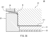
- the material M is pressed by the upper mold 23 and the first lower mold 21, as shown in FIGS. 3F and 3G.
- a step is formed in advance between the molding surface 211 of the first lower mold 21 and the molding surface 221 of the second lower mold 22 . Therefore, when the upper mold 23 is brought closer to the lower molds 21 and 22 , the first lower mold 21 clamps the material M together with the upper mold 23 ahead of the second lower mold 22 . When the material M is pressed by the upper mold 23 and the first lower mold 21, the second lower mold 22 does not press the material M. At this point, a gap exists between the material M and the second lower mold 22 .
- the material M is formed into the structural member 10 when the upper die 23 reaches the bottom dead center.
- a portion of the material M pressed between the pad 24 and the top surface 211 a of the first lower mold 21 becomes the top plate 111 of the member body 11 .
- a portion of the material M pressed between the upper mold 23 and the side surface 211 b of the first lower mold 21 becomes the vertical wall 112 of the member body 11 .
- a portion of the material M pressed between the upper mold 23 and the flange surface 211 c of the first lower mold 21 becomes the first flange 12 .
- a portion of the material M pressed between the pad 24 and the top surface 221 a of the second lower mold 22 mainly becomes the lateral flange portion 131 of the second flange 13 .
- a portion of the material M pressed between the upper mold 23 and the side surface 221 b of the second lower mold 22 mainly becomes the vertical flange portion 132 of the second flange 13 .
- each vertical flange portion 132 includes a deformation region R1.
- the deformation region R1 extends from the R stop of the connection edge 161 connecting the horizontal flange portion 131 and the vertical flange portion 132 (on the side of the vertical flange portion 132) to the R stop of the connection edge 162 connecting the vertical flange portion 132 and the first flange 12. (vertical flange portion 132 side).
- the entire deformation region R1 has a plate thickness reduction rate T [%] that satisfies the following formula (1). 0.9 ⁇ Tmax ⁇ T ⁇ Tmax (1)
- the Tmax [%] in the above formula (1) is the maximum value of the plate thickness reduction rate T at each edge 132a of the vertical flange portion 132.
- the plate thickness reduction rate T is a plate thickness reduction rate based on the plate thickness of the top plate 111 of the member body 11 .
- the plate thickness reduction rate T [%] at the position is (t0-t1 )/t0 ⁇ 100.
- the plate thickness t0 of the top plate 111 is the plate thickness of a portion of the top plate 111 in which distortion due to molding is not substantially generated.
- the plate thickness t0 is substantially equal to the plate thickness of the material M before molding.
- the plate thickness t0 is the central portion of the top plate 111 and is measured at the portion having a flat shape.
- the plate thickness t0 is, for example, the plate thickness of the top plate 111 measured at a position 5.0 mm or more away from the ridgeline portion 14 or the end portion of the top plate 111 in the longitudinal direction. If the top plate 111 is provided with a step, a raised portion, or a through hole, not only the ridgeline portion 14 and the longitudinal end of the top plate 111, but also the step, raised portion, and through hole should be 5.0 mm or more.
- the plate thickness of the top plate 111 measured at a distant position is set to a plate thickness t0.
- the plate thickness t0 is, for example, 1.0 mm or more and 5.0 mm or less.
- the length of the deformation region R1 is 2.0 times or more and 6.0 times or less the plate thickness t0 of the top plate 111.
- the structural member 10 is molded from the material M using a first lower mold 21 for molding the member main body 11 and the first flange 12, and a second lower mold 22 for molding the second flange 13. molding.
- the material M is sandwiched between the upper mold 23 and pad 24 and the first lower mold 21, while the material M is sandwiched between the upper mold 23 and pad 24 and the second lower mold 22. not pinched. That is, the portion of the material M that will become the second flange 13 is not restrained by the mold 20 until the middle of the molding. As a result, the material flows in the portion of the material M that will become the second flange 13 .
- the material mainly flows from the horizontal flange portion 131 side to the vertical flange portion 132 side. Therefore, it is possible to suppress the occurrence of cracks at the edge 132 a of each vertical flange portion 132 and the connection portion (corner portion) between the vertical flange portion 132 and the first flange 12 .
- the material M is sandwiched between the upper mold 23 and the first lower mold 21 . That is, the material M is molded by the upper mold 23 and the first lower mold 21 while the material M on the top surface 211 a of the first lower mold 21 is pressed by the pad 24 . Further, the molding of the second flange 13 in the second molding step is also performed while the material M is pressed by the pad 24 . As a result, it is possible to prevent the positional deviation of the material M from occurring while the material M is being formed into the structural member 10 . Therefore, the structural member 10 can be molded with high accuracy.
- a step is formed between the molding surface 211 of the first lower mold 21 and the molding surface 221 of the second lower mold 22 before molding of the material M is started. It is preferable that the step size S is set to be equal to or larger than the plate thickness of the material M and equal to or smaller than 5.0 times the plate thickness. Thereby, the second flange 13 and its vicinity can be prevented from being cracked or wrinkled.
- each vertical flange portion 132 of the second flange 13 has a deformation region R1 that satisfies the above formula (1) at the edge 132a.
- the length of the deformation region R1 is 2.0 times or more and 6.0 times or less the plate thickness t0 of the top plate 111 of the member main body 11 .
- the concentration of stress on the plate thickness reduction portion at the edge 132a of the vertical flange portion 132 is less likely to occur, and the occurrence of cracks at the edge 132a of the vertical flange portion 132 is suppressed. be able to. That is, the structural member 10 can be endowed with excellent durability.
- the forming process may be a cold forming process or a hot forming process (hot stamping).
- the manufacturing method according to the present embodiment further includes a heating step of heating the material M. As shown in FIG. In the molding process, the material M heated to a temperature suitable for hot stamping in the heating process may be molded into the structural member 10 by the mold 20 . The structural member 10 after molding is heat-extracted (quenched) by contact with the mold 20 . Therefore, the strength of the structural member 10 can be increased.
- each vertical flange portion 132 includes the low hardness region R2.
- the low-hardness region R2 extends from the R stop (vertical flange portion 132 side) of the connection edge 161 connecting the horizontal flange portion 131 and the vertical flange portion 132 to the R of the connection edge 162 connecting the vertical flange portion 132 and the first flange 12. It is within the range up to the end (vertical flange portion 132 side).
- the low-hardness region R2 is a region where the edge 132a of each vertical flange portion 132 has a lower hardness than other portions.
- the low hardness region R2 has a Vickers hardness HV [HV] that satisfies the following formula (2) over its entirety.
- HV Tmax [HV] in Equation (2) is the Vickers hardness of the portion of the edge 132a of each vertical flange portion 132 having the above-described maximum thickness reduction rate Tmax.
- the length of the low hardness region R ⁇ b>2 is 5.0 times or more and 10.0 times or less the plate thickness t ⁇ b>0 of the top plate 111 .
- HV Tmax ⁇ 10.0 ⁇ HV ⁇ HV Tmax +10.0 (2)
- the Vickers hardness of the edge 132a of each vertical flange portion 132 can be checked as follows. That is, first, a portion including the side edge 131b of the horizontal flange portion 131, the connection edge 161, and the edge 132a of the vertical flange portion 132 is extracted from the structural member 10 by laser cutting. Furthermore, the sampled portion is cut with an underwater cutter, and the end face of the structural member 10 (the side edge 131b of the horizontal flange portion 131, the connection edge 161, and the edge 132a of the vertical flange portion 132) is arranged on the surface. It is embedded and polished to prepare a test piece for hardness investigation.
- a Vickers hardness test is performed according to JIS Z 2244.
- the Vickers hardness is measured, for example, with a test force of 294.2 N (HV30 numerical value) and a test force holding time of 15 seconds.
- the edge 132a of each vertical flange portion 132 has a low hardness region R2.
- the length of the low-hardness region R2 is 5.0 times or more and 10.0 times or less the plate thickness t0 of the top plate 111 of the member body 11 . This means that the hardness distribution of the edge 132a of each vertical flange portion 132 is uniform. In this case, when the structural member 10 is used, stress concentration is less likely to occur at the edge 132a of each vertical flange portion 132, and the occurrence of cracks can be suppressed. That is, the structural member 10 can be endowed with excellent durability.
- each vertical flange portion 132 is uniformly strengthened.
- the average value of Vickers hardness on the surface of each vertical flange portion 132 is 300.0 Hv or more, and the standard deviation is 70.0 Hv or less.
- the average value and standard deviation of Vickers hardness on the surface of the vertical flange portion 132 can be obtained as follows. That is, the surface of the vertical flange portion 132 sampled from the structural member 10 is used as a test surface, and 30 arbitrary points separated by a thickness t0 or more of the top plate 111 on this test surface are measured using a commercially available measuring instrument according to JIS Z The Vickers test specified in H.2244 is performed.
- the Vickers hardness of the surface of the vertical flange portion 132 is measured, for example, with a test force of 10 kgf (98.07 N) and a test force holding time of 10 seconds. Then, from the Vickers hardness obtained by the Vickers test, these average values and standard deviations can be calculated.
- the structural member 10 when the material M is formed into the structural member 10, it is possible to suppress the occurrence of cracks and wrinkles in the second flange 13 and its vicinity. Therefore, a high-strength steel plate can be used as the material of the structural member 10 .
- the structural member 10 can be formed from a steel plate having a tensile strength of 590 MPa or more.
- the tensile strength of the steel plate may be 780 MPa or more, or may be 980 MPa or more.
- the tensile strength of the steel plate can be 1000 MPa or more, or 2000 MPa or more.
- the strength of the structural member 10 is improved by adopting the high-tensile steel plate in this manner, the thickness of the structural member 10 can be reduced. Therefore, the weight of the structural member 10 can be reduced.
- the tensile strength of the low hardness region R2 is 1000 MPa or more.
- the corner portion 141 of the ridgeline portion 14 has a curvature radius of, for example, 20.0 mm or less when viewed along the direction perpendicular to the top plate 111 .
- a corner portion between the vertical flange portion 132 and the vertical wall 112 also has a radius of curvature of, for example, 20.0 mm or less. Therefore, the structural member 10 is a member with excellent space efficiency. More specifically, since the radius of curvature of these corners is relatively small at 20.0 mm or less, the vertical flange portion 132 is compactly arranged at a right angle or an angle close to a right angle with respect to the vertical wall 112. It becomes possible to arrange the structural member 10 in a narrow area.
- the size of the structural member 10 is less restricted due to the spatial arrangement with other parts. Further, when a longitudinal load is applied to the structural member 10 arranged in a narrow area, the vertical flange portion 132 can receive the load on its surface, and the load is transferred from the vertical flange portion 132 to the member main body 11. is easier to transmit. Therefore, the structural member 10 can exhibit good transferability of loads in the longitudinal direction.
- FIG. 6 is a perspective view of a structural member 10A according to the second embodiment.
- the basic configuration of the structural member 10A according to this embodiment is the same as the configuration of the structural member 10 according to the first embodiment.
- the structural member 10A differs from the structural member 10 according to the first embodiment in the shape of the top plate 111 of the member body 11 .
- a portion 111b near the second flange 13 protrudes upward compared to other portions.
- the height of the vertical wall 112 changes according to the shape of the top plate 111 .
- the structural member 10A according to this embodiment can also be manufactured by the manufacturing method described in the first embodiment.
- a preforming step of forming an intermediate molded product from a metal plate (blank) may be performed before the forming step.
- an intermediate product is formed from the metal plate by, for example, drawing.
- the intermediate molded product may be, for example, one in which the raised portion 111b of the top plate 111 is formed.
- the intermediate molded product may be one in which the shape of the second flange 13 is loosely attached.
- the preforming step is typically performed cold.
- the forming process after the preforming process may be a cold forming process or a hot forming process (hot stamping).
- the structural member 10A may have a notch 17, for example, at the connecting portion between the vertical flange portion 132 of the second flange 13 and the first flange 12.
- the notch 17 may be provided only on one side in the width direction of the structural member 10A, or may be provided on both sides in the width direction.
- the notch 17 can be pre-formed in the material before being molded into the structural member 10A.
- the structural member 10 (FIGS. 1 and 2) according to the first embodiment can also have a notch 17.
- the first flange 12 and the second flange 13 have no notch in order to prevent stress concentration during use of the structural members 10 and 10A. That is, it is preferable that the edge 12a of the first flange 12, the edge 132a of the vertical flange portion 132, and the side edge 131b of the horizontal flange portion 131 are smoothly continuous. In this case, in addition to suppressing stress concentration, it is possible to improve the load transmission capability of the structural members 10 and 10A at the time of a vehicle collision. Further, when the structural members 10, 10A are provided on the lower surface of the floor panel, it is possible to prevent water from entering the structural members 10, 10A through the notches, thereby preventing rusting of the structural members 10, 10A. can be suppressed.
- the second flange 13 is provided only at one longitudinal end of the member main body 11 .
- the second flanges 13 may be provided at both ends in the longitudinal direction of the member body 11 .
- two second lower dies 22 for forming the second flange 13 may be prepared, and these second lower dies 22 may be arranged on both sides of the first lower die 21 .
- the shape of the upper mold 23 may be appropriately changed so as to correspond to the first lower mold 21 and the two second lower molds 22 .
- the structural member When a structural member having the second flanges 13 at both ends in the longitudinal direction of the member main body 11 is molded, the structural member can be divided into two after the molding process. As a result, two structural members 10 or 10A having the second flange 13 only at one longitudinal end of the member main body 11 can be manufactured in one molding process.
- the pad 24 has a substantially T shape when viewed from the top of the mold 20 .
- the pad 24 is configured to be able to press substantially the entire top plate 111 and lateral flange portion 131 when the structural member 10 is molded.
- the shape of the pad 24 is not limited to this. The portion of the structural member 10 that is pressed by the pad 24 during molding can be changed as appropriate.
- the second lower mold 22 is supported by the cushion mechanism 25 so as to be able to move up and down.
- the second lower mold 22 does not necessarily have to be supported by the cushion mechanism 25 .
- the molding surface 211 of the first lower mold 21 is positioned above the molding surface 221 of the second lower mold 22 before the molding process starts, and the molding surface 211 of the first lower mold 21 and the second mold 21 There is a step between the molding surface 221 of the lower mold 22 and the molding surface 221 .
- the positional relationship between the first lower mold 21 and the second lower mold 22 is not particularly limited to this.
- the lower molds 21 and 22 may be arranged so that the first lower mold 21 precedes the second lower mold 22 and the upper mold 23 sandwiches the material M therebetween.
- the second lower mold 22 is separated from the first lower mold 21 in the longitudinal direction of the mold 20 so that the upper mold 23 and the second lower mold 22 do not sandwich the material M in the first step of molding. You may let
- the upper die 23 is arranged above the lower dies 21 and 22 with the die 20 attached to the press. Further, when molding the material M into the structural members 10 and 10A, the upper mold 23 and the lower molds 21 and 22 are brought closer by moving the upper mold 23 toward the lower molds 21 and 22 . However, contrary to the above embodiment, the upper mold 23 may be arranged below the lower molds 21 and 22 . Alternatively, the upper mold 23 may be moved relatively closer to the lower molds 21 and 22 by moving the lower molds 21 and 22 toward the upper mold 23 .
- the ridgeline R is the radius of curvature of the portion of the ridgeline portion 14 that connects the horizontal flange portion 131 and the vertical flange portion 132 in the cross-sectional view of the member.
- Corner R is the radius of curvature of the corner portion between vertical flange portion 132 and vertical wall 112 .
- the corner R is substantially equal to the radius of curvature of the corner portion 141 of the ridgeline portion 14 extending from the top plate 111 to the lateral flange portion 131 when the member is viewed from above.
- Both the ridge line R and the corner R are radii of curvature measured from the inner side of the structural member 10 (lower die 21, 22 side).
- the flange length is the amount of protrusion of the flanges 12 and 13 from the member main body 11, and is the distance from the R stop (outside in the width direction) of the corner portion 141 of the ridgeline portion 14 to the end portion in the width direction of the structural member 10. bottom.
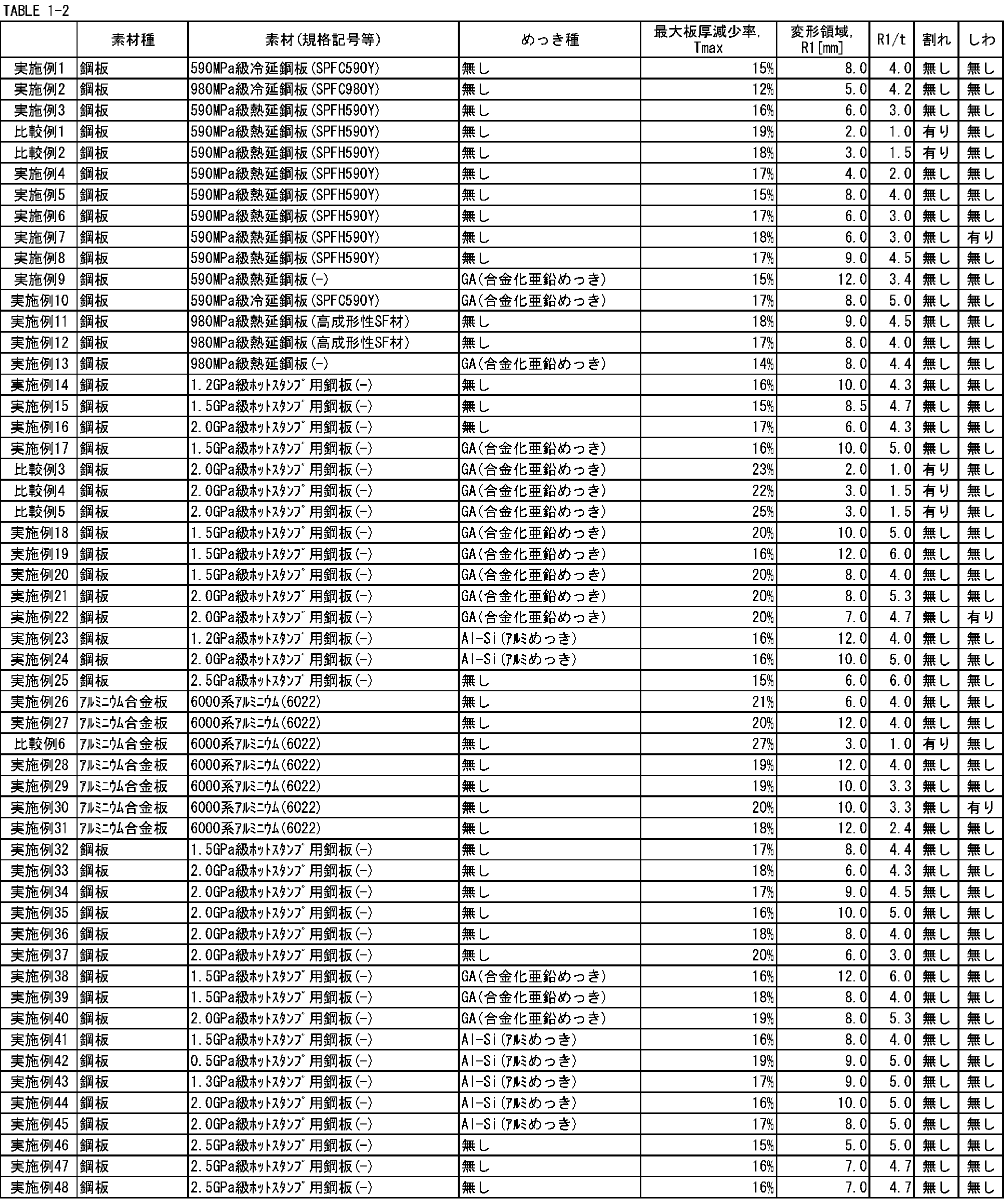
- the step size S (FIG. 3D) between the first lower mold 21 and the second lower mold 22 is 1.0 of the thickness t of the metal plate. more than doubled. Therefore, in each embodiment, after the material is reliably sandwiched between the upper mold 23 and the first lower mold 21, the material is started to be sandwiched between the upper mold 23 and the second lower mold 22, and the second flange 13 was molded. Therefore, in each example, the flow of the material in the second flange 13 was promoted, and cracks in the second flange 13 did not occur.
- the step size S between the first lower mold 21 and the second lower mold 22 is less than 1.0 times the plate thickness t of the material. Therefore, in each comparative example, the clamping of the material between the upper mold 23 and the second lower mold 22 started before the clamping of the material between the upper mold 23 and the first lower mold 21 was completed. Therefore, in each comparative example, it was difficult for the material to flow in the second flange 13 , and cracks occurred in the second flange 13 .
- the second flange 13 will not crack during the molding process. can be prevented from occurring. This effect was confirmed not only in steel sheet forming but also in hot stamping using an aluminum alloy sheet.
- the step size S between the first lower mold 21 and the second lower mold 22 is more than 5.0 times the material thickness t. .
- wrinkles occurred at or near the second flange 13 .
- wrinkles did not occur in other examples in which the step size S was 5.0 times or less the plate thickness t of the material. Therefore, when a step is formed in advance between the first lower mold 21 and the second lower mold 22, if the size S of the step is set to 5.0 times or less of the plate thickness of the material, the second flange 13 and the It is possible to suppress the occurrence of wrinkles in the vicinity thereof.
- cracks in the second flange 13 are likely to occur when the flange portion has no notch and the length of the flange is relatively small, or when the corner R is relatively small.
- the flange length is 0.0 mm or more and 25.0 mm or less, or when the corner R is 20.0 mm or less
- deformation occurs near the R stop of the connection edge 161 at the end edge 132a of the vertical flange portion 132.
- the structural member 10 is manufactured using a steel plate having a tensile strength of 590 MPa or more by a conventional method in which the member body 11, the first flange 12, and the second flange 13 are formed at the same time, the second flange 13 cracks.
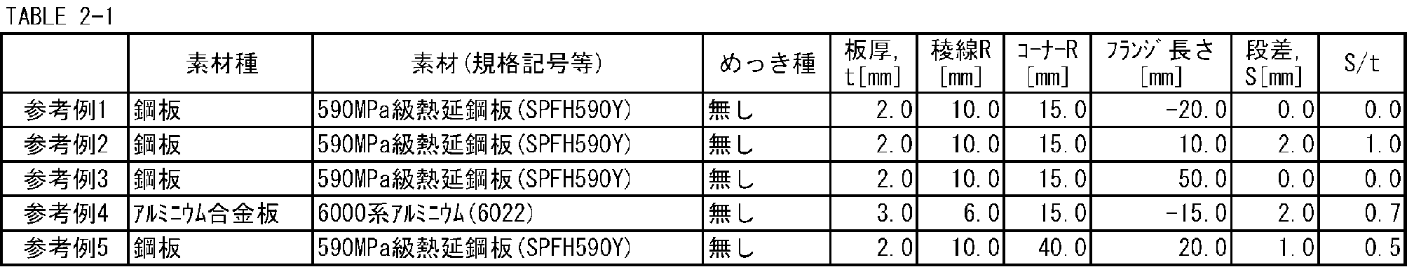
- the conditions of Reference Example 1 are the same as those of Comparative Example 1 except for the flange length.
- the flange length is a positive value and no notch is formed in the flange portion, whereas in Reference Example 1, the flange length is ⁇ 20.0 mm and the flange portion has a notch. is added.
- the conditions of Reference Example 4 are the same as those of Comparative Example 6 except for the flange length.
- the flange length is a positive value and no notch is formed in the flange portion, whereas in Reference Example 4, the flange length is ⁇ 15.0 mm and the flange portion has a notch. is added. Therefore, in Reference Examples 1 and 4, unlike Comparative Examples 1 and 6, cracks did not occur in the second flange 13 .
- Reference Example 5 The conditions of Reference Example 5 are the same as those of Comparative Example 2 except for the corner R.
- the corner R of Reference Example 5 is 40.0 mm, which is significantly larger than the corner R of Comparative Example 2: 15.0 mm. Therefore, in Reference Example 5, unlike Comparative Example 2, cracks did not occur in the second flange 13 .
- the manufacturing method according to the present disclosure suppresses cracking of the second flange 13 . Therefore, in the manufacturing method according to the present disclosure, the structural member 10 in which the second flange 13 is likely to crack, that is, the flange length is 25.0 mm or less, or the curvature radius of the corner portion 141 of the ridge line portion 14 It is suitable for manufacturing the structural member 10 in which the corner R between the vertical flange portion 132 and the vertical wall 112 is 20.0 mm or less.
- the second flange 13 Cracking can be suppressed. Moreover, cracks in the second flange 13 can be suppressed even if the flange length is 25.0 mm or less. Therefore, by increasing the length of the flanges in advance, cracking during molding is suppressed, and there is no need to trim the flanges 12 and 13 after molding. That is, the intermediate trimming process for the flanges 12 and 13 becomes unnecessary.
- FIG. 8 shows the distance from the R stop (vertical flange portion 132 side) of the connection edge 161 connecting the horizontal flange portion 131 and the vertical flange portion 132, and the plate thickness reduction rate T, for the edge 132a of the vertical flange portion 132.
- the deformation region R1 of the edge 132a of the vertical flange portion 132 that is, the length of the region satisfying the above formula (1) long compared to The length of the deformation region R1 in Example 4 was 4.0 mm, which was 2.0 times the plate thickness t of the material: 2.0 mm.
- the length of the deformation region R1 in Example 6 was 6.0 mm, which was 3.0 times the plate thickness t of the material: 2.0 mm.
- the length of the deformation region R1 in Comparative Example 1 was 2.0 mm, which was 1.0 times the plate thickness t of the material: 2.0 mm.
- the length of the deformation region R1 was 2.0 times or more the plate thickness t of the material.
- the length of the deformation region R1 is 6.0 times or less the plate thickness t of the material.
- the length of the deformation region R1 is less than 2.0 times the plate thickness t of the material. From this result, if the structural member 10 is manufactured by the manufacturing method according to the present disclosure, the length of the deformation region R1 is 2.0 times or more the thickness t of the material (thickness t0 of the top plate 111), and 6.0 times. It can be said that the plate thickness distribution of the second flange 13 is made uniform.
- Example 20 When the structural member 10 was molded by hot stamping under the conditions of Example 20, Example 19, and Comparative Example 5, a low-hardness region R2 satisfying the above formula (2) was generated at the edge 132a of the vertical flange portion 132.
- the length of the low hardness region R2 in Example 20 was 10.0 mm, which was 5.0 times the plate thickness t of the material.
- the length of the low-hardness region R2 in Example 19 was 20.0 mm, which was 10.0 times the plate thickness t of the material.
- the length of the low-hardness region R2 in Comparative Example 5 was 8.0 mm, which was 4.0 times the plate thickness t of the material.
- the length of the low-hardness region R2 becomes 5.0 times or more and 10.0 times or less the plate thickness t of the material. It can be said that the hardness distribution of the second flange 13 is made uniform.
Abstract
Description
0.9×Tmax≦T≦Tmax (1)
ただし、Tmax[%]は、縦フランジ部の端縁における板厚減少率の最大値である。
HVTmax-10.0≦HV≦HVTmax+10.0 (2)
ただし、HVTmax[HV]は、縦フランジ部の端縁のうち、板厚減少率の最大値Tmaxを有する部分のビッカース硬さである。HV及びHVTmaxは、試験力294.2Nの場合のビッカース硬さである。
[構造部材の構成]
図1は、第1実施形態に係る構造部材10の斜視図である。構造部材10は、自動車用の構造部材として使用される。構造部材10は、典型的には、自動車の左右方向に延びるフレームである。構造部材10は、例えば、フロアパネル上又はフロアパネル裏に配置されるクロスメンバや、クロスメンバの端部に設けられるクロスエクステンション等である。
以下、構造部材10の製造方法について、図3A~図3Iを参照しつつ説明する。図3A~図3Iは、構造部材10の製造方法を説明するための模式図である。構造部材10の製造方法は、素材Mを準備する工程と、素材Mを構造部材10に成形する工程とを備える。
図3Aを参照して、準備工程では、金属板からなる素材Mを準備する。素材Mは、例えば、構造部材10(図1及び図2)を展開した形状となるように打ち抜き加工されたブランクである。素材Mを構成する金属板は、例えば鋼板である。この鋼板は、例えば、590MPa以上の引張強度を有する。鋼板は、780MPa以上の引張強度を有していてもよいし、980MPa以上の引張強度を有していてもよい。素材Mの板厚は、例えば、1.0mm以上、5.0mm以下である。
図3B~図3Dに示すように、成形工程では、素材Mを構造部材10(図1及び図2)に成形するため、金型20を使用する。まず、金型20の構成について説明する。図3Bは、金型20の斜視図である。図3Cは、金型20の横断面図(IIIC-IIIC断面図)である。図3Dは、金型20の縦断面図(IIID-IIID断面図)である。
図3C及び図3Dに示すように、成形工程を開始する際、プレス機(図示略)のスライドに取り付けられた上型23及びパッド24は、上死点に位置する。この状態で、素材Mを第1下型21の頂面211a上に載置する。その後、プレス機のスライドとともに上型23及びパッド24を下型21,22に向かって下降させ、上型23及びパッド24を下型21,22に対して接近させる。
第1下型21とともに素材Mを挟持した状態の上型23を第2下型22に対してさらに接近させると、上型23により、クッション機構25で支持された第1下型21が押し下げられる。これにより、第1下型21の成形面211と第2下型22の成形面221との段差が徐々に小さくなっていく。図3H及び図3Iを参照して、上型23が下死点に到達したとき、第1下型21と第2下型22との間の段差は消失し、上型23と第2下型22との間で素材Mが挟持(プレス)される。また、パッド24と第2下型22とによって素材Mが挟持される。
0.9×Tmax≦T≦Tmax (1)
本実施形態では、部材本体11及び第1フランジ12を成形するための第1下型21と、第2フランジ13を成形するための第2下型22とを用いて、素材Mから構造部材10を成形する。成形の第1工程では、上型23及びパッド24と第1下型21との間で素材Mが挟持される一方、上型23及びパッド24と第2下型22との間では素材Mが挟持されない。すなわち、成形途中までは、素材Mのうち第2フランジ13となる部分が金型20によって拘束されない。これにより、素材Mのうち第2フランジ13となる部分で材料の流動が生じる。材料は、主に、横フランジ部131側から縦フランジ部132側へと流入する。そのため、各縦フランジ部132の端縁132aや、縦フランジ部132と第1フランジ12との接続部分(コーナー部)において割れが発生するのを抑制することができる。
HVTmax-10.0≦HV≦HVTmax+10.0 (2)
図6は、第2実施形態に係る構造部材10Aの斜視図である。本実施形態に係る構造部材10Aの基本的な構成は、第1実施形態に係る構造部材10と構成と同一である。ただし、構造部材10Aは、部材本体11の天板111の形状において、第1実施形態に係る構造部材10と異なる。


11:部材本体
111:天板
111a:側部
112:縦壁
12:第1フランジ
13:第2フランジ
131:横フランジ部
131a:端部
132:縦フランジ部
132a:端縁
14:稜線部
141:コーナー部
20:金型
21:第1下型
211:成形面
22:第2下型
221:成形面
23:上型
24:パッド
25:クッション機構
M:素材
Claims (12)
- 自動車用の構造部材の製造方法であって、
金属板からなる素材を準備する準備工程と、
金型を用いて前記素材を前記構造部材に成形する成形工程と、
を備え、
前記構造部材は、
前記構造部材の長手方向に延び、且つ前記構造部材の幅方向に対向する2つの側部を有する天板と、前記側部の各々に稜線部を介して接続される縦壁と、を含む部材本体と、
前記天板の反対側で前記縦壁に接続され、前記縦壁から前記幅方向に張り出す第1フランジと、
前記長手方向における前記部材本体の端部に連続して設けられる第2フランジであって、前記天板から前記幅方向に張り出す横フランジ部と、前記横フランジ部の前記部材本体側の端部に前記稜線部を介して接続され、前記横フランジ部から前記第1フランジへと延びる縦フランジ部と、を含む第2フランジと、
を含み、
前記金型は、
上型と、
前記上型に対向して配置され、前記部材本体及び前記第1フランジを成形するための第1下型と、
前記第1下型の隣において前記上型に対向して配置され、前記第2フランジを成形するための第2下型と、
を含み、
前記成形工程は、
前記上型と前記第1下型とで前記素材を挟持する一方、前記上型と前記第2下型とで前記素材を挟持しない第1工程と、
前記第1工程の後、前記上型と前記第2下型とで前記素材を挟持して前記第2フランジを成形する第2工程と、
を含む、製造方法。 - 請求項1に記載の製造方法であって、
前記金型は、さらに、パッドを含み、
前記第1工程では、前記パッドで前記素材を押さえた後で、前記上型と前記第1下型とで前記素材を挟持する、製造方法。 - 請求項1又は2に記載の製造方法であって、
前記第1下型の成形面と前記第2下型の成形面との間に予め段差を生じさせておくことにより、前記第1工程において、前記上型を前記第1下型及び前記第2下型に対して相対的に接近させたときに、前記第1下型が前記第2下型に先行して前記上型との間で前記素材を挟持し、
前記第2工程では、前記第1下型とともに前記素材を挟持した状態の前記上型を前記第2下型に対してさらに接近させることにより、前記段差が消失して前記第2下型が前記上型との間で前記素材を挟持し、
前記第1工程の開始前における前記段差の大きさは、前記素材の板厚以上、前記板厚の5.0倍以下である、製造方法。 - 請求項3に記載の製造方法であって、
前記第1下型は、クッション機構によって昇降可能に構成されており、
前記成形工程では、前記上型を前記第1下型及び前記第2下型に向かって下降させる、製造方法。 - 請求項1に記載の製造方法であって、さらに、
金属板から中間成形品を成形する予備成形工程を備え、
前記成形工程では、前記中間成形品を前記素材として、当該素材から前記構造部材を成形する、製造方法。 - 請求項1に記載の製造方法であって、さらに、
前記素材を加熱する加熱工程を備え、
前記成形工程では、前記加熱工程で加熱された前記素材を前記構造部材に成形する、製造方法。 - 請求項1に記載の製造方法であって、
前記金属板は、590MPa以上の引張強度を有する鋼板である、製造方法。 - 自動車用の構造部材であって、
前記構造部材の長手方向に延び、且つ前記構造部材の幅方向に対向する2つの側部を有する天板と、前記側部の各々に稜線部を介して接続される縦壁と、を含む部材本体と、
前記天板の反対側で前記縦壁に接続され、前記縦壁から前記幅方向に張り出す第1フランジと、
前記長手方向における前記部材本体の端部に連続して設けられる第2フランジであって、前記天板から前記幅方向に張り出す横フランジ部と、前記横フランジ部の前記部材本体側の端部に前記稜線部を介して接続され、前記横フランジ部から前記第1フランジへと延びる縦フランジ部と、を含む第2フランジと、
を備え、
前記天板の板厚を基準とする板厚減少率をT[%]としたとき、前記縦フランジ部の端縁において以下の式(1)を満たす板厚減少率Tを有する領域の長さは、前記板厚の2.0倍以上、6.0倍以下である、構造部材。
0.9×Tmax≦T≦Tmax (1)
ただし、Tmax[%]は、前記縦フランジ部の前記端縁における前記板厚減少率の最大値である。 - 請求項8に記載の構造部材であって、
前記縦フランジ部の前記端縁において以下の式(2)を満たすビッカース硬さHV[HV]を有する領域の長さは、前記板厚の5.0倍以上、10.0倍以下である、構造部材。
HVTmax-10.0≦HV≦HVTmax+10.0 (2)
ただし、HVTmax[HV]は、前記縦フランジ部の前記端縁のうち、前記板厚減少率の最大値Tmaxを有する部分のビッカース硬さである。 - 請求項8に記載の構造部材であって、
前記縦フランジ部の表面において互いに前記板厚以上離れている30箇所で測定されるビッカース硬さの平均値は300.0Hv以上であり、当該ビッカース硬さの標準偏差は70.0Hv以下である、構造部材。 - 請求項8に記載の構造部材であって、
当該構造部材は、590MPa以上の引張強度を有する鋼板で形成されている、構造部材。 - 請求項8から11のいずれか1項に記載の構造部材であって、
前記稜線部は、前記天板から前記横フランジ部に向かって延在し、前記構造部材の平面視で20.0mm以下の曲率半径を有するコーナー部を含む、構造部材。
Priority Applications (2)
| Application Number | Priority Date | Filing Date | Title |
|---|---|---|---|
| CN202280053178.5A CN117751020A (zh) | 2021-09-03 | 2022-08-30 | 构造构件及其制造方法 |
| JP2023512036A JP7311830B1 (ja) | 2021-09-03 | 2022-08-30 | 構造部材及びその製造方法 |
Applications Claiming Priority (2)
| Application Number | Priority Date | Filing Date | Title |
|---|---|---|---|
| JP2021143894 | 2021-09-03 | ||
| JP2021-143894 | 2021-09-03 |
Publications (1)
| Publication Number | Publication Date |
|---|---|
| WO2023032953A1 true WO2023032953A1 (ja) | 2023-03-09 |
Family
ID=85411223
Family Applications (1)
| Application Number | Title | Priority Date | Filing Date |
|---|---|---|---|
| PCT/JP2022/032517 WO2023032953A1 (ja) | 2021-09-03 | 2022-08-30 | 構造部材及びその製造方法 |
Country Status (3)
| Country | Link |
|---|---|
| JP (1) | JP7311830B1 (ja) |
| CN (1) | CN117751020A (ja) |
| WO (1) | WO2023032953A1 (ja) |
Citations (7)
| Publication number | Priority date | Publication date | Assignee | Title |
|---|---|---|---|---|
| JP2013035068A (ja) * | 2010-05-19 | 2013-02-21 | Nippon Steel & Sumitomo Metal Corp | L字状形状を有する部品のプレス成形方法 |
| CN105478596A (zh) * | 2016-02-02 | 2016-04-13 | 奇瑞汽车股份有限公司 | 一种复杂型面多行程拉延模具结构 |
| JP5958644B2 (ja) | 2013-03-21 | 2016-08-02 | 新日鐵住金株式会社 | プレス成形部材の製造方法及びプレス成形装置 |
| JP2016175089A (ja) * | 2015-03-18 | 2016-10-06 | 新日鐵住金株式会社 | 熱間プレス用金型、熱間プレス装置および熱間プレス成形品の製造方法 |
| JP6436166B2 (ja) | 2014-05-14 | 2018-12-12 | 新日鐵住金株式会社 | ブランク及びプレス成形品の製造方法 |
| JP2019013952A (ja) | 2017-07-06 | 2019-01-31 | Jfeスチール株式会社 | プレス成形方法 |
| JP2020152173A (ja) * | 2019-03-19 | 2020-09-24 | Jfeスチール株式会社 | 車体骨格部品の継手構造、車体骨格部品及び該車体骨格部品の製造方法 |
-
2022
- 2022-08-30 WO PCT/JP2022/032517 patent/WO2023032953A1/ja active Application Filing
- 2022-08-30 JP JP2023512036A patent/JP7311830B1/ja active Active
- 2022-08-30 CN CN202280053178.5A patent/CN117751020A/zh active Pending
Patent Citations (7)
| Publication number | Priority date | Publication date | Assignee | Title |
|---|---|---|---|---|
| JP2013035068A (ja) * | 2010-05-19 | 2013-02-21 | Nippon Steel & Sumitomo Metal Corp | L字状形状を有する部品のプレス成形方法 |
| JP5958644B2 (ja) | 2013-03-21 | 2016-08-02 | 新日鐵住金株式会社 | プレス成形部材の製造方法及びプレス成形装置 |
| JP6436166B2 (ja) | 2014-05-14 | 2018-12-12 | 新日鐵住金株式会社 | ブランク及びプレス成形品の製造方法 |
| JP2016175089A (ja) * | 2015-03-18 | 2016-10-06 | 新日鐵住金株式会社 | 熱間プレス用金型、熱間プレス装置および熱間プレス成形品の製造方法 |
| CN105478596A (zh) * | 2016-02-02 | 2016-04-13 | 奇瑞汽车股份有限公司 | 一种复杂型面多行程拉延模具结构 |
| JP2019013952A (ja) | 2017-07-06 | 2019-01-31 | Jfeスチール株式会社 | プレス成形方法 |
| JP2020152173A (ja) * | 2019-03-19 | 2020-09-24 | Jfeスチール株式会社 | 車体骨格部品の継手構造、車体骨格部品及び該車体骨格部品の製造方法 |
Also Published As
| Publication number | Publication date |
|---|---|
| CN117751020A (zh) | 2024-03-22 |
| JP7311830B1 (ja) | 2023-07-20 |
| JPWO2023032953A1 (ja) | 2023-03-09 |
Similar Documents
| Publication | Publication Date | Title |
|---|---|---|
| KR101701082B1 (ko) | 프레스 부품의 제조 방법 및 제조 장치 | |
| TWI555593B (zh) | 毛坯、成形板、及壓製成形品之製造方法 | |
| CN109414745B (zh) | 冲压部件的制造方法及制造装置 | |
| EP2896467B1 (en) | Method for producing curved article | |
| TWI448338B (zh) | 具有l字狀形狀之零件的壓製成形方法 | |
| KR101305927B1 (ko) | 폐구조 부재의 제조 방법, 프레스 성형 장치 및 폐구조 부재 | |
| KR101863469B1 (ko) | 강판 소재, 그 제조 방법 및 제조 장치, 및 그 강판 소재를 이용한 프레스 성형품의 제조 방법 | |
| JP5378738B2 (ja) | 閉構造部材の製造方法、プレス成形装置 | |
| US11020785B2 (en) | Method and apparatus for manufacturing press component | |
| KR20160145130A (ko) | 블랭크 및 프레스 성형품의 제조 방법 | |
| JP7311830B1 (ja) | 構造部材及びその製造方法 | |
| WO2017141603A1 (ja) | プレス成形品の製造方法 | |
| KR102450454B1 (ko) | 프레스 성형 방법 | |
| JP7273355B1 (ja) | 構造部材及びその製造方法 | |
| JP6733773B1 (ja) | プレス成形方法 |
Legal Events
| Date | Code | Title | Description |
|---|---|---|---|
| ENP | Entry into the national phase |
Ref document number: 2023512036 Country of ref document: JP Kind code of ref document: A |
|
| 121 | Ep: the epo has been informed by wipo that ep was designated in this application |
Ref document number: 22864535 Country of ref document: EP Kind code of ref document: A1 |
|
| WWE | Wipo information: entry into national phase |
Ref document number: 2022864535 Country of ref document: EP |
|
| ENP | Entry into the national phase |
Ref document number: 2022864535 Country of ref document: EP Effective date: 20240403 |