WO2025079665A1 - 蓄電デバイス及びその製造方法 - Google Patents
蓄電デバイス及びその製造方法 Download PDFInfo
- Publication number
- WO2025079665A1 WO2025079665A1 PCT/JP2024/036368 JP2024036368W WO2025079665A1 WO 2025079665 A1 WO2025079665 A1 WO 2025079665A1 JP 2024036368 W JP2024036368 W JP 2024036368W WO 2025079665 A1 WO2025079665 A1 WO 2025079665A1
- Authority
- WO
- WIPO (PCT)
- Prior art keywords
- active material
- layer
- electrolyte
- storage device
- negative electrode
- Prior art date
- Legal status (The legal status is an assumption and is not a legal conclusion. Google has not performed a legal analysis and makes no representation as to the accuracy of the status listed.)
- Pending
Links
Images

Classifications
-
- H—ELECTRICITY
- H01—ELECTRIC ELEMENTS
- H01M—PROCESSES OR MEANS, e.g. BATTERIES, FOR THE DIRECT CONVERSION OF CHEMICAL ENERGY INTO ELECTRICAL ENERGY
- H01M10/00—Secondary cells; Manufacture thereof
- H01M10/05—Accumulators with non-aqueous electrolyte
- H01M10/052—Li-accumulators
-
- H—ELECTRICITY
- H01—ELECTRIC ELEMENTS
- H01M—PROCESSES OR MEANS, e.g. BATTERIES, FOR THE DIRECT CONVERSION OF CHEMICAL ENERGY INTO ELECTRICAL ENERGY
- H01M10/00—Secondary cells; Manufacture thereof
- H01M10/05—Accumulators with non-aqueous electrolyte
- H01M10/056—Accumulators with non-aqueous electrolyte characterised by the materials used as electrolytes, e.g. mixed inorganic/organic electrolytes
- H01M10/0561—Accumulators with non-aqueous electrolyte characterised by the materials used as electrolytes, e.g. mixed inorganic/organic electrolytes the electrolyte being constituted of inorganic materials only
- H01M10/0562—Solid materials
-
- H—ELECTRICITY
- H01—ELECTRIC ELEMENTS
- H01M—PROCESSES OR MEANS, e.g. BATTERIES, FOR THE DIRECT CONVERSION OF CHEMICAL ENERGY INTO ELECTRICAL ENERGY
- H01M10/00—Secondary cells; Manufacture thereof
- H01M10/05—Accumulators with non-aqueous electrolyte
- H01M10/056—Accumulators with non-aqueous electrolyte characterised by the materials used as electrolytes, e.g. mixed inorganic/organic electrolytes
- H01M10/0564—Accumulators with non-aqueous electrolyte characterised by the materials used as electrolytes, e.g. mixed inorganic/organic electrolytes the electrolyte being constituted of organic materials only
- H01M10/0565—Polymeric materials, e.g. gel-type or solid-type
-
- H—ELECTRICITY
- H01—ELECTRIC ELEMENTS
- H01M—PROCESSES OR MEANS, e.g. BATTERIES, FOR THE DIRECT CONVERSION OF CHEMICAL ENERGY INTO ELECTRICAL ENERGY
- H01M10/00—Secondary cells; Manufacture thereof
- H01M10/05—Accumulators with non-aqueous electrolyte
- H01M10/058—Construction or manufacture
- H01M10/0585—Construction or manufacture of accumulators having only flat construction elements, i.e. flat positive electrodes, flat negative electrodes and flat separators
-
- H—ELECTRICITY
- H01—ELECTRIC ELEMENTS
- H01M—PROCESSES OR MEANS, e.g. BATTERIES, FOR THE DIRECT CONVERSION OF CHEMICAL ENERGY INTO ELECTRICAL ENERGY
- H01M4/00—Electrodes
- H01M4/02—Electrodes composed of, or comprising, active material
- H01M4/13—Electrodes for accumulators with non-aqueous electrolyte, e.g. for lithium-accumulators; Processes of manufacture thereof
-
- Y—GENERAL TAGGING OF NEW TECHNOLOGICAL DEVELOPMENTS; GENERAL TAGGING OF CROSS-SECTIONAL TECHNOLOGIES SPANNING OVER SEVERAL SECTIONS OF THE IPC; TECHNICAL SUBJECTS COVERED BY FORMER USPC CROSS-REFERENCE ART COLLECTIONS [XRACs] AND DIGESTS
- Y02—TECHNOLOGIES OR APPLICATIONS FOR MITIGATION OR ADAPTATION AGAINST CLIMATE CHANGE
- Y02E—REDUCTION OF GREENHOUSE GAS [GHG] EMISSIONS, RELATED TO ENERGY GENERATION, TRANSMISSION OR DISTRIBUTION
- Y02E60/00—Enabling technologies; Technologies with a potential or indirect contribution to GHG emissions mitigation
- Y02E60/10—Energy storage using batteries
Definitions
- the sixth aspect is a method for manufacturing an electricity storage device that utilizes ionic conduction and includes a positive electrode, a negative electrode, and a separator that separates the positive electrode and the negative electrode, in which the negative electrode includes an active material layer that includes an active material that causes an oxidation-reduction reaction, an electrolyte layer that includes a solid electrolyte and an electrolyte solution that are conductive to carrier ions and that is in contact with the active material layer, and a conductive layer that is electronically conductive and in contact with the electrolyte layer and captures carrier ions, and includes a step of stacking the positive electrode, separator, and negative electrode in that order, and a step of passing a current from the negative electrode to the positive electrode to precipitate elements contained in the electrolyte layer at the interface between the active material layer and the electrolyte layer.
- an electric storage device of the present invention when a current is passed from the negative electrode to the positive electrode, elements contained in the electrolyte layer are precipitated at the interface between the electrolyte layer and the active material layer. When dendrites grow in the electrolyte layer toward the positive electrode, elements are also precipitated at the interface of the electrolyte layer that has become electronically conductive due to the dendrites.
- the power storage device of the present invention has a conductive layer and an electrolyte layer, the reaction of elements precipitating during charging occurs almost uniformly over the entire interface of the conductive layer, compared to the reaction at the interface of the negative electrode when the power storage device does not have a conductive layer or electrolyte layer. Elements also precipitate inside the conductive layer, but the precipitated elements are incorporated into the conductive layer, improving the element loading rate in the conductive layer, and thus dendrite growth can be reduced. Since there is no need to pressurize the cell while charging and discharging in order to reduce dendrite growth, dendrite growth can be reduced while suppressing any increase in the mass and volume of the power storage device.
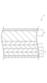
- Fig. 1 is a schematic cross-sectional view of an electricity storage device 10 according to one embodiment.
- the electricity storage device 10 uses ions as carriers.
- ions that serve as carriers include metal ions such as Li + , Na + , K + , Mg 2+ , Cu + , and Ag + , and anions such as OH - , F - , and H - , but there is no limitation on the type of ions.
- Examples of the electricity storage device 10 include an ion battery such as a lithium ion battery that uses ions such as Li + , Na + , K + , Mg 2+ , F - , and H - as carriers, an electrochemical capacitor that uses a redox reaction of an electrode or an ion in an electrolyte, or an electric double layer, and a metal-air battery that uses oxygen in the air as the positive electrode active material and a metal such as Li, Zn, Al, Mg, or Fe as the negative electrode active material.
- the electricity storage device 10 includes, in order, a positive electrode 11, a separator 14, and a negative electrode 15.
- the negative electrode 15 includes, in order toward the positive electrode 11, an active material layer 17, an electrolyte layer 18, and a conductive layer 19.
- a conductive current collector 16 can be disposed on the active material layer 17. Examples of materials for the current collector 16 include metals selected from Ni, Ti, Fe, Cu, and Si, alloys containing two or more of these elements, stainless steel, and carbon materials.
- the active material layer 17 contains an active material (negative electrode active material). There are no restrictions on the material of the active material as long as it can absorb and release carrier ions. The active material is selected appropriately depending on the type of carrier ion.
- the active material layer 17 can be, for example, an aggregate of particles made of these materials, a plate made of these materials, or a porous body carrying these materials. Of these, metallic lithium and alloy-based active materials, which have a higher capacity density than carbon-based active materials, are preferred.
- the active material layer 17 may contain a conductive additive to reduce the resistance of the active material layer 17. Examples of conductive additives include carbon black, acetylene black, ketjen black, carbon fiber, Ni, Pt, and Ag.
- the Li present in the void V is octahedrally coordinated with the oxygen atom Oa that constitutes an octahedron including the tetrahedral surface Fb1 that forms the B site Sb1 and the tetrahedral surface Fb2 that forms the B site Sb2.
- the oxygen atom Oa that constitutes an octahedron including the tetrahedral surface Fb1 that forms the B site Sb1 and the tetrahedral surface Fb2 that forms the B site Sb2.
- La may occupy the C site Sc
- Zr may occupy the A site Sa
- Li may occupy the B site Sb and the voids V.
- the garnet-type crystal structure can be identified by X-ray diffraction.
- the garnet-type crystal structure has an XRD pattern similar to that of X-ray diffraction file No. 422259 (Li 7 La 3 Zr 2 O 12 ) in the Cambridge Structural Database (CSD).
- the solid electrolyte may differ from No. 422259 in terms of the type of constituent elements, Li concentration, etc., and therefore the diffraction angle and intensity ratio may differ.
- a typical crystal structure of this type is a cubic system (space group Ia-3d (- indicates an overline that means a reversal operation), JCPDS: 84-1753).
- a typical example of a solid electrolyte having a garnet-type crystal structure is Li 7 La 3 Zr 2 O 12.
- the solid electrolyte may have a part of the constituent elements of Li 7 La 3 Zr 2 O 12 replaced with other elements, or may have a small amount of other elements added without replacing the constituent elements.
- the other elements include at least one element selected from the group consisting of Mg, Al, Si, Ca, Ti, V, Ga, Sr, Y, Nb, Sn, Sb, Ba, Hf, Ta, W, Bi, Rb, and lanthanoids (excluding La).
- Examples of solid electrolytes include Li 6 La 3 Zr 1.5 W 0.5 O 12 , Li 6.15 La 3 Zr 1.75 Ta 0.25 Al 0.2 O 12 , Li 6.15 La 3 Zr 1.75 Ta 0.25 Ga 0.2 O 12 , Li 6.25 La 3 Zr 2 Ga 0.25 O 12 , Li 6.4 La 3 Zr 1.4 Ta 0.6 O 12 , Li 6.5 La 3 Zr 1.75 Te 0.25 O 12 , Li 6.75 La 3 Zr 1.75 Nb 0.25 O 12 , Li 6.9 La 3 Zr 1.675 Ta 0.289 Bi 0.036 O 12 , Li 6.46 Ga 0.23 La 3 Zr 1.85 Y 0.15 O 12 , Li 6.8 La 2.95 Ca
- Examples include 0.05 Zr 1.75 Nb 0.25 O 12 , Li 7.05 La 3.00 Zr 1.95 Gd 0.05 O 12 , Li 6.20 Ba 0.30 La 2.95 Rb 0.05 Zr 2 O 12 .
- the solid electrolyte preferably contains at least one of Mg and element A (A is at least one element selected from the group consisting of Ca, Sr, and Ba) and the molar ratio of each element satisfies all of the following (1) to (3), or contains both Mg and element A and the molar ratio of each element satisfies all of the following (4) to (6).
- Element A is preferably Sr in order to increase the ionic conductivity of the solid electrolyte. This is because when some of the constituent elements of Li 7 La 3 Zr 2 O 12 are replaced with Mg and Sr, the ionic conductivity of the solid electrolyte increases and metallic lithium precipitates more densely.
- the electrolyte solution contained in the electrolyte layer 18 is a medium in which carrier ions move, and is a solution in which a metal salt is dissolved in a solvent.
- a solvent there are no particular limitations on the solvent, so long as it dissolves the metal salt.
- Aqueous and non-aqueous solvents can be used without limitation. Examples of non-aqueous solvents include carbonate esters, aliphatic carboxylate esters, phosphate esters, ⁇ -lactones, ethers, nitriles, sulfolane, dimethyl sulfoxide, fluorous solvents, and ionic liquids. Mixtures of these may also be used.
- carbonate esters examples include cyclic carbonate esters such as propylene carbonate, ethylene carbonate, butylene carbonate, vinylene carbonate, vinylethylene carbonate, and fluoroethylene carbonate, and chain carbonate esters such as dimethyl carbonate, diethyl carbonate, and ethyl methyl carbonate.
- Ionic liquids are compounds consisting of cations and anions, and are liquid at room temperature and pressure. If the solvent of an electrolyte is an ionic liquid, the flame retardancy of the electrolyte can be improved. Ionic liquids are preferred because they have a relatively wide potential window. Ionic liquids that contain one or more cationic species selected from the group consisting of ammonium, imidazolium, pyrrolidinium, and piperidinium are preferred.
- the ionic liquids are N,N-diethyl-N-methyl-N-(2-methoxyethyl)ammonium bis(fluorosulfonyl)imide (DEME-FSI), N,N-diethyl-N-methyl-N-(2-methoxyethyl)ammonium bis(trifluoromethanesulfonyl)imide (DEME-TFSI), 1-ethyl-3-methylimidazolium bis(fluorosulfonyl)imide (EMI-FSI), 1-ethyl-3-methylimidazolium bis(trifluoromethanesulfonyl)imide (EMI-FSI), Examples include N-butyl-N-methylpiperidinium bis(fluorosulfonyl)imide (EMI-TFSI), N-butyl-N-methylpiperidinium bis(fluorosulfonyl)imide, N-methyl-N-propylpiperidinium bis(tri
- the ionic liquid may be a solvated ionic liquid.
- solvated ionic liquids include sulfone-based solvents such as sulfolane and sulfolane derivatives, or glyme-based solvents such as tetraglyme in which a metal salt is dissolved.
- the anions of the metal salts are OH - , halide ions (I - , Cl - , Br - , etc.), SCN - , BF 4 - , BF 3 (CF 3 ) - , BF 3 (C 2 F 5 ) - , PF 6 - , ClO 4 - , SbF 6 - , N(SO 2 F) 2 - , N(SO 2 CF 3 ) 2 - , N(SO 2 C 2 F 5 ) 2 - , B(C 6 H 5 ) 4 - , B(O 2 C 2 H 4 ) 2 - , C(SO 2 F) 3 - , C(SO 2 CF 3 ) 3 - , CF 3 COO - , CF Examples include 3SO2O- , C6F5SO2O-, B ( O2C2O2 ) 2- , RCOO- ( wherein R is an alkyl group having 1 to 4 carbon
- the vinylidene fluoride polymer is not particularly limited as long as it contains -CH 2 CF 2 -.
- the vinylidene fluoride polymer include a homopolymer of vinylidene fluoride and a copolymer of vinylidene fluoride and a copolymerizable monomer.
- the copolymerizable monomer include a halogen-containing monomer (excluding vinylidene fluoride) and a non-halogen copolymerizable monomer.
- the binder and the electrolyte may be present separately in the electrolyte layer 18, or the binder and the electrolyte may be mixed together to form a gel.
- the electrolyte layer 18 may contain a solvent that dissolves the binder. It is preferable that the binder has a wider potential window than the electrolyte.
- the electrolyte layer 18 may contain a polymer for the purpose of improving the electrochemical stability of the electrolyte layer 18.
- polymer materials include polyethylene, polypropylene, polyethylene terephthalate, polystyrene, polyamide, polyvinyl alcohol, ethylene-vinyl alcohol copolymer, polyvinylidene chloride, polyacrylonitrile, polycarbonate, and silicone.
- the polymer may be in various shapes such as grains, fibers, and scales.
- the material of the metal layer is selected appropriately according to the type of carrier ion and is not corroded by the electrolyte.
- the metal layer include an aggregate of particles containing the alloying metal, a plate or mesh made of a material containing the alloying metal, a porous body carrying the alloying metal, and a porous body made of the alloying metal.
- alloys include complete solid solution alloys, eutectic alloys, hypoeutectic alloys, hypereutectic alloys, and peritectic alloys.
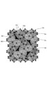
- FIG. 3 is a schematic diagram of the conductive layer 19.
- the conductive layer 19 includes a capture body 20 that has electronic conductivity and adsorbs molecules, for example.
- the molecules include elements produced by the reaction of carrier ions.
- the molecules may include one or more elements that constitute the electrolyte layer 19.
- Any capture body 20 that has a molecular adsorption site can be used without restrictions.
- the adsorption mechanism of the capture body 20 may be either chemical adsorption or physical adsorption.
- charging is performed at a constant current of 0.2C until the terminal voltage reaches the upper charging voltage (e.g. 4.3V), and then constant voltage charging is performed until the current value is 0.01C.
- Discharging in the first and second cycles is performed at a constant current of 0.2C until the terminal voltage reaches 3.0V, and then constant voltage discharging is performed until the current value is 0.01C.
- Discharging in the third cycle is performed at a constant current of 0.5C until the terminal voltage reaches 3.0V, and then constant voltage discharging is performed until the current value is 0.01C.
- the reaction at the interface between the conductive layer 19 and separator 14 occurs almost uniformly across the entire interface between the conductive layer 19 and separator 14, compared to the reaction at the interface between the active material layer 17 and separator 14 when the electrolyte layer 18 and conductive layer 19 are not present.
- a phase with a structure different from that of the electrolyte layer 18 is formed at the interface between the conductive layer 19 and separator 14 due to the reduction of the compounds contained in the electrolyte layer 18, and this phase is incorporated into the conductive layer 19.
Landscapes
- Chemical & Material Sciences (AREA)
- Engineering & Computer Science (AREA)
- Chemical Kinetics & Catalysis (AREA)
- Electrochemistry (AREA)
- General Chemical & Material Sciences (AREA)
- Manufacturing & Machinery (AREA)
- Physics & Mathematics (AREA)
- Condensed Matter Physics & Semiconductors (AREA)
- General Physics & Mathematics (AREA)
- Inorganic Chemistry (AREA)
- Materials Engineering (AREA)
- Dispersion Chemistry (AREA)
- Secondary Cells (AREA)
Priority Applications (2)
| Application Number | Priority Date | Filing Date | Title |
|---|---|---|---|
| JP2025528387A JP7815551B2 (ja) | 2023-10-11 | 2024-10-11 | 蓄電デバイス及びその製造方法 |
| CN202480063960.4A CN121970169A (zh) | 2023-10-11 | 2024-10-11 | 蓄电器件及其制造方法 |
Applications Claiming Priority (2)
| Application Number | Priority Date | Filing Date | Title |
|---|---|---|---|
| JP2023175783 | 2023-10-11 | ||
| JP2023-175783 | 2023-10-11 |
Publications (1)
| Publication Number | Publication Date |
|---|---|
| WO2025079665A1 true WO2025079665A1 (ja) | 2025-04-17 |
Family
ID=95395872
Family Applications (1)
| Application Number | Title | Priority Date | Filing Date |
|---|---|---|---|
| PCT/JP2024/036368 Pending WO2025079665A1 (ja) | 2023-10-11 | 2024-10-11 | 蓄電デバイス及びその製造方法 |
Country Status (3)
| Country | Link |
|---|---|
| JP (1) | JP7815551B2 (https=) |
| CN (1) | CN121970169A (https=) |
| WO (1) | WO2025079665A1 (https=) |
Citations (6)
| Publication number | Priority date | Publication date | Assignee | Title |
|---|---|---|---|---|
| JP2014238925A (ja) * | 2013-06-06 | 2014-12-18 | 日本碍子株式会社 | 全固体電池 |
| JP2018110098A (ja) * | 2016-12-28 | 2018-07-12 | パナソニックIpマネジメント株式会社 | 電池 |
| KR20190079321A (ko) * | 2017-12-27 | 2019-07-05 | 삼성전자주식회사 | 음극, 이를 포함하는 리튬전지 및 음극 제조방법 |
| WO2020196040A1 (ja) * | 2019-03-22 | 2020-10-01 | 富士フイルム株式会社 | 全固体リチウムイオン二次電池とその製造方法、及び負極用積層シート |
| CN112490496A (zh) * | 2020-12-05 | 2021-03-12 | 浙江锋锂新能源科技有限公司 | 一种复合固体电解质及其制备方法和锂蓄电池 |
| WO2022038670A1 (ja) * | 2020-08-18 | 2022-02-24 | TeraWatt Technology株式会社 | リチウム2次電池 |
Family Cites Families (1)
| Publication number | Priority date | Publication date | Assignee | Title |
|---|---|---|---|---|
| JP7143704B2 (ja) * | 2018-09-25 | 2022-09-29 | トヨタ自動車株式会社 | リチウム二次電池 |
-
2024
- 2024-10-11 JP JP2025528387A patent/JP7815551B2/ja active Active
- 2024-10-11 CN CN202480063960.4A patent/CN121970169A/zh active Pending
- 2024-10-11 WO PCT/JP2024/036368 patent/WO2025079665A1/ja active Pending
Patent Citations (6)
| Publication number | Priority date | Publication date | Assignee | Title |
|---|---|---|---|---|
| JP2014238925A (ja) * | 2013-06-06 | 2014-12-18 | 日本碍子株式会社 | 全固体電池 |
| JP2018110098A (ja) * | 2016-12-28 | 2018-07-12 | パナソニックIpマネジメント株式会社 | 電池 |
| KR20190079321A (ko) * | 2017-12-27 | 2019-07-05 | 삼성전자주식회사 | 음극, 이를 포함하는 리튬전지 및 음극 제조방법 |
| WO2020196040A1 (ja) * | 2019-03-22 | 2020-10-01 | 富士フイルム株式会社 | 全固体リチウムイオン二次電池とその製造方法、及び負極用積層シート |
| WO2022038670A1 (ja) * | 2020-08-18 | 2022-02-24 | TeraWatt Technology株式会社 | リチウム2次電池 |
| CN112490496A (zh) * | 2020-12-05 | 2021-03-12 | 浙江锋锂新能源科技有限公司 | 一种复合固体电解质及其制备方法和锂蓄电池 |
Non-Patent Citations (1)
| Title |
|---|
| SHOICHI MATSUDA: "Effect of Confining Pressure on the Repeated Lithium Deposition/Dissolution Reaction", PROCEEDINGS OF THE 62ND BATTERY SYMPOSIUM IN JAPAN, THE BATTERY TECHNOLOGY COMMITTEE OF THE ELECTROCHEMICAL SOCIETY OF JAPAN, 30 November 2021 (2021-11-30) |
Also Published As
| Publication number | Publication date |
|---|---|
| JP7815551B2 (ja) | 2026-02-17 |
| JPWO2025079665A1 (https=) | 2025-04-17 |
| CN121970169A (zh) | 2026-05-01 |
Similar Documents
| Publication | Publication Date | Title |
|---|---|---|
| US6884547B2 (en) | Lithium polymer battery | |
| CN108701860A (zh) | 固体电解质材料和电池 | |
| US20230344000A1 (en) | Fabrication process for polymer-based bipolar batteries via in-situ polymerization | |
| WO2012056765A1 (ja) | 二次電池及びその製造方法 | |
| CN111816923B (zh) | 锂二次电池及其制造方法 | |
| CN1794511A (zh) | 电池 | |
| KR20170042281A (ko) | 나트륨 이온 2차 전지용 양극 및 나트륨 이온 2차 전지 | |
| KR20120089197A (ko) | 전기화학 장치용 전해액 및 전기화학 장치 | |
| US20250260059A1 (en) | Electrolyte for secondary battery, secondary battery, battery module, battery pack, and electric apparatus | |
| CN115693029A (zh) | 制备用于电化学电池的功能粒子的方法和包括所述功能粒子的电化学电池 | |
| JP5169181B2 (ja) | 非水電解液二次電池 | |
| JP7822895B2 (ja) | 非水電解質二次電池用正極および非水電解質二次電池 | |
| CN115621663A (zh) | 用于电化学电池的锂离子交换沸石粒子及其制造方法 | |
| US20240162478A1 (en) | Lithium secondary battery | |
| KR20230137979A (ko) | 충전식 배터리 셀 | |
| WO2025010817A1 (zh) | 电解液、二次电池和用电装置 | |
| CN1860639A (zh) | 含有用于提高锂离子电池容量的添加剂的非水系电解液和使用其的锂离子电池 | |
| KR20240061891A (ko) | 리튬 이차 전지 | |
| JP6065847B2 (ja) | リチウム二次電池及びリチウム二次電池用電解液 | |
| JP6123674B2 (ja) | リチウム二次電池及びこれを用いた車両 | |
| JP3327468B2 (ja) | リチウムイオン二次電池及びその製造方法 | |
| JP2024125456A (ja) | 二次電池およびその製造方法 | |
| EP4654287A1 (en) | Negative electrode for lithium secondary battery and lithium secondary battery comprising same | |
| JP7815551B2 (ja) | 蓄電デバイス及びその製造方法 | |
| KR100424440B1 (ko) | 리튬이차전지용 바인더 조성물 및 그 응용 |
Legal Events
| Date | Code | Title | Description |
|---|---|---|---|
| ENP | Entry into the national phase |
Ref document number: 2025528387 Country of ref document: JP Kind code of ref document: A |
|
| WWE | Wipo information: entry into national phase |
Ref document number: 2025528387 Country of ref document: JP |
|
| 121 | Ep: the epo has been informed by wipo that ep was designated in this application |
Ref document number: 24877259 Country of ref document: EP Kind code of ref document: A1 |