WO2025074956A1 - セラミックス成形体の充填方法、cip体の製造方法、セラミックス焼結体の製造方法、及び、セラミックスボール用素材の製造方法 - Google Patents
セラミックス成形体の充填方法、cip体の製造方法、セラミックス焼結体の製造方法、及び、セラミックスボール用素材の製造方法 Download PDFInfo
- Publication number
- WO2025074956A1 WO2025074956A1 PCT/JP2024/034767 JP2024034767W WO2025074956A1 WO 2025074956 A1 WO2025074956 A1 WO 2025074956A1 JP 2024034767 W JP2024034767 W JP 2024034767W WO 2025074956 A1 WO2025074956 A1 WO 2025074956A1
- Authority
- WO
- WIPO (PCT)
- Prior art keywords
- ceramic
- cip
- molded body
- filling
- rubber mold
- Prior art date
- Legal status (The legal status is an assumption and is not a legal conclusion. Google has not performed a legal analysis and makes no representation as to the accuracy of the status listed.)
- Pending
Links
Images





Classifications
-
- B—PERFORMING OPERATIONS; TRANSPORTING
- B28—WORKING CEMENT, CLAY, OR STONE
- B28B—SHAPING CLAY OR OTHER CERAMIC COMPOSITIONS; SHAPING SLAG; SHAPING MIXTURES CONTAINING CEMENTITIOUS MATERIAL, e.g. PLASTER
- B28B3/00—Producing shaped articles from the material by using presses; Presses specially adapted therefor
-
- B—PERFORMING OPERATIONS; TRANSPORTING
- B28—WORKING CEMENT, CLAY, OR STONE
- B28B—SHAPING CLAY OR OTHER CERAMIC COMPOSITIONS; SHAPING SLAG; SHAPING MIXTURES CONTAINING CEMENTITIOUS MATERIAL, e.g. PLASTER
- B28B7/00—Moulds; Cores; Mandrels
- B28B7/34—Moulds, cores, or mandrels of special material, e.g. destructible materials
-
- B—PERFORMING OPERATIONS; TRANSPORTING
- B30—PRESSES
- B30B—PRESSES IN GENERAL
- B30B11/00—Presses specially adapted for forming shaped articles from material in particulate or plastic state, e.g. briquetting presses, tabletting presses
-
- B—PERFORMING OPERATIONS; TRANSPORTING
- B30—PRESSES
- B30B—PRESSES IN GENERAL
- B30B15/00—Details of, or accessories for, presses; Auxiliary measures in connection with pressing
- B30B15/30—Feeding material to presses
-
- B—PERFORMING OPERATIONS; TRANSPORTING
- B30—PRESSES
- B30B—PRESSES IN GENERAL
- B30B5/00—Presses characterised by the use of pressing means other than those mentioned in the preceding groups
- B30B5/02—Presses characterised by the use of pressing means other than those mentioned in the preceding groups wherein the pressing means is in the form of a flexible element, e.g. diaphragm, urged by fluid pressure
-
- C—CHEMISTRY; METALLURGY
- C04—CEMENTS; CONCRETE; ARTIFICIAL STONE; CERAMICS; REFRACTORIES
- C04B—LIME, MAGNESIA; SLAG; CEMENTS; COMPOSITIONS THEREOF, e.g. MORTARS, CONCRETE OR LIKE BUILDING MATERIALS; ARTIFICIAL STONE; CERAMICS; REFRACTORIES; TREATMENT OF NATURAL STONE
- C04B35/00—Shaped ceramic products characterised by their composition; Ceramics compositions; Processing powders of inorganic compounds preparatory to the manufacturing of ceramic products
- C04B35/515—Shaped ceramic products characterised by their composition; Ceramics compositions; Processing powders of inorganic compounds preparatory to the manufacturing of ceramic products based on non-oxide ceramics
- C04B35/58—Shaped ceramic products characterised by their composition; Ceramics compositions; Processing powders of inorganic compounds preparatory to the manufacturing of ceramic products based on non-oxide ceramics based on borides, nitrides, i.e. nitrides, oxynitrides, carbonitrides or oxycarbonitrides or silicides
- C04B35/584—Shaped ceramic products characterised by their composition; Ceramics compositions; Processing powders of inorganic compounds preparatory to the manufacturing of ceramic products based on non-oxide ceramics based on borides, nitrides, i.e. nitrides, oxynitrides, carbonitrides or oxycarbonitrides or silicides based on silicon nitride
- C04B35/587—Fine ceramics
Definitions
- the embodiments described below relate to a method for filling ceramic molded bodies, a method for manufacturing CIP bodies, a method for manufacturing sintered ceramic bodies, and a method for manufacturing materials for ceramic balls.
- a method of sintering a ceramic molded body (sometimes simply referred to as a "molded body") is used.
- press molding using a mold is used as a molding method.
- powder is generally inserted between an upper punch and a lower punch, and pressure is applied to obtain a pre-processed molded body as a molded body before CIP processing. Since this pre-processed molded body is formed by uniaxial load from above and below, a method of obtaining a homogeneous pre-processed molded body by further applying pressure from all directions using cold isostatic pressing (CIP: Cold Isostatics Press) is implemented (Patent Document 4).
- CIP Cold Isostatics Press
- Patent Document 4 in order to protect the mold, a gap must be provided between the tip of the upper punch and the tip of the lower punch during press molding. As a result, a spherical portion and a band-shaped portion are formed in the pre-processed molded body, and therefore a spherical portion and a band-shaped portion are also formed in the bearing ball material after sintering.
- the pre-processed molded bodies roll on the rubber mold, there are problems such as the pre-processed molded bodies rubbing against the surface of the rubber mold and being worn down, and multiple pre-processed molded bodies colliding with each other and being damaged.
- the pre-processed molded body itself becomes heavy, so there is a possibility that the corners of the band-shaped portion will be rubbed or crushed.
- the damage will be large if multiple pre-processed molded bodies having band-shaped portions collide with each other.
- pre-processed molded bodies often have low strength, and defects such as partial chipping and cracking occur in the pre-processed molded bodies due to rubbing of the pre-processed molded bodies on the rubber mold or contact between multiple pre-processed molded bodies. If there is a defect in the pre-processed molded body, the sintered body generated after the CIP process will also have defects. For example, when a defective sintered body is processed into bearing balls, only unreliable bearing balls are obtained.
- the present invention aims to solve these problems by providing a method for filling ceramic molded bodies that can reduce defects that occur in untreated molded bodies, a method for manufacturing CIP bodies, a method for manufacturing sintered ceramic bodies, and a method for manufacturing materials for ceramic balls.
- the method for filling ceramic molded bodies fills multiple pre-processed molded bodies, which are molded bodies before CIP processing and have a maximum diameter of 5.0 mm or more, into multiple holes formed in a rubber mold for CIP, and includes a filling process.
- the multiple pre-processed molded bodies are each filled into the multiple holes by suction transport.
- FIG. 2 is an external view showing an example of a ceramic ball material produced by die press molding, for explaining a method for filling a ceramic molded body according to an embodiment.
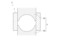
- FIG. 2 is a cross-sectional view showing an example of die press molding for explaining a method for filling a ceramic molded body according to an embodiment.
- FIG. 2 is a perspective view showing an example of a rubber mold laminate for explaining a method for filling a ceramic molded body according to an embodiment.
- FIG. 2 is a cross-sectional view showing an example of a rubber mold laminate filled with a pre-treatment molded body, for illustrating a method for filling a ceramic molded body according to an embodiment.
- FIG. 2 is a top view showing the configuration of a rubber mold laminate for explaining a method for filling a ceramic molded body according to an embodiment.
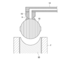
- FIG. 4 is a cross-sectional view for explaining a first step of the method for filling a ceramic molded body according to the embodiment.
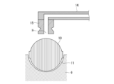
- FIG. 4 is a cross-sectional view for explaining a second step of the method for filling a ceramic molded body according to the embodiment.
- FIG. 11 is a cross-sectional view for explaining a third step of the method for filling a ceramic molded body according to the embodiment.
- FIG. 11 is a cross-sectional view illustrating a fourth step of the method for filling a ceramic molded body according to the embodiment.
- FIG. 13 is a cross-sectional view for explaining a fifth step of the method for filling a ceramic molded body according to the embodiment.
- FIG. 13 is a cross-sectional view for explaining a sixth step of the method for filling a ceramic molded body according to the embodiment.
- the rubber mold constituting the rubber mold laminate has multiple holes for filling multiple molded bodies.
- Figure 1 shows a ceramic ball material, for example a bearing ball material, obtained by sintering a compact formed by press molding.
- reference numeral 1 denotes the ceramic ball material
- reference numeral 2 denotes a spherical portion of the ceramic ball material
- reference numeral 3 denotes a band-shaped portion of the ceramic ball material 1.
- Figure 2 shows a press die for forming a pre-processed compact of the ceramic ball material 1 before sintering.
- reference numeral 4 denotes the press die
- reference numeral 5 denotes a punch portion
- reference numeral 5U denotes an upper punch of the punch portion
- reference numeral 5D denotes a lower punch of the punch portion
- reference numeral Y denotes a die.
- the band-shaped portion of the compact formed by the space between the tip of the upper punch 5U, the tip of the lower punch 5D, and the die Y corresponds to the band-shaped portion 3 of the ceramic ball material 1.
- Figure 3 is a perspective view showing an example of a rubber mold laminate in which three rubber molds are stacked.
- reference numeral 6 denotes a rubber mold laminate
- reference numeral 7 denotes an upper rubber mold
- reference numeral 8 denotes a middle rubber mold
- reference numeral 9 denotes a lower rubber mold.
- the rubber mold laminate 6 is not limited to the three-layer structure as shown in Figure 3, but may be a two-layer structure of an upper rubber mold 7 and a lower rubber mold 9 without a middle rubber mold 8, or may be a four-layer or greater structure with two or more middle rubber molds 8.
- Figure 4 is a cross-sectional view showing an example of a rubber mold laminate in which three rubber molds are stacked.
- reference numeral 6 denotes a rubber mold laminate
- reference numerals 7 to 9 denote rubber molds
- reference numeral 10 denotes a pre-processed molded body before sintering of the ceramic ball material 1 (shown in Figure 1)
- reference numeral 11 denotes a hole.
- the rubber mold laminate 6 for processing the pre-processed molded body 10 is a mold used in CIP molding.
- Each of the rubber molds 7 to 9 constituting the rubber mold laminate 6 is plate-shaped.
- plate-shaped means having a certain degree of thickness (height).
- a plurality of hemispherical holes 11 are provided on the bottom surface of the upper rubber mold 7, the top surface of the lower rubber mold 9, and the opposing top and bottom surfaces of the middle rubber mold 8.
- the plurality of holes 11 are arranged at positions where the opposing hemispherical holes 11 can be integrated to form a spherical shape.
- a number of pre-processed molded bodies 10 are placed on the lower rubber mold 9, the pre-processed molded bodies 10 are fitted into the holes 11 formed in the top surface of the lower rubber mold 9, and the middle rubber mold 8 is placed on the lower rubber mold 9.
- a number of pre-processed molded bodies 10 are placed on the stacked middle rubber mold 8, the pre-processed molded bodies 10 are fitted into the holes 11 formed in the top surface of the middle rubber mold 8, and the upper rubber mold 7 is placed on the middle rubber mold 8.
- the middle rubber mold 8 into which the pre-processed molded bodies 10 have been fitted beforehand is placed on the lower rubber mold 9, and the upper rubber mold 7 is placed on the rubber mold 8.
- each of the multiple holes 11 has an approximately hemispherical shape.
- the CIP body which is a molded body obtained by CIP treatment of the pre-treated molded body 10
- the hole 11 does not have an approximately hemispherical shape, but has an approximately cylindrical shape with an approximately circular opening.
- the CIP body may be based on the pre-treated molded body 10 obtained not only by die molding but also by rolling granulation or the like. If the CIP body is based on the pre-treated molded body 10 obtained by rolling granulation or the like, there is also a shape without a band portion.
- the pre-treated molded body 10 may or may not have a band portion.
- the pre-treated molded body 10 may or may not have a band portion 3 as shown in FIG. 1.
- the shape of the hole portion 11 is taken into consideration, and the side shape is not particularly limited.
- the raw compact 10, the CIP compact, and the degreased compact described below are examples of compacts.
- the rubber mold laminate 6 is intended for use in the CIP treatment of the pre-treatment molded body 10.
- CIP treatment There are two types of CIP treatment: WET-CIP and DRY-CIP.
- WET-CIP is a method in which the powder or pre-treatment molded body 10 is sealed in a bag or other material that has low deformation resistance and a certain level of strength, preventing contact with liquid, and then hydraulic pressure is applied.
- DRY-CIP is a pressurization method that uses a rubber mold laminate 6 and has a platform that supports the rubber mold laminate 6 at the bottom of the rubber mold laminate 6. These methods use hydraulic pressure to apply pressure, making it possible to mold with isotropic pressure that has no directionality. Because it is isotropic pressure, it is possible to suppress uneven density distribution within the pre-treatment molded body 10.
- CIP is also called cold isostatic pressing or rubber pressing. The use of the rubber mold laminate 6 produces more favorable results when DRY-CIP is used.
- the rubber molds 7 to 9 constituting the rubber mold laminate 6 are preferably plate-shaped, for example, substantially circular.
- a substantially circular shape refers to a circular or elliptical cylindrical shape with a relatively low height between the opposing top and bottom surfaces.
- the plate-shaped rubber molds 7 to 9 are not limited to a circular shape, and may have a polygonal shape, etc. When the rubber molds 7 to 9 have a polygonal shape, it is preferable that they have a pentagon or more.
- the rubber molds 7 to 9 may also have an engagement portion for connecting with adjacent rubber molds vertically. If the rubber molds 7 to 9 are circular, it is easy to align them when multiple rubber molds 7 to 9 are stacked vertically.
- the rubber molds 7 to 9 are circular, there is no directionality between the adjacent rubber molds 7 to 9, so it is easy to stack the rubber molds 7 to 9.
- the thickness (height) of each step of the rubber molds 7-9 is preferably 5 mm or more and 30 mm or less. If the rubber molds 7-9 are too thin, there is a higher risk of the rubber molds 7-9 deforming. If the rubber molds 7-9 deform, the rubber molds 7-9 will not engage with each other properly, and the rubber molds 7-9 may collapse when stacking the rubber molds 7-9 and when transporting the rubber mold laminate 6. Even if the rubber molds 7-9 do not collapse, the balance may become unbalanced, and problems may occur when transporting the rubber mold laminate 6. Furthermore, if the rubber molds 7-9 are deformed, it may be difficult to apply uniform pressure to the pre-treatment molded body 10 during CIP treatment.
- the number of layers of rubber molds constituting the rubber mold laminate 6 is not particularly limited (three layers are exemplified in Figs. 3 and 4), but 50 layers or less is preferable. If the number of layers of rubber molds is too large, the laminated multiple rubber molds may collapse when the rubber mold laminate 6 is transported to the CIP treatment device or removed from the CIP treatment device. Even if the laminated multiple rubber molds do not collapse, there is a possibility that the deterioration of the engagement parts due to lateral shaking that occurs during transportation of the rubber mold laminate 6 may be accelerated. Therefore, the more preferable number of layers of rubber molds constituting the rubber mold laminate 6 is 2 layers or more and 30 layers or less.
- the number of layers of rubber molds is 2 layers or more and 20 layers or less. Taking mass production and the like into consideration, it is even more preferable that the number of layers of rubber molds is 3 layers or more and 10 layers or less. In this specification, a case where the number of layers of rubber molds is three layers will be described as an example.
- the error in the height of the rubber molds 7-9 is less than 10%. If the error in the height of the rubber molds 7-9 is large, the rubber molds 7-9 may be prone to collapse during transportation of the rubber mold stack 6. It is also preferable that there is little error in the area of the stacking surfaces of the rubber molds 7-9. If there is a large error in the area of the stacking surfaces of the rubber molds 7-9, it may be difficult to apply uniform pressure during CIP treatment.
- recesses or protrusions may be provided on the side surfaces of the rubber molds 7 to 9, the top surface of the rubber mold 7, or the bottom surface of the rubber mold 9 (i.e., the non-hole surfaces that do not have holes 11) for the purpose of marking, reducing weight, etc.
- the shapes of the non-hole surfaces of the rubber molds 7 to 9 are not particularly limited.
- the Shore hardness Hs of the rubber of the rubber molds 7 to 9 is within the range of 30 to 50.
- isotropic pressure is applied to the rubber molds 7 to 9 filled with the raw molded body 10. If the Shore hardness Hs is within the range of 30 to 50, the amount of deformation can be made uniform. Therefore, the rubber molds 7 to 9 can be provided with the deformability to allow uniform contact between the surface of the raw molded body 10 and the rubber molds 7 to 9. The durability of the rubber molds 7 to 9 is also good.
- the Shore hardness Hs is measured in accordance with JIS-Z-2246 (2000).
- the method for filling the pre-processed molded bodies 10 includes a filling step in which a plurality of pre-processed molded bodies 10 are filled into a plurality of holes 11 by suction and transport.
- a filling step in which a plurality of pre-processed molded bodies 10 are filled into a plurality of holes 11 by suction and transport.
- Figure 5 is a top view showing an example of the top surface of the lower rubber die 9.
- the top and bottom surfaces of the middle rubber die 8 are similar to those in Figure 5.
- the bottom surface of the upper rubber die 7 is also similar to those in Figure 5.
- FIGS. 6 to 11 are diagrams for explaining a method of filling a rubber mold 8, 9 (e.g., lower rubber mold 9) having a hole 11 formed in the top surface with a pre-processed molded body 10.
- FIGS. 6 to 11 are cross-sectional views cut along a vertical plane including the center of the pre-processed molded body 10. Note that FIGS. 6 to 11 explain a method of filling the lower rubber mold 9 of the rubber molds 8, 9 with the pre-processed molded body 10 as an example.
- FIG. 6 shows the first step before the pre-processed molded body 10 is ejected from the lower punch 5D of the press die. The upper surface of the lower punch 5D reaches the upper surface of the die Y, and the band-shaped portion 10' of the pre-processed molded body 10 is positioned above the die Y.
- Figure 7 shows the second process in which the suction pad 15 attached to the suction arm 14 is suctioned to the spherical portion of the raw molded body 10.
- a hole H is opened in the center of the tip of the suction pad 15, which extends to the through hole along the axial direction of the suction arm 14. With the center of the tip of the suction pad 15 in contact with the raw molded body 10, the raw molded body 10 is further sucked through the hole H, and the center of the tip of the suction pad 15 is adsorbed to the raw molded body 10.
- FIG. 8 shows the third step in which the suction arm 14 moves upward with the pre-processed molded body 10 adsorbed thereon to lift the pre-processed molded body 10.
- FIG. 9 shows the fourth step in which the suction arm 14 moves above the lower rubber mold 9 with the pre-processed molded body 10 adsorbed thereon. In the fourth step, at least the suction arm 14 is moved so that the moved pre-processed molded body 10 is located almost directly above the hole 11 of the lower rubber mold 9.
- FIG. 10 shows the fifth step in which the suction arm 14 is lowered and then released from adsorption, and the pre-processed molded body 10 falls into the hole 11 of the lower rubber mold 9.
- Figure 11 shows the sixth step after the suction arm 14 has been retracted.
- the material of the suction pad 15 is preferably an elastic body such as elastic rubber.
- the hardness is 70° or less. If the hardness exceeds 70°, it will not deform when adsorbing to the raw molded body 10, and the adhesion with the raw molded body 10 will be poor, and it may not be possible to adsorb the raw molded body 10 well.
- the suction pad 15 in the suction state shown in FIG. 7 to FIG. 9 has its tip deformed to match the shape of the raw molded body 10 compared to the suction pad 15 in the non-adsorption state shown in FIG. 10.
- the pre-processed molded body 10 has been dropped from the state shown in Figure 9 into the hole 11 of the lower rubber mold 9.
- the drop distance L (shown in Figure 9) of the pre-processed molded body 10 is preferably 50 mm or less.
- the drop distance L means the height of the bottom end of the pre-processed molded body 10 before it is dropped relative to the plane of the top surfaces of the rubber molds 8 and 9. If the drop distance L exceeds 50 mm, the pre-processed molded body 10 will be damaged by impact. For this reason, the preferred drop distance L is 30 mm or less, and the more preferred drop distance L is 15 mm or less.
- the raw molded body 10 has a maximum diameter of 5.0 mm or more.
- the pre-processed molded body 10 When the pre-processed molded body 10 is press molded by applying pressure from above and below, the applied pressure is set low to obtain the desired shape at a low density, and then in the subsequent CIP process, pressure is applied at an equal pressure to increase the density, thereby making the CIP body uniform. In some cases, the pre-processed molded body 10 is placed on the lower rubber mold 9 and rotated to fill the holes 11 with the pre-processed molded body 10.
- the pre-processed molded body 10 is light, so even if the pre-processed molded body 10 rolls on the lower rubber mold 9, it will not rub against the surface of the lower rubber mold 9 and will not be worn down, and even if the pre-processed molded bodies 10 collide with each other, they will hardly be damaged.
- the pre-processed molded body 10 is heavy, and when the pre-processed molded body 10 rolls on the lower rubber mold 9, the pre-processed molded body 10 is likely to rub against the surface of the lower rubber mold 9 and become worn, and the pre-processed molded bodies 10 are likely to collide with each other and become damaged. At this time, the corners of the band-shaped portion 10' (shown in FIG. 6) formed protruding from the spherical portion may be rubbed or crushed. The weight of the pre-processed molded body 10 increases in proportion to the diameter.
- the yield is better when processing pre-processed molded bodies 10 with a large diameter, and the effect of the filling method of FIG. 6 to FIG. 11 is greater.
- the maximum diameter of the pre-processed molded body 10 is more preferably 7.0 mm or more, and even more preferably 10.0 mm or more.
- the pre-processed body 10 may have a spherical, cylindrical, plate-like, or other shape.
- the pre-processed body 10 is preferably spherical in order to manufacture a spherical ceramic ball material 1, as shown in FIG. 1.
- the spherical shape refers to a shape having a spherical surface portion 2 and a band-like portion 3, as in the ceramic ball material 1 with a band-like portion (shown in FIG. 1), or a shape having only a spherical surface portion, as in the ceramic ball material without a band-like portion (not shown).
- isotropic pressure can be applied to the pre-processed body 10.
- the effect of isotropic pressure can be obtained more easily when the pre-processed body 10 has a spherical shape.
- the total amount of ceramic powder in the raw compact 10 is 80 mass% or more, and the amount of binder is 3 mass% or more and 20 mass% or less.
- the raw compact 10 preferably contains at least one of aluminum oxide (alumina), silicon nitride, boron nitride, zirconium oxide (zirconia), silicon carbide, and aluminum nitride as the main component (50% by mass or more) contained in the ceramic powder. It is more preferable that the raw compact 10 contains at least one of aluminum oxide, silicon nitride, boron nitride, zirconium oxide, silicon carbide, and aluminum nitride in an amount of at least 85% by mass.
- the raw compact 10 is degreased as necessary and then sintered to become a ceramic sintered body (hereinafter, sometimes simply referred to as a "sintered body").
- the ceramic sintered body also has a ball shape.
- the ball-shaped ceramic sintered body is also called a ceramic ball material 1 and is used as a bearing ball.
- the bearing ball is manufactured by polishing the ceramic ball material 1.
- the silicon nitride sintered body has excellent wear resistance and is effective as a bearing ball.
- the ceramic powder of the pre-treated compact 10 contains at least 85 mass% of any one of aluminum oxide, silicon nitride, boron nitride, and zirconium oxide
- the resulting ceramic sintered body also contains at least 85 mass% of any one of aluminum oxide, silicon nitride, boron nitride, and zirconium oxide.
- it may also contain up to 15 mass% of a sintering aid.
- the aluminum oxide sintered body or the zirconium oxide sintered body has a Vickers hardness of about 1200 to 1700.
- the toughness value is low, about 3 MPa ⁇ m 1/2 to 6 MPa ⁇ m 1/2 .
- the silicon nitride sintered body has a Vickers hardness of about 1400 to 1800.
- the toughness value is high, about 5 MPa ⁇ m 1/2 to 10 MPa ⁇ m 1/2 .
- the silicon nitride sintered body has both a high toughness value and a Vickers hardness, and is therefore excellent in wear resistance. This is because the silicon nitride sintered body has a structure mainly composed of ⁇ -type silicon nitride crystal particles.
- the ⁇ -type silicon nitride crystal particles have a long and thin shape, and the long and thin crystal particles are intricately intertwined to achieve a high toughness value.
- Ceramic ball material 1 is a sphere with band-shaped portion 3 resulting from the band-shaped portion of pre-treatment compact 10.
- ceramic ball material 1 may also be a sphere without band-shaped portion 3 resulting from the band-shaped portion of pre-treatment compact 10.
- Ceramic ball material 1 polished to a sphere is called a bearing ball.
- the rubber mold laminate 6 is suitable for applying isotropic pressure to the pre-processed molded body 10.
- the rubber mold laminate 6 is suitable for subjecting the pre-processed molded body 10 to CIP processing.
- the bearing balls come in a variety of diameters ranging from 1.0 mm to 50.0 mm.
- the rubber mold laminate 6 can be applied to pre-processed molded bodies 10 of various sizes.
- the method for manufacturing the ceramic ball material 1 uses the filling method of the pre-processed compact 10 described above.
- the manufacturing method of the CIP body also includes a process of filling a plurality of pre-processed molded bodies 10 into a plurality of holes 11 formed in the rubber molds 8 and 9, and then stacking them to form the rubber mold laminate 6, as well as a process of performing CIP processing on the filled plurality of pre-processed molded bodies 10.
- the method for producing a ceramic sintered body also includes a step of filling a plurality of pre-processed compacts 10 into a plurality of holes 11 formed in the rubber molds 8 and 9, stacking them to form a rubber mold laminate 6, a step of CIP-processing the filled pre-processed compacts 10, and a step of sintering the CIP bodies to obtain a ceramic sintered body.
- the ceramic sintered body is ball-shaped, it becomes a ceramic ball material 1.
- the manufacturing method for a ceramic sintered body for example, material 1 for ceramic balls, should have the above configuration, but a method for improving the yield (number of good products/number manufactured) is described below.
- the method for preparing the raw green body 10 will be explained using silicon nitride.
- silicon nitride When one or more of aluminum oxide, boron nitride, and zirconium oxide are used as the main component (50 mass% or more), silicon nitride should be read as a substitute.
- uniaxial pressure molding is given as a method for obtaining the raw green body 10, but the molding method is not limited to this.
- the molding method may be rolling granulation.
- sintering aid powder an appropriate amount of sintering aid powder, additives, solvent, binder, etc. is added to the silicon nitride powder as the raw material, mixed, crushed, and granulated using a spray dryer. This process prepares granulated powder from the raw powder.
- the silicon nitride powder is 85 mass% or more.
- the additive is a plasticizer, etc.
- the solvent is water or an organic solvent. Examples of organic solvents include alcohol, ketone, and benzene.
- the binder is an organic substance.
- the amount of binder added is preferably 3 mass parts or more and 20 mass parts or less when the total of the silicon nitride powder and the sintering aid powder is 100 mass parts.
- the amount of binder it is possible to adjust the uniaxial pressing, the shape retention, and the density uniformity of the pre-processed molded body 10.
- the silicon nitride powder and the sintering aid powder can be mixed uniformly.
- uniaxial pressure molding is performed using the granulated powder.
- One example of uniaxial pressure molding is a die molding method using an upper punch 5U and a lower punch 5D as shown in FIG. 2.
- the shape of the pre-processed compact 10 can be adjusted depending on the shape of the die.
- a spherical pre-processed compact 10 can be obtained.
- a roller-shaped (approximately cylindrical) pre-processed compact 10 can be obtained.
- the pre-processed compact 10 obtained by uniaxial pressure molding corresponds to the ceramic ball material 1 before sintering, which has a spherical shape with a spherical portion 2 and a band-shaped portion 3 as shown in FIG. 1.
- the pre-processed molded body 10 is subjected to a CIP process.
- the rubber mold laminate 6 is used when performing the CIP process.
- a plurality of pre-processed molded bodies 10 are filled into a plurality of holes 11 formed in the rubber molds 8 and 9 constituting the rubber mold laminate 6, for example, the lower rubber mold 9.
- the number of pre-processed molded bodies 10 that can be processed can be increased.
- filling all of the holes 11 with the pre-processed molded body 10 is more likely to homogenize the isotropic pressure.
- the raw green body 10 is formed using granulated powder.
- isotropic pressure is applied to the raw green body 10 by CIP treatment, the granulated powder is crushed, and density variation can be suppressed.
- the silicon nitride powder and sintering aid powder are uniformly dispersed, and density variation can be suppressed. If the pressure applied to the raw green body 10 during CIP treatment is uneven, the granulated powder will not be crushed and will remain. The remaining uncrushed parts will cause density variation.
- the pressure of the CIP molding is preferably higher than the pressing pressure of uniaxial pressure molding.
- the conditions of the CIP treatment are preferably within a pressure range of 30 MPa to 300 MPa. If the pressure is within this range, the density variation of the CIP body after the CIP treatment can be reduced. This is particularly effective when the rubber molds 7 to 9 constituting the rubber mold laminate 6 have a Shore hardness Hs of 30 to 50. If the CIP pressure is less than 30 MPa, the pressure may be insufficient. Furthermore, if the pressure is high, exceeding 300 MPa, the durability of the rubber molds 7 to 9 may decrease.
- a degreasing process is performed to degrease the CIP body.
- the degreasing process involves heating the CIP body at a temperature equal to or higher than the decomposition temperature of the organic components such as binders to remove the organic components.
- the degreasing process may be performed in a nitrogen atmosphere or in the air.
- a degreased body can be obtained as a molded body by the degreasing process.
- a sintering process is carried out to sinter the degreased body.
- the sintering process is preferably carried out at a temperature of 1700°C or higher and 2000°C or lower.
- the sintering process is preferably carried out in a nitrogen atmosphere.
- the sintered body obtained by the sintering process may be subjected to HIP (hot isostatic pressing) treatment. This process makes it possible to obtain a ceramic sintered body (e.g., ceramic ball material 1).
- the ceramic ball material 1 is a ceramic sintered body with a theoretical density of 98% or higher.
- Ceramic balls can be manufactured by polishing the ceramic ball material 1.
- a typical example of polishing a ball is plate processing.
- the ceramic ball material 1 is inserted between parallel platens.
- the movement of the polishing platen processes the ceramic ball material 1 into a perfect sphere.
- the surface roughness of bearing balls is stipulated in ASTM_F2094.
- ASTM_F2094 the grade of bearing balls that conform to ASTM_F2094, ISO26602, or JIS R1669 is adopted.
- the balls are polished to a surface roughness Ra that conforms to that grade.
- Higher grades can be mirror-finished to a surface roughness Ra of 0.01 ⁇ m or less.
- Example 1 to 9 Sintering aids, additives, solvents, binders, etc. were added to the raw ceramic powder, mixed, crushed, and granulated by a spray dryer.
- Examples 1 to 5 and Comparative Examples 1 and 2 correspond to the pre-treatment molded body (silicon nitride molded body) 10 containing 85% by mass or more of silicon nitride
- Examples 6 to 7 and Comparative Examples 3 and 4 correspond to the pre-treatment molded body (aluminum oxide molded body) 10 containing 85% by mass or more of aluminum oxide (alumina)
- Examples 8 to 9 and Comparative Examples 5 and 6 correspond to the pre-treatment molded body (zirconium oxide molded body) 10 containing 85% by mass or more of zirconium oxide (zirconia).
- the amount of the binder added was 3 parts by mass or more and 20 parts by mass or less.
- aluminum oxide is written as alumina
- zirconium oxide is written as zirconia.
- press molding was performed using the granulated powder.
- Press molding was performed by die molding using upper and lower punches 5U and 5D in the press die 4 shown in Figure 2.
- Press molding using the upper punch 5U and lower punch 5D was uniaxial pressure molding.
- the die was used to create a spherical pre-processed compact 10.
- the pre-processed compact 10 used in the examples corresponds to the ceramic ball material 1 with a band-shaped portion, which has a spherical portion 2 and a band-shaped portion 3, as shown in Figure 1.
- the pre-processed compact 10 is similar even if it corresponds to a ceramic ball material without a band-shaped portion (not shown) which has only the spherical portion 2.
- Rubber molds 7 to 9 were prepared for CIP processing of the raw molded body 10.
- the rubber molds 7 to 9 used had a Shore hardness Hs of 30 to 50.
- multiple hemispherical holes 11 were provided in the bottom surface of the upper rubber mold 7, the top surface of the lower rubber mold 9, and the top and bottom surfaces of the middle rubber mold 8.
- the pre-processed molded body 10 was adsorbed from the press die 4 and moved to the lower rubber die 9 by the manufacturing process shown in Figures 6 to 11.
- the filling methods of Comparative Examples 1 to 6 1.2 times the number of pre-processed molded bodies as the number of holes formed in the lower rubber die were introduced, and the lower rubber die was rotated to fill the holes with the pre-processed molded bodies.
- the filling method for the pre-processed molded bodies is indicated as adsorption or rotation.
- the falling distance L of the pre-processed molded body 10 to the lower rubber die 9 was adjusted.
- a middle rubber mold 8 filled with pre-processed molded bodies 10 was stacked on top of a lower rubber mold 9 filled with pre-processed molded bodies 10, and an upper rubber mold 7 was stacked on top of the middle rubber mold 8 to form a rubber mold laminate 6.
- a CIP process was performed on the filled pre-processed molded bodies 20.
- the CIP pressure was within the range of 30 MPa to 300 MPa, and a hydrostatic pressure higher than the pressure of uniaxial pressure molding was applied.
- a CIP body was produced by this process.
- the CIP bodies which are the molded bodies after CIP processing, were visually inspected using an optical microscope, and the number of CIP bodies with chipping defects was counted to determine the chipping defect rate.
- the chipping defect rate is shown in Table 1.
- the ceramic ball material 1 produced from the unprocessed compact 10 of Examples 1 to 14 and Comparative Examples 1 to 3 was used to carry out an appearance inspection of the sintered body before polishing.
- Examples 1 to 3, 6, and 8 and Comparative Examples 1, 3, and 5 shown in Table 1 correspond to ceramic ball materials for ceramic balls that will be 11/32 inches (8.73 mm) after polishing. Also, Examples 4 to 5, 7, and 9 and Comparative Examples 2, 4, and 6 correspond to ceramic ball materials for ceramic balls that are 7/8 inches (22.225 mm). All of them can be used as bearing balls.
- the chipping defect rate in the filling method according to the embodiment was low.
- the chipping defect rate in the filling method according to the comparative example was higher than that of the embodiment. This is because, in the filling method according to the embodiment, the pre-treated molded bodies 10 were adsorbed and filled, so that the pre-treated molded bodies 10 did not collide with each other, and no rubbing occurred with the rubber molds 8 and 9. In contrast, in the filling method according to the comparative example, the pre-treated molded bodies were filled by rotating them on the rubber mold, which caused collisions between the pre-treated molded bodies and rubbing of the rubber mold, resulting in more chipping defects.
Landscapes
- Engineering & Computer Science (AREA)
- Chemical & Material Sciences (AREA)
- Mechanical Engineering (AREA)
- Ceramic Engineering (AREA)
- Manufacturing & Machinery (AREA)
- Materials Engineering (AREA)
- Structural Engineering (AREA)
- Organic Chemistry (AREA)
- Physics & Mathematics (AREA)
- Fluid Mechanics (AREA)
- Devices For Post-Treatments, Processing, Supply, Discharge, And Other Processes (AREA)
Priority Applications (2)
| Application Number | Priority Date | Filing Date | Title |
|---|---|---|---|
| CN202480063118.0A CN121941594A (zh) | 2023-10-06 | 2024-09-27 | 陶瓷成形体的填充方法、cip体的制造方法、陶瓷烧结体的制造方法及陶瓷球用原材料的制造方法 |
| JP2025550248A JPWO2025074956A1 (https=) | 2023-10-06 | 2024-09-27 |
Applications Claiming Priority (2)
| Application Number | Priority Date | Filing Date | Title |
|---|---|---|---|
| JP2023-173969 | 2023-10-06 | ||
| JP2023173969 | 2023-10-06 |
Publications (1)
| Publication Number | Publication Date |
|---|---|
| WO2025074956A1 true WO2025074956A1 (ja) | 2025-04-10 |
Family
ID=95283317
Family Applications (1)
| Application Number | Title | Priority Date | Filing Date |
|---|---|---|---|
| PCT/JP2024/034767 Pending WO2025074956A1 (ja) | 2023-10-06 | 2024-09-27 | セラミックス成形体の充填方法、cip体の製造方法、セラミックス焼結体の製造方法、及び、セラミックスボール用素材の製造方法 |
Country Status (3)
| Country | Link |
|---|---|
| JP (1) | JPWO2025074956A1 (https=) |
| CN (1) | CN121941594A (https=) |
| WO (1) | WO2025074956A1 (https=) |
Citations (6)
| Publication number | Priority date | Publication date | Assignee | Title |
|---|---|---|---|---|
| JPH0373310A (ja) * | 1989-05-16 | 1991-03-28 | Toshiba Corp | セラミックス焼結体の製造方法 |
| JPH08236527A (ja) * | 1995-02-22 | 1996-09-13 | Matsushita Electric Ind Co Ltd | バンプ形成方法とその装置 |
| JPH1140568A (ja) * | 1997-07-18 | 1999-02-12 | Nippon Steel Corp | バンプの形成装置及び方法 |
| JP2002036216A (ja) * | 2000-07-21 | 2002-02-05 | Ngk Spark Plug Co Ltd | セラミックボール、ボールベアリング、ベアリング付きモータ、ハードディスク装置、ポリゴンスキャナ及びセラミックボールの製造方法 |
| JP2020196021A (ja) * | 2019-05-31 | 2020-12-10 | 日本特殊陶業株式会社 | 取り出し装置およびロータリープレスユニット |
| WO2023003040A1 (ja) * | 2021-07-21 | 2023-01-26 | 株式会社 東芝 | 冷間等方圧成形用ゴム型、セラミックスボール用素材の製造方法、および、セラミックスボールの製造方法 |
-
2024
- 2024-09-27 JP JP2025550248A patent/JPWO2025074956A1/ja active Pending
- 2024-09-27 CN CN202480063118.0A patent/CN121941594A/zh active Pending
- 2024-09-27 WO PCT/JP2024/034767 patent/WO2025074956A1/ja active Pending
Patent Citations (6)
| Publication number | Priority date | Publication date | Assignee | Title |
|---|---|---|---|---|
| JPH0373310A (ja) * | 1989-05-16 | 1991-03-28 | Toshiba Corp | セラミックス焼結体の製造方法 |
| JPH08236527A (ja) * | 1995-02-22 | 1996-09-13 | Matsushita Electric Ind Co Ltd | バンプ形成方法とその装置 |
| JPH1140568A (ja) * | 1997-07-18 | 1999-02-12 | Nippon Steel Corp | バンプの形成装置及び方法 |
| JP2002036216A (ja) * | 2000-07-21 | 2002-02-05 | Ngk Spark Plug Co Ltd | セラミックボール、ボールベアリング、ベアリング付きモータ、ハードディスク装置、ポリゴンスキャナ及びセラミックボールの製造方法 |
| JP2020196021A (ja) * | 2019-05-31 | 2020-12-10 | 日本特殊陶業株式会社 | 取り出し装置およびロータリープレスユニット |
| WO2023003040A1 (ja) * | 2021-07-21 | 2023-01-26 | 株式会社 東芝 | 冷間等方圧成形用ゴム型、セラミックスボール用素材の製造方法、および、セラミックスボールの製造方法 |
Also Published As
| Publication number | Publication date |
|---|---|
| CN121941594A (zh) | 2026-04-28 |
| JPWO2025074956A1 (https=) | 2025-04-10 |
Similar Documents
| Publication | Publication Date | Title |
|---|---|---|
| US9711280B2 (en) | Method for preparing rare earth sintered magnet | |
| US20240149546A1 (en) | Rubber mold for cold isostatic pressing, method of manufacturing ceramic ball material, and method of manufacturing ceramic ball | |
| CN1907603A (zh) | 粉末冶金内螺旋棘轮的制造方法及模具 | |
| CN115551818A (zh) | 陶瓷烧结体的制造方法和陶瓷烧结体 | |
| JP7707388B2 (ja) | セラミックスボール用素材およびそれを用いたセラミックスボールの製造方法並びにセラミックスボール | |
| CN110550951A (zh) | 一种陶瓷盖板制备工艺 | |
| KR20200069398A (ko) | 박형 세라믹 기판의 소성용 적층 구조체 및 이를 이용한 박형 세라믹 기판의 제조방법 | |
| WO2025074956A1 (ja) | セラミックス成形体の充填方法、cip体の製造方法、セラミックス焼結体の製造方法、及び、セラミックスボール用素材の製造方法 | |
| JP7646952B2 (ja) | セラミックスボール用素材およびそれを用いたセラミックスボールの製造方法並びにセラミックスボール | |
| WO2015151824A1 (ja) | 圧縮成形装置および圧縮成形体の製造方法 | |
| WO2025057846A1 (ja) | セラミックス成形体の充填方法、cip体の製造方法、及び、セラミックス焼結体の製造方法 | |
| WO2021158472A1 (en) | Additive manufacturing of hollow or partially hollow rolling elements | |
| KR102464543B1 (ko) | 졸-갤 캐스팅 성형법을 이용하여 제조한 도전성 이산화티타늄 소결체 및 이의 제조방법 | |
| KR0139551B1 (ko) | 다층 적재 핫프레싱법에 의한 세라믹스의 소결방법 | |
| KR100872905B1 (ko) | 그룹화 연마제품의 가공장치 | |
| WO2025135035A1 (ja) | セラミックスセッター、セラミックスボール用素材の製造方法、およびセラミックスボールの製造方法 | |
| EP4534868A1 (en) | Material for ceramic ball, method for producing ceramic ball using same, and ceramic ball | |
| JP7216611B2 (ja) | SiC焼結部材の製造方法 | |
| KR101130716B1 (ko) | 나노 질화규소계 세라믹스의 제조방법 | |
| CN1569365A (zh) | 一种粉末原料制造球形体的方法 | |
| CN112958683A (zh) | 一种复合材料成形装置及成形方法 | |
| JP3380703B2 (ja) | セラミックボールの製造方法 | |
| JP2005123556A (ja) | ウエーハ研磨用吸着プレート | |
| KR102886343B1 (ko) | 3d 프린팅을 이용한 투명 세라믹 3차원 구조체의 제조방법 | |
| WO2025033302A1 (ja) | タングステン焼結体 |
Legal Events
| Date | Code | Title | Description |
|---|---|---|---|
| 121 | Ep: the epo has been informed by wipo that ep was designated in this application |
Ref document number: 24874560 Country of ref document: EP Kind code of ref document: A1 |
|
| ENP | Entry into the national phase |
Ref document number: 2025550248 Country of ref document: JP Kind code of ref document: A |
|
| WWE | Wipo information: entry into national phase |
Ref document number: 2025550248 Country of ref document: JP |