WO2025057666A1 - 熱交換器 - Google Patents
熱交換器 Download PDFInfo
- Publication number
- WO2025057666A1 WO2025057666A1 PCT/JP2024/029386 JP2024029386W WO2025057666A1 WO 2025057666 A1 WO2025057666 A1 WO 2025057666A1 JP 2024029386 W JP2024029386 W JP 2024029386W WO 2025057666 A1 WO2025057666 A1 WO 2025057666A1
- Authority
- WO
- WIPO (PCT)
- Prior art keywords
- region
- fin
- grooves
- tubes
- tube
- Prior art date
- Legal status (The legal status is an assumption and is not a legal conclusion. Google has not performed a legal analysis and makes no representation as to the accuracy of the status listed.)
- Pending
Links
Images






Classifications
-
- F—MECHANICAL ENGINEERING; LIGHTING; HEATING; WEAPONS; BLASTING
- F28—HEAT EXCHANGE IN GENERAL
- F28D—HEAT-EXCHANGE APPARATUS, NOT PROVIDED FOR IN ANOTHER SUBCLASS, IN WHICH THE HEAT-EXCHANGE MEDIA DO NOT COME INTO DIRECT CONTACT
- F28D1/00—Heat-exchange apparatus having stationary conduit assemblies for one heat-exchange medium only, the media being in contact with different sides of the conduit wall, in which the other heat-exchange medium is a large body of fluid, e.g. domestic or motor car radiators
- F28D1/02—Heat-exchange apparatus having stationary conduit assemblies for one heat-exchange medium only, the media being in contact with different sides of the conduit wall, in which the other heat-exchange medium is a large body of fluid, e.g. domestic or motor car radiators with heat-exchange conduits immersed in the body of fluid
- F28D1/04—Heat-exchange apparatus having stationary conduit assemblies for one heat-exchange medium only, the media being in contact with different sides of the conduit wall, in which the other heat-exchange medium is a large body of fluid, e.g. domestic or motor car radiators with heat-exchange conduits immersed in the body of fluid with tubular conduits
- F28D1/053—Heat-exchange apparatus having stationary conduit assemblies for one heat-exchange medium only, the media being in contact with different sides of the conduit wall, in which the other heat-exchange medium is a large body of fluid, e.g. domestic or motor car radiators with heat-exchange conduits immersed in the body of fluid with tubular conduits the conduits being straight
-
- F—MECHANICAL ENGINEERING; LIGHTING; HEATING; WEAPONS; BLASTING
- F28—HEAT EXCHANGE IN GENERAL
- F28F—DETAILS OF HEAT-EXCHANGE AND HEAT-TRANSFER APPARATUS, OF GENERAL APPLICATION
- F28F1/00—Tubular elements; Assemblies of tubular elements
- F28F1/02—Tubular elements of cross-section which is non-circular
-
- F—MECHANICAL ENGINEERING; LIGHTING; HEATING; WEAPONS; BLASTING
- F28—HEAT EXCHANGE IN GENERAL
- F28F—DETAILS OF HEAT-EXCHANGE AND HEAT-TRANSFER APPARATUS, OF GENERAL APPLICATION
- F28F1/00—Tubular elements; Assemblies of tubular elements
- F28F1/10—Tubular elements and assemblies thereof with means for increasing heat-transfer area, e.g. with fins, with projections, with recesses
- F28F1/12—Tubular elements and assemblies thereof with means for increasing heat-transfer area, e.g. with fins, with projections, with recesses the means being only outside the tubular element
- F28F1/24—Tubular elements and assemblies thereof with means for increasing heat-transfer area, e.g. with fins, with projections, with recesses the means being only outside the tubular element and extending transversely
- F28F1/30—Tubular elements and assemblies thereof with means for increasing heat-transfer area, e.g. with fins, with projections, with recesses the means being only outside the tubular element and extending transversely the means being attachable to the element
-
- F—MECHANICAL ENGINEERING; LIGHTING; HEATING; WEAPONS; BLASTING
- F28—HEAT EXCHANGE IN GENERAL
- F28F—DETAILS OF HEAT-EXCHANGE AND HEAT-TRANSFER APPARATUS, OF GENERAL APPLICATION
- F28F13/00—Arrangements for modifying heat-transfer, e.g. increasing, decreasing
- F28F13/18—Arrangements for modifying heat-transfer, e.g. increasing, decreasing by applying coatings, e.g. radiation-absorbing, radiation-reflecting; by surface treatment, e.g. polishing
Definitions
- This disclosure relates to a heat exchanger.
- heat exchangers are known that include a first fluid flowing through a tube and fins that promote heat exchange between the first fluid and a second fluid flowing outside the tube.
- condensation occurs depending on the load condition of the heat exchanger, and the condensation may accumulate on the outer surface of the fins. Therefore, in order to improve the drainage of the fins, a heat exchanger with grooves provided on the entire surface of the fins has been proposed, for example, in Patent Document 1.
- condensation water generated on the outer surface of the fins forms a water film all over the surface, which tends to connect, and is easily drained into the tubes through the grooves.
- the amount of condensation water generated in the heat exchanger is small.
- condensation water that runs down the tubes and accumulates at the joints between the fins and the tubes is drawn into the center of the fins by capillary action in the grooves, and the condensation water remains on the outer surface of the fins.
- the grooves which are intended to improve the drainage of condensation water, actually reduce drainage when the refrigeration cycle is operating at low load.
- the present disclosure aims to provide a heat exchanger that can suppress odors while ensuring the drainage properties of the fins in situations where condensed water evaporates all at once.
- the heat exchanger includes a tube through which a first fluid flows, and fins formed by bending a plate-like member and promoting heat exchange between the first fluid and a second fluid flowing outside the tube.
- the outer surface of the fin has a first region and a second region that is more hydrophilic than the first region.
- the second region has grooves formed to improve the hydrophilicity of the outer surface.
- the second region is disposed adjacent to a portion of the joint between the tube and the fin.
- the only highly hydrophilic area of the outer surface of the fin adjacent to the junction between the tube and the fin is the second area. This makes it possible to reduce the area into which condensed water is drawn, compared to when the condensed water is drawn into the entire area adjacent to the junction by the groove.
- the evaporation rate of the condensed water can be slowed down in the area of the outer surface of the fin located adjacent to the joint between the tube and the fin. This makes it possible to prevent the odorous components contained in the condensed water from being released all at once in situations where the condensed water evaporates all at once. Also, in situations where a lot of condensed water is generated, the condensed water can be drained into the tube through the grooves in the fin.
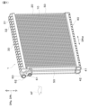
- FIG. 1 is a perspective view of a heat exchanger according to a first embodiment
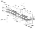
- FIG. 2 is an enlarged perspective view of a portion of the tubes and fins of the heat exchanger of FIG. 1
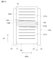
- FIG. 3 is a view taken along the arrow III in FIG. 2
- FIG. 4 is an enlarged plan view showing a groove by enlarging a part of a joint between a tube and a fin in a second region of an outer surface of the fin in the first embodiment
- FIG. 5 is a cross-sectional view showing a V-V cross section of FIG. FIG.
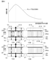
- FIG. 6 is a diagram for explaining a high drainage mode in which a large amount of condensed water is generated, in which the upper part shows the amount of condensed water corresponding to the position in the air passing direction, the middle part shows a drainage mode in which a groove portion is formed in a part of the outer surface of the fin, and the lower part shows a drainage mode in which a groove portion is not formed in the outer surface of the fin.
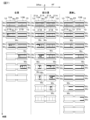
- FIG. 7 is a diagram for explaining how condensed water generated in a heat exchanger evaporates in the cases where grooves are provided on the entire outer surface of the fin, where grooves are provided on only a part of the outer surface of the fin, and where no grooves are provided on the outer surface of the fin; FIG.
- FIG. 8 is a graph showing the relationship between the evaporation rate of condensed water and the time until evaporation of the condensed water is completed in the cases where grooves are provided on the entire outer surface of the fin, where grooves are provided on only a portion of the outer surface of the fin, and where no grooves are provided on the outer surface of the fin;
- FIG. 9 is a perspective view showing how a large amount of odorous components are released when grooves are formed over the entire outer surface of the fin;
- FIG. 10 is a perspective view showing how a fin emits less odorous components when a groove is formed in a part of the outer surface of the fin.
- FIG. 11 is a plan view illustrating a groove portion formed in a second region in the second embodiment;
- FIG. 12 is a plan view illustrating a groove portion formed in a second region in the second embodiment
- FIG. 13 is a plan view illustrating a groove portion formed in a second region in the second embodiment
- FIG. 14 is a diagram showing a groove portion formed in a second region in the second embodiment
- FIG. 15 is an enlarged cross-sectional view showing some grooves formed in the first region and the second region in the third embodiment
- FIG. 16 is an enlarged plan view showing some grooves formed in the first region and the second region in the third embodiment
- FIG. 17 is an enlarged plan view showing some of the grooves formed in the first region and the second region in the third embodiment.
- the heat exchanger according to the present embodiment is used, for example, as an evaporator constituting a part of a refrigeration cycle for conditioning the air in a vehicle cabin.
- the refrigeration cycle includes, for example, a compressor, a condenser, an expansion valve, and an evaporator.
- the evaporator is disposed inside an air conditioning case through which air flows to be blown into the vehicle cabin.
- the evaporator therefore exchanges heat between the low-pressure refrigerant, the first fluid of the refrigeration cycle that has been decompressed by the expansion valve, and the blown air, the second fluid that flows through the air conditioning case, and cools the blown air by having the low-pressure refrigerant absorb heat from the blown air.
- the evaporator is a cooling heat exchanger that cools the air using the latent heat of evaporation of the refrigerant.
- the heat exchanger 1 includes a plurality of tubes 10, a plurality of fins 20, a first tank portion 30, a second tank portion 40, an outer frame member 50, and a piping connection member 60. These members are made of, for example, an aluminum alloy, and the respective members are joined together by brazing.
- the arrow DRg in Fig. 1 indicates the up-down direction DRg of the heat exchanger 1.
- a plurality of grooves 22 are formed on the outer surface 21 of the fin 20.
- the grooves 22 are extremely small compared to the size of the fin 20, they are not shown in Figures 2 and 3. This is also true for other figures showing the fin 20 described below, except for the figures in which the grooves 22 are enlarged.
- the multiple tubes 10 are arranged at a predetermined interval in the tube arrangement direction DRst.
- the air passing through the heat exchanger 1 flows between the multiple tubes 10. That is, the air flows between adjacent tubes 10 in the tube arrangement direction DRst. Between the tubes 10, the air flows with one side of the air passage direction AF as the upstream side (upwind) and the other side of the air passage direction AF as the downstream side (downwind).
- the air passage direction AF is the second fluid flow direction.
- the air passing through the heat exchanger 1 is cooled by the refrigerant as it flows between the tubes 10, generating condensed water.
- the air passing through the heat exchanger 1 is a gas that generates condensed water through heat exchange with the refrigerant.
- the tubes 10 are flat tubes having a flat cross-sectional shape with the tube arrangement direction DRst as the short side direction and the air passage direction AF as the long side direction.
- the multiple tubes 10 constitute a first arrangement group 10A and a second arrangement group 10B arranged in the tube arrangement direction DRst that intersects with the tube extension direction DRt.
- the tube extension direction DRt is the direction in which the tubes 10 extend.
- the first array group 10A and the second array group 10B are aligned in the air passage direction AF.
- the multiple tubes 10 are aligned in two rows, one on one side of the air passage direction AF and the other on the other side.
- the first array group 10A is located on the upstream side of the air flow
- the second array group 10B is located on the downstream side of the air flow.
- each of the multiple tubes 10 is formed to extend linearly from one end to the other along the tube extension direction DRt.
- a refrigerant flows inside each tube 10.
- the tube extension direction DRt does not necessarily have to coincide with the up-down direction DRg.
- the tube extension direction DRt coincides with the up-down direction DRg.
- Each of the tubes 10 in this embodiment extends in the up-down direction DRg, i.e., the vertical direction DRg.
- the air passage direction AF, the tube arrangement direction DRst, and the tube extension direction DRt are directions that intersect with each other, and strictly speaking, are directions that are perpendicular to each other.
- the upper ends of the multiple tubes 10 are inserted into the first tank section 30, and the lower ends are inserted into the second tank section 40.
- the first tank section 30 and the second tank section 40 distribute the refrigerant to the multiple tubes 10 and collect the refrigerant flowing in from the multiple tubes 10.
- Each tank section 30, 40 is formed in a cylindrical shape using the same material as the tube 10.
- Each tank section 30, 40 is formed in a shape that extends in the tube arrangement direction DRst. Note that the term "cylindrical” includes not only a cylindrical shape but also a polygonal cylindrical shape such as a square cylindrical shape.
- the internal space of the first tank section 30 is divided into an upstream side and a downstream side in the air passage direction AF. That is, the first tank section 30 has a first downwind tank section 31 located downstream in the air passage direction AF, and a first upwind tank section 32 located upstream in the air passage direction AF.
- the first windward tank section 32 is connected to and communicates with one end of the multiple windward tubes 10 on the upstream side of the first tank section 30 in the air passage direction AF.
- the first windward tank section 32 functions as a collection tank section that collects the refrigerant passing through the multiple windward tubes 10.
- the first downwind tank section 31 is connected to and communicates with one end of the multiple downwind tubes 10 downstream of the first tank section 30 in the air passage direction AF.
- the first downwind tank section 31 functions as a distribution tank section that distributes refrigerant to the multiple downwind tubes 10.
- the second tank section 40 is disposed on the lower side of the heat exchanger 1 in the up-down direction DRg.
- the second tank section 40 is joined to the lower end of each tube 10 by brazing.
- the internal space of the second tank section 40 is divided into an upwind side and a downwind side. That is, the second tank section 40 has a second downwind tank section 41 located downstream in the air passage direction AF, and a second upwind tank section 42 located upstream in the air passage direction AF.
- the second windward tank section 42 is connected to and communicates with the other ends of the multiple windward tubes 10 on the upstream side of the second tank section 40 in the air passage direction AF.
- the second windward tank section 42 functions as a distribution tank section that distributes refrigerant to the multiple windward tubes 10.
- the second downwind tank section 41 is connected to and communicates with the other ends of the multiple downwind tubes 10 downstream of the second tank section 40 in the air passage direction AF.
- the second downwind tank section 41 functions as a collection tank section that collects the refrigerant that has passed through the multiple downwind tubes 10.
- the second downwind tank section 41 is connected to the second upwind tank section 42 inside the second tank section 40. Therefore, the second tank section 40 can supply the refrigerant collected in the second downwind tank section 41 to the second upwind tank section 42, where it can be distributed to each tube 10 on the upwind side.
- the gaps formed between the tubes 10 serve as air passages through which the air flows.
- the fins 20 are provided in the air passages. In other words, the fins 20 are disposed between adjacent tubes 10 in the tube arrangement direction DRst. Therefore, the fins 20 are outer fins provided on the outside of the tubes 10.
- the fins 20 promote heat exchange between the refrigerant flowing inside the tubes 10 and the air flowing between the tubes 10. Specifically, the fins 20 increase the heat transfer area between the refrigerant flowing inside the tubes 10 and the air flowing outside the tubes 10, thereby increasing the efficiency of heat exchange between the refrigerant and the air.
- a pair of outer frame members 50 are provided outside the portion where the multiple tubes 10 and the multiple fins 20 are alternately arranged.
- a piping connection member 60 is fixed to one of the pair of outer frame members 50.
- the pipe connection member 60 is a member for connecting refrigerant pipes in a refrigeration cycle.
- the pipe connection member 60 is joined by brazing to the side of one end of the first tank portion 30 in the tube arrangement direction DRst.
- the piping connection member 60 has a refrigerant inlet 61 through which the refrigerant is supplied, and a refrigerant outlet 62 for discharging the refrigerant.
- the outlet side of the expansion valve in the refrigeration cycle is connected to the refrigerant inlet 61 via a refrigerant piping.
- a refrigerant inlet passage (not shown) is connected to the refrigerant inlet 61.
- the refrigerant inlet passage is formed inside the piping connection member 60, and connects the refrigerant inlet 61 to the internal space of the first leeward tank section 31.
- the refrigerant outlet 62 is connected to the suction port side of the compressor in the refrigeration cycle via a refrigerant piping.
- a refrigerant outflow passage (not shown) is connected to the refrigerant outlet 62.
- the refrigerant outflow passage is formed inside the piping connection member 60 and connects the refrigerant outlet 62 to the internal space of the first upwind tank section 32.
- the refrigerant that flows into the first tank section 30 from the refrigerant inlet 61 flows through the internal space of each tank section 30, 40 and the multiple tubes 10 along a predetermined path, and flows out from the refrigerant outlet 62. At that time, the air flowing through the air passage in which the fins 20 are provided is cooled by the latent heat of vaporization of the refrigerant flowing through each tank section 30, 40 and the multiple tubes 10.
- the fins 20 are components that promote heat exchange between the air flowing outside the tubes 10 and the refrigerant. As shown in FIG. 2, the fins 20 are formed by bending a plate-shaped member. Specifically, the fins 20 are bent to form a continuous wave shape in the tube extension direction DRt.
- the fins 20 are, for example, corrugated fins.
- the fin 20 has multiple bent portions 23 and multiple fin body portions 24.
- the multiple bent portions 23 form the top of the waveform of the fin 20.
- the bent portions 23 form the top of the waveform of the fin 20, they are also called fin TOP portions.
- the bent portion 23 is joined to the tube wall surface 11, which is the side surface of the tube 10 facing the tube arrangement direction DRst.
- the surface opposite the side joined to the tube 10 is exposed to the air passage formed between the tubes 10.
- the joining between the bent portion 23 and the tube 10 is a brazing joint.
- the fin main body 24 is disposed between adjacent bends 23 along the wave shape of the fin 20, and is connected to each of the bends 23 so as to connect the bends 23 together.
- adjacent bends 23 along the wave shape refers to bends 23 that are adjacent to each other on a virtual wave curve when a virtual wave curve is imagined along the wave shape.
- the fin body portion 24 is bent at an R at both ends of the fin body portion 24 in the tube arrangement direction DRst. That is, the fin body portion 24 has a pair of curved portions 24A provided at both ends of the fin body portion 24 in the tube arrangement direction DRst, and a body intermediate portion 24B provided between the pair of curved portions 24A. Each of the pair of curved portions 24A is curved and connected to the adjacent bent portions 23 on both sides of the fin body portion 24.
- the fin body 24 has a number of louvers 24C that are formed by cutting and raising a part of the fin body 24.
- the multiple louvers 24C are arranged in line in the air passage direction AF.
- the multiple louvers 24C are included in the middle portion 24B of the fin body 24.
- the louvers 24C have a louver body 24D that includes the central portion of the louvers 24C in the tube arrangement direction DRst, a louver one end 24E, and a louver other end 24F.
- the louver body 24D is a flat plate inclined with respect to the air passage direction AF, and guides the air along the louver body 24D. In other words, a gap is formed between the louver body 24D of the louvers 24C that are adjacent in the air passage direction AF, allowing air to pass through.
- the louver one end 24E is in the form of a plate extending from the louver main body 24D to one side in the tube arrangement direction DRst, and is provided at one end of the louver 24C in the tube arrangement direction DRst.
- the louver one end 24E is formed so that the plate thickness direction of the louver one end 24E intersects with the plate thickness direction of the louver main body 24D.
- louver end 24E is connected to the curved portion 24A that constitutes the portion of the fin main body 24 around the louvers 24C on the side opposite the louver main body 24D in the tube arrangement direction DRst.
- the curved portion 24A to which the louver end 24E is connected is the one on one side in the tube arrangement direction DRst of the pair of curved portions 24A that are arranged side by side across the main body intermediate portion 24B.
- the other end 24F of the louver is in the form of a plate extending from the louver main body 24D to the other side of the tube arrangement direction DRst, and is provided at the end of the louver 24C on the other side of the tube arrangement direction DRst.
- the other end 24F of the louver is formed so that the plate thickness direction of the other end 24F of the louver intersects with the plate thickness direction of the louver main body 24D.
- the other end 24F of the louvers is connected to the curved portion 24A that constitutes the portion of the fin main body 24 around the louvers 24C on the side opposite the louver main body 24D in the tube arrangement direction DRst.
- the curved portion 24A to which the other end 24F of the louvers is connected is the one on the other side in the tube arrangement direction DRst of the pair of curved portions 24A that are arranged side by side across the main body intermediate portion 24B.
- louvers 24C of one fin body 24 are divided into multiple louver groups.
- Each louver group is composed of multiple louvers 24C with louver body 24D arranged parallel to each other at a predetermined interval.
- the air passing through the heat exchanger 1 is guided by the multiple louver groups to meander as shown by arrow FLf in Figure 2.
- the multiple louvers 24C do not have to be divided into multiple louver groups.
- the intermediate body portion 24B of the fin body portion 24 includes the above-mentioned multiple louvers 24C, but the portions other than the louvers 24C are formed in a flat plate shape.
- the intermediate body portion 24B has multiple flat portions 24G formed along the air passage direction AF.
- the multiple flat portions 24G are arranged in line with the louvers 24C in the air passage direction AF.
- the multiple flat portions 24G are arranged at one end of the intermediate body portion 24B in the air passage direction AF, the other end of the intermediate body portion 24B in the air passage direction AF, and the intermediate portion.
- the flat portions 24G in the intermediate portion of the intermediate body portion 24B in the air passage direction AF are provided between the multiple louvers 24C of the intermediate body portion 24B.
- the fins 20 are arranged across the first array group 10A and the second array group 10B of the tubes 10.
- the outer surface 21 of the fins 20 has a first region 21A and a second region 21B that is more hydrophilic than the first region 21A.
- the wavy line in FIG. 3 indicates the boundary between the first region 21A and the second region 21B.
- the outer surface 21 of the fin 20 has a first region 21A and a second region 21B in a first fin body region 21C located between adjacent tubes 10 constituting the first array group 10A of the outer surface 21, i.e., between the tubes 10.
- the outer surface 21 of the fin 20 has a first region 21A and a second region 21B in a second fin body region 21D located between adjacent tubes 10 constituting the second array group 10B of the outer surface 21, i.e., between the tubes 10.
- the second region 21B is disposed adjacent to a portion of region 12A of the joint 12 between the tube 10 and the fin 20.
- Each fin main body region 21C, 21D is formed by the region of the main body intermediate portion 24B and the curved portion 24A of the outer surface 21 of the fin 20. Therefore, the second region 21B is formed by the portion of the outer surface 21 that corresponds to the main body intermediate portion 24B and the curved portion 24A of the fin 20.
- the joint 12 is a portion where a part of the tube wall 11 of the tube 10 and the bent portion 23 of the fin 20 are joined by brazing. That is, the region of the joint 12 is a region where a part of the tube wall 11 of the tube 10 and the bent portion 23 of the fin 20 overlap.
- the shape of the overlapping region is, for example, rectangular.
- the part of the joint 12 that is exposed to the outside is a linear range along the air passage direction AF. Therefore, it can be said that the region 12A of the part of the joint 12 is part of the linear range of the joint 12 that is exposed to the outside. That is, the second region 21B is disposed adjacent to the part of the linear range of the joint 12 that is exposed to the outside.
- adjacent arrangement means, for example, that the second region 21B is connected to a part of the linear range of the joint 12 that is exposed to the outside. In other words, the second region 21B and the joint 12 are connected.
- adjacent arrangement does not necessarily mean that the second region 21B and the joint 12 are connected, and the second region 21B and a part of the joint 12, the region 12A, may be arranged very close to each other.
- the second region 21B is adjacent to both a partial region 12A of the joint 12 on one side of the adjacent tubes 10 and a partial region 12A of the joint 12 on the other side.
- the second region 21B is set from one end to the other in the tube arrangement direction DRst.
- the first region 21A is adjacent to both a partial region 12A of the joint 12 on one side of the adjacent tubes 10 and a partial region 12A of the joint 12 on the other side.
- the first region 21A like the second region 21B, is formed by a part of the outer surface 21 corresponding to the main body intermediate portion 24B and the curved portion 24A of the fin 20.
- first region 21A and the second region 21B are arranged in the order of first region 21A, second region 21B, and first region 21A along the air passage direction AF.
- first region 21A and the second region 21B are arranged in the order of first region 21A, second region 21B, and first region 21A along the air passage direction AF.
- one second region 21B is arranged sandwiched between two first regions 21A.
- a plurality of grooves 22 are formed in the second region 21B of the first fin body region 21C to improve the hydrophilicity of the outer surface 21 of the fin 20.
- grooves 22 are formed in the second region 21B of the second fin body region 21D.
- FIG. 4 the groove portion 22 is hatched to make it easier to understand. This is the same in the figures described below. Also, the wavy line in FIG. 4 indicates the boundary between the curved portion 24A and the main body intermediate portion 24B.
- the grooves 22 are unevenly shaped formed on the outer surface 21 of the fin 20.
- the second region 21B is more hydrophilic than the first region 21A.
- the grooves 22 are not formed on the entire outer surface 21 of the fin 20, but are formed only in a portion of each of the fin body regions 21C and 21D.
- the grooves 22 are formed to increase the hydrophilicity of the outer surface 21 of the fin 20, meaning that the grooves 22 are formed to increase the hydrophilicity of the outer surface 21 of the fin 20 compared to when the outer surface 21 of the fin 20 is a smooth surface without any irregularities.
- the groove portion 22 is formed from a position within a partial region 12A of the joint 12 as a starting point 12B, along a direction away from the joint 12 in the planar direction of the outer surface 21 of the fin 20.
- the groove portion 22 is formed along the tube arrangement direction DRst. In other words, the groove portion 22 extends in a direction perpendicular to the tube wall surface 11.
- the groove portion 22 only needs to extend from a position within a partial region 12A of the joint portion 12 as a starting point 12B, so the groove portion 22 may or may not be formed in the curved portion 24A. In other words, the groove portion 22 may or may not be connected to the tube wall surface 11. In this embodiment, the groove portion 22 is formed in the curved portion 24A and is connected to the tube wall surface 11.
- the groove portion 22 is formed only in the flat portion 24G.
- the groove portion 22 is formed in the flat portion 24G and the louver main body portion 24D.
- the groove portion 22 may be formed only in the flat portion 24G, or the groove portion 22 may be formed only in the louver main body portion 24D.
- the width at which the multiple grooves 22 are arranged in the air passage direction AF is set to, for example, 30% or less of the overall width of the fin 20.
- the width of the second region 21B in the air passage direction AF is 30% or less of the overall width of the fin 20.
- the multiple grooves 22 are arranged in a line with a predetermined groove pitch and spaced apart from one another. Each of the multiple grooves 22 extends in one direction along the outer surface 21 of the fin 20 and is arranged in parallel. Each of the multiple grooves 22 is formed so as to be recessed into the outer surface 21 of the fin 20 by a predetermined groove depth Hg.
- FIG. 5 shows the thickness direction DRf of the fin 20, when looking at each part of the fin 20, the thickness direction DRf is the thickness direction of each part. That is, the thickness direction DRf of the fin 20 is the thickness direction of the fin main body 24 at the fin main body 24, the thickness direction of the bent portion 23 at the bent portion 23, and the thickness direction of the louver 24C at the louver 24C.
- the multiple grooves 22 on the outer surface 21 of the fin 20 are formed, for example, before the fin 20 is shaped into a corrugated shape. Therefore, the multiple grooves 22 on the outer surface 21 of the fin 20 include grooves that extend continuously across the multiple portions 12, 24A, 24B, 24D, 24E, 24F, and 24G that make up the fin 20.
- the groove depth of the groove portion 22 is, for example, 10 ⁇ m or more at any point on the outer surface 21 of the fin 20.
- the groove depth is the depth of the recessed portion based on the outer surface 21 of the fin 20. This makes it possible to sufficiently increase the hydrophilicity of the outer surface 21 of the fin 20.
- the hydrophilicity of the outer surface 21 of the fin 20 is increased, the drainage properties of the fin 20 are improved accordingly, and it is possible to suppress the accumulation of condensed water on the outer surface 21 of the fin 20.
- the greater the groove depth Hg the higher the hydrophilicity of the outer surface 21 of the fin 20.
- the groove pitch of the multiple groove portions 22 is, for example, 0.2 mm or less.
- the groove pitch is, for example, the distance between the width centers of adjacent groove portions 22 in the air passage direction AF.
- the narrower the groove pitch the higher the hydrophilicity of the outer surface 21 of the fin 20. In other words, the greater the number of multiple groove portions 22, the higher the hydrophilicity of the outer surface 21 of the fin 20.
- the groove width of the multiple grooves 22 is, for example, 10 ⁇ m or more.
- the groove width is the width of the recessed portion of the groove 22 in the air passage direction AF. The narrower the groove width, the higher the hydrophilicity of the outer surface 21 of the fin 20.
- the second region 21B is disposed in the center of the air passage direction AF between the tubes 10. That is, the groove portion 22 is located in the center of the air passage direction AF between the tubes 10.
- the groove portion 22 is a structure that makes the fin 20 thinner, but since the second region 21B is located in the center of the air passage direction AF, the end of the fin 20 can support the center. This ensures the strength of the fin 20.
- the groove portion 22 is easier to form in the center than when the groove portion 22 is formed at the end of the fin 20 in the air passage direction AF. This improves the productivity of the fin 20.
- the plate-like member constituting the fin 20 has both sides, one side and the other side.
- the fin 20 is folded in a wave shape. Therefore, the outer surface 21 of the fin 20 is repeatedly arranged in the order of one side, the other side, the other side, and one side of the plate-like member in the tube extension direction DRt.
- the first region 21A and the second region 21B may be set on at least one of the one side and the other side of the plate-like member. In this embodiment, the first region 21A and the second region 21B are set on both the one side and the other side of the plate-like member.
- the position of the groove portion 22 on one side of the plate-like member and the position of the groove portion 22 on the other side may overlap or be shifted in the plate thickness direction DRf of the fin 20. From the viewpoint of ensuring the strength of the fin 20, it is desirable that the position of the groove portion 22 on one side of the plate-like member and the position of the groove portion 22 on the other side are shifted in the plate thickness direction DRf of
- the amount of condensed water generated in the heat exchanger 1 changes depending on the load on the heat exchanger 1. For example, when the refrigeration cycle is under high load, a large amount of condensed water is generated.
- FIG. 6 is a diagram for explaining the high drainage mode when a large amount of condensed water Wc is generated.
- the upper part of FIG. 6 shows the amount of condensed water Wc in the air passage direction AF
- the middle part of FIG. 6 shows the drainage mode when the groove portion 22 is a partial groove formed on a part of the outer surface 21 of the fin 20
- the lower part of FIG. 6 shows the drainage mode when the groove portion 22 is not formed on the outer surface 21 of the fin 20 and there is no groove.
- the amount of condensed water decreases downstream in the air passage direction AF, i.e., toward the gaps between the tubes 10 in the second arrangement group 10B. No peak in the amount of condensed water occurs between the tubes 10 that make up the second arrangement group 10B.
- the second region 21B and the groove 22 are provided at the center of the air passage direction AF where the most condensed water Wc is generated, so that the condensed water Wc can be drawn into the second region 21B from the first region 21A located on both sides of the second region 21B where the groove 22 is formed.
- the condensed water Wc in the second region 21B can also be transported along the groove 22 to the tube wall surface 11. This allows the condensed water Wc to be drained along the tube 10.
- the condensed water Wc flows from the first region 21A to the tube wall surface 11 and is drained down the tube 10.
- the amount of condensed water Wc generated is less than when the refrigeration cycle is under high load. In this case, the droplets of condensed water Wc are less likely to join together. In addition, the condensed water Wc evaporates. Of course, the condensed water Wc is easily drawn into the grooves 22 provided in the second region 21B of the outer surface 21 of the fins 20. If there is an increase in the condensed water Wc in the second region 21B, it is appropriately drained from the tube wall surface 11 to the tube 10 via the grooves 22.
- FIG. 7 corresponds to the view indicated by the arrow III in Figure 2.
- the condensed water Wc that accumulates in the curved portion 24A is represented by a thick line
- the range of condensed water Wc on the outer surface 21 of the fin 20 is represented by hatching.
- the heat exchanger 1 gradually exchanges heat with warm air from the first array group 10A side, which is the windward side of the air passage direction AF.
- the outer surface 21 of the fins 20 gradually dries from the windward side to the leeward side of the air passage direction AF.
- the condensed water Wc that accumulates in the fillet parts of the tubes 10 and the fins 20, i.e., the curved parts 24A of the fins 20 accumulates in a very small area. Therefore, the condensed water Wc in the curved parts 24A dries more slowly after the entire outer surface 21 of the fins 20 has dried.
- the condensed water Wc on the outer surface 21 of the fins 20 is represented by hatching
- the condensed water Wc that accumulates in the curved parts 24A is represented by a thick line.
- the condensed water Wc accumulated in the grooves 22 exchanges heat with warm air.
- the condensed water Wc accumulated in the curved portions 24A of the fin 20 is drawn into the outer surface 21 of the fin 20 by the capillary phenomenon of the grooves 22. Therefore, before the entire outer surface 21 of the fin 20 has finished drying, the curved portions 24A of the fin 20 also begin to dry.
- the high drainage properties of the grooves 22 prevent the movement of the condensed water Wc to the tube wall surface 11, promoting the evaporation of the condensed water Wc on the outer surface 21 of the fin 20.
- odorous components are, for example, odorous components in the vehicle cabin, components contained in adhesives as vehicle parts, user sweat, etc.
- the groove portion 22 of the second region 21B draws the condensed water Wc that has accumulated in the curved portion 24A of the fin 20 into the second region 21B by capillary action of the groove portion 22.
- the area where the condensed water Wc is drawn into the groove portion 22 is only the second region 21B between the tubes on the outer surface 21 of the fin 20.
- the area where the groove portion 22 is formed on the outer surface 21 of the fin 20 is divided into the second region 21B of the first arrangement group 10A and the second region 21B of the second arrangement group 10B. Therefore, the area of the area where the condensed water Wc is drawn into the groove portion 22 is smaller than when the groove portion 22 is formed on the entire outer surface 21 of the fin 20.
- the amount of condensed water Wc drawn from the curved portion 24A of the fin 20 to the groove portion 22 of the second region 21B of the fin 20 is also reduced, so that the evaporation of the condensed water Wc on the outer surface 21 of the fin 20 is suppressed.
- the release of odorous components during evaporation of the condensed water Wc is suppressed. Therefore, as shown in FIG. 10, it is possible to reduce the amount of odorous components that are released from between the tubes 10 on the outer surface 21 of the fins 20. It is also possible to prevent the user from sensing an odor.
- the second region 21B where the grooves 22 are formed between the tubes 10 is located in the center of the air passage direction AF, so the relative humidity of the air is high downstream of the second region 21B. This also slows down the evaporation rate of the condensed water Wc.
- the evaporation rate of the condensed water Wc can be ensured to a level that does not exceed the threshold value that is the standard for odor generation, and the time until all of the condensed water Wc has evaporated can be extended, compared to when all the grooves are filled.
- the outer surface 21 of the fin 20 has a first region 21A and a second region 21B that is more hydrophilic than the first region 21A.
- a groove portion 22 that improves the hydrophilicity of the outer surface 21 of the fin 20 is formed in the second region 21B.
- the second region 21B is disposed adjacent to a portion of the region 12A of the joint 12 between the tube 10 and the fin 20.
- the area into which the condensed water Wc is drawn by the groove portion 22 is limited to the second region 21B. Therefore, the area into which the condensed water Wc is drawn can be made smaller than when the condensed water Wc is drawn into the entire fin body regions 21C and 21D by the groove portion 22.
- the grooves 22 are formed along the tube arrangement direction DRst and also along the air passage direction AF.
- the grooves 22 extend in two directions.
- the grooves 22 along the tube arrangement direction DRst and the grooves 22 along the air passage direction AF intersect at right angles.
- the grooves 22 are formed in a lattice pattern. This allows the grooves 22 to draw more condensed water Wc into the second region 21B.
- the grooves 22 in two directions do not necessarily have to intersect at a right angle, but may intersect at an angle other than a right angle. Also, the grooves 22 are not limited to two directions, but may be formed in three or more directions.
- the groove portion 22 may be formed along a direction inclined with respect to the tube arrangement direction DRst.
- the grooves 22 may be formed in a staggered pattern along the tube arrangement direction DRst.
- a staggered pattern means that the grooves 22 are formed intermittently along the tube arrangement direction DRst and are arranged alternately along the air passage direction AF.
- the grooves 22 may be formed on both sides of the plate-like member, the grooves 22 may be arranged in a staggered pattern on both the front and back surfaces of the plate-like member, the second regions 21B may be located approximately in the center of the air passage direction AF between the tubes 10, and the second regions 21B may be arranged evenly on the left and right between the tubes 10 of each arrangement group 10A, 10B.
- the staggered grooves 22 may overlap or be offset in the plate thickness direction DRf of the fins 20.
- the first region 21A on the upstream side and the first region 21A on the downstream side of the air passage direction AF may be set to the same area.
- left and right refer to the first array group 10A on the upstream side and the second array group 10B on the downstream side in the air passage direction AF.
- the first array group 10A is depicted as being located on the left side and the second array group 10B is depicted as being located on the right side on the paper.
- “even” means that the area of the region (second region 21B) in which the groove portion 22 is formed is the same on the left and right, and that the position in the air passage direction AF between the tubes 10 is the same on the left and right. Therefore, "evenly arranged on the left and right” means that the second regions 21B of each array group 10A, 10B have the same area and are located in the same center between the tubes 10 in the air passage direction AF.
- each drawing showing the groove portions 22 such as Figs. 12 to 14 the multiple groove portions 22 provided on the outer surface 21 of the fin 20 are shown schematic and larger than their actual size for the purpose of explanation. Furthermore, there is no particular limitation on the direction in which each of the multiple groove portions 22 extends, i.e., the above-mentioned one direction along the outer surface 21 of the fin 20.
- the shape of the grooves 22 of the second array group 10B is also the same as that of the first array group 10A.
- the shape of the grooves 22 of the first array group 10A and the shape of the grooves 22 of the second array group 10B may be different.
- the groove portion 22 when forming the groove portion 22 along a direction away from the joint 12 with a position within a portion 12A of the joint 12 as the starting point 12B, the groove portion 22 is not limited to being a single straight line, but can be changed to other shapes.
- the grooves 22 for improving the hydrophilicity of the outer surface 21 of the fin 20 are also formed in the first region 21A.
- the grooves 22 are formed in the first region 21A so that the hydrophilicity of the second region 21B is higher than that of the first region 21A.
- the depth of the groove portion 22 formed in the second region 21B is deeper than the depth of the groove portion 22 formed in the first region 21A.
- the depth of the groove portion 22 formed in the first region 21A is, for example, 10 ⁇ m or more, and the depth of the groove portion 22 formed in the second region 21B is, for example, 20 ⁇ m to 30 ⁇ m.
- these depths are merely examples, and other depths may be set.
- the groove width of the groove portion 22 formed in the second region 21B is narrower than the groove width of the groove portion 22 formed in the first region 21A.
- the groove width of the groove portion 22 formed in the first region 21A is, for example, 10 ⁇ m or more, and the groove width of the groove portion 22 formed in the second region 21B is, for example, 20 ⁇ m to 30 ⁇ m.
- these groove widths are merely examples, and other groove widths may be set.
- the pitch of the grooves 22 formed in the second region 21B may be made smaller than the pitch of the grooves 22 formed in the first region 21A, so that the grooves 22 in the second region 21B are densely arranged and the grooves 22 in the first region 21A are sparsely arranged.
- the groove pitch of the grooves 22 may be made constant by adjusting the depth or width of the grooves 22.
- the number of grooves 22 formed in the second region 21B is greater than the number of grooves 22 formed in the first region 21A.
- the number of grooves is compared, for example, in terms of the number of grooves in a certain area.
- the number of grooves 22 formed in the second region 21B is 2 to 10 times the number of grooves 22 formed in the first region 21A.
- the pitch of the grooves 22 formed in the second region 21B is smaller than the pitch of the grooves 22 formed in the first region 21A, the grooves 22 in the second region 21B are densely arranged, and the grooves 22 in the first region 21A are sparsely arranged.
- the number of grooves 22 is one example, and may be set to another number.
- the groove depth, groove width, and number of groove portions 22 in the first array group 10A may be the same as or different from the groove depth, groove width, and number of groove portions 22 in the second array group 10B. Furthermore, the groove depth, groove width, and number per unit area of groove portions 22 in the second region 21B do not have to be uniform, and may be different within the second region 21B. For example, the groove depth of groove portions 22 in the second region 21B may become gradually shallower toward the first region 21A. Similarly, for the first region 21A, the groove depth, groove width, and number per unit area of groove portions 22 do not have to be uniform.
- the depth, groove width, and number of grooves 22 can be adjusted to create a difference in hydrophilicity between first region 21A and second region 21B.
- the depths, groove widths, and numbers shown in Figures 15 to 17 may be combined.
- it can also be applied to the grooves 22 shown in Figures 11 to 14 of the second embodiment.
- the heat exchanger 1 has a configuration in which the ends of multiple tubes 10 are brazed to the first tank section 30 and the second tank section 40 and stacked, but is not limited to this configuration.
- the second region 21B does not have to be sandwiched between two first regions 21A.
- one first region 21A and one second region 21B may be arranged between adjacent tubes 10 on the outer surface 21 of the fin 20.
- the first region 21A and the second region 21B may be arranged alternately in the air passage direction AF.
- the number of first regions 21A and the number of second regions 21B may be the same or different.
- two first regions 21A and two second regions 21B may be arranged alternately, or the second region 21B may be arranged between three first regions 21A.
- the groove portion 22 does not have to be laid out in a straight line.
- the groove portion 22 may be laid out in a curved line, for example.
- the groove portion 22 may be laid out to include straight and curved portions.
- the tube 10 does not have to be a flat tube having a flat cross-sectional shape, and may be a tube of another shape.
- the tube wall surface 11 may be curved, such as a cylindrical tube 10.
- the groove portion 22 is formed, for example, so as to be inclined with respect to the tangent line of the tube wall surface 11, with a partial area 12A of the joint 12 as the starting point 12B.
- the groove portion 22 may be formed so as to be inclined with respect to the normal line of the tube 10, with a partial area 12A of the joint 12 as the starting point 12B.
- the area of the outer surface 21 of the fin 20 where the grooves 22 are formed is not limited to the curved portion 24A, the flat portion 24G, and the louver body portion 24D.
- the grooves 22 may be formed, for example, in one louver end portion 24E and the other louver end portion 24F.
- the outer surface 21 of the fin 20 may be subjected to a surface treatment to improve hydrophilicity.
- the entire fin 20 may be coated with a hydrophilic resin having high water resistance, such as polyvinyl alcohol.
- the fin 20 does not have to have louvers 24C formed.
- the technical features of the heat exchanger disclosed in this specification are as follows: (Item 1) A tube (10) through which a first fluid flows; a fin (20) formed by bending a plate-like member and promoting heat exchange between a second fluid flowing outside the tube and the first fluid; Including, The outer surface (21) of the fin has a first region (21A) and a second region (21B) having a higher hydrophilicity than the first region, A groove portion (22) is formed in the second region to improve the hydrophilicity of the outer surface, The second region is disposed adjacent to a portion of a region (12A) of a joint (12) between the tube and the fin.
- the tubes are formed to extend in a tube stretching direction (DRt) and constitute an array group (10A, 10B) in which a plurality of the tubes are arranged in a tube array direction (DRst) intersecting the tube stretching direction, the fins are disposed between adjacent ones of the tubes constituting the array group, 2.
- the array groups include a first array group (10A) and a second array group (10B) arranged in the second fluid flow direction,
- the fins are arranged across the first array group and the second array group,
- the first region and the second region are In a first fin body region (21C) located between adjacent tubes constituting the first arrangement group on the outer surface of the fin, the first region, the second region, and the first region are arranged in this order along the second fluid flow direction, 3.
- the heat exchanger according to claim 2 wherein in a second fin body region (21D) located between adjacent tubes that constitute the second arrangement group on the outer surface of the fin, the first region, the second region, and the first region are arranged in this order along the second fluid flow direction.
- the first region is formed with the groove portion that improves the hydrophilicity of the outer surface of the fin; 5.
- the first region is formed with the groove portion that improves the hydrophilicity of the outer surface of the fin; 6.
Landscapes
- Engineering & Computer Science (AREA)
- Physics & Mathematics (AREA)
- Thermal Sciences (AREA)
- Mechanical Engineering (AREA)
- General Engineering & Computer Science (AREA)
- Geometry (AREA)
- Heat-Exchange Devices With Radiators And Conduit Assemblies (AREA)
Priority Applications (1)
| Application Number | Priority Date | Filing Date | Title |
|---|---|---|---|
| CN202480057582.9A CN121844180A (zh) | 2023-09-11 | 2024-08-20 | 热交换器 |
Applications Claiming Priority (2)
| Application Number | Priority Date | Filing Date | Title |
|---|---|---|---|
| JP2023146860A JP2025040135A (ja) | 2023-09-11 | 2023-09-11 | 熱交換器 |
| JP2023-146860 | 2023-09-11 |
Publications (1)
| Publication Number | Publication Date |
|---|---|
| WO2025057666A1 true WO2025057666A1 (ja) | 2025-03-20 |
Family
ID=95022122
Family Applications (1)
| Application Number | Title | Priority Date | Filing Date |
|---|---|---|---|
| PCT/JP2024/029386 Pending WO2025057666A1 (ja) | 2023-09-11 | 2024-08-20 | 熱交換器 |
Country Status (3)
| Country | Link |
|---|---|
| JP (1) | JP2025040135A (https=) |
| CN (1) | CN121844180A (https=) |
| WO (1) | WO2025057666A1 (https=) |
Citations (4)
| Publication number | Priority date | Publication date | Assignee | Title |
|---|---|---|---|---|
| JPH10253276A (ja) * | 1997-03-17 | 1998-09-25 | Denso Corp | 熱交換器 |
| JP2019163921A (ja) * | 2018-03-14 | 2019-09-26 | 株式会社デンソー | 熱交換器 |
| JP2019211115A (ja) * | 2018-05-31 | 2019-12-12 | 株式会社デンソー | 熱交換器およびコルゲートフィン |
| WO2022219919A1 (ja) * | 2021-04-13 | 2022-10-20 | 三菱電機株式会社 | 熱交換器および冷凍サイクル装置 |
-
2023
- 2023-09-11 JP JP2023146860A patent/JP2025040135A/ja active Pending
-
2024
- 2024-08-20 WO PCT/JP2024/029386 patent/WO2025057666A1/ja active Pending
- 2024-08-20 CN CN202480057582.9A patent/CN121844180A/zh active Pending
Patent Citations (4)
| Publication number | Priority date | Publication date | Assignee | Title |
|---|---|---|---|---|
| JPH10253276A (ja) * | 1997-03-17 | 1998-09-25 | Denso Corp | 熱交換器 |
| JP2019163921A (ja) * | 2018-03-14 | 2019-09-26 | 株式会社デンソー | 熱交換器 |
| JP2019211115A (ja) * | 2018-05-31 | 2019-12-12 | 株式会社デンソー | 熱交換器およびコルゲートフィン |
| WO2022219919A1 (ja) * | 2021-04-13 | 2022-10-20 | 三菱電機株式会社 | 熱交換器および冷凍サイクル装置 |
Also Published As
| Publication number | Publication date |
|---|---|
| JP2025040135A (ja) | 2025-03-24 |
| CN121844180A (zh) | 2026-04-10 |
Similar Documents
| Publication | Publication Date | Title |
|---|---|---|
| JP6336100B2 (ja) | 熱交換器、及び、空気調和装置 | |
| JP5453797B2 (ja) | 熱交換器 | |
| US20070199686A1 (en) | Heat exchanger | |
| JP2006322698A (ja) | 熱交換器 | |
| JP5803768B2 (ja) | 熱交換器用フィンおよび熱交換器 | |
| JP2000179988A (ja) | 冷媒蒸発器 | |
| WO2014147804A1 (ja) | プレート式熱交換器及びそれを備えた冷凍サイクル装置 | |
| CN103518116A (zh) | 热交换器 | |
| JP7660665B2 (ja) | 熱交換器および冷凍サイクル装置 | |
| CN101782347B (zh) | 热交换器及其翅片 | |
| JP2008116102A (ja) | 冷却用熱交換器 | |
| JP2010025477A (ja) | 熱交換器 | |
| JP6160385B2 (ja) | 積層型熱交換器 | |
| JP2013245884A (ja) | フィンチューブ熱交換器 | |
| JP2007113802A (ja) | 蒸発器 | |
| JP2007278558A (ja) | 冷媒放熱器 | |
| JP2019002588A (ja) | 熱交換器及びコルゲートフィン | |
| KR101572674B1 (ko) | 배수성이 향상된 방열핀을 이용한 열교환기 | |
| JPH11223421A (ja) | 冷媒蒸発器 | |
| JP2009121708A (ja) | 熱交換器 | |
| WO2025057666A1 (ja) | 熱交換器 | |
| JP2005180714A (ja) | 熱交換器およびそれに用いるインナーフィン | |
| WO2024204281A1 (ja) | 熱交換器及び冷凍装置 | |
| WO2024053236A1 (ja) | 熱交換器 | |
| JP7263970B2 (ja) | 熱交換器 |
Legal Events
| Date | Code | Title | Description |
|---|---|---|---|
| 121 | Ep: the epo has been informed by wipo that ep was designated in this application |
Ref document number: 24865171 Country of ref document: EP Kind code of ref document: A1 |