WO2025046685A1 - 運転支援装置 - Google Patents
運転支援装置 Download PDFInfo
- Publication number
- WO2025046685A1 WO2025046685A1 PCT/JP2023/030918 JP2023030918W WO2025046685A1 WO 2025046685 A1 WO2025046685 A1 WO 2025046685A1 JP 2023030918 W JP2023030918 W JP 2023030918W WO 2025046685 A1 WO2025046685 A1 WO 2025046685A1
- Authority
- WO
- WIPO (PCT)
- Prior art keywords
- vehicle
- road
- left turn
- driving assistance
- assistance
- Prior art date
- Legal status (The legal status is an assumption and is not a legal conclusion. Google has not performed a legal analysis and makes no representation as to the accuracy of the status listed.)
- Pending
Links
Images




Classifications
-
- B—PERFORMING OPERATIONS; TRANSPORTING
- B60—VEHICLES IN GENERAL
- B60W—CONJOINT CONTROL OF VEHICLE SUB-UNITS OF DIFFERENT TYPE OR DIFFERENT FUNCTION; CONTROL SYSTEMS SPECIALLY ADAPTED FOR HYBRID VEHICLES; ROAD VEHICLE DRIVE CONTROL SYSTEMS FOR PURPOSES NOT RELATED TO THE CONTROL OF A PARTICULAR SUB-UNIT
- B60W30/00—Purposes of road vehicle drive control systems not related to the control of a particular sub-unit, e.g. of systems using conjoint control of vehicle sub-units
- B60W30/10—Path keeping
-
- B—PERFORMING OPERATIONS; TRANSPORTING
- B62—LAND VEHICLES FOR TRAVELLING OTHERWISE THAN ON RAILS
- B62D—MOTOR VEHICLES; TRAILERS
- B62D6/00—Arrangements for automatically controlling steering depending on driving conditions sensed and responded to, e.g. control circuits
-
- G—PHYSICS
- G08—SIGNALLING
- G08G—TRAFFIC CONTROL SYSTEMS
- G08G1/00—Traffic control systems for road vehicles
- G08G1/16—Anti-collision systems
Definitions
- the present invention relates to a driving assistance device that assists a vehicle in turning right or left.
- Known devices aimed at highways include adaptive cruise control, which maintains vehicle speed and distance from the vehicle ahead, and lane keep support, which detects lane markers and assists with steering to keep the vehicle in its lane.
- Parking Assist which detects parking spaces, calculates routes, and achieves autonomous driving within the range of parking maneuvers.
- the above-mentioned driving assistance devices ensure safety and robustness by limiting the areas and scenes in which they operate, such as on expressways and when parking at extremely low speeds.
- Patent Document 1 discloses a right/left turn assist device that, when turning a vehicle, obtains an avoidance point at which contact with the side of the vehicle in the turning direction should be avoided in the turning direction, calculates a steering position at which contact between the avoidance point and the side of the vehicle in the turning direction can be avoided by steering the vehicle at its maximum steering angle, and notifies the driver of the calculated steering position.
- Patent Document 1 the vehicle only provides support by informing the driver of steering timing, and the actual steering is performed by the driver, and there is no mention of the driving support device intervening to automatically perform steering.
- HMI Human Machine Interface
- switches and touch panels Requiring these operations when turning right or left makes the driver feel that there are more operations to be done.
- operating the HMI device while driving can cause the driver to take their eyes off the road, so this should be avoided from the perspective of accident prevention.
- the above problems do not occur if the HMI device is operated while stopped, but stopping the vehicle before an intersection to operate the HMI device when turning right or left may disrupt surrounding traffic. Therefore, when providing right or left turn assistance, it is preferable not to use the HMI device to specify the target position or start operations.
- the object of the present invention is to provide a driving assistance device that can perform right/left turn assistance without requiring additional operations for driving assistance.
- the present application includes multiple means for solving the above problem, but one example is a vehicle control device having at least one processor, which, when a signal indicating that the vehicle is about to make a right or left turn is detected, generates a right or left turn route for turning right or left from a first road on which the vehicle is traveling to a second road that intersects with the first road based on external information acquired by an external recognition device, and starts driving assistance to automatically make the right or left turn along the right or left turn route when the vehicle is located within a predetermined range based on the position of the second road and a driver's request to start assistance is detected.
- right/left turn assistance can be performed without performing additional operations for driving assistance.
- FIG. 1 is a schematic diagram of a vehicle 10 equipped with a driving assistance device according to the present disclosure.
- 2 is a block diagram of the vehicle 10 shown in FIG. 1 .
- FIG. 3 is a block diagram of a driving assistance control unit 120 shown in FIG. 2 .
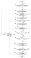
- FIG. 4 is a flow diagram showing the behavior of a processor of the vehicle control device 100.
- FIG. 13 is a diagram showing an example of a method for generating a left turn route 224 in step S4.
- FIG. 13 is a diagram showing an example of a method for generating a left turn route 224 in step S4.
- FIG. 11 is a diagram showing an example of a method for setting the assistance start range 212 in step S6.
- FIG. 13 is a diagram showing an example of vehicle operation in a situation where two possible left turns are close to each other.
- 13 is a diagram showing an example of the vehicle's operation when a stationary obstacle such as a parked vehicle is detected on an intersecting road 220.
- FIG. 13 is a diagram showing an example of the vehicle's operation when a stationary obstacle such as a parked vehicle is detected on an intersecting road 220.
- FIG. 11A and 11B are diagrams showing an example of the operation of the vehicle when a moving obstacle such as an oncoming vehicle or a pedestrian is detected during left turn assistance.
- 11A and 11B are diagrams showing an example of the operation of the vehicle when a moving obstacle such as an oncoming vehicle or a pedestrian is detected during left turn assistance.
- FIG. 11A and 11B are diagrams showing an example of the operation of the vehicle when a moving obstacle such as an oncoming vehicle or a pedestrian is detected during left turn assistance.
- FIG. 11 is a block diagram of a driving assistance travel control unit 120 according to a second embodiment.
- FIG. 11 is a diagram showing an example of an operation of a vehicle according to a second embodiment.
- FIG. 13 is a block diagram of a driving assistance travel control unit 120 according to a third embodiment.
- FIG. 1 is a schematic diagram of a vehicle 10 equipped with a driving assistance device according to the present disclosure
- FIG. 2 is a block diagram of the vehicle 10 shown in FIG. 1.
- the vehicle 10 includes, for example, a power source 11, wheels 12, a steering wheel 13, a power steering 14, a shift lever 15, an accelerator pedal 16, a brake pedal 17, a brake caliper 18, and a turn signal lever 19.
- the vehicle 10 also includes, for example, an external sensor (external recognition device) 20, a vehicle sensor 30, a navigation system 40, an HMI device 60, and a vehicle control device 100.
- an external sensor external recognition device
- vehicle sensor 30 vehicle sensor
- navigation system 40 navigation system
- HMI device 60 HMI device
- vehicle control device 100 vehicle control device
- the power source 11 is, for example, at least one of an engine and a motor, and drives multiple wheels 12 via a transmission.
- Each wheel 12 has a tire that is the ground-contacting part of the vehicle 10.
- the vehicle 10 in FIG. 1 has four wheels 12, two at the front (front wheels) and two at the rear (rear wheels).
- the steering wheel 13 allows the driver to control the steering angle of the vehicle 10 and is operated by the driver of the vehicle 10 during normal driving.
- the shift lever 15 is used by the driver to change the state of the transmission, such as "D (forward),” “N (neutral),” “P (parking),” and “R (reverse),” when the vehicle 10 is being manually driven.
- the driver increases or decreases the amount of operation (depression) of the accelerator pedal 16, thereby increasing or decreasing the driving force output from the power source 11.
- the driver When the vehicle 10 is being driven normally, the driver increases or decreases the amount of depression of the brake pedal 17, thereby increasing or decreasing the braking force generated by the brake caliper 18.
- the turn signal lever 19 is used by the driver to flash the turn signal (directional indicator (not shown)) during normal driving of the vehicle 10 to inform those around him/her of a right or left turn or lane change.
- the turn signal flashes, a signal indicating whether the left or right turn signal is flashing is sent to the vehicle control device 100 (driver assistance driving control unit 120).
- the external sensor (external environment recognition device) 20 is a sensor that acquires external information about the surroundings of the vehicle 10.
- the external sensor 20 is equipped with, for example, a monocular camera 21, a stereo camera 22, a millimeter wave radar 23, a laser radar 24, and a sonar sensor 25, and these sensors can acquire external information such as the distance and direction from the vehicle 10 to an object, the relative speed of the object to the vehicle 10, and the width of the road.
- the vehicle sensors 30 include, for example, a steering angle sensor 31, a gyro sensor 32, an acceleration sensor 33, and a speed sensor 34, and acquire driving information of the vehicle 10, including the steering angle, the angular velocities of roll, pitch, and yaw, the acceleration and deceleration in the forward and backward directions of the vehicle 10, the lateral acceleration in the lateral direction of the vehicle 10, and the speed of the vehicle 10.
- the speed sensor 34 may be, for example, a wheel speed sensor.
- the navigation system 40 includes a GNSS receiver 41 that receives radio waves from multiple positioning satellites and calculates the position information of the vehicle 10, a storage device in which map data 42 is stored, and a processor 43 that searches for a route from the current location of the vehicle 10 to a desired destination based on the position information of the vehicle 10 and the map data 42.
- the map data 42 may be downloaded from a network via a wireless communication device and then stored in the storage device.
- the navigation system 40 searches for a route to a destination set by the driver or externally, and can provide the driver with the route via the display device 61 (display, indicator, etc.) and/or provide road-level route information to the vehicle control device 100 (driver assistance driving control unit 120).
- the vehicle control device 100 is an electronic control device configured by a microcomputer equipped with, for example, a processor (e.g., a CPU), memory, a program (stored in a non-volatile memory), a timer, an input/output unit (input/output circuit), etc.
- a processor e.g., a CPU
- memory e.g., a RAM
- program stored in a non-volatile memory
- timer e.g., a timer
- input/output unit input/output circuit
- the vehicle control device 100 also includes, for example, an external environment recognition unit 110, a driving assistance driving control unit 120, a vehicle motion control unit 130, a brake control unit 140, a steering control unit 150, and a driving force control unit 160, by executing a program stored in the memory on a processor.
- Each of the sections 110, 120, 130, 140, 150, and 160 of the vehicle control device 100 may be configured by a microcomputer, or two or more may be integrated into a single microcomputer.
- each of the sections 110, 120, 130, 140, 150, and 160 of the vehicle control device 100 may represent a function of the vehicle control device 100 that is realized by, for example, executing a program by a processor. Note that these points also apply to the internal configuration of each of the sections 110, 120, 130, 140, 150, and 160.
- the HMI device 60 is composed of a display device (e.g., a monitor or touch panel) 61, a speaker 62, and an input device 63, and notifies the driver of information input from the vehicle control device 100, such as instructions, warnings, and guidance, by displaying the information as an image on the display device 61 or by issuing a warning sound or audio guidance from the speaker 62.
- a display device e.g., a monitor or touch panel
- the input device 63 is realized by the driver touching and operating a physical switch or an icon displayed on a touch panel (display device 61), and is used by the driver to give instructions for setting, starting, and ending various functions of the vehicle 10, including this function.
- the external environment recognition unit 110 integrates and selects the information acquired from the multiple sensors 21-25 that make up the external environment sensor 20 to recognize objects and road markings necessary for driving assistance of the vehicle 10, and outputs the recognition results to the driving assistance control unit 120 in an appropriate format.
- FIG. 3 is a block diagram of the driving support driving control unit 120 shown in FIG. 2.
- the driving support driving control unit 120 includes a self-position estimation unit 121, a right/left turn route generation unit 122, a driving control instruction calculation unit 123, and an HMI control unit 124.
- the self-position estimation unit 121 is a part that estimates the position of the vehicle 10, and estimates the position of the vehicle 10 based on, for example, the position data of the vehicle 10 input from the navigation system 40, the detection results of the vehicle sensor 30, and the comparison results between the detection results of the external sensor 20 and the map data 42, and outputs the estimated position of the vehicle 10 to the right/left turn route generation unit 122.
- the right/left turn route generation unit 122 receives as input the position of the vehicle 10 estimated by the self-position estimation unit 121 and the position information of the three-dimensional object and the lane markings output from the external environment recognition unit 110, and generates a route for the vehicle 10 to make a right or left turn.
- the processor of the vehicle control device 100 executes the flow of FIG. 4 at a predetermined cycle.
- FIG. 5 etc. an example of driving assistance when turning left from a road (first road) 210 on which the vehicle 10 is driving on and entering a cross road (second road) 220 that intersects the road 210 will be explained.
- this embodiment can also be applied when turning right while driving on the left side of the road, and when turning right or left while driving on the right side of the road.
- step S1 the driving support travel control unit 120 monitors whether a signal indicating that the vehicle 10 is planning to make a right or left turn (right or left turn planned signal) has been detected.
- the driving support travel control unit 120 monitors the vehicle speed signal of the speed sensor 34 and the turn signal (output according to the position of the turn signal lever 19 (right turn position, neutral position, left turn position) for example) at a predetermined time period in step S1, and outputs the right or left turn planned signal when the vehicle speed is equal to or lower than a predetermined value (first predetermined value) V1 and the turn signal (directional indicator) is activated.
- the predetermined value V1 it is preferable to select a value that can be regarded as the vehicle 10 moving slowly or stopped, and for example, a speed of 10 km/h, preferably a speed of 5 km/h, and more preferably a speed of 0 km/h can be selected.
- the right or left turn planned signal may be output when the turn signal is activated, regardless of whether the vehicle speed is V1 or not.
- step S1 If it is determined in step S1 that the vehicle speed is equal to or lower than a predetermined value V1 and the blinker is operating in the left turn direction, the driving assistance driving control unit 120 obtains the recognition result of the boundary of the intersecting road 220 (second road) from the external environment recognition unit 110 (step S2), and determines whether at least one of the boundaries of the intersecting road 220, the boundary on the right side of the traveling direction after the vehicle 10 turns left (e.g., 221 in FIG. 5) or the boundary on the left side of the same (e.g., 222 in FIG. 5), is recognized (step S3).
- a condition for a boundary to be "recognized” may also be that the length of each boundary is longer than a predetermined length (e.g., 1 m).
- the boundary of the intersecting road 220 refers to the boundary between the area of the intersecting road 220 where the vehicle 10 can pass and the area where the vehicle 10 cannot pass, and is, for example, the edge of the intersecting road 220, an obstacle on the intersecting road 220 (e.g., a vehicle or a utility pole), or a dividing line drawn on the road surface of the intersecting road 220.
- step S3 if at least one of the boundaries of the intersecting road 220, the boundary on the right side or the boundary on the left side in the traveling direction of the vehicle 10 after the left turn, is recognized, the driving assistance traveling control unit 120 generates a left turn route (right/left turn route) 224 based on the boundary information of the intersecting road 220 (step S4).
- the method of generating the left turn route 224 will be described later.
- step S3 If step S3 is not as described above (if neither the right-hand boundary nor the left-hand boundary in the direction of travel of the vehicle after a left turn can be recognized), the process returns to step S2.
- step S5 the driving assistance control unit 120 determines whether the left turn route 224 was successfully generated in step S4.
- the success or failure of the generation of the left turn route 224 can be determined, for example, by whether a route can be drawn that passes through the current position of the vehicle 10, makes one left turn, and reaches the target passing point (e.g., 223 in FIG. 5) on the intersecting road 220. In other words, if such route generation is not possible, the result is a "failure.”
- the driving assistance control unit 120 sets a predetermined range of area (hereinafter referred to as the "assistance start range") 212 (see FIG. 7, for example) based on the position of the intersecting road 220, based on the boundary information of the intersecting road 220 acquired in step S3 (step S6). It is preferable to set the assistance start range 212 on the side of the road 210 on which the vehicle is traveling, rather than the intersecting road 220.
- step S5 If route generation fails in step S5, return to step S2.
- step S6 the driving assistance travel control unit 120 determines whether the vehicle 10 is within the assistance start range 212 set in step S6 (step S7).
- An assistance start request is a general term for a signal that triggers the start of driving assistance (vehicle guidance) that automatically makes the vehicle 10 turn left along the left turn route 224 generated in step S4.
- the assistance start request can be output based on the driver's operation of the brake pedal 17, and may be output, for example, when the driver presses and then releases the brake pedal 17.
- the assistance start request is output when a temporary stop of the vehicle 10 and a subsequent brake release operation are detected, and it is determined in step S8 whether the vehicle has been temporarily stopped, and in step S9 whether a brake release operation has been performed.
- step S8 the driving assistance driving control unit 120 determines whether the vehicle 10 has stopped (temporarily stopped). Whether the vehicle 10 has stopped can be determined by monitoring the speed of the vehicle 10 and checking whether the speed becomes zero. Instead of determining whether the vehicle 10 has stopped, it may be determined whether the driver has performed a temporary stop operation on the vehicle 10. In this case, for example, if the speed of the vehicle 10 becomes zero with the brake pedal 17 depressed, it can be determined that the driver has performed a temporary stop operation on the vehicle 10. Instead of determining whether the vehicle has stopped, it may be determined that the speed of the vehicle 10 is equal to or less than a predetermined value (e.g., V1) indicating that the speed is close to zero.
- a predetermined value e.g., V1
- the driving assistance driving control unit 120 determines whether or not the driver has performed a brake release operation (i.e., released the brake pedal 17) (step S9).
- the amount of depression of the brake pedal 17 can be input from the brake control unit 140.
- the amount of depression may be detected using a brake depression force sensor that detects the depression force applied to the brake pedal 17, a brake stroke sensor that detects the amount of depression of the brake pedal 17, or a brake switch that outputs a signal according to whether or not the brake pedal 17 is being depressed.
- step S8 determines whether the vehicle 10 is stopped. If it is determined in step S8 that the vehicle 10 is not stopped, the process returns to step S7.
- step S9 If it is determined in step S9 that a brake release operation has been performed, the driving assistance travel control unit 120 starts driving assistance (vehicle guidance) to automatically perform a left turn along the left turn route 224 generated in step S4 (step S10).
- the driving control instruction calculation unit 123 calculates the target steering angle using the data on the left-turn route 224 input from the right/left turn route generation unit 122, and the steering control unit 150 generates a steering torque to the power steering 14 via the vehicle motion control unit 130 to perform automatic steering.
- the driving control instruction calculation unit 123 may calculate a target acceleration/deceleration by referring to the data on the left turn route 224 and a vehicle speed profile stored internally, and automatically adjust the vehicle speed of the vehicle 10 by causing the driving force control unit 160 to generate acceleration/deceleration torque in the power source 11 via the vehicle motion control unit 130, or by causing the brake control unit 140 to generate braking force in the brake caliper 18.
- the driving assistance control unit 120 determines whether or not the assistance end condition (described below) is met (step S11), and if the assistance end condition is met, ends the vehicle guidance and hands over driving to the driver (step S12). This prevents the driving assistance control unit 120 from continuing to intervene in driving even after entry into the intersecting road 220 is complete, and prevents the driver from feeling uncomfortable.
- the assistance end condition described below
- the support end condition in step S11 may be, for example, The travel distance of the vehicle 10 from the point where the vehicle 10 completes a turn due to driving assistance has exceeded a predetermined value; The speed of the vehicle 10 exceeds a predetermined value (a second predetermined value (but greater than V1)) V2 after the vehicle 10 completes a turn due to driving assistance; After the vehicle 10 completes the driving-assisted turn, the orientation (e.g., yaw angle) of the vehicle 10 becomes parallel to the extension direction of the intersecting road 220; The "completion of turning” may be detected, for example, by the steering angle of the vehicle 10 returning to neutral (zero).
- step S7 it is determined whether the vehicle 10 has passed through the assistance start range 212 based on the position data of the vehicle 10 and the position data of the assistance start range 212 (step S13).
- step S13 If it is determined in step S13 that the vehicle 10 has already passed the assistance start range 212, the driving assistance travel control unit 120 does not provide driving assistance according to the left turn route 224 generated in step S4.
- step S13 if it is determined in step S13 that the vehicle 10 has not yet passed through the assistance start range 212, the process returns to step S2.
- the system may monitor whether a signal indicating the cancellation of left turn assistance (assistance cancellation request) is output based on the driver's operation, and if the assistance cancellation request is detected, driving assistance may be cancelled thereafter even if an assistance start request is detected.
- the request to stop assistance may be, for example, a stop instruction by the driver via the HMI device 60, or the driver returning the turn signal lever 19 to the neutral position (i.e., the driver stopping the turn signal).
- step S4 The following provides a detailed description of how the left turn route 224 is generated in step S4 and how the assistance start range 212 is set in step S6.
- the vehicle 10 is assumed to turn left at an intersection 200 from the road 210 on which it is traveling to the road (cross road) 220 that intersects with it.
- the external sensor 20 detects the roads 210 and 220, due to the characteristics of the external sensor, there are two possible cases: when viewed from the vehicle 10 before turning left, only the left boundary 211 of the road 210 and the boundary 221 on the far side of the road 220 are detected, and the boundary 222 on the near side of the road 220 is not detected (see Figure 5); and when the boundaries 211, 221, and 222 are all detected (see Figure 6).
- the right/left turn path generation unit 122 acquires from the external sensor 20 (external environment recognition unit 110) position information of at least the forward end point 211a of the boundary 211 in the vehicle travel direction, the left end point 221a of the boundary 221, and the right end point 221b of the boundary 221.
- the range in which the boundary 221 is recognized by the external environment sensor 20 is the range from end point 221a to end point 221b.
- the right/left turn route generation unit 122 sets a target passing point (end point of the right/left turn route 224) 223 of the reference point of the vehicle 10 on the intersecting road 220 as follows:
- the lateral position of the target passing point 223 as seen from vehicle 10A after turning left may be the position of the reference point of vehicle 10 when the right end of vehicle 10A is a specified margin away from the boundary 221, as shown in FIG. 5.
- the vertical position of the target passing point 223 as seen from vehicle 10A after turning left (the position in the longitudinal direction of the intersecting road 220) may be made to coincide with the vertical position of the end point 221a as shown in FIG. 5.
- the reason for setting the lateral position of the target passing point 223 as described above is to avoid the risk of colliding with an undetected obstacle that may exist along the boundary 221, such as behind the end point 221a.
- the right/left turn route generation unit 122 After setting the target passing point 223, the right/left turn route generation unit 122 makes one left turn with the minimum turning radius of the vehicle 10, starting from the current position of the vehicle 10, and generates a left turn route 224 that passes through the target passing point 223.
- the right/left turn path generation unit 122 acquires from the external environment sensor 20 (external environment recognition unit 110) position information of at least the boundary point 211a ahead of the boundary 211 in the vehicle travel direction, the left end point 221a of the boundary 221, the right end point 221b of the boundary 221, and the left end point 222a of the boundary 222.
- boundary 222 coincides with boundary point 211a of boundary 211.
- the right/left turn route generation unit 122 sets a target passing point 223 of the reference point of the vehicle 10 on the road 220 as follows:
- the lateral position of the target passing point 223 as seen from vehicle 10A after turning left can be the center between boundary 221 and boundary 222 as shown in FIG. 6.
- the vertical position of the target passing point 223 can be the position of either the end point 221a of the boundary 221 or the end point 222a of the boundary 222, whichever is further to the right (closer to the intersection 200) as seen from the vehicle 10 before turning right, as shown in FIG. 6. That is, in the example of FIG. 6, this corresponds to the end point 222a of the boundary 222.
- the right/left turn route generation unit 122 After setting the target passing point 223, the right/left turn route generation unit 122 makes one left turn with the minimum turning radius of the vehicle 10, starting from the current position of the vehicle 10, and generates a left turn route 224 that passes through the target passing point 223.
- the route is closer to the right side of the intersecting road 220 (towards the boundary 221), which may cause the driver to feel uncomfortable if the intersecting road 220 is wide.
- the right/left turn route generation unit 122 calculates the width of the intersecting road 220 before starting to generate the left turn route 224.
- the width of the intersecting road 220 can be calculated from the difference between the vertical position of the end point 211a of the boundary 211 as seen by the vehicle 10 before making a left turn (the position in the longitudinal direction of the road 210) and the vertical position of the end point 221b of the boundary 221 as seen by the vehicle 10 before making a left turn.
- the right/left turn route generating unit 122 may generate a left turn route 224 if the result of the width calculation of the intersecting road 220 is that the width w of the intersecting road 220 is equal to or greater than a first threshold value W1 and equal to or less than a second threshold value W2 that is greater than the first threshold value, and may interrupt the generation of the left turn route 224 if the width w is any other value.
- the first threshold value W1 can be, for example, the total width of the vehicle 10 plus twice the detection error of the external sensor 20.
- the second threshold value W2 can be, for example, twice the total width of the vehicle 10.
- the assistance start range 212 is preferably positioned closer to the position of the vehicle 10 at the time the left-turn path 224 was generated than the position 213 where the vehicle 10 starts turning on the left-turn path 224 generated in step S4. This is because the left-turn assistance is to be started before the point 213 where the steering control (turning control) by the driving assistance travel control unit 120 (the processor of the vehicle control device 100) starts. Note that, as shown in FIG. 7, the leading position of the assistance start range 212 may coincide with the point (position) 213 where the vehicle 10 starts turning on the left-turn path 224 generated in step S4.
- the length of the assistance start range 212 in the vertical direction is set to be equal to or greater than the overall length of the vehicle 10, and more specifically, is preferably set to be equal to or greater than the distance an average driver travels straight from receiving various notifications to stopping the vehicle while the speed of the vehicle 10 is kept at or below a predetermined value (first predetermined value) V1 in step S1.
- This distance is longer than the distance traveled by the driver from being notified of the assistance start range 212 while driving at the predetermined vehicle speed V1 in step S1 to stopping the vehicle, thereby increasing the probability of successfully temporarily stopping the vehicle 10 within the assistance start range 212.
- One possible method for notifying the driver of the assistance start area 212 is to display it on the display device 61, superimposed on the map of the navigation system together with the left turn position.
- a parking lot 230 is located adjacent to the intersection 220 in front (at the rear in the longitudinal direction of the road 210).
- Parking lot 230 is separated from road 210 by boundary 231 and boundary 232, and entry from road 210 is possible through entrance 233 located between boundary 231 and boundary 232.
- FIG. 13 shows a situation in which vehicle 10 enters intersecting road 220 from road 210, and after the rear end of vehicle 10 passes boundary point 221b, external sensor 20 (external environment recognition unit 110) detects vehicle 227 traveling on intersecting road 220 from ahead of vehicle 10 toward vehicle 10.
- the driving assistance control unit 120 stops the vehicle 10, ends vehicle guidance, and prompts the driver to take the following action via the HMI device 60, display device 61, speaker 62, etc.
- Possible countermeasures by the driver include backing up vehicle 10, or, if road 220 is wide enough to allow vehicle 227 to pass vehicle 227, moving vehicle 10 as far to the left as possible and stopping the vehicle.
- the driving assistance device includes a vehicle control device 100 having at least one processor.
- the processor When a signal indicating that the vehicle 10 is planning to make a right or left turn (right or left turn planned signal) is detected, the processor generates a right or left turn route 224 for turning right or left from the road (first road) 210 on which the vehicle 10 is traveling to an intersecting road (second road) 220 that intersects with the road 210 based on external information acquired by the external sensor (external environment recognition device) 20, and when the vehicle 10 is located within an assistance start range 212, which is a predetermined range based on the position of the intersecting road 220, and a driver's request to start assistance is detected, driving assistance is started to automatically make a right or left turn along the right or left turn route 230.
- a right or left turn route 224 is generated, and when a driver's request to start assistance is detected while the vehicle 10 is in the assistance start range 212, the vehicle control device 100 automatically makes a right or left turn along the right or left turn route 224. That is, according to this embodiment, right or left turn assistance can be performed without additional operations for driving assistance. Also, in this embodiment, a signal indicating that the vehicle 10 is planning to make a right or left turn (right or left turn planned signal) and an assistance start request are output based on operations performed by the driver when turning right or left without driving assistance (for example, operation of a turn signal and brake pedal operation). That is, driving assistance is started in response to an operation that the driver normally performs when turning right or left, so right or left turn assistance can be achieved with natural operations for the driver without the driver having to look away from the road.
- the assistance start range 212 is set on the vehicle side of the position where the vehicle 10 starts turning on the right/left turn route 224, and right/left turn assistance is started when an assistance start request is detected in the assistance start range 212. Therefore, even if multiple locations where right/left turns are possible are close to each other, right/left turn assistance can be performed at the location intended by the driver.
- right or left turn assistance when a right or left turn is initiated by the driver on a narrow road, right or left turn assistance can be initiated by simply operating the blinker, decelerating, pausing, and restarting, which are operations that the driver normally performs when turning right or left. Furthermore, by performing operations related to the assistance start request within the assistance start range 212, right or left turn assistance can be initiated at the location intended by the driver, even when multiple locations where right or left turns are possible are close to each other.
- the configuration of this embodiment is generally the same as that of the first embodiment, but differs from the first embodiment in that a map information processing unit 125 that refers to map data 42 and recognizes possible places to turn right or left has been added to the driving assistance driving control unit 120 shown in FIG. 14.
- the vehicle control device 100 of this embodiment executes the flow of FIG. 4, which is basically the same as that of the first embodiment, at a predetermined time period when assisting in right and left turns, but the details of step S1 differ from those of the first embodiment. That is, in step S1, the driving assistance travel control unit 120 of this embodiment determines whether the vehicle 10 can take a course other than turning right or left from the road on which the vehicle is traveling to an intersecting road based on the map data 42 around the vehicle 10 or the data from the external sensor 20, and outputs a right or left turn execution signal if it is determined that the vehicle 10 cannot take a course other than turning right or left from the road on which the vehicle is traveling to an intersecting road (for example, the road on which the vehicle is traveling and the intersecting road form an L-shaped road). That is, in this embodiment, the right or left turn execution signal can be output even if the blinker is not activated.
- step S1 the map information processing unit 125 refers to the map data 42 and the position data of the vehicle 10 at a predetermined time cycle, and monitors whether there is a place in front of the vehicle 10 where it is possible to turn right or left.
- the map data 42 detects that there is a place in front of the vehicle 10 where it is not possible to go straight and a right or left turn is required, such as an L-shaped road, a right or left turn plan signal is output, and the driving assistance driving control unit 120 determines that a right or left turn will be made at that place, and performs the operations from step S2 onwards in the first embodiment.
- detection of locations where right or left turns are required may be performed using data acquired by the external sensor 20 without referring to the map data 42.
- vehicle 10 is traveling on road 300 that bends to the left in the direction of travel, and is about to enter section 300b (cross road (second road)) that bends from section 300a (the road on which vehicle 10 is traveling (first road)).
- the left boundary 301 of section 300a and the rear boundary 302 of section 300b are detected by the external sensor 20, but the front boundary 303 of section 300b is not detected.
- the right/left turn route generation unit 122 acquires from the external sensor 20 the position information of at least the forward end point 301a of the boundary 301, and the left end point 302a and the right end point 302b of the boundary 302.
- the right/left turn route generating unit 122 preferably sets a target passing point 304 of the reference point of the vehicle 10 on section 300b (intersection road) as follows.
- the horizontal position of the target passing point 304 as seen from the vehicle 10 after turning left is preferably set to the position of the reference point of the vehicle 10 when the right end of the vehicle 10 is a specified margin away from the boundary 302.
- the vertical position of the target passing point 304 is preferably set to coincide with the position of the end point 302a.
- the right/left turn route generation unit 122 generates a left turn route 305 that starts from the current position of the vehicle 10 on the section 300a, makes one left turn with the minimum turning radius of the vehicle 10, and passes through the target passing point 304.
- the right/left turn route generation unit 122 calculates the width w of the section 300b before starting the left turn route generation 305.
- the width w of section 300b can be calculated from the difference between the vertical position (position in the longitudinal direction of section 300a) of the point closest to vehicle 10 in the section between end points 302a and 302b of boundary 302, as seen from vehicle 10 before making a left turn, and the vertical position of end point 301a (position in the longitudinal direction of section 300a).
- the right/left turn route generation unit 122 If, as a result of the above, the width w of section 300b is equal to or greater than the first threshold value W1 and equal to or less than the second threshold value W2, the right/left turn route generation unit 122 generates a left turn route 305, and does not generate a left turn route in any other cases.
- FIG. 1 A third embodiment of the present invention will be described with reference to Figures 1 to 2 and 16.
- This embodiment relates to a driving support device that outputs a right/left turn execution plan signal when a vehicle 10 reaches a location where a right/left turn has been made in the past.
- the configuration of the third embodiment of the present invention is generally the same as that of the first embodiment, but differs from the first embodiment in that the driving assistance travel control unit 120 shown in FIG. 16 has a right/left turn history storage unit 126 that stores the history of right/left turns made by the vehicle 10, and a right/left turn assistance implementation determination unit 127 that determines whether right/left turn assistance is required by referring to the history of right/left turns made by the vehicle 10 and the vehicle position of the vehicle 10.
- step S1 the driving assistance travel control unit 120 of this embodiment determines whether the vehicle 10 has reached a position where it has made a right or left turn in the past based on data on positions where the vehicle has made a right or left turn in the past (right or left turn history) and the position data of the vehicle 10, and if it is determined that the vehicle has reached such a position, a right or left turn execution plan signal is output.
- the driver be able to enable/disable the function of storing the right/left turn history of the vehicle 10 via the HMI device 60.
- the right/left turn history storage unit 126 refers to the vehicle position output by the self-position estimation unit 121 and the map data 42 each time the vehicle 10 makes a right/left turn, regardless of whether right/left turn assistance is available, and stores the position where the right/left turn was made and the direction of the right/left turn.
- the right/left turn assistance implementation determination unit 127 compares the vehicle position output by the self-position estimation unit 121 with the right/left turn history stored in the right/left turn history storage unit 126.
- the right/left turn support implementation determination unit 127 decides to start support for a right or left turn according to the right/left turn direction in the corresponding right/left turn history. After this, the driving support travel control unit 120 performs the operations from step S2 onwards in the first embodiment.
- right/left turn assistance can be automatically initiated at necessary points on routes that the driver regularly uses.
- the present invention is not limited to the above-described embodiments, and includes various modifications within the scope of the gist of the present invention.
- the present invention is not limited to those having all the configurations described in the above-described embodiments, and includes those in which some of the configurations are deleted. Also, it is possible to add or replace some of the configurations of one embodiment with the configurations of another embodiment.
- each configuration of the vehicle control device 100 and the functions and execution processes of each configuration may be realized in part or in whole by hardware (for example, by designing the logic that executes each function in an integrated circuit).
- the configuration of the vehicle control device 100 may be a program (software) that is read and executed by an arithmetic processing device (for example, a CPU) to realize each function of the configuration of the vehicle control device 100.
- Information related to the program may be stored, for example, in semiconductor memory (flash memory, SSD, etc.), magnetic storage device (hard disk drive, etc.), and recording medium (magnetic disk, optical disk, etc.).
- control lines and information lines are those that are considered necessary for the explanation of the embodiment, but they do not necessarily show all the control lines and information lines related to the product. In reality, it can be considered that almost all components are interconnected.
- vehicle control device 110... external environment recognition unit, 120... driving assistance driving control unit, 121... self-position estimation unit, 122... right/left turn route generation unit, 123... driving control instruction calculation unit, 124... HMI control unit, 125... map information processing unit, 126... right/left turn history storage unit, 127... right/left turn assistance implementation determination unit, 130... vehicle motion control unit, 140... brake control unit, 150... steering control unit, 160... driving force control unit, 200... intersection, 210... road on which the vehicle 10 is traveling before turning left, 211... left boundary of the road 210, 211a... forward end point of the boundary 211, 212...
- assistance start area 213...Turning start position, 214...Assistance start area, 215...Turning start position, 220...Road intersecting road 210, 221...Boundary on the far side of road 220, 221a...Left end point of boundary 221, 221b...Right end point of boundary 221, 222...Boundary on the near side of road 220, 222a...Left end point of boundary 222, 223...Target passing point, 224...Left turn route, 225...Parked vehicle, 226...Virtual boundary of road 220 formed by parked vehicle 225, 226a...Left end point of boundary 226, 226b...Right end point of boundary 226, 227...Vehicle in motion, 228...Area through which vehicle 10 passes when turning left, 230...Parking lot, 231 ...Front boundary of parking lot 230, 231a...Front end point of boundary 231, 232...Rear boundary of parking lot
Landscapes
- Engineering & Computer Science (AREA)
- Transportation (AREA)
- Mechanical Engineering (AREA)
- Chemical & Material Sciences (AREA)
- Combustion & Propulsion (AREA)
- Physics & Mathematics (AREA)
- General Physics & Mathematics (AREA)
- Automation & Control Theory (AREA)
- Traffic Control Systems (AREA)
Priority Applications (2)
| Application Number | Priority Date | Filing Date | Title |
|---|---|---|---|
| PCT/JP2023/030918 WO2025046685A1 (ja) | 2023-08-28 | 2023-08-28 | 運転支援装置 |
| JP2025542487A JPWO2025046685A1 (https=) | 2023-08-28 | 2023-08-28 |
Applications Claiming Priority (1)
| Application Number | Priority Date | Filing Date | Title |
|---|---|---|---|
| PCT/JP2023/030918 WO2025046685A1 (ja) | 2023-08-28 | 2023-08-28 | 運転支援装置 |
Publications (1)
| Publication Number | Publication Date |
|---|---|
| WO2025046685A1 true WO2025046685A1 (ja) | 2025-03-06 |
Family
ID=94818436
Family Applications (1)
| Application Number | Title | Priority Date | Filing Date |
|---|---|---|---|
| PCT/JP2023/030918 Pending WO2025046685A1 (ja) | 2023-08-28 | 2023-08-28 | 運転支援装置 |
Country Status (2)
| Country | Link |
|---|---|
| JP (1) | JPWO2025046685A1 (https=) |
| WO (1) | WO2025046685A1 (https=) |
Citations (6)
| Publication number | Priority date | Publication date | Assignee | Title |
|---|---|---|---|---|
| JP2005215771A (ja) * | 2004-01-27 | 2005-08-11 | Nissan Motor Co Ltd | 操舵支援装置及び操舵支援プログラム |
| JP2006177905A (ja) * | 2004-12-24 | 2006-07-06 | Aisin Aw Co Ltd | ナビゲーション装置 |
| JP2008120133A (ja) * | 2006-11-08 | 2008-05-29 | Denso Corp | 車両用運転支援システム |
| WO2016042978A1 (ja) * | 2014-09-16 | 2016-03-24 | 本田技研工業株式会社 | 運転支援装置 |
| JP2018158711A (ja) * | 2017-03-21 | 2018-10-11 | 株式会社デンソー | 運転支援装置 |
| US20210394760A1 (en) * | 2019-03-07 | 2021-12-23 | Robert Bosch Gmbh | Method For Conducting A Motor Vehicle In An At Least Partially Automated Manner |
-
2023
- 2023-08-28 JP JP2025542487A patent/JPWO2025046685A1/ja active Pending
- 2023-08-28 WO PCT/JP2023/030918 patent/WO2025046685A1/ja active Pending
Patent Citations (6)
| Publication number | Priority date | Publication date | Assignee | Title |
|---|---|---|---|---|
| JP2005215771A (ja) * | 2004-01-27 | 2005-08-11 | Nissan Motor Co Ltd | 操舵支援装置及び操舵支援プログラム |
| JP2006177905A (ja) * | 2004-12-24 | 2006-07-06 | Aisin Aw Co Ltd | ナビゲーション装置 |
| JP2008120133A (ja) * | 2006-11-08 | 2008-05-29 | Denso Corp | 車両用運転支援システム |
| WO2016042978A1 (ja) * | 2014-09-16 | 2016-03-24 | 本田技研工業株式会社 | 運転支援装置 |
| JP2018158711A (ja) * | 2017-03-21 | 2018-10-11 | 株式会社デンソー | 運転支援装置 |
| US20210394760A1 (en) * | 2019-03-07 | 2021-12-23 | Robert Bosch Gmbh | Method For Conducting A Motor Vehicle In An At Least Partially Automated Manner |
Also Published As
| Publication number | Publication date |
|---|---|
| JPWO2025046685A1 (https=) | 2025-03-06 |
Similar Documents
| Publication | Publication Date | Title |
|---|---|---|
| JP7813332B2 (ja) | 運転支援装置 | |
| US10747220B2 (en) | Autonomous driving control apparatus | |
| JP6180968B2 (ja) | 車両制御装置 | |
| US9457808B2 (en) | Method for supporting a driver of a motor vehicle and device for carrying out the method | |
| JP6650904B2 (ja) | 車両制御装置 | |
| JP6607826B2 (ja) | 走行制御装置 | |
| JP6485792B2 (ja) | 運転支援制御装置 | |
| JP6460579B2 (ja) | 運転支援制御装置 | |
| WO2018211802A1 (ja) | 自動運転支援装置および自動運転支援方法 | |
| JP7219200B2 (ja) | 車両制御装置 | |
| JP2016132421A (ja) | 自動運転装置 | |
| JP7226304B2 (ja) | 車両制御装置 | |
| JP6691902B2 (ja) | 車両制御装置 | |
| CN110799403A (zh) | 车辆控制装置 | |
| JP6880222B2 (ja) | 車両制御装置 | |
| JP6600671B2 (ja) | 車両制御装置 | |
| JP6551867B2 (ja) | 運転支援制御装置 | |
| CN115335885B (zh) | 车辆控制装置、车辆用汇入辅助装置及车辆 | |
| JP7276690B2 (ja) | 車両制御装置 | |
| CN116215577A (zh) | 一种低速自动领航方法、系统、电子设备及存储介质 | |
| JP7471150B2 (ja) | 走行支援方法、及び、走行支援装置 | |
| WO2025046685A1 (ja) | 運転支援装置 | |
| US12084081B2 (en) | Driving assist device | |
| JP2024082175A (ja) | 車両制御装置 | |
| WO2025210772A1 (ja) | 運転支援方法及び運転支援装置 |
Legal Events
| Date | Code | Title | Description |
|---|---|---|---|
| 121 | Ep: the epo has been informed by wipo that ep was designated in this application |
Ref document number: 23950637 Country of ref document: EP Kind code of ref document: A1 |
|
| ENP | Entry into the national phase |
Ref document number: 2025542487 Country of ref document: JP Kind code of ref document: A |