WO2025041295A1 - 制御装置 - Google Patents
制御装置 Download PDFInfo
- Publication number
- WO2025041295A1 WO2025041295A1 PCT/JP2023/030298 JP2023030298W WO2025041295A1 WO 2025041295 A1 WO2025041295 A1 WO 2025041295A1 JP 2023030298 W JP2023030298 W JP 2023030298W WO 2025041295 A1 WO2025041295 A1 WO 2025041295A1
- Authority
- WO
- WIPO (PCT)
- Prior art keywords
- speed
- force
- robot
- control device
- force control
- Prior art date
- Legal status (The legal status is an assumption and is not a legal conclusion. Google has not performed a legal analysis and makes no representation as to the accuracy of the status listed.)
- Ceased
Links
Images


Classifications
-
- B—PERFORMING OPERATIONS; TRANSPORTING
- B25—HAND TOOLS; PORTABLE POWER-DRIVEN TOOLS; MANIPULATORS
- B25J—MANIPULATORS; CHAMBERS PROVIDED WITH MANIPULATION DEVICES
- B25J13/00—Controls for manipulators
- B25J13/08—Controls for manipulators by means of sensing devices, e.g. viewing or touching devices
- B25J13/085—Force or torque sensors
-
- B—PERFORMING OPERATIONS; TRANSPORTING
- B25—HAND TOOLS; PORTABLE POWER-DRIVEN TOOLS; MANIPULATORS
- B25J—MANIPULATORS; CHAMBERS PROVIDED WITH MANIPULATION DEVICES
- B25J11/00—Manipulators not otherwise provided for
- B25J11/005—Manipulators for mechanical processing tasks
- B25J11/0065—Polishing or grinding
-
- B—PERFORMING OPERATIONS; TRANSPORTING
- B25—HAND TOOLS; PORTABLE POWER-DRIVEN TOOLS; MANIPULATORS
- B25J—MANIPULATORS; CHAMBERS PROVIDED WITH MANIPULATION DEVICES
- B25J13/00—Controls for manipulators
- B25J13/08—Controls for manipulators by means of sensing devices, e.g. viewing or touching devices
- B25J13/088—Controls for manipulators by means of sensing devices, e.g. viewing or touching devices with position, velocity or acceleration sensors
-
- B—PERFORMING OPERATIONS; TRANSPORTING
- B25—HAND TOOLS; PORTABLE POWER-DRIVEN TOOLS; MANIPULATORS
- B25J—MANIPULATORS; CHAMBERS PROVIDED WITH MANIPULATION DEVICES
- B25J9/00—Program-controlled manipulators
- B25J9/16—Program controls
- B25J9/1628—Program controls characterised by the control loop
- B25J9/1633—Program controls characterised by the control loop compliant, force, torque control, e.g. combined with position control
-
- B—PERFORMING OPERATIONS; TRANSPORTING
- B25—HAND TOOLS; PORTABLE POWER-DRIVEN TOOLS; MANIPULATORS
- B25J—MANIPULATORS; CHAMBERS PROVIDED WITH MANIPULATION DEVICES
- B25J9/00—Program-controlled manipulators
- B25J9/16—Program controls
- B25J9/1674—Program controls characterised by safety, monitoring, diagnostic
Definitions
- This disclosure relates to a control device.
- a robot system is known that is configured to mount an end effector on the tip of a multi-joint robot and operate the multi-joint robot through force control to perform a specified task.
- Patent Documents 1 and 2 describe a robot system that can perform screw tightening tasks through force control using a screw tightening machine mounted on the robot.
- One aspect of the present disclosure is a control device that controls a robot equipped with an end effector and performing a specified task, the control device comprising: a force control unit that performs force control based on detection values from a force detector that can detect forces and moments acting on the robot; and a speed change unit that changes the speed related to the progress of the force control and the operating speed of the end effector in a coordinated manner based on the detection value of the force detector when an operation based on the force control is being performed.
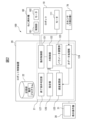
- FIG. 1 is a diagram showing a device configuration of a robot system according to an embodiment.
- FIG. 2 is a functional block diagram of the robot system.
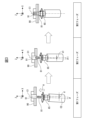
- 1A to 1C are diagrams for explaining each phase of screw tightening.
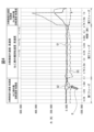
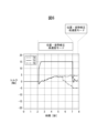
- 13 is a graph showing, as a comparative example, the transition over time of the detected value of the moment in the correction of the position and attitude in the case where the speed adjustment according to the present embodiment is not performed.
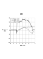
- 11 is a graph showing the time transition of the detected value of the moment when the speed of the position/attitude error is adjusted according to the present embodiment.
- FIG. 1 is a diagram showing a device configuration of a robot system according to an embodiment.
- FIG. 2 is a functional block diagram of the robot system.
- 1A to 1C are diagrams for explaining each phase of screw tightening.
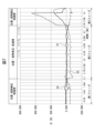
- FIG. 13 is a diagram showing the state of the force detection value during screw tightening and the speed of correction of position and attitude errors.
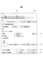
- FIG. 13 is a diagram showing an example of a setting screen for setting an end condition.
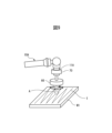
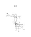
- 11A and 11B are diagrams for explaining a polishing operation by force control.
- 11A and 11B are diagrams for explaining a deburring operation by force control.
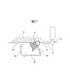
- 11A to 11C are diagrams illustrating speed adjustment according to the present embodiment when a tool comes into contact with an object such as a burr during an operation such as deburring.
- 10 is a flowchart showing a speed adjustment process in force control according to the present embodiment.
- FIG. 4 is a graph showing an example of the actual measured values detected by the force detector during screw tightening work.
- the graph in FIG. 5 shows graphs G1, G2, and G3 of the force detected by the force sensor 70 in three directions, XYZ.
- XYZ are measured values based on a coordinate system in which the axial direction (pushing direction) of the screw tightening is the Z direction, and the two directions perpendicular to it are the X and Y directions, as shown in FIG. 3.
- the forces in the X and Y directions are defined as translational forces here.
- FIG. 4 shows the approximate correspondence between the time progression of the detected values and the first to third phases.
- the case where the absolute value of the force value increases in the negative direction is also defined as the case where the force increases.
- each of the termination conditions will function as an termination condition. Therefore, a user who intends to speed up screw tightening can avoid unnecessary control by turning on the minimum necessary termination conditions. For example, in situations where there are individual differences in the length of the screws, it is important to monitor the screw tightening depth. Therefore, in such situations, it is sufficient to turn on only the setting button 312.
- the above embodiment is an example of a configuration in which a nut runner is used as the screw tightening mechanism (end effector) mounted on the robot 10, but there are also possible configurations in which an additional axis motor or a wrist axis of the robot is used as the screw tightening mechanism.
- an additional axis motor or a wrist axis of the robot is used as the screw tightening mechanism.
- a mounting plate is attached to the flange 11 of the robot 10
- the additional axis motor is fixed to this mounting plate
- a socket for screw tightening is fixed to the drive axis of this additional axis motor.
- the robot control device 20 (speed change unit 125) changes the speed related to the progress of force control and the rotation speed of the additional axis motor in coordination based on the detection value of the force detector.
- a socket is fixed to the wrist axis of the robot 10.
- the robot control device 20 (speed change unit 125) changes the speed related to the progress of force control and the rotation speed of the wrist axis motor in coordination based on the detection value of the force detector.
- the above-described embodiment is an example of a configuration for adjusting the speed when tightening a screw by force control, but the configuration for adjusting the speed of force control in the above-described embodiment can be applied to various tasks using force control (polishing, deburring, precision fitting, copying, friction stir welding, etc.). For example, consider the polishing task and deburring task shown in Figures 9 and 10, respectively.
- a polishing tool (sander or buff) 66 is rotatably attached as an end effector to the flange 11A of the wrist of the robot 10A.
- a force sensor 70 is disposed between the flange 11A and the tool 66.
- the robot control device 20 performs the polishing operation in which the polishing tool 66 moves along a trajectory T on the surface of the target object W1 while rotating it in accordance with the polishing operation program.
- the robot 10A performs force control so that the detection force in the pressing direction (the direction of arrow A in FIG. 9) becomes the target force.
- the configuration example shown in FIG. 9 is a configuration example in which the polishing tool 66 is rotated by a wrist axis motor arranged on the wrist of the robot 10A.
- the robot control device 20 (speed change unit 125) changes the speed related to the progress of force control and the rotation speed of the wrist axis motor in coordination based on the detection value of the force detector.
- the polishing tool 66 can be rotated by an additional axis motor mounted on the robot 10A.
- the robot control device 20 (speed change unit 125) changes the speed related to the progress of force control and the rotation speed of the additional axis motor in coordination based on the detection value of the force detector.
- a grinder 67 is attached to a flange 11A on the wrist of the robot 10A in a state in which it can rotate by rotating the wrist axis.
- a force sensor 70 is disposed between the flange 11A and the grinder 67.
- the robot 10A operates in accordance with a deburring program to move the grinder 67 along a trajectory T2 on the target workpiece W2 to remove burrs on the ridgeline of the target workpiece W2.
- force control is executed to press the grinder 67 in the pressing direction indicated by the arrow A1 in the figure.
- force control is executed to press the grinder 67 in the pressing direction indicated by the arrow A2 in the figure.
- the configuration example shown in FIG. 10 is a configuration example in which the grinder 67 is rotated by a wrist axis motor arranged on the wrist of the robot 10A.
- the robot control device 20 (speed change unit 125) changes the speed related to the progress of force control and the rotation speed of the wrist axis motor in coordination based on the detection value of the force detector.
- the grinder 67 can be rotated by an additional axis motor mounted on the robot 10A.
- the robot control device 20 (speed change unit 125) changes the speed related to the progress of force control and the rotation speed of the additional axis motor in coordination based on the detection value of the force detector.
- FIG. 11 is a diagram for explaining a case where the speed adjustment shown in the above embodiment is applied to the grinding operation shown in FIG. 9 and the deburring operation shown in FIG. 10. Note that FIG. 11 illustrates a case where the grinder 67 is used as the end effector in the deburring operation, but the operation is similar in the case where the tool 66 is used as the end effector in the grinding operation. FIG. 11 illustrates the behavior by force control when the grinder 67 comes into contact with a relatively large protrusion M such as a burr and a large force is detected in the deburring operation to remove burrs on the workpiece W. In this way, when the grinder 67 comes into contact with the protrusion M on the previously taught path, the robot 10 can behave in such a way as to avoid this.
- a relatively large protrusion M such as a burr
- a large force is detected in the deburring operation to remove burrs on the workpiece W.
- FIG. 11 conceptually illustrates the behavior of the grinder 67 to avoid the protrusion M.
- the avoidance path R2 to R3 may actually be a path that avoids the protrusion M toward the front of the paper in FIG. 11.
- the speed change unit 125 can set the progress speed of the force control on paths R2, R3, and R4 when the robot performs an avoidance action to low-speed mode and set the rotation speed of the grinder 67 to low-speed mode in response to detection of a large force (force/moment exceeding a threshold value) due to contact with the protrusion M. Then, when the grinder 67 returns to the taught path R5, the speed change unit 125 can set the progress speed of the force control to high-speed mode and the rotation speed of the grinder 67 to high-speed mode.
- the operation described in FIG. 11 can also be applied to the polishing operation shown in FIG. 9.
- FIG. 12 is a flowchart showing the speed adjustment process of the force control according to the above-mentioned embodiment by the robot control device 20. Note that here, the speed adjustment process when the above-mentioned first and second operation examples are applied will be explained.
- step S1 the user instructs the parameters related to force control (step S1).
- the target force, progress speed, screw tightening depth, force control gain, and other various parameters are set.
- the user sets the end conditions for the force control operation via the setting screen in Figure 8 (step S2).
- the robot controller 20 starts the force control operation by the robot 10 and monitors various parameters including the force/moment, parameters of the termination conditions, etc. (step S3).
- the robot controller 20 judges whether the detected force value (force/moment) is larger than the threshold value (step S4). If it is judged that the detected value (force/moment) is larger than the threshold value (S4: YES), the robot controller 20 (speed change unit 125) sets the progress speed of the force control to the low-speed mode, sets the rotation speed of the screw tightening machine (nut runner) 60 to the low-speed mode, and sets the speed of the position/posture correction to the high-speed mode (step S5).
- step S4 if it is determined in step S4 that the detection value (force/moment) is equal to or less than the threshold value (S4: NO), the robot control device 20 (speed change unit 125) sets the force control progress speed to high speed mode, sets the rotation speed of the screw tightening machine (nut runner) 60 to high speed mode, and sets the position/posture correction speed to low speed mode (step S6).
- first operation example by applying two types of thresholds (a first threshold and a second threshold lower than the first threshold) to the detection value of the force/moment,
- first speed mode the fastest speed mode
- second speed mode the second fastest speed mode
- third speed mode the slowest speed mode
- the grinder (67) uses an additional axis motor or a wrist axis of the robot (10).
Landscapes
- Engineering & Computer Science (AREA)
- Robotics (AREA)
- Mechanical Engineering (AREA)
- Human Computer Interaction (AREA)
- Manipulator (AREA)
Abstract
Description
第1の動作例では、ロボット制御装置20は、力検出器の検出値に基づいて、第1から第3フェーズそれぞれで力制御の進行速度およびねじ締め機60の回転速度を連携させつつ変更する。ここで、力制御による進行速度とは、例えば、目標力(ここでは、ねじ81の押付け方向(ねじ締め軸方向))へロボット10(ソケット65)を移動させる目標速度である。図3に示すように、第1フェーズは、ロボット10(ソケット65)が開始位置へ位置付けられた初期状態に対応する。したがって、ここでは、位置・姿勢誤差が比較的大きく、力検出器による検出値(力・モーメント)は大きくなる。速度変更部125は、力検出器による検出値が大きい状態であることが検出されると(例えば、検出値が所定の閾値を超えることが検出されると)、力制御による進行速度を低速度モード(第1速度モード)に設定し、ねじ締め機60の回転速度を低速度モード(第1動作速度モード)に設定する。力検出器の検出値が大きい状態であるか否かを検出するための閾値は、例えば、実験値、或いは理論値であってもよい。
・設定画面を介してユーザにより設定されている固定の進行速度、或いは、
・ねじ81の本体部の長さ、ねじ山のピッチ、ねじ締め時間、ねじの回転速度等の諸パラメータに基づいて導かれる標準値、である。
・設定画面を介して予めユーザにより設定されている回転速度、或いは、
・ねじ81の本体部の長さ、ねじ山のピッチ、ねじ締め時間等の諸パラメータから導かれる標準値、である。
(判断基準a1):並進方向の力の検出値が大きくなっている。
図4の例では、グラフG1(X方向の検出力)がマイナス方向に比較的大きく変化している(矢印Bの箇所を参照)。速度変更部125は、グラフG1(X方向の検出力)がマイナス方向に比較的大きく変化したタイミングで第1フェーズにあると判断してもよい。
(判断基準a2):ねじ締め開始直後に押付方向(Z方向)の力の検出値が大きくなっている。
ねじ締め開始時に位置誤差があり、ねじ81がねじ穴91に対して位置誤差を持つ状態では、押付方向の力の検出値も比較的大きくなると考えられる(図4におけるねじ締め開始時のグラフG3を参照)。よって、速度変更部125は、ねじ締め開始直後にZ方向の力の検出値(グラフG3)が大きくなっている場合に、第1フェーズにあると判定してもよい。
次に、ロボット制御装置20が力制御を用いた作業を実行する場合の第2の動作例について説明する。第2の動作例は、第1動作例における速度調整の動作に加えて、位置誤差・姿勢誤差の修正の速度についても速度調整を行う動作例である。以下では、位置・姿勢誤差の修正の速度をどのように調整するかについて説明する。
(手順1)はじめに、速度変更部125は、本動作例の制御を実行する一定の時間範囲を設定する。
(手順2)速度変更部125は、一定の時間範囲で力・モーメントの検出値について、所定の閾値を超える最大値を検出する(例えば、所定の閾値を超えるピーク値をとらえる)。
(手順3)速度変更部125は、検出した最大値を、位置・姿勢誤差の修正における検出値として適用する(位置・姿勢誤差の修正における検出値をこの最大値に固定する)ことで、位置・姿勢の修正速度を高速度モードに設定する。
(手順4)検出値が閾値以下である場合には、位置・姿勢の修正速度を低速度モードとする(力検出器による生の検出値を、位置・姿勢の誤差の修正における検出値としてそのまま適用する)。
(第3の動作例)
・第1フェーズでは、位置・姿勢誤差の修正を高速度モードとし、エンドエフェクタの動作速度を低速度モードとする。
・第2フェーズでは、位置・姿勢誤差の修正を低速度モードとし、エンドエフェクタの動作速度を高速度モードとする。
・第3フェーズでは、位置・姿勢誤差の修正を高速度モードとし、エンドエフェクタの動作速度を低速度モードとする。
(1)設定ボタン311は、ねじ締めの押付力が目標力に到達したことを、ねじ締めの終了条件とすることを設定するためのボタンである。
(2)設定ボタン312は、ねじ締め深さが、指定された最小値から最大値の範囲に入った場合を、ねじ締め終了条件とすることを設定するためのボタンである。
(3)設定ボタン313は、力(押付力)を終了条件とする場合に、押付力がここで指定した閾値(目標力の90%)を超えたことを終了条件とすることを設定するためのボタンである。設定ボタン311および設定ボタン313の双方がオンに設定されている場合、目標力がここで設定した判定閾値を超えた場合にねじ締めを終了する。
(4)設定ボタン314は、ロボット10(ソケット65)の速度がここで設定した判定閾値未満となったことを終了条件とすることを設定するためのボタンである。
なお、ここで示した終了条件(1)から(4)は例示であり、終了条件はこれらに限定されるものではない。例えば、モーメントを終了条件としてもよい。この場合、図8の設定画面に、終了条件としてのモーメントの判定の閾値(終了時モーメント閾値)を設定するための設定項目および設定ボタンを更に設けてもよい。
・力・モーメントの検出値が第1閾値を超える場合に第1速度モード(最も高速な速度モード)とし、
・力・モーメントの検出値が第1閾値以下で且つ第2閾値を超える場合に第2速度モード(2番目に高速な速度モード)とし、
・力・モーメントの検出値が第2閾値以下である場合に第3速度モード(最も低速な速度モード)としてもよい。
(付記1)
エンドエフェクタを搭載し所定の作業を実行するロボット(10)を制御する制御装置(20)であって、前記ロボット(10)に作用する力およびモーメントを検出可能な力検出器(70)からの検出値に基づいて力制御を実行する力制御部(122)と、前記力制御による動作が実行されているときに、前記力検出器(70)の検出値に基づいて、前記力制御の進行に係わる速度および前記エンドエフェクタの動作速度を連携させながら変更する速度変更部(125)と、を備える制御装置(20)。
(付記2)
前記力制御の進行に係わる速度は、前記力制御の目標力の方向における進行速度、または、目標軌道に沿った方向の進行速度を含む、付記1に記載の制御装置(20)。
(付記3)
前記速度変更部(125)は、
前記検出値が所定の閾値を超えたときに、前記力制御の進行速度を第1速度モードとすると共に、前記エンドエフェクタの動作速度を第1動作速度モードとし、
前記検出値が前記所定の閾値以下となったときに、前記力制御の進行速度を前記第1速度モードよりも高速の第2速度モードとすると共に、前記エンドエフェクタの動作速度を前記第1動作速度モードよりも高速の第2動作速度モードとする、付記2に記載の制御装置(20)。
(付記4)
前記力制御の進行に係わる速度は、前記力制御における位置誤差または姿勢誤差の修正の速度を含む、付記1から3のいずれか一項に記載の制御装置(20)。
(付記5)
前記速度変更部(125)は、
前記検出値が所定の閾値を超えたときに、前記位置誤差又は姿勢誤差の修正の速度を第1修正速度モードとし、
前記検出値が所定の閾値以下となったときに、前記位置誤差又は姿勢誤差の修正の速度を前記第1修正速度モードよりも低速の第2修正速度モードとする、付記4に記載の制御装置(20)。
(付記6)
前記速度変更部(125)は、一定の時間範囲内で検出される前記検出値の最大値または当該最大値に基づく値を、位置又は姿勢の誤差を修正するために力またはモーメントの検出値と基準値との偏差に力制御ゲインを乗じて前記ロボットに対する指令値を算出する場合の計算に適用することで、前記第1修正速度モードを設定する、付記5に記載の制御装置(20)。
(付記7)
前記力制御による動作を終了するための所定の複数の終了条件のうち、指定された1以上の終了条件に基づいて前記力制御による動作を終了する終了条件判定部(127)を更に備える、付記1から6のいずれか一項に記載の制御装置(20)。
(付記8)
前記複数の終了条件は、
(1)押付力が目標力に達したこと、
(2)ねじ締め深さが指定された範囲に到達したこと、
(3)押付力が目標力に対して設定された判定閾値を超えたこと、
(4)ロボットの動作速度が、指定された判定閾値未満に低下したこと、
のうちの二つ以上を含む、
付記7に記載の制御装置(20)。
(付記9)
前記所定の作業はねじ締め作業であり、前記エンドエフェクタはねじ締め機構であり、前記エンドエフェクタの動作速度は前記ねじ締め機構の回転速度である、付記1から8のいずれか一項に記載の制御装置(20)。
(付記10)
前記ねじ締め機構は、ナットランナ、付加軸モータ、又は前記ロボットの手首軸のいずれかを用いる、付記9に記載の制御装置(20)。
(付記11)
前記所定の作業は研磨作業であり、前記エンドエフェクタは研磨用の工具(66)であり、前記エンドエフェクタの動作速度は前記研磨用の工具(66)の回転速度である、付記1から7のいずれか一項に記載の制御装置(20)。
(付記12)
前記研磨用の工具(66)は、付加軸モータ、又は前記ロボット(10)の手首軸を用いる、付記11に記載の制御装置(20)。
(付記13)
前記所定の作業はバリ取り作業であり、前記エンドエフェクタはグラインダ(67)であり、前記エンドエフェクタの動作速度は前記グラインダ(67)の回転速度である、付記1から7のいずれか一項に記載の制御装置(20)。
(付記14)
前記グラインダ(67)は、付加軸モータ、又は前記ロボット(10)の手首軸を用いる、付記13に記載の制御装置(20)。
11 フランジ
20 ロボット制御装置
30 教示操作盤
51 取付板
60 ねじ締め機
65 ソケット
61 本体部
62 ヘッド部
70 力センサ
100 ロボットシステム
111 モータ
121 動作制御部
122 力制御部
123 パラメータ調整部
124 力データ処理部
125 速度変更部
126 設定部
127 終了条件判定部
161 制御部
162 モータ
Claims (14)
- エンドエフェクタを搭載し所定の作業を実行するロボットを制御する制御装置であって、
前記ロボットに作用する力およびモーメントを検出可能な力検出器からの検出値に基づいて力制御を実行する力制御部と、
前記力制御による動作が実行されているときに、前記力検出器の検出値に基づいて、前記力制御の進行に係わる速度および前記エンドエフェクタの動作速度を連携させながら変更する速度変更部と、
を備える制御装置。 - 前記力制御の進行に係わる速度は、前記力制御の目標力の方向における進行速度、または、目標軌道に沿った方向の進行速度を含む、請求項1に記載の制御装置。
- 前記速度変更部は、
前記検出値が所定の閾値を超えたときに、前記力制御の進行速度を第1速度モードとすると共に、前記エンドエフェクタの動作速度を第1動作速度モードとし、
前記検出値が前記所定の閾値以下となったときに、前記力制御の進行速度を前記第1速度モードよりも高速の第2速度モードとすると共に、前記エンドエフェクタの動作速度を前記第1動作速度モードよりも高速の第2動作速度モードとする、請求項2に記載の制御装置。 - 前記力制御の進行に係わる速度は、前記力制御における位置誤差または姿勢誤差の修正の速度を含む、請求項1から3のいずれか一項に記載の制御装置。
- 前記速度変更部は、
前記検出値が所定の閾値を超えたときに、前記位置誤差又は姿勢誤差の修正の速度を第1修正速度モードとし、
前記検出値が所定の閾値以下となったときに、前記位置誤差又は姿勢誤差の修正の速度を前記第1修正速度モードよりも低速の第2修正速度モードとする、請求項4に記載の制御装置。 - 前記速度変更部は、一定の時間範囲内で検出される前記検出値の最大値または当該最大値に基づく値を、位置又は姿勢の誤差を修正するために力またはモーメントの検出値と基準値との偏差に力制御ゲインを乗じて前記ロボットに対する指令値を算出する場合の計算に適用することで、前記第1修正速度モードを設定する、請求項5に記載の制御装置。
- 前記力制御による動作を終了するための所定の複数の終了条件のうち、指定された1以上の終了条件に基づいて前記力制御による動作を終了する終了条件判定部を更に備える、請求項1から6のいずれか一項に記載の制御装置。
- 前記複数の終了条件は、
(1)押付力が目標力に達したこと、
(2)ねじ締め深さが指定された範囲に到達したこと、
(3)押付力が目標力に対して設定された判定閾値を超えたこと、
(4)ロボットの動作速度が、指定された判定閾値未満に低下したこと、
のうちの二つ以上を含む、
請求項7に記載の制御装置。 - 前記所定の作業はねじ締め作業であり、前記エンドエフェクタはねじ締め機構であり、前記エンドエフェクタの動作速度は前記ねじ締め機構の回転速度である、請求項1から8のいずれか一項に記載の制御装置。
- 前記ねじ締め機構は、ナットランナ、付加軸モータ、又は前記ロボットの手首軸のいずれかを用いる、請求項9に記載の制御装置。
- 前記所定の作業は研磨作業であり、前記エンドエフェクタは研磨用の工具であり、前記エンドエフェクタの動作速度は前記研磨用の工具の回転速度である、請求項1から7のいずれか一項に記載の制御装置。
- 前記研磨用の工具は、付加軸モータ、又は前記ロボットの手首軸を用いる、請求項11に記載の制御装置。
- 前記所定の作業はバリ取り作業であり、前記エンドエフェクタはグラインダであり、前記エンドエフェクタの動作速度は前記グラインダの回転速度である、請求項1から7のいずれか一項に記載の制御装置。
- 前記グラインダは、付加軸モータ、又は前記ロボットの手首軸を用いる、請求項13に記載の制御装置。
Priority Applications (5)
| Application Number | Priority Date | Filing Date | Title |
|---|---|---|---|
| CN202380101160.2A CN121646522A (zh) | 2023-08-23 | 2023-08-23 | 控制装置 |
| DE112023006540.3T DE112023006540T5 (de) | 2023-08-23 | 2023-08-23 | Steuervorrichtung |
| PCT/JP2023/030298 WO2025041295A1 (ja) | 2023-08-23 | 2023-08-23 | 制御装置 |
| JP2025541241A JPWO2025041295A1 (ja) | 2023-08-23 | 2023-08-23 | |
| TW113127469A TW202508788A (zh) | 2023-08-23 | 2024-07-23 | 控制裝置 |
Applications Claiming Priority (1)
| Application Number | Priority Date | Filing Date | Title |
|---|---|---|---|
| PCT/JP2023/030298 WO2025041295A1 (ja) | 2023-08-23 | 2023-08-23 | 制御装置 |
Publications (1)
| Publication Number | Publication Date |
|---|---|
| WO2025041295A1 true WO2025041295A1 (ja) | 2025-02-27 |
Family
ID=94731706
Family Applications (1)
| Application Number | Title | Priority Date | Filing Date |
|---|---|---|---|
| PCT/JP2023/030298 Ceased WO2025041295A1 (ja) | 2023-08-23 | 2023-08-23 | 制御装置 |
Country Status (5)
| Country | Link |
|---|---|
| JP (1) | JPWO2025041295A1 (ja) |
| CN (1) | CN121646522A (ja) |
| DE (1) | DE112023006540T5 (ja) |
| TW (1) | TW202508788A (ja) |
| WO (1) | WO2025041295A1 (ja) |
Cited By (1)
| Publication number | Priority date | Publication date | Assignee | Title |
|---|---|---|---|---|
| JP7909719B1 (ja) | 2025-06-11 | 2026-08-21 | ファナック株式会社 | 制御装置 |
Citations (4)
| Publication number | Priority date | Publication date | Assignee | Title |
|---|---|---|---|---|
| JPH09155738A (ja) * | 1995-12-08 | 1997-06-17 | Meidensha Corp | ロボットの制御機構 |
| JP2011041992A (ja) * | 2009-08-19 | 2011-03-03 | Fanuc Ltd | 加工ロボットシステム |
| JP2017209754A (ja) * | 2016-05-26 | 2017-11-30 | ファナック株式会社 | 研削ロボットシステム |
| WO2022138380A1 (ja) * | 2020-12-22 | 2022-06-30 | ファナック株式会社 | ねじ締めシステム |
-
2023
- 2023-08-23 DE DE112023006540.3T patent/DE112023006540T5/de active Pending
- 2023-08-23 CN CN202380101160.2A patent/CN121646522A/zh active Pending
- 2023-08-23 JP JP2025541241A patent/JPWO2025041295A1/ja active Pending
- 2023-08-23 WO PCT/JP2023/030298 patent/WO2025041295A1/ja not_active Ceased
-
2024
- 2024-07-23 TW TW113127469A patent/TW202508788A/zh unknown
Patent Citations (4)
| Publication number | Priority date | Publication date | Assignee | Title |
|---|---|---|---|---|
| JPH09155738A (ja) * | 1995-12-08 | 1997-06-17 | Meidensha Corp | ロボットの制御機構 |
| JP2011041992A (ja) * | 2009-08-19 | 2011-03-03 | Fanuc Ltd | 加工ロボットシステム |
| JP2017209754A (ja) * | 2016-05-26 | 2017-11-30 | ファナック株式会社 | 研削ロボットシステム |
| WO2022138380A1 (ja) * | 2020-12-22 | 2022-06-30 | ファナック株式会社 | ねじ締めシステム |
Cited By (1)
| Publication number | Priority date | Publication date | Assignee | Title |
|---|---|---|---|---|
| JP7909719B1 (ja) | 2025-06-11 | 2026-08-21 | ファナック株式会社 | 制御装置 |
Also Published As
| Publication number | Publication date |
|---|---|
| CN121646522A (zh) | 2026-03-10 |
| TW202508788A (zh) | 2025-03-01 |
| DE112023006540T5 (de) | 2026-06-25 |
| JPWO2025041295A1 (ja) | 2025-02-27 |
Similar Documents
| Publication | Publication Date | Title |
|---|---|---|
| JP3681431B2 (ja) | 直交座標系上で柔らかさが調節可能なサーボ系 | |
| US10150200B2 (en) | Grinding robot system | |
| US9937594B2 (en) | Method of machining workpiece by cooperation of machine tool and robot | |
| CN102365595A (zh) | 数控装置以及该数控装置的控制方法 | |
| JP7124439B2 (ja) | 制御装置及びロボットシステム | |
| JP6693939B2 (ja) | ロボットシステム | |
| JP5011507B2 (ja) | ロボット教示システム及びロボット教示方法 | |
| CN116460862B (zh) | 主从机器人系统 | |
| JP7387999B2 (ja) | 多関節ロボット装置 | |
| US12162168B2 (en) | Method for controlling robot, robot system, and storage medium | |
| JP7525593B2 (ja) | 工作機械の制御装置、制御方法 | |
| CN121646522A (zh) | 控制装置 | |
| EP4067012B1 (en) | Method for controlling robot, robot system, and program for controlling robot | |
| WO2025004194A1 (ja) | 制御装置、ロボットシステム、および制御方法 | |
| WO2023062686A1 (ja) | ロボット制御装置及びロボットシステム | |
| WO2003068463A1 (fr) | Dispositif de commande de robot | |
| WO2024176466A1 (ja) | 制御装置及びロボットシステム | |
| JP2016093863A (ja) | ロボット制御装置 | |
| US20240189986A1 (en) | Robot system and controller | |
| JP7856591B2 (ja) | ロボットの制御方法及びシステム | |
| US12290942B2 (en) | Method for controlling robot, robot system, and storage medium | |
| TW201900301A (zh) | 銑床專用控制器驅動銑車複合機之方法 | |
| JP2025085435A (ja) | 産業用ロボット及び産業用ロボットの制御方法 | |
| WO2025027706A1 (ja) | 制御装置 | |
| JP2025085434A (ja) | 産業用ロボット |
Legal Events
| Date | Code | Title | Description |
|---|---|---|---|
| 121 | Ep: the epo has been informed by wipo that ep was designated in this application |
Ref document number: 23949753 Country of ref document: EP Kind code of ref document: A1 |
|
| ENP | Entry into the national phase |
Ref document number: 2025541241 Country of ref document: JP Kind code of ref document: A |
|
| WWE | Wipo information: entry into national phase |
Ref document number: 2025541241 Country of ref document: JP |
|
| WWE | Wipo information: entry into national phase |
Ref document number: 112023006540 Country of ref document: DE |
|
| WWP | Wipo information: published in national office |
Ref document number: 112023006540 Country of ref document: DE |