WO2025041295A1 - Dispositif de commande - Google Patents
Dispositif de commande Download PDFInfo
- Publication number
- WO2025041295A1 WO2025041295A1 PCT/JP2023/030298 JP2023030298W WO2025041295A1 WO 2025041295 A1 WO2025041295 A1 WO 2025041295A1 JP 2023030298 W JP2023030298 W JP 2023030298W WO 2025041295 A1 WO2025041295 A1 WO 2025041295A1
- Authority
- WO
- WIPO (PCT)
- Prior art keywords
- speed
- force
- robot
- control device
- force control
- Prior art date
- Legal status (The legal status is an assumption and is not a legal conclusion. Google has not performed a legal analysis and makes no representation as to the accuracy of the status listed.)
- Pending
Links
Images


Classifications
-
- B—PERFORMING OPERATIONS; TRANSPORTING
- B25—HAND TOOLS; PORTABLE POWER-DRIVEN TOOLS; MANIPULATORS
- B25J—MANIPULATORS; CHAMBERS PROVIDED WITH MANIPULATION DEVICES
- B25J13/00—Controls for manipulators
- B25J13/08—Controls for manipulators by means of sensing devices, e.g. viewing or touching devices
Definitions
- This disclosure relates to a control device.
- a robot system is known that is configured to mount an end effector on the tip of a multi-joint robot and operate the multi-joint robot through force control to perform a specified task.
- Patent Documents 1 and 2 describe a robot system that can perform screw tightening tasks through force control using a screw tightening machine mounted on the robot.
- One aspect of the present disclosure is a control device that controls a robot equipped with an end effector and performing a specified task, the control device comprising: a force control unit that performs force control based on detection values from a force detector that can detect forces and moments acting on the robot; and a speed change unit that changes the speed related to the progress of the force control and the operating speed of the end effector in a coordinated manner based on the detection value of the force detector when an operation based on the force control is being performed.
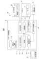
- FIG. 1 is a diagram showing a device configuration of a robot system according to an embodiment.
- FIG. 2 is a functional block diagram of the robot system.
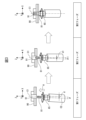
- 1A to 1C are diagrams for explaining each phase of screw tightening.
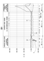
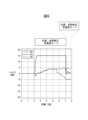
- 13 is a graph showing, as a comparative example, the transition over time of the detected value of the moment in the correction of the position and attitude in the case where the speed adjustment according to the present embodiment is not performed.
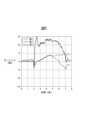
- 11 is a graph showing the time transition of the detected value of the moment when the speed of the position/attitude error is adjusted according to the present embodiment.
- FIG. 1 is a diagram showing a device configuration of a robot system according to an embodiment.
- FIG. 2 is a functional block diagram of the robot system.
- 1A to 1C are diagrams for explaining each phase of screw tightening.
- FIG. 13 is a diagram showing the state of the force detection value during screw tightening and the speed of correction of position and attitude errors.
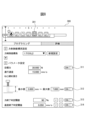
- FIG. 13 is a diagram showing an example of a setting screen for setting an end condition.
- 11A and 11B are diagrams for explaining a polishing operation by force control.
- 11A and 11B are diagrams for explaining a deburring operation by force control.
- 11A to 11C are diagrams illustrating speed adjustment according to the present embodiment when a tool comes into contact with an object such as a burr during an operation such as deburring.
- 10 is a flowchart showing a speed adjustment process in force control according to the present embodiment.
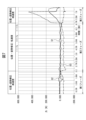
- FIG. 4 is a graph showing an example of the actual measured values detected by the force detector during screw tightening work.
- the graph in FIG. 5 shows graphs G1, G2, and G3 of the force detected by the force sensor 70 in three directions, XYZ.
- XYZ are measured values based on a coordinate system in which the axial direction (pushing direction) of the screw tightening is the Z direction, and the two directions perpendicular to it are the X and Y directions, as shown in FIG. 3.
- the forces in the X and Y directions are defined as translational forces here.
- FIG. 4 shows the approximate correspondence between the time progression of the detected values and the first to third phases.
- the case where the absolute value of the force value increases in the negative direction is also defined as the case where the force increases.
- each of the termination conditions will function as an termination condition. Therefore, a user who intends to speed up screw tightening can avoid unnecessary control by turning on the minimum necessary termination conditions. For example, in situations where there are individual differences in the length of the screws, it is important to monitor the screw tightening depth. Therefore, in such situations, it is sufficient to turn on only the setting button 312.
- the above embodiment is an example of a configuration in which a nut runner is used as the screw tightening mechanism (end effector) mounted on the robot 10, but there are also possible configurations in which an additional axis motor or a wrist axis of the robot is used as the screw tightening mechanism.
- an additional axis motor or a wrist axis of the robot is used as the screw tightening mechanism.
- a mounting plate is attached to the flange 11 of the robot 10
- the additional axis motor is fixed to this mounting plate
- a socket for screw tightening is fixed to the drive axis of this additional axis motor.
- the robot control device 20 (speed change unit 125) changes the speed related to the progress of force control and the rotation speed of the additional axis motor in coordination based on the detection value of the force detector.
- a socket is fixed to the wrist axis of the robot 10.
- the robot control device 20 (speed change unit 125) changes the speed related to the progress of force control and the rotation speed of the wrist axis motor in coordination based on the detection value of the force detector.
- the above-described embodiment is an example of a configuration for adjusting the speed when tightening a screw by force control, but the configuration for adjusting the speed of force control in the above-described embodiment can be applied to various tasks using force control (polishing, deburring, precision fitting, copying, friction stir welding, etc.). For example, consider the polishing task and deburring task shown in Figures 9 and 10, respectively.
- a polishing tool (sander or buff) 66 is rotatably attached as an end effector to the flange 11A of the wrist of the robot 10A.
- a force sensor 70 is disposed between the flange 11A and the tool 66.
- the robot control device 20 performs the polishing operation in which the polishing tool 66 moves along a trajectory T on the surface of the target object W1 while rotating it in accordance with the polishing operation program.
- the robot 10A performs force control so that the detection force in the pressing direction (the direction of arrow A in FIG. 9) becomes the target force.
- the configuration example shown in FIG. 9 is a configuration example in which the polishing tool 66 is rotated by a wrist axis motor arranged on the wrist of the robot 10A.
- the robot control device 20 (speed change unit 125) changes the speed related to the progress of force control and the rotation speed of the wrist axis motor in coordination based on the detection value of the force detector.
- the polishing tool 66 can be rotated by an additional axis motor mounted on the robot 10A.
- the robot control device 20 (speed change unit 125) changes the speed related to the progress of force control and the rotation speed of the additional axis motor in coordination based on the detection value of the force detector.
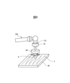
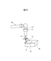
- a grinder 67 is attached to a flange 11A on the wrist of the robot 10A in a state in which it can rotate by rotating the wrist axis.
- a force sensor 70 is disposed between the flange 11A and the grinder 67.
- the robot 10A operates in accordance with a deburring program to move the grinder 67 along a trajectory T2 on the target workpiece W2 to remove burrs on the ridgeline of the target workpiece W2.
- force control is executed to press the grinder 67 in the pressing direction indicated by the arrow A1 in the figure.
- force control is executed to press the grinder 67 in the pressing direction indicated by the arrow A2 in the figure.
- the configuration example shown in FIG. 10 is a configuration example in which the grinder 67 is rotated by a wrist axis motor arranged on the wrist of the robot 10A.
- the robot control device 20 (speed change unit 125) changes the speed related to the progress of force control and the rotation speed of the wrist axis motor in coordination based on the detection value of the force detector.
- the grinder 67 can be rotated by an additional axis motor mounted on the robot 10A.
- the robot control device 20 (speed change unit 125) changes the speed related to the progress of force control and the rotation speed of the additional axis motor in coordination based on the detection value of the force detector.
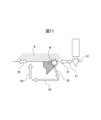
- FIG. 11 is a diagram for explaining a case where the speed adjustment shown in the above embodiment is applied to the grinding operation shown in FIG. 9 and the deburring operation shown in FIG. 10. Note that FIG. 11 illustrates a case where the grinder 67 is used as the end effector in the deburring operation, but the operation is similar in the case where the tool 66 is used as the end effector in the grinding operation. FIG. 11 illustrates the behavior by force control when the grinder 67 comes into contact with a relatively large protrusion M such as a burr and a large force is detected in the deburring operation to remove burrs on the workpiece W. In this way, when the grinder 67 comes into contact with the protrusion M on the previously taught path, the robot 10 can behave in such a way as to avoid this.
- a relatively large protrusion M such as a burr
- a large force is detected in the deburring operation to remove burrs on the workpiece W.
- FIG. 11 conceptually illustrates the behavior of the grinder 67 to avoid the protrusion M.
- the avoidance path R2 to R3 may actually be a path that avoids the protrusion M toward the front of the paper in FIG. 11.
- the speed change unit 125 can set the progress speed of the force control on paths R2, R3, and R4 when the robot performs an avoidance action to low-speed mode and set the rotation speed of the grinder 67 to low-speed mode in response to detection of a large force (force/moment exceeding a threshold value) due to contact with the protrusion M. Then, when the grinder 67 returns to the taught path R5, the speed change unit 125 can set the progress speed of the force control to high-speed mode and the rotation speed of the grinder 67 to high-speed mode.
- the operation described in FIG. 11 can also be applied to the polishing operation shown in FIG. 9.
- FIG. 12 is a flowchart showing the speed adjustment process of the force control according to the above-mentioned embodiment by the robot control device 20. Note that here, the speed adjustment process when the above-mentioned first and second operation examples are applied will be explained.
- step S1 the user instructs the parameters related to force control (step S1).
- the target force, progress speed, screw tightening depth, force control gain, and other various parameters are set.
- the user sets the end conditions for the force control operation via the setting screen in Figure 8 (step S2).
- the robot controller 20 starts the force control operation by the robot 10 and monitors various parameters including the force/moment, parameters of the termination conditions, etc. (step S3).
- the robot controller 20 judges whether the detected force value (force/moment) is larger than the threshold value (step S4). If it is judged that the detected value (force/moment) is larger than the threshold value (S4: YES), the robot controller 20 (speed change unit 125) sets the progress speed of the force control to the low-speed mode, sets the rotation speed of the screw tightening machine (nut runner) 60 to the low-speed mode, and sets the speed of the position/posture correction to the high-speed mode (step S5).
- step S4 if it is determined in step S4 that the detection value (force/moment) is equal to or less than the threshold value (S4: NO), the robot control device 20 (speed change unit 125) sets the force control progress speed to high speed mode, sets the rotation speed of the screw tightening machine (nut runner) 60 to high speed mode, and sets the position/posture correction speed to low speed mode (step S6).
- first operation example by applying two types of thresholds (a first threshold and a second threshold lower than the first threshold) to the detection value of the force/moment,
- first speed mode the fastest speed mode
- second speed mode the second fastest speed mode
- third speed mode the slowest speed mode
- the grinder (67) uses an additional axis motor or a wrist axis of the robot (10).
Landscapes
- Engineering & Computer Science (AREA)
- Human Computer Interaction (AREA)
- Robotics (AREA)
- Mechanical Engineering (AREA)
- Manipulator (AREA)
Abstract
La présente invention concerne un dispositif de commande pour commander un robot qui est équipé d'un effecteur terminal et qui effectue une tâche prédéterminée, le dispositif de commande comprenant : une unité de commande de force qui effectue une commande de force sur la base d'une valeur détectée à partir d'un détecteur de force pouvant détecter des forces et des moments agissant sur le robot ; et une unité de modification de vitesse qui modifie une vitesse impliquée dans la progression de la commande de force et une vitesse de fonctionnement de l'effecteur terminal en coordination l'une avec l'autre, sur la base de la valeur détectée provenant du détecteur de force lorsque le fonctionnement en fonction de la commande de force est effectué.
Priority Applications (3)
| Application Number | Priority Date | Filing Date | Title |
|---|---|---|---|
| PCT/JP2023/030298 WO2025041295A1 (fr) | 2023-08-23 | 2023-08-23 | Dispositif de commande |
| CN202380101160.2A CN121646522A (zh) | 2023-08-23 | 2023-08-23 | 控制装置 |
| TW113127469A TW202508788A (zh) | 2023-08-23 | 2024-07-23 | 控制裝置 |
Applications Claiming Priority (1)
| Application Number | Priority Date | Filing Date | Title |
|---|---|---|---|
| PCT/JP2023/030298 WO2025041295A1 (fr) | 2023-08-23 | 2023-08-23 | Dispositif de commande |
Publications (1)
| Publication Number | Publication Date |
|---|---|
| WO2025041295A1 true WO2025041295A1 (fr) | 2025-02-27 |
Family
ID=94731706
Family Applications (1)
| Application Number | Title | Priority Date | Filing Date |
|---|---|---|---|
| PCT/JP2023/030298 Pending WO2025041295A1 (fr) | 2023-08-23 | 2023-08-23 | Dispositif de commande |
Country Status (3)
| Country | Link |
|---|---|
| CN (1) | CN121646522A (fr) |
| TW (1) | TW202508788A (fr) |
| WO (1) | WO2025041295A1 (fr) |
Citations (4)
| Publication number | Priority date | Publication date | Assignee | Title |
|---|---|---|---|---|
| JPH09155738A (ja) * | 1995-12-08 | 1997-06-17 | Meidensha Corp | ロボットの制御機構 |
| JP2011041992A (ja) * | 2009-08-19 | 2011-03-03 | Fanuc Ltd | 加工ロボットシステム |
| JP2017209754A (ja) * | 2016-05-26 | 2017-11-30 | ファナック株式会社 | 研削ロボットシステム |
| WO2022138380A1 (fr) * | 2020-12-22 | 2022-06-30 | ファナック株式会社 | Système de fixation par vis |
-
2023
- 2023-08-23 CN CN202380101160.2A patent/CN121646522A/zh active Pending
- 2023-08-23 WO PCT/JP2023/030298 patent/WO2025041295A1/fr active Pending
-
2024
- 2024-07-23 TW TW113127469A patent/TW202508788A/zh unknown
Patent Citations (4)
| Publication number | Priority date | Publication date | Assignee | Title |
|---|---|---|---|---|
| JPH09155738A (ja) * | 1995-12-08 | 1997-06-17 | Meidensha Corp | ロボットの制御機構 |
| JP2011041992A (ja) * | 2009-08-19 | 2011-03-03 | Fanuc Ltd | 加工ロボットシステム |
| JP2017209754A (ja) * | 2016-05-26 | 2017-11-30 | ファナック株式会社 | 研削ロボットシステム |
| WO2022138380A1 (fr) * | 2020-12-22 | 2022-06-30 | ファナック株式会社 | Système de fixation par vis |
Also Published As
| Publication number | Publication date |
|---|---|
| CN121646522A (zh) | 2026-03-10 |
| TW202508788A (zh) | 2025-03-01 |
Similar Documents
| Publication | Publication Date | Title |
|---|---|---|
| JP3681431B2 (ja) | 直交座標系上で柔らかさが調節可能なサーボ系 | |
| JP6457435B2 (ja) | 研削ロボットシステム | |
| US9937594B2 (en) | Method of machining workpiece by cooperation of machine tool and robot | |
| CN102365595A (zh) | 数控装置以及该数控装置的控制方法 | |
| US11660742B2 (en) | Teaching method and robot system | |
| JP7124439B2 (ja) | 制御装置及びロボットシステム | |
| JPH074765B2 (ja) | 曲面加工装置 | |
| JP6693939B2 (ja) | ロボットシステム | |
| JP5011507B2 (ja) | ロボット教示システム及びロボット教示方法 | |
| WO2025041295A1 (fr) | Dispositif de commande | |
| CN116460862B (zh) | 主从机器人系统 | |
| JP7387999B2 (ja) | 多関節ロボット装置 | |
| JP7525593B2 (ja) | 工作機械の制御装置、制御方法 | |
| JP7658142B2 (ja) | ロボットの制御方法、ロボットシステムおよびロボット制御プログラム | |
| EP4067012B1 (fr) | Procédé de commande de robot, système de robot et programme de commande de robot | |
| WO2023062686A1 (fr) | Dispositif de commande de robot et système de robot | |
| WO2003068463A1 (fr) | Dispositif de commande de robot | |
| WO2024176466A1 (fr) | Dispositif de commande et système robotisé | |
| US20240189986A1 (en) | Robot system and controller | |
| US12290942B2 (en) | Method for controlling robot, robot system, and storage medium | |
| WO2025004194A1 (fr) | Dispositif de commande, système de robot et procédé de commande | |
| WO2025027706A1 (fr) | Dispositif de commande | |
| JPH0962335A (ja) | ソフトフローティング機能を用いた位置教示方法 | |
| JPH1177572A (ja) | ロボット制御装置 | |
| WO2026078878A1 (fr) | Dispositif d'enseignement, système robotique et procédé de création de programme d'enseignement |
Legal Events
| Date | Code | Title | Description |
|---|---|---|---|
| 121 | Ep: the epo has been informed by wipo that ep was designated in this application |
Ref document number: 23949753 Country of ref document: EP Kind code of ref document: A1 |
|
| ENP | Entry into the national phase |
Ref document number: 2025541241 Country of ref document: JP Kind code of ref document: A |
|
| WWE | Wipo information: entry into national phase |
Ref document number: 2025541241 Country of ref document: JP |