WO2025041295A1 - Control device - Google Patents
Control device Download PDFInfo
- Publication number
- WO2025041295A1 WO2025041295A1 PCT/JP2023/030298 JP2023030298W WO2025041295A1 WO 2025041295 A1 WO2025041295 A1 WO 2025041295A1 JP 2023030298 W JP2023030298 W JP 2023030298W WO 2025041295 A1 WO2025041295 A1 WO 2025041295A1
- Authority
- WO
- WIPO (PCT)
- Prior art keywords
- speed
- force
- robot
- control device
- force control
- Prior art date
- Legal status (The legal status is an assumption and is not a legal conclusion. Google has not performed a legal analysis and makes no representation as to the accuracy of the status listed.)
- Pending
Links
Images


Classifications
-
- B—PERFORMING OPERATIONS; TRANSPORTING
- B25—HAND TOOLS; PORTABLE POWER-DRIVEN TOOLS; MANIPULATORS
- B25J—MANIPULATORS; CHAMBERS PROVIDED WITH MANIPULATION DEVICES
- B25J13/00—Controls for manipulators
- B25J13/08—Controls for manipulators by means of sensing devices, e.g. viewing or touching devices
Definitions
- This disclosure relates to a control device.
- a robot system is known that is configured to mount an end effector on the tip of a multi-joint robot and operate the multi-joint robot through force control to perform a specified task.
- Patent Documents 1 and 2 describe a robot system that can perform screw tightening tasks through force control using a screw tightening machine mounted on the robot.
- One aspect of the present disclosure is a control device that controls a robot equipped with an end effector and performing a specified task, the control device comprising: a force control unit that performs force control based on detection values from a force detector that can detect forces and moments acting on the robot; and a speed change unit that changes the speed related to the progress of the force control and the operating speed of the end effector in a coordinated manner based on the detection value of the force detector when an operation based on the force control is being performed.
- FIG. 1 is a diagram showing a device configuration of a robot system according to an embodiment.
- FIG. 2 is a functional block diagram of the robot system.
- 1A to 1C are diagrams for explaining each phase of screw tightening.
- 13 is a graph showing, as a comparative example, the transition over time of the detected value of the moment in the correction of the position and attitude in the case where the speed adjustment according to the present embodiment is not performed.
- 11 is a graph showing the time transition of the detected value of the moment when the speed of the position/attitude error is adjusted according to the present embodiment.
- FIG. 1 is a diagram showing a device configuration of a robot system according to an embodiment.
- FIG. 2 is a functional block diagram of the robot system.
- 1A to 1C are diagrams for explaining each phase of screw tightening.
- FIG. 13 is a diagram showing the state of the force detection value during screw tightening and the speed of correction of position and attitude errors.
- FIG. 13 is a diagram showing an example of a setting screen for setting an end condition.
- 11A and 11B are diagrams for explaining a polishing operation by force control.
- 11A and 11B are diagrams for explaining a deburring operation by force control.
- 11A to 11C are diagrams illustrating speed adjustment according to the present embodiment when a tool comes into contact with an object such as a burr during an operation such as deburring.
- 10 is a flowchart showing a speed adjustment process in force control according to the present embodiment.
- FIG. 4 is a graph showing an example of the actual measured values detected by the force detector during screw tightening work.
- the graph in FIG. 5 shows graphs G1, G2, and G3 of the force detected by the force sensor 70 in three directions, XYZ.
- XYZ are measured values based on a coordinate system in which the axial direction (pushing direction) of the screw tightening is the Z direction, and the two directions perpendicular to it are the X and Y directions, as shown in FIG. 3.
- the forces in the X and Y directions are defined as translational forces here.
- FIG. 4 shows the approximate correspondence between the time progression of the detected values and the first to third phases.
- the case where the absolute value of the force value increases in the negative direction is also defined as the case where the force increases.
- each of the termination conditions will function as an termination condition. Therefore, a user who intends to speed up screw tightening can avoid unnecessary control by turning on the minimum necessary termination conditions. For example, in situations where there are individual differences in the length of the screws, it is important to monitor the screw tightening depth. Therefore, in such situations, it is sufficient to turn on only the setting button 312.
- the above embodiment is an example of a configuration in which a nut runner is used as the screw tightening mechanism (end effector) mounted on the robot 10, but there are also possible configurations in which an additional axis motor or a wrist axis of the robot is used as the screw tightening mechanism.
- an additional axis motor or a wrist axis of the robot is used as the screw tightening mechanism.
- a mounting plate is attached to the flange 11 of the robot 10
- the additional axis motor is fixed to this mounting plate
- a socket for screw tightening is fixed to the drive axis of this additional axis motor.
- the robot control device 20 (speed change unit 125) changes the speed related to the progress of force control and the rotation speed of the additional axis motor in coordination based on the detection value of the force detector.
- a socket is fixed to the wrist axis of the robot 10.
- the robot control device 20 (speed change unit 125) changes the speed related to the progress of force control and the rotation speed of the wrist axis motor in coordination based on the detection value of the force detector.
- the above-described embodiment is an example of a configuration for adjusting the speed when tightening a screw by force control, but the configuration for adjusting the speed of force control in the above-described embodiment can be applied to various tasks using force control (polishing, deburring, precision fitting, copying, friction stir welding, etc.). For example, consider the polishing task and deburring task shown in Figures 9 and 10, respectively.
- a polishing tool (sander or buff) 66 is rotatably attached as an end effector to the flange 11A of the wrist of the robot 10A.
- a force sensor 70 is disposed between the flange 11A and the tool 66.
- the robot control device 20 performs the polishing operation in which the polishing tool 66 moves along a trajectory T on the surface of the target object W1 while rotating it in accordance with the polishing operation program.
- the robot 10A performs force control so that the detection force in the pressing direction (the direction of arrow A in FIG. 9) becomes the target force.
- the configuration example shown in FIG. 9 is a configuration example in which the polishing tool 66 is rotated by a wrist axis motor arranged on the wrist of the robot 10A.
- the robot control device 20 (speed change unit 125) changes the speed related to the progress of force control and the rotation speed of the wrist axis motor in coordination based on the detection value of the force detector.
- the polishing tool 66 can be rotated by an additional axis motor mounted on the robot 10A.
- the robot control device 20 (speed change unit 125) changes the speed related to the progress of force control and the rotation speed of the additional axis motor in coordination based on the detection value of the force detector.
- a grinder 67 is attached to a flange 11A on the wrist of the robot 10A in a state in which it can rotate by rotating the wrist axis.
- a force sensor 70 is disposed between the flange 11A and the grinder 67.
- the robot 10A operates in accordance with a deburring program to move the grinder 67 along a trajectory T2 on the target workpiece W2 to remove burrs on the ridgeline of the target workpiece W2.
- force control is executed to press the grinder 67 in the pressing direction indicated by the arrow A1 in the figure.
- force control is executed to press the grinder 67 in the pressing direction indicated by the arrow A2 in the figure.
- the configuration example shown in FIG. 10 is a configuration example in which the grinder 67 is rotated by a wrist axis motor arranged on the wrist of the robot 10A.
- the robot control device 20 (speed change unit 125) changes the speed related to the progress of force control and the rotation speed of the wrist axis motor in coordination based on the detection value of the force detector.
- the grinder 67 can be rotated by an additional axis motor mounted on the robot 10A.
- the robot control device 20 (speed change unit 125) changes the speed related to the progress of force control and the rotation speed of the additional axis motor in coordination based on the detection value of the force detector.
- FIG. 11 is a diagram for explaining a case where the speed adjustment shown in the above embodiment is applied to the grinding operation shown in FIG. 9 and the deburring operation shown in FIG. 10. Note that FIG. 11 illustrates a case where the grinder 67 is used as the end effector in the deburring operation, but the operation is similar in the case where the tool 66 is used as the end effector in the grinding operation. FIG. 11 illustrates the behavior by force control when the grinder 67 comes into contact with a relatively large protrusion M such as a burr and a large force is detected in the deburring operation to remove burrs on the workpiece W. In this way, when the grinder 67 comes into contact with the protrusion M on the previously taught path, the robot 10 can behave in such a way as to avoid this.
- a relatively large protrusion M such as a burr
- a large force is detected in the deburring operation to remove burrs on the workpiece W.
- FIG. 11 conceptually illustrates the behavior of the grinder 67 to avoid the protrusion M.
- the avoidance path R2 to R3 may actually be a path that avoids the protrusion M toward the front of the paper in FIG. 11.
- the speed change unit 125 can set the progress speed of the force control on paths R2, R3, and R4 when the robot performs an avoidance action to low-speed mode and set the rotation speed of the grinder 67 to low-speed mode in response to detection of a large force (force/moment exceeding a threshold value) due to contact with the protrusion M. Then, when the grinder 67 returns to the taught path R5, the speed change unit 125 can set the progress speed of the force control to high-speed mode and the rotation speed of the grinder 67 to high-speed mode.
- the operation described in FIG. 11 can also be applied to the polishing operation shown in FIG. 9.
- FIG. 12 is a flowchart showing the speed adjustment process of the force control according to the above-mentioned embodiment by the robot control device 20. Note that here, the speed adjustment process when the above-mentioned first and second operation examples are applied will be explained.
- step S1 the user instructs the parameters related to force control (step S1).
- the target force, progress speed, screw tightening depth, force control gain, and other various parameters are set.
- the user sets the end conditions for the force control operation via the setting screen in Figure 8 (step S2).
- the robot controller 20 starts the force control operation by the robot 10 and monitors various parameters including the force/moment, parameters of the termination conditions, etc. (step S3).
- the robot controller 20 judges whether the detected force value (force/moment) is larger than the threshold value (step S4). If it is judged that the detected value (force/moment) is larger than the threshold value (S4: YES), the robot controller 20 (speed change unit 125) sets the progress speed of the force control to the low-speed mode, sets the rotation speed of the screw tightening machine (nut runner) 60 to the low-speed mode, and sets the speed of the position/posture correction to the high-speed mode (step S5).
- step S4 if it is determined in step S4 that the detection value (force/moment) is equal to or less than the threshold value (S4: NO), the robot control device 20 (speed change unit 125) sets the force control progress speed to high speed mode, sets the rotation speed of the screw tightening machine (nut runner) 60 to high speed mode, and sets the position/posture correction speed to low speed mode (step S6).
- first operation example by applying two types of thresholds (a first threshold and a second threshold lower than the first threshold) to the detection value of the force/moment,
- first speed mode the fastest speed mode
- second speed mode the second fastest speed mode
- third speed mode the slowest speed mode
- the grinder (67) uses an additional axis motor or a wrist axis of the robot (10).
Landscapes
- Engineering & Computer Science (AREA)
- Human Computer Interaction (AREA)
- Robotics (AREA)
- Mechanical Engineering (AREA)
- Manipulator (AREA)
Abstract
Description
本開示は、制御装置に関する。 This disclosure relates to a control device.
多関節ロボットの先端部にエンドエフェクタを搭載し、多関節ロボットを力制御により動作させて所定の作業を行うように構成されたロボットシステムが知られている。例えば、特許文献1および特許文献2は、ロボットに搭載したねじ締め機を用い力制御によるねじ締め作業を実行可能なロボットシステムを記載している。
A robot system is known that is configured to mount an end effector on the tip of a multi-joint robot and operate the multi-joint robot through force control to perform a specified task. For example,
エンドエフェクタを搭載したロボットに力制御による作業を実行させる場合、力制御の諸パラメータは、ユーザが事前に調整した固定のパラメータが用いられるのが一般的である。しかしながら、力制御による作業には、力制御の進行に係わる速度を、事前に調整した固定のパラメータで実行する場合よりも高速に実行できる部分が存在する場合がある。力制御の動作を的確に実行しつつ作業のサイクルタイムを短縮可能な技術が望まれている。 When a robot equipped with an end effector is made to perform a task using force control, the force control parameters are generally fixed and adjusted in advance by the user. However, there are cases where the speed of the force control progress can be faster in a task using force control than when the task is performed using fixed parameters that have been adjusted in advance. There is a demand for technology that can reduce the cycle time of a task while accurately performing force control operations.
本開示の一態様は、エンドエフェクタを搭載し所定の作業を実行するロボットを制御する制御装置であって、前記ロボットに作用する力およびモーメントを検出可能な力検出器からの検出値に基づいて力制御を実行する力制御部と、前記力制御による動作が実行されているときに、前記力検出器の検出値に基づいて、前記力制御の進行に係わる速度および前記エンドエフェクタの動作速度を連携させながら変更する速度変更部と、を備える制御装置である。 One aspect of the present disclosure is a control device that controls a robot equipped with an end effector and performing a specified task, the control device comprising: a force control unit that performs force control based on detection values from a force detector that can detect forces and moments acting on the robot; and a speed change unit that changes the speed related to the progress of the force control and the operating speed of the end effector in a coordinated manner based on the detection value of the force detector when an operation based on the force control is being performed.
添付図面に示される本発明の典型的な実施形態の詳細な説明から、本発明のこれらの目的、特徴および利点ならびに他の目的、特徴および利点がさらに明確になるであろう。 These and other objects, features and advantages of the present invention will become more apparent from the detailed description of exemplary embodiments of the present invention illustrated in the accompanying drawings.
次に、本開示の実施形態について図面を参照して説明する。参照する図面において、同様の構成部分または機能部分には同様の参照符号が付けられている。理解を容易にするために、これらの図面は縮尺を適宜変更している。また、図面に示される形態は本発明を実施するための一つの例であり、本発明は図示された形態に限定されるものではない。 Next, an embodiment of the present disclosure will be described with reference to the drawings. In the drawings, similar components or functional parts are given similar reference symbols. The scale of these drawings has been appropriately changed to facilitate understanding. Furthermore, the form shown in the drawings is one example for implementing the present invention, and the present invention is not limited to the form shown.
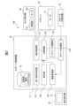
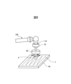
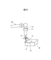
図1は1実施形態に係るロボットシステム100の機器構成を示す図である。図1に示すように、ロボットシステム100は、ロボット10と、ロボット10を制御するロボット制御装置20と、ロボット制御装置20に接続された教示操作盤30とを備える。ロボット10の手首部のフランジ11には、取付板51を介してエンドエフェクタとしてのねじ締め機60が取り付けられている。手首部のフランジ11と取付板51との間には、外力を検出する力センサ(力検出器)70が取り付けられている。上記構成において、ロボットシステム100は、ロボット10によりねじ締め機60を所望の位置・姿勢に設定し、力センサ70により検出された検出値に基づいてロボット10に力制御によるねじ締め作業を実行させることができる。以下で詳細に説明するように、ロボット制御装置20は、力検出器の検出値に基づいて、力制御の進行に係わる速度とエンドエフェクタの動作速度とを連携させながら変更することで、力制御による作業のサイクルタイムを短縮することができる。
1 is a diagram showing the equipment configuration of a
ロボット10は、例示として、6軸の垂直多関節ロボットであるものとする。なお、ロボット10として、水平多関節ロボット、パラレルリンク型ロボット、双腕ロボット等、作業対象に応じて様々なタイプのロボットが用いられても良い。図1では、ロボット10にエンドエフェクタとしてねじ締め機60が搭載されている構成例を示すが、ロボット10には、作業用途に応じて様々なタイプのエンドエフェクタを取り付けることができる。
As an example, the
ロボット制御装置20は、動作プログラム或いは教示操作盤30からの指令に従ってロボット10の動作を制御する。ロボット制御装置20は、プロセッサ21(図2参照)、メモリ(ROM、RAM、不揮発性メモリ等)、記憶装置、操作部、入出力インタフェース、ネットワークインタフェース等を有する一般的なコンピュータとしてのハードウェア構成を有していても良い。
The
教示操作盤30は、ロボット10の教示や各種設定を行うための操作端末として用いられる。教示操作盤30として、タブレット端末等により構成された教示装置を用いても良い。教示操作盤30は、プロセッサ、メモリ(ROM、RAM、不揮発性メモリ等)、記憶装置、操作部、表示部31(図2参照)、入出力インタフェース、ネットワークインタフェース等を有する一般的なコンピュータとしてのハードウェア構成を有していても良い。
The
ねじ締め機60は、一例として、アングルタイプのねじ締め機(ナットランナー)である。ねじ締め機60は、制御部161及びモータ162(図2参照)を内部に含む本体部61と、本体部61の先端部に連結されたヘッド部62とを備える。ヘッド部62は、工具としてのソケット65を保持する。ソケット65には、ねじ81が保持される。ねじ締め機60は、ロボット制御装置20に接続され、ロボット制御装置20からの指令により、ねじ81を対象物のねじ穴に締付け固定する。
The
ねじ締め機60は、取付板51の一方の側に取り付けられ、また、取付板51の他方の側はロボット10のフランジ11に取り付けられている。この構成おいて、ロボット10によりねじ締め機60を所望の位置・姿勢に設定して対象物に対するねじ締め作業を実行することができる。
The
力センサ70は、例えば、互いに直交するX,Y,Z各軸方向に作用する力、及び各軸周りのモーメントを検出する6軸力センサである。なお、本実施形態では、ロボット10に作用する外力を力センサ70により検出する構成としているが、力センサに代えてロボットの各軸に設けたトルクセンサの検出値により外力を検出する構成としても良い。
The
図2は、ロボットシステム100の機能ブロック図である。図2に示すように、ロボット制御装置20は、動作制御部121と、力制御部122と、パラメータ調整部123と、力データ処理部124と、速度変更部125と、設定部126と、終了条件判定部127とを備える。これらの機能ブロックは、ロボット制御装置20のプロセッサ21がソフトウェアを実行することで実現される機能要素であっても良い。
FIG. 2 is a functional block diagram of the
ロボット制御装置20は、記憶部22を備える。記憶部22は、例えば、不揮発性メモリ或いはハードディスク装置等からなる記憶装置である。記憶部22には、ロボット10を制御する動作プログラム、力制御パラメータや動作パラメータを含む各種設定情報等が格納される。
The
動作制御部121は、動作プログラムにしたがって、或いは教示操作盤30からの指令に従ってロボット10の動作を制御する。ロボット制御装置20は、動作制御部121が生成する各軸に対する指令に従って各軸のモータ111に対するサーボ制御を実行するサーボ制御部(不図示)を備えている。
The
力データ処理部124は、力センサ70の検出値に基づいて、ロボット10の所定の部位(ねじ締め機60等)に作用する外力(力及びモーメント)を算出する機能を提供する。力センサ70の位置および姿勢は、ロボット10の手首部先端の座標系の位置および姿勢と、手首部先端に対する力センサ70の相対位置情報により算出することができる。力データ処理部124は、力センサ70の位置、姿勢、及び検出値に基づいて、ロボット10に予め設定された任意の座標系における力やモーメントの大きさ、及び、力やモーメントの方向を算出することができる。
The force
力制御部122は、力データ処理部124が算出した力情報、及び所定の力制御パラメータに基づいて力制御を実行する機能を司る。動作制御部121は、力制御部122による指令の下で、ロボット10に力制御による動作を実行させる機能を有する。
The
パラメータ調整部123は、例えば、ロボット10に力制御による動作(ねじ締め作業、精密篏合作業等における位置・姿勢の修正動作)を繰り返し実行させることで力制御パラメータ(押付力、力制御ゲイン(押付方向、位置誤差・姿勢誤差方向)等)を調整する機能を提供する。ユーザは、事前にパラメータ調整部123の機能を用いて取得した力制御パラメータを、動作プログラムの力制御パラメータとして適用することができる。
The
速度変更部125は、力制御による動作が実行されているときに、力検出器の検出値に基づいて、力制御の進行に係わる速度およびエンドエフェクタの動作速度を連携させながら変更する機能を提供する。
The
設定部126は、動作プログラムに関する機能設定を行うため機能を提供する。設定部126による機能には、ロボットの各種の機能に対応するアイコンを用いたプログラミングにおいて、各アイコンに対する詳細設定を行うためのユーザインタフェースを提供する機能が含まれる。
The
終了条件判定部127は、所定の終了判定条件に基づいて力制御による作業が終了しているか否かを判定する機能を有する。
The end
ねじ締め機60は、ソケット65を回転させるためのモータ162と、モータ162を駆動制御する制御部161とを備える。制御部161は、動作制御部121からの指令(動作パラメータの指定等を含む)に従ってモータ162の駆動制御を行う。制御部161は、例えば、CPU、メモリ(ROM、RAM、不揮発性メモリ等)等が組み込まれたマイクロコンピュータチップにより構成されていても良い。
The
以下、ロボット制御装置20による制御の下で実行される力制御を用いたねじ締め作業について説明する。
The following describes the screw tightening operation using force control, which is performed under the control of the
本実施形態によるねじ締め動作の理解のため、ここで、一般的な力制御によるねじ締め動作について説明する。力制御を用いたねじ締め動作では、ロボット10(ソケット65)は、はじめに、教示されたねじ締め開始位置に位置付けられ、位置誤差・姿勢誤差を修正しながらねじ81をねじ穴に挿入させてねじ81をねじ穴に締め付け固定する。以上のような力制御を用いたねじ締め動作では、一般に、押付力、ねじ締め機の回転速度、力制御ゲイン、力制御の進行速度等のパラメータは固定の値が用いられる。しかしながら、力制御を用いた作業には、例えば、力制御の進行速度をその固定の速度よりも高速に実行できる部分が存在する場合がある。他方、サイクルタイムを短縮するために、作業を分割してプログラムを構成し、それぞれの分割部分ごとに進行速度等のパラメータ設定を行う形で動作プログラムを作成するには多くの手間を要することとなる。このような状況に鑑み、本実施形態に係るロボット制御装置20は、力制御による作業が実行されているときに、力検出器の検出値に基づいて、力制御の進行に係わる速度とエンドエフェクタの動作速度とを連携させながら自動的に変更する機能を提供する。
In order to understand the screw tightening operation according to this embodiment, a general screw tightening operation using force control will be described here. In a screw tightening operation using force control, the robot 10 (socket 65) is first positioned at the instructed screw tightening start position, and the
以下では、例示として、ロボット制御装置20が力制御によるねじ締め作業において、力制御の進行に係わる速度とエンドエフェクタの動作速度とを連携させながら変更する2つの動作例について説明する。なお、以下で説明する2つの動作例では、ロボット制御装置20は、力制御を用いたねじ締め作業を、力検出器の検出値の大きさの推移の観点で、図3に示すような3つのフェーズに分けて速度調整を行う制御を実現する。
Below, two operation examples will be described as examples in which the
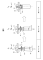
第1フェーズは、図3中左側に示すように、ねじ締め開始位置に位置付けられたロボット10(ソケット65)の位置誤差および姿勢誤差(位置・姿勢誤差)を、力制御を使って修正するフェーズである。ここで、位置誤差とは、図3中の第1フェーズにおいて距離dとして示すように、ねじ穴91の中心線C1に対するねじ81の先端の中心の位置ずれとして定義することができる。姿勢誤差とは、図3中の第1フェーズにおいて角度θとして示すようにねじ穴91の中心線C1に対するねじ81(ソケット65)の中心軸線C2の傾きとして定義することができる。第1フェーズでは、力制御により位置誤差d、姿勢誤差θを修正する動作が行われる。
The first phase, as shown on the left side of Figure 3, is a phase in which force control is used to correct the position error and attitude error (position/attitude error) of the robot 10 (socket 65) positioned at the screw tightening start position. Here, the position error can be defined as the positional deviation of the center of the tip of the
第2フェーズは、図3中中央に示すように、位置誤差d1・姿勢誤差θ1が収束に近い状態となり力制御を使ってねじ締め軸方向にねじ81を進行させてねじ締めを行い始めるフェーズである。第3フェーズは、図3中右側に示すように力制御を使ってねじ81を軸方向に進行させ、ねじ81をねじ穴91に締め付け固定するフェーズである。
The second phase, as shown in the center of Figure 3, is when the position error d1 and attitude error θ1 are close to convergence and force control is used to advance the
(第1の動作例)
第1の動作例では、ロボット制御装置20は、力検出器の検出値に基づいて、第1から第3フェーズそれぞれで力制御の進行速度およびねじ締め機60の回転速度を連携させつつ変更する。ここで、力制御による進行速度とは、例えば、目標力(ここでは、ねじ81の押付け方向(ねじ締め軸方向))へロボット10(ソケット65)を移動させる目標速度である。図3に示すように、第1フェーズは、ロボット10(ソケット65)が開始位置へ位置付けられた初期状態に対応する。したがって、ここでは、位置・姿勢誤差が比較的大きく、力検出器による検出値(力・モーメント)は大きくなる。速度変更部125は、力検出器による検出値が大きい状態であることが検出されると(例えば、検出値が所定の閾値を超えることが検出されると)、力制御による進行速度を低速度モード(第1速度モード)に設定し、ねじ締め機60の回転速度を低速度モード(第1動作速度モード)に設定する。力検出器の検出値が大きい状態であるか否かを検出するための閾値は、例えば、実験値、或いは理論値であってもよい。
(First operation example)
In the first operation example, the
ここで力制御の進行速度について、低速度モードとは、基準となる進行速度以下の速度である場合を指す。基準となる進行速度(以下、基準進行速度とも称する)は、例えば、
・設定画面を介してユーザにより設定されている固定の進行速度、或いは、
・ねじ81の本体部の長さ、ねじ山のピッチ、ねじ締め時間、ねじの回転速度等の諸パラメータに基づいて導かれる標準値、である。
Regarding the progress speed of the force control, the low speed mode refers to a speed equal to or lower than a reference progress speed. The reference progress speed (hereinafter also referred to as the reference progress speed) is, for example,
A fixed progression speed set by the user via a settings screen, or
A standard value derived based on various parameters such as the length of the body of the
ねじ締め機60の動作速度について低速度モードとは、基準となる回転速度以下となる回転速度である場合を指す。基準となる回転速度(以下、基準回転速度とも称する)は、例えば、
・設定画面を介して予めユーザにより設定されている回転速度、或いは、
・ねじ81の本体部の長さ、ねじ山のピッチ、ねじ締め時間等の諸パラメータから導かれる標準値、である。
The low-speed mode of the
The rotation speed is preset by the user via a setting screen, or
A standard value derived from various parameters such as the length of the body of the
このように、ロボット制御装置20は、ロボット10の位置・姿勢誤差の修正が行われるときの力制御の進行速度を低速度モードとすることで位置・姿勢の修正が適切に行われ、ねじ81がねじ穴91に確実に挿入されるようにする。また、このとき、ロボット制御装置20は、ねじ締め機60の回転速度も連携して低速度モードに設定することで、ねじ81を保護すると共に位置・姿勢の修正が的確に行われるようにする。
In this way, the
第2フェーズでは、第1フェーズでの位置・姿勢誤差の修正により位置・姿勢誤差は収束に近い状態となっているため力検出器による検出値は小さくなる。具体的には、位置・姿勢の修正に係わる並進方向の力(図中XY方向の力)およびモーメント(WPR)の検出値は小さくなる。したがって、速度変更部125は、力検出器の検出値(並進力、モーメント)が小さくなると(例えば、検出値が所定の閾値以下となることが検出されると)、力制御の進行速度を高速度モード(第2速度モード)とし、ねじ締め機60の回転速度を高速度モード(第2動作速度モード)に設定する。ここで進行速度について、高速度モードとは、例えば、上記基準進行速度よりも高速の進行速度である。ねじ締め機60の動作速度について高速度モードとは、例えば、上記基準回転速度よりも高速の回転速度である。
In the second phase, the position and orientation errors are close to convergence due to the correction of the position and orientation errors in the first phase, so the detection value of the force detector becomes small. Specifically, the detection value of the translational force (force in the XY direction in the figure) and moment (WPR) related to the correction of the position and orientation becomes small. Therefore, when the detection value (translational force, moment) of the force detector becomes small (for example, when it is detected that the detection value is below a predetermined threshold value), the
第2フェーズでは、位置・姿勢誤差は収束に近い状態であり、また、ねじ81はねじ穴91に締め付けられ始めた段階にある。したがって、第2フェーズは、力制御の進行速度およびねじ締め機60の回転速度を高めることが可能な状態である。よって、第2フェーズにおいて力制御の進行速度およびねじ締め機60の回転速度を共に速めることで、ねじ締め全体のサイクルタイムを短縮することが可能となる。
In the second phase, the position and orientation errors are close to convergence, and the
第3フェーズでは、ねじ81がねじ穴91中で回転しながら締め付けられる状態であるため、力検出器の検出値は大きな値となる。したがって、速度変更部125は、力検出器の検出値(力・モーメント)が大きくなると(例えば、検出値が所定の閾値を超えることが検出されると)、力制御の進行速度を低速度モードに設定し、ねじ締め機60の回転速度を低速度モードに設定する。
In the third phase, the
このように、第3フェーズでは、ロボット制御装置20は、ねじ81のねじ穴への締め付けが適正に行われるように、力制御の進行速度を比較的低い速度とし、ねじ締め機60の回転速度を比較的低い速度とする。これにより、ねじ81をねじ穴に締め付ける過程で姿勢誤差が大きくなることを回避し安定したねじ締めを実行することができる。
In this way, in the third phase, the
以上のような第1の動作例による速度制御により、力制御を用いた作業において本来的に進行速度を高めることができる部分の進行速度を高めることが可能となり、それにより作業全体にかかるサイクルタイムを短縮することが可能となる。 By controlling the speed using the first operation example described above, it becomes possible to increase the progress speed of parts of the work that can be inherently increased in speed using force control, thereby shortening the cycle time for the entire work.
第1の動作例は、力検出器の検出値に応じて、力制御の進行速度を第1速度とし、ねじ締め機60の回転速度を第1回転速度とする第1速度モードと、力制御の進行速度を第1速度よりも低速の第2速度とし、ねじ締め機60の回転速度を第1回転速度よりも低速の第2回転速度とする第2速度モードとを切り替え可能とする動作例であると言うことができる。このような構成は、力制御を用いた作業において本来的に進行速度を高めることができる部分の進行速度を高め、それにより作業全体にかかるサイクルタイムを短縮することを可能とする。
The first operation example can be said to be an operation example that can switch between a first speed mode in which the progress speed of force control is a first speed and the rotation speed of the
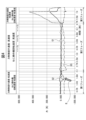
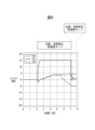
図4は、ねじ締め作業の実行中に力検出器により検出された検出値の実測値の例を示すグラフである。図5のグラフは、力センサ70によるXYZ3つの方向についての力の検出値のグラフG1、G2、G3を示す。ここで、XYZは、図3に示したような、ねじ締めの軸方向(押付方向)をZ方向とし、それに直交する2方向をX,Y方向とする座標系を基準とする測定値である。なお、ここでは、XとY方向の力を並進力と定義する。なお、図4には、理解の便宜のため、検出値の時間推移と第1から第3フェーズとのおおよその対応を示している。図4では、力の値の絶対値がマイナス方向に大きくなる場合についても、力が大きくなる場合と定義する。
FIG. 4 is a graph showing an example of the actual measured values detected by the force detector during screw tightening work. The graph in FIG. 5 shows graphs G1, G2, and G3 of the force detected by the
速度変更部125は、位置・姿勢誤差が比較的大きくなっている第1フェーズを、力検出器の検出値に基づく以下のような判断基準(a1)、(a2)の少なくとも一つにより判断してもよい。
(判断基準a1):並進方向の力の検出値が大きくなっている。
図4の例では、グラフG1(X方向の検出力)がマイナス方向に比較的大きく変化している(矢印Bの箇所を参照)。速度変更部125は、グラフG1(X方向の検出力)がマイナス方向に比較的大きく変化したタイミングで第1フェーズにあると判断してもよい。
(判断基準a2):ねじ締め開始直後に押付方向(Z方向)の力の検出値が大きくなっている。
ねじ締め開始時に位置誤差があり、ねじ81がねじ穴91に対して位置誤差を持つ状態では、押付方向の力の検出値も比較的大きくなると考えられる(図4におけるねじ締め開始時のグラフG3を参照)。よって、速度変更部125は、ねじ締め開始直後にZ方向の力の検出値(グラフG3)が大きくなっている場合に、第1フェーズにあると判定してもよい。
The
(Criterion a1): The detected value of the force in the translational direction is increasing.
4, the graph G1 (detection power in the X direction) changes relatively significantly in the negative direction (see the portion indicated by the arrow B). The
(Judgment criterion a2): Immediately after starting to tighten the screw, the detected force value in the pressing direction (Z direction) becomes large.
When there is a position error at the start of screw tightening, and the
第1フェーズにあると判定すると、速度変更部125は、上述したように力制御の進行速度を低速度モードに設定し、ねじ締め機60の回転速度を低速度モードに設定する。
If it is determined that the first phase is in progress, the
第2フェーズに入ると、位置・姿勢誤差が小さくなることに伴い、X方向およびY方向の力(並進力)或いはモーメントの検出値は小さくなる。ここでは、速度変更部125は、並進力が小さくなったことを検出して、第2フェーズにあると判定することができる。第2フェーズにあると判定すると、速度変更部125は、上述したように力制御の進行速度を高速度モードに設定し、ねじ締め機60の回転速度を高速度モードに設定する。
When entering the second phase, the position and orientation errors become smaller, and the detected values of the forces (translational forces) or moments in the X and Y directions become smaller. Here, the
第3フェーズに入ると、ねじ81はねじ穴91内で締め付けられながら進行する状態となるためX方向またはY方向に大きな力を受けやすい。よって、図4に示すように、X方向またはY方向の力の検出値が大きくなる。したがって、速度変更部125は、X方向またはY方向の力が大きくなったことを検出することで、第3フェーズにあること判定することができる。第3フェーズにあると判定すると、速度変更部125は、上述したように、力制御の進行速度を低速度モードに設定し、ねじ締め機60の回転速度を低速度モードに設定する。
When entering the third phase, the
以上のように、速度変更部125は、力検出器の検出値に基づいて、力制御によるねじ締めの段階に応じた的確な速度調整を行うことができ、それにより、ねじ締め作業全体のサイクルタイムを短縮することができる。
As described above, the
(第2の動作例)
次に、ロボット制御装置20が力制御を用いた作業を実行する場合の第2の動作例について説明する。第2の動作例は、第1動作例における速度調整の動作に加えて、位置誤差・姿勢誤差の修正の速度についても速度調整を行う動作例である。以下では、位置・姿勢誤差の修正の速度をどのように調整するかについて説明する。
(Second operation example)
Next, a second operation example will be described when the
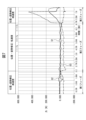
図5と図6を参照して第2の動作例を説明する。図5は、第2の動作例を適用することなく、ロボット10がねじ締め動作において位置・姿勢誤差の修正を行っている場合の力の検出値の実測値の例を示すグラフである。なお、図5において、横軸は時間を表し、縦軸はモーメントを表す。図5に示すグラフは、ロボット10が、力検出器による生の検出値を適用して、つまり標準的なパラメータで位置・姿勢誤差を修正している場合に対応する。図5には、X軸周りのモーメントMx、Y軸周りのモーメントMy、Z軸周りのモーメントMzを図示している。XYZ軸は、図4に示した座標系に対応する。図5に示すように、位置・姿勢誤差の修正の速度が標準的な状況では、力検出器の検出値(ここではモーメント)は、なだらかに変動していくような推移を示す。
The second operation example will be described with reference to Figs. 5 and 6. Fig. 5 is a graph showing an example of actual force detection values when the
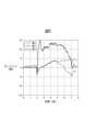
図6は、検出値が図5のように観測される状況において、第2の動作例が実行されているときの、位置・姿勢誤差の修正に適用される力の検出値の推移を示すグラフである。なお、図6において、横軸は時間を表し、縦軸はモーメントに対応する検出値をトルクとして記している。図6におけるトルクT4、T5、T6は、それぞれモーメントMx、My、Mzに対応する。本実施形態に係る速度変更部125は、力検出器の検出値が所定の閾値を超えて大きくなった場合に、位置誤差または姿勢誤差が大きくなっている状態であるとみなし、位置誤差または姿勢誤差が素早く修正されるように、位置・姿勢修正の速度を高速度モード(第1修正速度モード)に設定する。
FIG. 6 is a graph showing the transition of the detection value of the force applied to correct the position/attitude error when the second operation example is being performed in a situation where the detection value is observed as in FIG. 5. In FIG. 6, the horizontal axis represents time, and the vertical axis represents the detection value corresponding to the moment as torque. Torques T4, T5, and T6 in FIG. 6 correspond to moments Mx, My, and Mz, respectively. When the detection value of the force detector becomes large beyond a predetermined threshold, the
ここで、位置・姿勢誤差の修正の高速度モードについて説明する。力制御による位置誤差、姿勢誤差の修正では、位置誤差、姿勢誤差が大きくなるほど、力検出器による検出値(力・モーメント)は大きくなる。そして、力制御では、一般に、これらの検出値の基準値からの偏差に力制御ゲインを乗算して得られた指令値によりロボットを動作させる。なお、偏差の計算における基準値は通常はゼロである。したがって、一般に、力制御の検出値が大きくなるほど位置姿勢の修正の応答速度は高くなる。本実施形態に係る速度変更部125は、一定の時間範囲で力・モーメントの検出値を監視し、検出値の最大値が所定の閾値を超えて大きくなった場合、その一定の時間範囲の間の検出値として、当該最大値(又は、最大値以上の値、最大値に相当する値などの最大値に基づく値であってもよい)を適用し、それにより力制御による位置・姿勢の修正が高速で行われるようにする。位置・姿勢の修正に関するこのような動作モードを、位置・姿勢誤差の修正の高速度モードと称することとする。
Here, the high-speed mode of position and orientation error correction will be described. In the correction of position and orientation errors by force control, the larger the position and orientation errors, the larger the detection value (force and moment) by the force detector. In force control, the robot is generally operated by a command value obtained by multiplying the deviation of these detection values from the reference value by the force control gain. The reference value in the calculation of the deviation is usually zero. Therefore, in general, the larger the detection value of force control, the higher the response speed of the correction of position and orientation. The
位置・姿勢の修正速度について低速度モード(第2修正速度モード)とは、位置・姿勢の修正が上記高速度モードよりも低くなる速度モードを指し、例えば、力検出器の生の検出値をそのまま適用して力制御による位置・姿勢の修正を行う場合(図5に示すような動作)が該当する。 The low-speed mode (second correction speed mode) for the correction speed of the position and attitude refers to a speed mode in which the correction of the position and attitude is slower than in the high-speed mode described above, and corresponds, for example, to the case where the raw detection value of the force detector is directly applied to correct the position and attitude by force control (operation as shown in Figure 5).
図5および図6を参照して、第2の動作例による位置・姿勢誤差の修正の具体的な動作を説明する。速度変更部125は、次のような手順で本動作行う。
(手順1)はじめに、速度変更部125は、本動作例の制御を実行する一定の時間範囲を設定する。
(手順2)速度変更部125は、一定の時間範囲で力・モーメントの検出値について、所定の閾値を超える最大値を検出する(例えば、所定の閾値を超えるピーク値をとらえる)。
(手順3)速度変更部125は、検出した最大値を、位置・姿勢誤差の修正における検出値として適用する(位置・姿勢誤差の修正における検出値をこの最大値に固定する)ことで、位置・姿勢の修正速度を高速度モードに設定する。
(手順4)検出値が閾値以下である場合には、位置・姿勢の修正速度を低速度モードとする(力検出器による生の検出値を、位置・姿勢の誤差の修正における検出値としてそのまま適用する)。
A specific operation for correcting position and orientation errors according to the second operation example will be described with reference to Figures 5 and 6. The
(Step 1) First, the
(Step 2) The
(Step 3) The
(Step 4) If the detection value is equal to or less than the threshold value, the position/orientation correction speed is set to low-speed mode (the raw detection value by the force detector is applied as is as the detection value for correcting the position/orientation error).
手順1において、速度変更部125が、2秒から7秒の範囲を一定の時間範囲として設定し、閾値を15Nと設定しているものとする。そして、手順2において、観測値が図5のようになっており、モーメントMyの最大値(15.01Nm)が閾値(15Nm)を超えたことが検出されたものとする。この場合、速度変更部125は、一定の時間範囲(2秒から7秒)については、モーメントMyの検出値として最大値(15.01Nm)を設定する(図6参照)。これにより、力制御部122は、時間範囲2秒から7秒について、モーメントMyの検出値が15.01Nmであるとみなし(つまり、大きな姿勢誤差が続いているとみなし)、モーメントMyに関する姿勢誤差を高速に修正することとなる(手順3)。
In
速度変更部125は、一定の時間範囲内において検出される力・モーメントが閾値を超えない力・モーメントについては、位置・姿勢のずれがあまりないことから、位置・姿勢の修正の速度を低速度モードとする(手順4)。図5のグラフの例では、モーメントMx、モーメントMzについては検出値が閾値(15Nm)以下であるため、速度変更部125は、モーメントMxに対応するX軸周りの姿勢の修正、および、モーメントMzに対応するZ軸周りの姿勢の修正については低速度モードで位置・姿勢を修正する。
For forces and moments that are detected within a certain time range and do not exceed a threshold value, the
以上のような位置・姿勢についての速度の制御により、ずれが大きい位置や姿勢の方向を的確に検出して修正の速度を向上させることができる。このような第2の動作例も、ねじ締め作業全体のサイクルタイムを短縮することを可能とする。 By controlling the speed of the position and posture as described above, it is possible to accurately detect the direction of the position or posture where there is a large deviation, and improve the speed of correction. This second operation example also makes it possible to shorten the cycle time of the entire screw tightening operation.
速度変更部125は、一定の時間範囲を、2秒から7秒、3秒から8秒、4秒から9秒等と順次ずらしながら上述の手順1から手順4による処理を行うことで、ねじ締め作業全体について、位置・姿勢の速度を変更する制御を実現することができる。
The
図7は、ねじ締め実行中の力検出器の検出値の実測値の例と、その場合の速度変更部125による位置・姿勢誤差の速度の調整の状態を示す図である。なお、ここでの実測値は、図4に示したものと同じである。比較的大きな位置・姿勢誤差が生じている第1フェーズでは、位置・姿勢誤差の修正の作動に伴い、並進方向の検出値(グラフG1)或いはモーメントが比較的大きくなる。第1フェーズにおいて、速度変更部125は、並進力或いはモーメントの検出値の最大値が所定の閾値を超えることを検出し、位置・姿勢の誤差が大きい状態とみなして、位置・姿勢誤差の修正の速度を高速度モードに設定する。
FIG. 7 shows an example of the actual measured values of the force detector during screw tightening, and the state of the speed adjustment of the position/attitude error by the
位置・姿勢誤差が収束する第2フェーズに入ると、並進力或いはモーメントの検出値は小さくなる。並進力或いはモーメントの検出値が閾値以下となることに応じて、速度変更部125は、位置・姿勢誤差の修正の速度を低速度モードに設定する。そして、第3フェーズに入ると、ねじ81はねじ穴91に締め付けられている状態となり、並進力或いはモーメントは閾値を超える大きな値となる。それに応じ、速度変更部125は、位置・姿勢誤差の修正の速度を高速度モードに設定する。
When the second phase begins, in which the position and orientation errors converge, the detection value of the translational force or moment becomes smaller. When the detection value of the translational force or moment falls below the threshold value, the
このように、速度変更部125は、位置・姿勢の誤差の状態を的確に把握して、位置・姿勢の修正の速度を適切に設定することができる。このような動作は、ねじ締め全体における処理時間を短縮可能な部分の処理時間を自動的に短縮することを可能とし、それによりねじ締め全体のサイクルタイムを短縮することを可能とする。
In this way, the
なお、上述の第2の動作例では、一定の時間範囲における力またはモーメントの検出値の最大値であって所定の閾値を超えるものが検出された場合に、その最大値(またはそれ以上の値)を位置・姿勢誤差の修正における検出値として設定することを位置・姿勢誤差の修正の高速度モードと定義した。この定義は一例であり、例えば、位置・姿勢誤差の修正の高速度モードは、一定の時間範囲で力・モーメントの検出値が基準値を超えた場合に、その基準値(またはそれ以上の値)を位置・姿勢誤差の修正における検出値として設定する動作であってもよい。 In the second operation example described above, when a maximum value of a force or moment detection value in a certain time range is detected and exceeds a predetermined threshold, the maximum value (or a value greater than this) is set as the detection value for correcting the position and attitude error, which is defined as the high-speed mode of position and attitude error correction. This definition is one example, and for example, the high-speed mode of position and attitude error correction may be an operation in which, when a detection value of a force or moment in a certain time range exceeds a reference value, the reference value (or a value greater than this) is set as the detection value for correcting the position and attitude error.
位置・姿勢誤差の修正における低速度モードとは、上述の高速度モードよりも位置・姿勢誤差の修正の速度が低速になるような速度モードであればよい。 The low-speed mode for correcting position and orientation errors may be any speed mode in which the speed of correcting position and orientation errors is slower than the high-speed mode described above.
なお、以上では、第2の動作例の位置・姿勢誤差の速度の調整が第1の動作例における力制御の進行速度の調整に加えて実行されるものとして説明したが、第2の動作例の位置・姿勢誤差の速度の調整が第1の動作例における力制御の進行速度の調整に代えて実行されるような動作例もあり得る。すなわち、次のような動作例(第3の動作例)もあり得る。
(第3の動作例)
・第1フェーズでは、位置・姿勢誤差の修正を高速度モードとし、エンドエフェクタの動作速度を低速度モードとする。
・第2フェーズでは、位置・姿勢誤差の修正を低速度モードとし、エンドエフェクタの動作速度を高速度モードとする。
・第3フェーズでは、位置・姿勢誤差の修正を高速度モードとし、エンドエフェクタの動作速度を低速度モードとする。
In the above, the adjustment of the speed of the position/orientation error in the second operation example has been described as being performed in addition to the adjustment of the progress speed of the force control in the first operation example, but there may be an operation example in which the adjustment of the speed of the position/orientation error in the second operation example is performed instead of the adjustment of the progress speed of the force control in the first operation example. That is, the following operation example (third operation example) may also be possible.
(Third operation example)
In the first phase, the position and orientation errors are corrected in a high-speed mode, and the operation speed of the end effector is in a low-speed mode.
In the second phase, the position and orientation errors are corrected in the low-speed mode, and the operation speed of the end effector is set to the high-speed mode.
In the third phase, the position and orientation errors are corrected in high-speed mode, and the operation speed of the end effector is in low-speed mode.
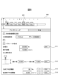
次に、ねじ締め作業を高速化するための、設定部126によるねじ締め作業終了条件の設定機能について説明する。ここでは、ロボット制御装置20は、ロボットの機能命令を表すアイコンによるプログラミングを受付可能に構成され、設定部126は、各アイコンの詳細設定を行う機能を提供できるように構成されているものとする。図8は、設定部126の機能により提供される、ねじ締め機能に対応する機能アイコン301の設定画面300を示している。設定部126は、設定画面300を教示操作盤30の表示部31に表示し、教示操作盤30の操作部を介したユーザ操作による設定画面300への入力を受け付ける。
Next, the function of setting the conditions for ending a screw tightening operation by the
図8に示すように、設定画面300は、力制御によるねじ締めに関する設定項目として目標力、力制御の進行速度、ねじ締め深さ、力終了判定閾値、および速度終了判定閾値を含んでいる。更に、設定画面300は、力制御によるねじ締めの終了条件を設定するための設定ボタン311から314を含んでいる。
(1)設定ボタン311は、ねじ締めの押付力が目標力に到達したことを、ねじ締めの終了条件とすることを設定するためのボタンである。
(2)設定ボタン312は、ねじ締め深さが、指定された最小値から最大値の範囲に入った場合を、ねじ締め終了条件とすることを設定するためのボタンである。
(3)設定ボタン313は、力(押付力)を終了条件とする場合に、押付力がここで指定した閾値(目標力の90%)を超えたことを終了条件とすることを設定するためのボタンである。設定ボタン311および設定ボタン313の双方がオンに設定されている場合、目標力がここで設定した判定閾値を超えた場合にねじ締めを終了する。
(4)設定ボタン314は、ロボット10(ソケット65)の速度がここで設定した判定閾値未満となったことを終了条件とすることを設定するためのボタンである。
なお、ここで示した終了条件(1)から(4)は例示であり、終了条件はこれらに限定されるものではない。例えば、モーメントを終了条件としてもよい。この場合、図8の設定画面に、終了条件としてのモーメントの判定の閾値(終了時モーメント閾値)を設定するための設定項目および設定ボタンを更に設けてもよい。
8, the
(1) The
(2) The
(3) The
(4) The
The termination conditions (1) to (4) shown here are merely examples, and the termination conditions are not limited to these. For example, a moment may be set as the termination condition. In this case, the setting screen of FIG. 8 may further include a setting item and a setting button for setting a threshold value (termination moment threshold value) for determining the moment as the termination condition.
終了条件判定部127は、例えば、オンに設定されている終了条件の全てが満たされたときに、ねじ締めが終了したと判定する。
The termination
設定画面300では、終了条件の各々について終了条件として機能させるか否かを設定可能となっている。したがって、ねじ締めの高速化を意図するユーザは、必要最小限の終了条件をオンにすることで、不要な制御が行われることを回避することができる。例えば、ねじの長さに個体差があるような状況では、ねじ締め深さの監視が重要となる。したがって、このような状況では、設定ボタン312のみをオンするようにしてもよい。
In the
上述の実施形態は、ロボット10に搭載されるねじ締め機構(エンドエフェクタ)としてナットランナが用いられる場合に構成例であったが、ねじ締め機構として、付加軸モータを用いる構成や、ロボットの手首軸を用いる構成例もあり得る。付加軸モータを用いる構成の場合、ロボット10のフランジ11に取付板を取り付け、この取付板に付加軸モータを固定し、この付加軸モータの駆動軸にねじ締め用のソケットを固定する。この構成の場合には、ロボット制御装置20(速度変更部125)は、力検出器の検出値に基づいて、力制御の進行に係わる速度および付加軸モータの回転速度を連携させながら変更する。ロボットの手首軸(手首部の駆動軸)を用いる構成の場合、ロボット10の手首軸にソケットを固定する構成とする。この構成の場合には、ロボット制御装置20(速度変更部125)は、力検出器の検出値に基づいて、力制御の進行に係わる速度および手首軸モータの回転速度を連携させながら変更する。
The above embodiment is an example of a configuration in which a nut runner is used as the screw tightening mechanism (end effector) mounted on the
上述の実施形態は、力制御によるねじ締めを行う場合の速度調整に関する構成例であったが、上述した実施形態における力制御の速度調整に関する構成は、力制御による様々な作業(研磨、バリ取り、精密篏合、倣い、摩擦攪拌接合等)に適用することができる。例えば、図9および図10にそれぞれ示す研磨作業、バリ取り作業を考慮する。 The above-described embodiment is an example of a configuration for adjusting the speed when tightening a screw by force control, but the configuration for adjusting the speed of force control in the above-described embodiment can be applied to various tasks using force control (polishing, deburring, precision fitting, copying, friction stir welding, etc.). For example, consider the polishing task and deburring task shown in Figures 9 and 10, respectively.
図9に示すように研磨作業では、ロボット10Aの手首部のフランジ11Aにエンドエフェクタとして研磨用の工具(サンダまたはバフ)66が回転可能に取り付けられる。例えば、力センサ70が、フランジ11Aと工具66との間に配置される。ロボット制御装置20は、研磨用の動作プログラムに従って、研磨用の工具66を回転させながら対象物W1の表面上に軌跡Tを描くように移動する研磨作業を実行する。ロボット10Aは、押付方向(図9において矢印A方向)の検出力が目標力となるように力制御を行う。
As shown in FIG. 9, in the polishing operation, a polishing tool (sander or buff) 66 is rotatably attached as an end effector to the
図9に示した構成例は、研磨用の工具66をロボット10Aの手首部に配置された手首軸モータにより回転駆動する場合の構成例である。この構成の場合には、ロボット制御装置20(速度変更部125)は、力検出器の検出値に基づいて、力制御の進行に係わる速度および手首軸モータの回転速度を連携させながら変更する。或いは、このような構成例に代えて、ロボット10Aに搭載した付加軸モータにより研磨用の工具66を回転駆動する構成もあり得る。この構成の場合には、ロボット制御装置20(速度変更部125)は、力検出器の検出値に基づいて、力制御の進行に係わる速度および付加軸モータの回転速度を連携させながら変更する。なお、研磨作業の場合には、力制御の進行に係わる速度は、目標軌道(軌跡T)に沿った方向のロボットの移動速度と定義してもよい。なお、研磨作業の場合にも、様々な終了条件を設定して適用することができる。例えば、目標軌道(軌跡T)の長さの移動を完了したこと、目標範囲(作業対象範囲)内の移動を完了したこと、検出力が所定値を超えた/所定値未満となったこと等を終了条件として適用することができる。
The configuration example shown in FIG. 9 is a configuration example in which the
図10に示すように、バリ取り作業では、ロボット10Aの手首部のフランジ11Aにグラインダ67が手首軸の回転により回転可能な状態で取り付けられている。フランジ11Aとグラインダ67との間に力センサ70が配置されている。ロボット10Aはバリ取り用プログラムに従って、グラインダ67を対象ワークW2上の軌跡T2に沿って移動させ、対象ワークW2の稜線にあるバリを除去するように動作する。対象ワークW2の図中左上側の稜線を処理する過程では、図中矢印A1で示す押付方向についてグラインダ67を押し付ける力制御が実行される。また、対象ワークW2の図中手前側の稜線を処理する過程では、図中矢印A2で示す押付方向にグラインダ67を押し付ける力制御が実行される。
As shown in FIG. 10, in the deburring operation, a
図10に示した構成例は、グラインダ67をロボット10Aの手首部に配置された手首軸モータにより回転駆動する場合の構成例である。この構成の場合には、ロボット制御装置20(速度変更部125)は、力検出器の検出値に基づいて、力制御の進行に係わる速度および手首軸モータの回転速度を連携させながら変更する。或いは、このような構成例に代えて、ロボット10Aに搭載した付加軸モータによりグラインダ67を回転駆動する構成もあり得る。この構成の場合には、ロボット制御装置20(速度変更部125)は、力検出器の検出値に基づいて、力制御の進行に係わる速度および付加軸モータの回転速度を連携させながら変更する。なお、バリ取り作業の場合には、力制御の進行に係わる速度は、目標軌道(軌跡T2)に沿った方向のロボットの移動速度と定義してもよい。なお、バリ取り作業の場合にも、様々な終了条件を設定して適用することができる。例えば、目標軌道(軌跡T2)の長さの移動を完了したこと、目標範囲(作業対象範囲)内の移動を完了したこと、検出力が所定値を超えた/所定値未満となったこと等を終了条件として適用することができる。
The configuration example shown in FIG. 10 is a configuration example in which the
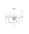
図11は、図9に示した研磨作業や図10に示したバリ取り作業に、上述の実施形態で示した速度調整が適用される場合について説明するための図である。なお、図11では、エンドエフェクタとしてグラインダ67が用いられるバリ取り作業である場合を図示しているが、エンドエフェクタとして工具66が用いられる研磨作業の場合にも同様な動作となる。図11は、ワークW上のバリ取りを行うバリ取り作業において、グラインダ67が比較的大きなバリ等の突起物Mに接触して大きな力が検出された場合の力制御による挙動を示している。このように、グラインダ67が予め教示された経路上で突起物Mに接触した場合、ロボット10はこれを回避する挙動を行うことができる。ここでは、グラインダ67が予め教示された経路R1を進行中に突起物Mに接触し、経路R2、R3及びR4の回避経路をたどり、予め教示された経路R4に復帰する状況を示している。なお、図11は、グラインダ67が突起物Mを回避する挙動を概念的に示したものであり、例えば、力制御によるグラインダ67の押付方向が図11の紙面奥方向であるとき、回避の経路R2からR3は、実際には図11の紙面手前方向に回避するような経路であってもよい。
11 is a diagram for explaining a case where the speed adjustment shown in the above embodiment is applied to the grinding operation shown in FIG. 9 and the deburring operation shown in FIG. 10. Note that FIG. 11 illustrates a case where the
ロボットがこのような挙動を行うとき、本実施形態に係る速度変更部125は、突起物Mとの接触により大きな力(閾値をこえる力・モーメント)が検出されたことに伴い、ロボットが回避動作を行う際の経路R2、R3及びR4での力制御の進行速度を低速度モードに設定し、グラインダ67の回転速度を低速度モードに設定することができる。そして、速度変更部125は、グラインダ67が教示された経路R5に復帰したときに、力制御の進行速度を高速度モードとし、グラインダ67の回転速度を高速度モードに設定することができる。
When the robot behaves in this way, the
このような構成により、突起物Mに接触した場合に力制御の進行速度を低速にし、グラインダの回転速度も低下させることで、グラインダ67が比較的大きな突起物M等に接触した場合にロボットが不要な挙動をとることを回避し、動作を安定化することができる。これにより、作業全体としてのサイクルタイムを削減することが可能となる。
With this configuration, the force control progress speed is slowed down when the grinder comes into contact with a protrusion M, and the rotation speed of the grinder is also reduced, which makes it possible to prevent the robot from behaving unnecessarily when the
図11で説明したような動作は、図9で示したような研磨作業においても同様に適用することができる。 The operation described in FIG. 11 can also be applied to the polishing operation shown in FIG. 9.
図12は、ロボット制御装置20による上述した実施形態による力制御の速度調整処理をフローチャートとして示したものである。なお、ここでは、上述の第1の動作例と第2の動作例が適用された場合の速度調整処理を説明する。
FIG. 12 is a flowchart showing the speed adjustment process of the force control according to the above-mentioned embodiment by the
はじめに、ユーザにより、力制御に関するパラメータを教示する(ステップS1)。ここでは、例えば、目標力、進行速度、ねじ締め深さ、力制御ゲインその他の各種パラメータの設定が行われる。次に、ユーザは、図8の設定画面を介して力制御動作の終了条件の設定を行う(ステプS2)。 First, the user instructs the parameters related to force control (step S1). Here, for example, the target force, progress speed, screw tightening depth, force control gain, and other various parameters are set. Next, the user sets the end conditions for the force control operation via the setting screen in Figure 8 (step S2).
そして、ロボット制御装置20(速度変更部125)は、ロボット10による力制御の作業を開始させ、力・モーメント、終了条件のパラメータ等を含む各種パラメータの監視を行う(ステップS3)。次に、ロボット制御装置20(速度変更部125)は、力の検出値(力・モーメント)が閾値を超えて大きくなっているか否かを判定する(ステップS4)。検出値(力・モーメント)が閾値を超えていると判定される場合(S4:YES)、ロボット制御装置20(速度変更部125)は、力制御の進行速度を低速度モードに設定し、ねじ締め機(ナットランナー)60の回転速度を低速度モードに設定し、位置・姿勢の修正の速度を高速度モードに設定する(ステップS5)。
Then, the robot controller 20 (speed change unit 125) starts the force control operation by the
他方、ステップS4において、検出値(力・モーメント)が閾値以下であると判定される場合(S4:NO)、ロボット制御装置20(速度変更部125)は、力制御の進行速度を高速度モードに設定し、ねじ締め機(ナットランナー)60の回転速度を高速度モードに設定し、位置・姿勢の修正の速度を低速度モードに設定する(ステップS6)。 On the other hand, if it is determined in step S4 that the detection value (force/moment) is equal to or less than the threshold value (S4: NO), the robot control device 20 (speed change unit 125) sets the force control progress speed to high speed mode, sets the rotation speed of the screw tightening machine (nut runner) 60 to high speed mode, and sets the position/posture correction speed to low speed mode (step S6).
そして、ロボット制御装置20は、力制御による作業を進行させる(ステップS7)。次に、ロボット制御装置20(終了条件判定部127)は、ユーザにより設定された終了条件が満たされたか否かを判定する(スッテプS8)。終了条件が未だ満たされていない場合には(S8:NO)、ステップS3からの処理が繰り返される。終了条件が満たされている場合(S8:YES)、作業を終了する。
Then, the
以上説明した各実施形態によれば、力・モーメントの検出値に応じて力制御による作業の進行に係わる速度を調整することが可能となり、力制御の動作における速度を高速に実行できる部分の速度を高速化することが可能となる。また、力制御の進行に係わる速度とエンドエフェクタの動作速度とを連携して調整することができるため、力制御による作業を安定して的確に実行することも可能である。 According to each of the embodiments described above, it is possible to adjust the speed related to the progress of work by force control according to the detected values of force and moment, and it is possible to increase the speed of parts of the force control operation that can be performed at high speed. In addition, since the speed related to the progress of force control and the operation speed of the end effector can be adjusted in conjunction with each other, it is also possible to stably and accurately perform work by force control.
なお、上述した実施形態では、力制御の進行に係わる速度と、エンドエフェクタの動作速度とを高速度モードと、低速度モードの2段階で切り替える構成について説明したが、力検出器の検出値に応じて力制御の進行に係わる速度と、エンドエフェクタの動作速度とを3段階以上の多段階に切り替えるようにすることも可能である。例えば、上述の「第1の動作例」に関しては、力・モーメントの検出値に2種類の閾値(第1閾値、第1閾値より低い第2閾値)を適用することで、
・力・モーメントの検出値が第1閾値を超える場合に第1速度モード(最も高速な速度モード)とし、
・力・モーメントの検出値が第1閾値以下で且つ第2閾値を超える場合に第2速度モード(2番目に高速な速度モード)とし、
・力・モーメントの検出値が第2閾値以下である場合に第3速度モード(最も低速な速度モード)としてもよい。
In the above embodiment, the configuration has been described in which the speed related to the progress of force control and the operation speed of the end effector are switched between two levels, a high-speed mode and a low-speed mode, but it is also possible to switch the speed related to the progress of force control and the operation speed of the end effector between three or more levels depending on the detection value of the force detector. For example, with regard to the above-mentioned "first operation example," by applying two types of thresholds (a first threshold and a second threshold lower than the first threshold) to the detection value of the force/moment,
When the detected value of the force/moment exceeds the first threshold, the first speed mode (the fastest speed mode) is selected;
When the detected force/moment value is equal to or less than the first threshold value and exceeds the second threshold value, the second speed mode (the second fastest speed mode) is selected;
When the detected value of the force/moment is equal to or less than the second threshold value, the third speed mode (the slowest speed mode) may be selected.
上述の「第2の動作例」に関しても同様に3段階の速度調整を行うことが理解できる。なお、「第2の動作例」においては、位置・姿勢誤差の修正において適用する(力制御部122に入力する)検出値の大きさを調整することで、位置・姿勢誤差の修正の速度を調整することができる。 It can be seen that the above-mentioned "second operation example" also has three stages of speed adjustment. Note that in the "second operation example", the speed of position/orientation error correction can be adjusted by adjusting the magnitude of the detection value applied (input to the force control unit 122) in correcting the position/orientation error.
以上説明した実施形態において図2を参照して説明した機能ブロック図の機能配分はレジであり、機能ブロックの機能配分については様々な変形例を構成することができる。例えば、図2においてロボット制御装置20に配置された機能ブロックの少なくとも一部(例えば、設定部126)を教示操作盤30に配置するような構成例もあり得る。
In the embodiment described above, the functional allocation of the functional block diagram described with reference to FIG. 2 is a cash register, and various modified examples of the functional allocation of the functional blocks can be configured. For example, there can be a configuration example in which at least a portion of the functional blocks (e.g., setting unit 126) arranged in the
教示操作盤30は、ロボット制御装置20の操作端末として機能することから、教示操作盤30の機能も含めてロボット制御装置の20の機能と定義することもできる。
Since the
上述の実施形態で説明した構成は、ツールを搭載して力制御による作業を実行し得る様々なタイプの機械の制御装置に適用することができる。 The configuration described in the above embodiment can be applied to control devices for various types of machines that can be equipped with tools and perform work using force control.
図2に示した機能ブロックは、ロボット制御装置の1又は複数のプロセッサが、記憶装置に格納された各種ソフトウェアを実行することで実現されても良く、或いは、ASIC(Application Specific Integrated Circuit)等のハードウェアを主体とした構成により実現されても良い。 The functional blocks shown in FIG. 2 may be realized by one or more processors in the robot control device executing various software stored in a storage device, or may be realized by a hardware-based configuration such as an ASIC (Application Specific Integrated Circuit).
上述した実施形態における、力制御の進行速度、位置・姿勢誤差の修正の速度、およびエンドエフェクタの動作速度の調整に係わる各種処理を実行するためのプログラムは、コンピュータに読み取り可能な各種記録媒体(例えば、ROM、EEPROM、フラッシュメモリ等の半導体メモリ、磁気記録媒体、CD-ROM、DVD-ROM等の光ディスク)に記録することができる。 In the above-described embodiment, the programs for executing various processes related to adjusting the progress speed of force control, the speed of correction of position and orientation errors, and the operating speed of the end effector can be recorded on various computer-readable recording media (for example, semiconductor memory such as ROM, EEPROM, flash memory, magnetic recording media, and optical disks such as CD-ROM and DVD-ROM).
以上説明したように各実施形態によれば、力制御の動作を的確に実行しつつ力制御による作業全体のサイクルタイムを短縮化することが可能となる。 As described above, according to each embodiment, it is possible to shorten the cycle time of the entire work performed by force control while accurately executing the force control operation.
本開示について詳述したが、本開示は上述した個々の実施形態に限定されるものではない。これらの実施形態は、本開示の要旨を逸脱しない範囲で、または、特許請求の範囲に記載された内容とその均等物から導き出される本開示の趣旨を逸脱しない範囲で、種々の追加、置き換え、変更、部分的削除等が可能である。また、これらの実施形態は、組み合わせて実施することもできる。例えば、上述した実施形態において、各動作の順序や各処理の順序は、一例として示したものであり、これらに限定されるものではない。また、上述した実施形態の説明に数値又は数式が用いられている場合も同様である。 Although the present disclosure has been described in detail, the present disclosure is not limited to the individual embodiments described above. Various additions, substitutions, modifications, partial deletions, etc. are possible to these embodiments without departing from the gist of the present disclosure, or without departing from the spirit of the present disclosure derived from the contents described in the claims and their equivalents. These embodiments can also be implemented in combination. For example, in the above-mentioned embodiments, the order of each operation and the order of each process are shown as examples, and are not limited to these. The same applies when numerical values or formulas are used to explain the above-mentioned embodiments.
上記実施形態および変形例に関し更に以下の付記を記載する。
(付記1)
エンドエフェクタを搭載し所定の作業を実行するロボット(10)を制御する制御装置(20)であって、前記ロボット(10)に作用する力およびモーメントを検出可能な力検出器(70)からの検出値に基づいて力制御を実行する力制御部(122)と、前記力制御による動作が実行されているときに、前記力検出器(70)の検出値に基づいて、前記力制御の進行に係わる速度および前記エンドエフェクタの動作速度を連携させながら変更する速度変更部(125)と、を備える制御装置(20)。
(付記2)
前記力制御の進行に係わる速度は、前記力制御の目標力の方向における進行速度、または、目標軌道に沿った方向の進行速度を含む、付記1に記載の制御装置(20)。
(付記3)
前記速度変更部(125)は、
前記検出値が所定の閾値を超えたときに、前記力制御の進行速度を第1速度モードとすると共に、前記エンドエフェクタの動作速度を第1動作速度モードとし、
前記検出値が前記所定の閾値以下となったときに、前記力制御の進行速度を前記第1速度モードよりも高速の第2速度モードとすると共に、前記エンドエフェクタの動作速度を前記第1動作速度モードよりも高速の第2動作速度モードとする、付記2に記載の制御装置(20)。
(付記4)
前記力制御の進行に係わる速度は、前記力制御における位置誤差または姿勢誤差の修正の速度を含む、付記1から3のいずれか一項に記載の制御装置(20)。
(付記5)
前記速度変更部(125)は、
前記検出値が所定の閾値を超えたときに、前記位置誤差又は姿勢誤差の修正の速度を第1修正速度モードとし、
前記検出値が所定の閾値以下となったときに、前記位置誤差又は姿勢誤差の修正の速度を前記第1修正速度モードよりも低速の第2修正速度モードとする、付記4に記載の制御装置(20)。
(付記6)
前記速度変更部(125)は、一定の時間範囲内で検出される前記検出値の最大値または当該最大値に基づく値を、位置又は姿勢の誤差を修正するために力またはモーメントの検出値と基準値との偏差に力制御ゲインを乗じて前記ロボットに対する指令値を算出する場合の計算に適用することで、前記第1修正速度モードを設定する、付記5に記載の制御装置(20)。
(付記7)
前記力制御による動作を終了するための所定の複数の終了条件のうち、指定された1以上の終了条件に基づいて前記力制御による動作を終了する終了条件判定部(127)を更に備える、付記1から6のいずれか一項に記載の制御装置(20)。
(付記8)
前記複数の終了条件は、
(1)押付力が目標力に達したこと、
(2)ねじ締め深さが指定された範囲に到達したこと、
(3)押付力が目標力に対して設定された判定閾値を超えたこと、
(4)ロボットの動作速度が、指定された判定閾値未満に低下したこと、
のうちの二つ以上を含む、
付記7に記載の制御装置(20)。
(付記9)
前記所定の作業はねじ締め作業であり、前記エンドエフェクタはねじ締め機構であり、前記エンドエフェクタの動作速度は前記ねじ締め機構の回転速度である、付記1から8のいずれか一項に記載の制御装置(20)。
(付記10)
前記ねじ締め機構は、ナットランナ、付加軸モータ、又は前記ロボットの手首軸のいずれかを用いる、付記9に記載の制御装置(20)。
(付記11)
前記所定の作業は研磨作業であり、前記エンドエフェクタは研磨用の工具(66)であり、前記エンドエフェクタの動作速度は前記研磨用の工具(66)の回転速度である、付記1から7のいずれか一項に記載の制御装置(20)。
(付記12)
前記研磨用の工具(66)は、付加軸モータ、又は前記ロボット(10)の手首軸を用いる、付記11に記載の制御装置(20)。
(付記13)
前記所定の作業はバリ取り作業であり、前記エンドエフェクタはグラインダ(67)であり、前記エンドエフェクタの動作速度は前記グラインダ(67)の回転速度である、付記1から7のいずれか一項に記載の制御装置(20)。
(付記14)
前記グラインダ(67)は、付加軸モータ、又は前記ロボット(10)の手首軸を用いる、付記13に記載の制御装置(20)。
The following additional notes are provided regarding the above embodiment and modifications.
(Appendix 1)
A control device (20) for controlling a robot (10) equipped with an end effector and performing a specified task, the control device (20) comprising: a force control unit (122) that performs force control based on detection values from a force detector (70) capable of detecting forces and moments acting on the robot (10); and a speed change unit (125) that changes, in coordination with each other, a speed related to the progress of the force control and the operating speed of the end effector based on the detection value of the force detector (70) when an operation based on the force control is being performed.
(Appendix 2)
The control device (20) of
(Appendix 3)
The speed change unit (125)
When the detection value exceeds a predetermined threshold, a proceeding speed of the force control is set to a first speed mode, and an operation speed of the end effector is set to a first operation speed mode;
The control device (20) described in
(Appendix 4)
4. The control device (20) of
(Appendix 5)
The speed change unit (125)
When the detection value exceeds a predetermined threshold, a speed of correction of the position error or the attitude error is set to a first correction speed mode;
The control device (20) according to
(Appendix 6)
The control device (20) described in
(Appendix 7)
The control device (20) according to any one of
(Appendix 8)
The plurality of termination conditions are:
(1) The pressing force reaches a target force.
(2) The screw tightening depth has reached the specified range.
(3) The pressing force exceeds a judgment threshold value set for the target force.
(4) The robot's movement speed has fallen below a specified judgment threshold;
Two or more of the following are included:
8. The control device (20) according to
(Appendix 9)
9. The control device (20) of any one of
(Appendix 10)
10. The control device (20) of claim 9, wherein the screw tightening mechanism uses either a nut runner, an additional axis motor, or a wrist axis of the robot.
(Appendix 11)
A control device (20) as described in any one of
(Appendix 12)
12. The control device (20) of
(Appendix 13)
8. The control device (20) of any one of
(Appendix 14)
The control device (20) of claim 13, wherein the grinder (67) uses an additional axis motor or a wrist axis of the robot (10).
10 ロボット
11 フランジ
20 ロボット制御装置
30 教示操作盤
51 取付板
60 ねじ締め機
65 ソケット
61 本体部
62 ヘッド部
70 力センサ
100 ロボットシステム
111 モータ
121 動作制御部
122 力制御部
123 パラメータ調整部
124 力データ処理部
125 速度変更部
126 設定部
127 終了条件判定部
161 制御部
162 モータ
REFERENCE SIGNS
Claims (14)
前記ロボットに作用する力およびモーメントを検出可能な力検出器からの検出値に基づいて力制御を実行する力制御部と、
前記力制御による動作が実行されているときに、前記力検出器の検出値に基づいて、前記力制御の進行に係わる速度および前記エンドエフェクタの動作速度を連携させながら変更する速度変更部と、
を備える制御装置。 A control device for controlling a robot equipped with an end effector and performing a predetermined task,
a force control unit that executes force control based on a detection value from a force detector that can detect forces and moments acting on the robot;
a speed change unit that changes a speed related to the progress of the force control and a motion speed of the end effector in a coordinated manner based on a detection value of the force detector when the motion based on the force control is being executed;
A control device comprising:
前記検出値が所定の閾値を超えたときに、前記力制御の進行速度を第1速度モードとすると共に、前記エンドエフェクタの動作速度を第1動作速度モードとし、
前記検出値が前記所定の閾値以下となったときに、前記力制御の進行速度を前記第1速度モードよりも高速の第2速度モードとすると共に、前記エンドエフェクタの動作速度を前記第1動作速度モードよりも高速の第2動作速度モードとする、請求項2に記載の制御装置。 The speed change unit is
When the detection value exceeds a predetermined threshold, a proceeding speed of the force control is set to a first speed mode, and an operation speed of the end effector is set to a first operation speed mode;
3. The control device according to claim 2, wherein when the detection value becomes equal to or less than the predetermined threshold, a proceeding speed of the force control is set to a second speed mode faster than the first speed mode, and an operating speed of the end effector is set to the second operating speed mode faster than the first operating speed mode.
前記検出値が所定の閾値を超えたときに、前記位置誤差又は姿勢誤差の修正の速度を第1修正速度モードとし、
前記検出値が所定の閾値以下となったときに、前記位置誤差又は姿勢誤差の修正の速度を前記第1修正速度モードよりも低速の第2修正速度モードとする、請求項4に記載の制御装置。 The speed change unit is
When the detection value exceeds a predetermined threshold, a speed of correction of the position error or the attitude error is set to a first correction speed mode;
5. The control device according to claim 4, wherein, when the detected value becomes equal to or smaller than a predetermined threshold value, a speed of correction of the position error or the attitude error is set to a second correction speed mode slower than the first correction speed mode.
(1)押付力が目標力に達したこと、
(2)ねじ締め深さが指定された範囲に到達したこと、
(3)押付力が目標力に対して設定された判定閾値を超えたこと、
(4)ロボットの動作速度が、指定された判定閾値未満に低下したこと、
のうちの二つ以上を含む、
請求項7に記載の制御装置。 The plurality of termination conditions are:
(1) The pressing force reaches a target force.
(2) The screw tightening depth has reached the specified range.
(3) The pressing force exceeds a judgment threshold value set for the target force.
(4) The robot's movement speed has fallen below a specified judgment threshold;
Two or more of the following are included:
The control device according to claim 7.
Priority Applications (3)
| Application Number | Priority Date | Filing Date | Title |
|---|---|---|---|
| PCT/JP2023/030298 WO2025041295A1 (en) | 2023-08-23 | 2023-08-23 | Control device |
| CN202380101160.2A CN121646522A (en) | 2023-08-23 | 2023-08-23 | Control device |
| TW113127469A TW202508788A (en) | 2023-08-23 | 2024-07-23 | Control device |
Applications Claiming Priority (1)
| Application Number | Priority Date | Filing Date | Title |
|---|---|---|---|
| PCT/JP2023/030298 WO2025041295A1 (en) | 2023-08-23 | 2023-08-23 | Control device |
Publications (1)
| Publication Number | Publication Date |
|---|---|
| WO2025041295A1 true WO2025041295A1 (en) | 2025-02-27 |
Family
ID=94731706
Family Applications (1)
| Application Number | Title | Priority Date | Filing Date |
|---|---|---|---|
| PCT/JP2023/030298 Pending WO2025041295A1 (en) | 2023-08-23 | 2023-08-23 | Control device |
Country Status (3)
| Country | Link |
|---|---|
| CN (1) | CN121646522A (en) |
| TW (1) | TW202508788A (en) |
| WO (1) | WO2025041295A1 (en) |
Citations (4)
| Publication number | Priority date | Publication date | Assignee | Title |
|---|---|---|---|---|
| JPH09155738A (en) * | 1995-12-08 | 1997-06-17 | Meidensha Corp | Control mechanism of robot |
| JP2011041992A (en) * | 2009-08-19 | 2011-03-03 | Fanuc Ltd | Machining robot system |
| JP2017209754A (en) * | 2016-05-26 | 2017-11-30 | ファナック株式会社 | Grinding robot system |
| WO2022138380A1 (en) * | 2020-12-22 | 2022-06-30 | ファナック株式会社 | Screw fastening system |
-
2023
- 2023-08-23 CN CN202380101160.2A patent/CN121646522A/en active Pending
- 2023-08-23 WO PCT/JP2023/030298 patent/WO2025041295A1/en active Pending
-
2024
- 2024-07-23 TW TW113127469A patent/TW202508788A/en unknown
Patent Citations (4)
| Publication number | Priority date | Publication date | Assignee | Title |
|---|---|---|---|---|
| JPH09155738A (en) * | 1995-12-08 | 1997-06-17 | Meidensha Corp | Control mechanism of robot |
| JP2011041992A (en) * | 2009-08-19 | 2011-03-03 | Fanuc Ltd | Machining robot system |
| JP2017209754A (en) * | 2016-05-26 | 2017-11-30 | ファナック株式会社 | Grinding robot system |
| WO2022138380A1 (en) * | 2020-12-22 | 2022-06-30 | ファナック株式会社 | Screw fastening system |
Also Published As
| Publication number | Publication date |
|---|---|
| CN121646522A (en) | 2026-03-10 |
| TW202508788A (en) | 2025-03-01 |
Similar Documents
| Publication | Publication Date | Title |
|---|---|---|
| JP3681431B2 (en) | Servo system with adjustable softness on Cartesian coordinate system | |
| JP6457435B2 (en) | Grinding robot system | |
| US9937594B2 (en) | Method of machining workpiece by cooperation of machine tool and robot | |
| CN102365595A (en) | Numerical control device and method of controlling the numerical control device | |
| US11660742B2 (en) | Teaching method and robot system | |
| JP7124439B2 (en) | Control device and robot system | |
| JPH074765B2 (en) | Curved surface processing equipment | |
| JP6693939B2 (en) | Robot system | |
| JP5011507B2 (en) | Robot teaching system and robot teaching method | |
| WO2025041295A1 (en) | Control device | |
| CN116460862B (en) | Master-slave robot system | |
| JP7387999B2 (en) | Articulated robot device | |
| JP7525593B2 (en) | Machine tool control device and control method | |
| JP7658142B2 (en) | ROBOT CONTROL METHOD, ROBOT SYSTEM, AND ROBOT CONTROL PROGRAM | |
| EP4067012B1 (en) | Method for controlling robot, robot system, and program for controlling robot | |
| WO2023062686A1 (en) | Robot control device and robot system | |
| WO2003068463A1 (en) | Robot control device | |
| WO2024176466A1 (en) | Control device and robot system | |
| US20240189986A1 (en) | Robot system and controller | |
| US12290942B2 (en) | Method for controlling robot, robot system, and storage medium | |
| WO2025004194A1 (en) | Control device, robot system, and control method | |
| WO2025027706A1 (en) | Control device | |
| JPH0962335A (en) | Position teaching method using soft floating function | |
| JPH1177572A (en) | Robot control device | |
| WO2026078878A1 (en) | Teaching device, robot system, and method for creating teaching program |
Legal Events
| Date | Code | Title | Description |
|---|---|---|---|
| 121 | Ep: the epo has been informed by wipo that ep was designated in this application |
Ref document number: 23949753 Country of ref document: EP Kind code of ref document: A1 |
|
| ENP | Entry into the national phase |
Ref document number: 2025541241 Country of ref document: JP Kind code of ref document: A |
|
| WWE | Wipo information: entry into national phase |
Ref document number: 2025541241 Country of ref document: JP |