WO2025041281A1 - Appareil de test et procédé de test - Google Patents
Appareil de test et procédé de test Download PDFInfo
- Publication number
- WO2025041281A1 WO2025041281A1 PCT/JP2023/030205 JP2023030205W WO2025041281A1 WO 2025041281 A1 WO2025041281 A1 WO 2025041281A1 JP 2023030205 W JP2023030205 W JP 2023030205W WO 2025041281 A1 WO2025041281 A1 WO 2025041281A1
- Authority
- WO
- WIPO (PCT)
- Prior art keywords
- under test
- device under
- voltage
- test
- measurement
- Prior art date
- Legal status (The legal status is an assumption and is not a legal conclusion. Google has not performed a legal analysis and makes no representation as to the accuracy of the status listed.)
- Pending
Links
Images

Classifications
-
- G—PHYSICS
- G01—MEASURING; TESTING
- G01R—MEASURING ELECTRIC VARIABLES; MEASURING MAGNETIC VARIABLES
- G01R31/00—Arrangements for testing electric properties; Arrangements for locating electric faults; Arrangements for electrical testing characterised by what is being tested not provided for elsewhere
- G01R31/28—Testing of electronic circuits, e.g. by signal tracer
- G01R31/2851—Testing of integrated circuits [IC]
- G01R31/2855—Environmental, reliability or burn-in testing
- G01R31/2872—Environmental, reliability or burn-in testing related to electrical or environmental aspects, e.g. temperature, humidity, vibration, nuclear radiation
- G01R31/2879—Environmental, reliability or burn-in testing related to electrical or environmental aspects, e.g. temperature, humidity, vibration, nuclear radiation related to electrical aspects, e.g. to voltage or current supply or stimuli or to electrical loads
-
- G—PHYSICS
- G01—MEASURING; TESTING
- G01R—MEASURING ELECTRIC VARIABLES; MEASURING MAGNETIC VARIABLES
- G01R1/00—Details of instruments or arrangements of the types included in groups G01R5/00 - G01R13/00 and G01R31/00
- G01R1/20—Modifications of basic electric elements for use in electric measuring instruments; Structural combinations of such elements with such instruments
- G01R1/206—Switches for connection of measuring instruments or electric motors to measuring loads
-
- G—PHYSICS
- G01—MEASURING; TESTING
- G01R—MEASURING ELECTRIC VARIABLES; MEASURING MAGNETIC VARIABLES
- G01R1/00—Details of instruments or arrangements of the types included in groups G01R5/00 - G01R13/00 and G01R31/00
- G01R1/30—Structural combination of electric measuring instruments with basic electronic circuits, e.g. with amplifier
-
- G—PHYSICS
- G01—MEASURING; TESTING
- G01R—MEASURING ELECTRIC VARIABLES; MEASURING MAGNETIC VARIABLES
- G01R31/00—Arrangements for testing electric properties; Arrangements for locating electric faults; Arrangements for electrical testing characterised by what is being tested not provided for elsewhere
- G01R31/26—Testing of individual semiconductor devices
- G01R31/2601—Apparatus or methods therefor
-
- G—PHYSICS
- G01—MEASURING; TESTING
- G01R—MEASURING ELECTRIC VARIABLES; MEASURING MAGNETIC VARIABLES
- G01R31/00—Arrangements for testing electric properties; Arrangements for locating electric faults; Arrangements for electrical testing characterised by what is being tested not provided for elsewhere
- G01R31/28—Testing of electronic circuits, e.g. by signal tracer
- G01R31/2832—Specific tests of electronic circuits not provided for elsewhere
- G01R31/2834—Automated test systems [ATE]; using microprocessors or computers
-
- G—PHYSICS
- G01—MEASURING; TESTING
- G01R—MEASURING ELECTRIC VARIABLES; MEASURING MAGNETIC VARIABLES
- G01R31/00—Arrangements for testing electric properties; Arrangements for locating electric faults; Arrangements for electrical testing characterised by what is being tested not provided for elsewhere
- G01R31/28—Testing of electronic circuits, e.g. by signal tracer
- G01R31/2851—Testing of integrated circuits [IC]
- G01R31/2855—Environmental, reliability or burn-in testing
- G01R31/286—External aspects, e.g. related to chambers, contacting devices or handlers
- G01R31/2868—Complete testing stations; systems; procedures; software aspects
- G01R31/287—Procedures; Software aspects
-
- G—PHYSICS
- G01—MEASURING; TESTING
- G01R—MEASURING ELECTRIC VARIABLES; MEASURING MAGNETIC VARIABLES
- G01R31/00—Arrangements for testing electric properties; Arrangements for locating electric faults; Arrangements for electrical testing characterised by what is being tested not provided for elsewhere
- G01R31/28—Testing of electronic circuits, e.g. by signal tracer
- G01R31/2851—Testing of integrated circuits [IC]
- G01R31/2882—Testing timing characteristics
Definitions
- the first measurement unit may measure a value corresponding to a current flowing through the device under test of the test subject in response to the application of the first voltage from the first power supply, or may measure a value corresponding to a voltage generated in the device under test of the test subject in response to the flow of the first current from the first power supply.
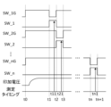
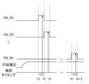
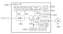
- 1 shows a test system 1 according to a first embodiment. The operation of the test device 2 will be described. 4 shows operational waveforms of the test device 2. 1 shows a test system 1A according to a second embodiment. 4 shows the operating waveforms of the test device 2A. 22 illustrates an example computer 2200 in which aspects of the present invention may be embodied, in whole or in part.
- First Embodiment 1 shows a test system 1 according to the present embodiment.
- the test system 1 includes a plurality of devices under test 10 and a test apparatus 2.
- the devices under test 10 are referred to as DUTs (Device Under Test).
- Each device under test 10 is an electronic device to be tested by the test apparatus 2.
- Each device under test 10 may be, for example, an integrated circuit including a semiconductor, a discrete semiconductor element, or another type of device.
- Each device under test 10 may have at least one connection terminal 101 that is connected to the test apparatus 2.
- Each device under test 10 may further have another connection terminal (not shown) that is connected to a ground voltage.
- Test device 2 The test apparatus 2 tests each device under test 10.
- the test apparatus 2 may test the quality of electrical static characteristics of each device under test 10 that has been connected in advance.
- the test apparatus 2 may sequentially switch between a device under test 10 as a test target among a plurality of devices under test 10 (in the present embodiment, n devices under test 10 (where n is a natural number of 2 or more) as an example).
- the order of the devices under test 10 may be set according to the connection positions to the test apparatus 2.
- the device under test 10 at one end may be the first device under test 10
- the device under test 10 at the other end may be the nth device under test 10.
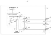
- the test device 2 has a constant voltage generating current measuring unit 20, a first switch unit 21, a second voltage source 23, a second switch unit 24, a constant current generating voltage measuring unit 25, a third switch unit 26, a judgment unit 27, and a test controller 28.
- the constant voltage generating current measuring section 20 measures a value corresponding to a current flowing through the device under test 10 in response to application of a constant voltage to the device under test 10.
- the constant voltage generating current measuring section 20 has a first voltage source 201, an amplifier 202, and a current sensor 203.
- the amplifier 202 is provided between the first voltage source 201 and the current sensor 203 to configure a voltage follower circuit.
- the output terminal of the amplifier 202 is connected to the current sensor 203, and is also connected to an inverting input terminal via the current sensor 203.
- the gain of the amplifier 202 may be 1 (0 dB), and the first voltage output from the first voltage source 201 may be output from the output terminal.
- the current sensor 203 is provided between the output terminal of the amplifier 202 and the first switch section 21.
- the current sensor 203 is an example of a first measurement section, and measures electrical characteristics of the device under test 10 in response to the first voltage source 201 being connected to the device under test 10.
- the current sensor 203 may measure a value corresponding to a current flowing through the device under test 10 in response to the application of a first voltage from the first voltage source 201.
- the current sensor 203 measures the current itself flowing between the output terminal of the amplifier 202 and the first switch section 21, but the measurement may be performed at another position, or another value corresponding to the current (for example, a voltage generated across a resistor in response to the current) may be measured.
- the current sensor 203 may supply the measurement value to the judgment section 27.
- the first switch section 21 is provided between the constant voltage generating current measuring section 20 and the n number of devices under test 10.
- the first switch section 21 connects the connection terminal 101 of the device under test 10 to be tested, among the connection terminals 101 of the n number of devices under test 10, to the first voltage source 201.
- the first switch section 21 may alternatively connect the connection terminal 101 of the device under test 10 to be tested to the first voltage source 201.
- the first switch section 21 may have n number of switches 210, one end of which is connected to the output terminal of the amplifier 202 in the constant voltage generating current measuring section 20 and the other end of which is connected to each of the connection terminals 101 of the n number of devices under test 10.
- the other end of the Nth switch 210 (where N is a natural number such that 1 ⁇ N ⁇ n) of the n number of switches 210 may be connected to the connection terminal 101 of the Nth device under test 10.
- Each switch 210 may be controlled by a test controller 28 described later.
- the second voltage source 23 outputs a second voltage of a predetermined magnitude.
- the second voltage source 23 may output the second voltage of a predetermined magnitude to the connection terminal 101 of at least one other device under test 10 other than the device under test 10 to be tested among the n devices under test 10.
- the second voltage source 23 according to the present embodiment may output the second voltage to at least one device under test 10 other than the device under test to be tested, in cooperation with the second switch section 24.
- the device under test 10 from which the second voltage is output may include, among the n devices under test 10, a device under test 10 that is measured by the current sensor 203 after the device under test 10 being tested, or may include a device under test 10 that is measured before the device under test 10 being tested, or may include a device under test 10 that is placed near the device under test 10 being tested.
- the device under test 10 from which the second voltage is output may be each of the n-1 devices under test 10 that are different from the device under test 10 being tested, among the n devices under test 10.
- the second voltage source 23 may output the second voltage in parallel with the measurement by the current sensor 203, and may output a voltage over the measurement period by the current sensor 203.
- the second voltage source 23 may be an amplifier that amplifies the first voltage output from the first voltage source 201 with a preset gain, and may output a voltage in parallel with the voltage output by the first voltage source 201.
- the amplifier as the second voltage source 23 may be connected to the amplifier 202 of the constant voltage generating current measuring unit 20 to form a voltage follower circuit, and may have a gain of 1 (0 dB).
- the second voltage may be a voltage for passing a current through a device under test 10 other than the test subject to settle the device under test 10 to a standby potential, that is, a standby voltage.
- the second voltage may be a voltage closer to the first voltage than the ground voltages of the n devices under test 10, and in this embodiment, as an example, may be a voltage the same magnitude as the first voltage.
- the current path flowing in the test apparatus 2 due to the voltage from the second voltage source 23 may be insulated from the path of the current flowing in the test apparatus 2 due to the voltage from the first voltage source 201.
- the second voltage source 23 is an amplifier, so the input side and the output side are insulated.
- the current path between the second voltage source 23 and each device under test 10 that is not the test subject, and the current path between the first voltage source 201 and the device under test 10 that is the test subject are separate paths that have no common parts and are insulated from each other.
- the second switch section 24 may connect the constant current generation voltage measurement section 25 to the connection terminal 101 of the device under test 10 that is the subject of testing by the constant current generation voltage measurement section 25 when the constant current generation voltage measurement section 25 described below performs a measurement.
- the second switch section 24 may alternatively connect the device under test 10 that is the subject of testing to the constant current generation voltage measurement section 25 when the constant current generation voltage measurement section 25 performs a measurement.
- the second switch section 24 may have n switches 240, each having one end connected to the second voltage source 23 and the other end connected to each of the connection terminals 101 of the n devices under test 10. Of the n switches 240, the other end of the Nth switch 240 may be connected to the connection terminal 101 of the Nth device under test 10. Each switch 240 may be controlled by the test controller 28.
- the wiring from the Nth switch 240 to the Nth device under test 10 in the second switch section 24 and the wiring from the Nth switch 210 to the Nth device under test 10 in the first switch section 21 may have a common wiring portion.
- a noise removal filter such as a smoothing capacitor may be provided in the common wiring portion.
- a board-like interface for connecting between the test apparatus 2 and each device under test 10 may be provided between the n devices under test 10 and the n switches 210 and 240.
- the constant current generation voltage measuring section 25 is an example of a second measuring section, and is connected between the second voltage source 23 and the second switch section 24.
- the constant current generation voltage measuring section 25 measures a value corresponding to a voltage generated in the device under test 10 in response to a current of a predetermined magnitude being passed through the device under test 10.
- the constant current generation voltage measuring section 25 may perform the measurement at a timing different from the measurement timing by the current sensor 203, and may perform the measurement in a state in which the device under test 10 to be tested by the constant current generation voltage measuring section 25 and the constant current generation voltage measuring section 25 are connected by the second switch section 24.
- the current of the predetermined magnitude may be set arbitrarily according to the characteristics of the device under test 10.
- the constant current generation voltage measuring section 25 may have a current source (not shown) that passes a constant current through the device under test 10 to be tested via the second switch section 24.
- the constant current generating voltage measuring section 25 may have a sensor (a voltage sensor, for example) not shown that measures a value corresponding to a voltage generated in the device under test 10 to be tested in response to a current from a current source and supplies the value to the judging section 27.
- the constant current generating voltage measuring section 25 may measure another value corresponding to the voltage (for example, a current flowing in response to a voltage) instead of the voltage itself generated in the device under test 10 to be tested.
- the third switch section 26 is provided between the second voltage source 23 and the constant current generation voltage measurement section 25, and the second switch section 24.
- the third switch section 26 has a switch 261 provided between the constant current generation voltage measurement section 25 and the second switch section 24, and a switch 262 provided between the second voltage source 23 and the second switch section 24.
- the switch 261 may be turned on when the constant voltage generation current measurement section 20 performs measurement, that is, when the current sensor 203 performs measurement, and the switch 262 may be turned on when the constant current generation voltage measurement section 25 performs measurement.
- the test controller 28 controls each section of the test apparatus 2 to execute a test on each device under test 10.
- the test controller 28 may cause the first voltage source 201 and the second voltage source 23 to output a voltage, and may cause the first switch section 21 and the second switch section 24 to switch the connection state between the first voltage source 201 and the second voltage source 23 and the device under test 10, respectively, to be measured by the current sensor 203.
- the test controller 28 may cause the constant current generation voltage measurement section 25 to output a current, and may cause the second switch section 24 to switch the connection state between the constant current generation voltage measurement section 25 and the device under test 10, to be measured by the constant current generation voltage measurement section 25.
- the test controller 28 may be realized by software being executed by a processor or the like.
- the second voltage is output to the connection terminal 101 of the device under test 10 other than the test subject, so that the device under test 10 other than the test subject can be settled to a predetermined potential and put into a standby state for testing.
- a first voltage is applied to a defective device under test 10 to be tested, charge may move between the wiring from the first switch section 21 to the device under test 10 to be tested and the wiring from the first switch section 21 to the device under test 10 not to be tested through the capacitance between the wiring.
- the transfer of charge is eliminated in advance by outputting the second voltage, thereby lowering the impedance of the wiring to the device under test 10 other than the test subject, making it less susceptible to the effects of disturbances and coupling between the wiring, and putting the device under test 10 other than the test subject into a standby state for testing in advance. Furthermore, even if the device under test 10 is a capacitive load and needs to be charged in order to perform a test, the device under test 10 can be charged in advance by outputting the second voltage, and a device under test 10 other than the test subject can be placed in a standby state for testing. This makes it possible to speed up the start of testing for each device under test 10.
- the current path from the second voltage source 23 to the device under test 10 other than the test subject and the current path from the first voltage source 201 to the device under test 10 to be tested are separate paths, even when the current sensor 203 measures a value corresponding to a minute current, a non-minute current can be passed through the current path from the second voltage source 23 to the device under test 10 other than the test subject. Therefore, each device under test 10 can be put into a test standby state early.
- the second voltage is output in parallel with the measurement by the current sensor 203, a device under test 10 other than the device under test 10 under test can be put into a standby state while the device under test 10 under test is being tested. This makes it possible to reliably speed up the start of testing for each device under test 10.
- the second voltage source 23 is selectively connected to each of the connection terminals 101 of at least one device under test 10 other than the test subject, so that the second voltage can be applied to the device under test 10 other than the test subject while preventing the second voltage from being applied to the device under test 10 that is the test subject.
- the devices under test 10 to which the second voltage is applied include the device under test 10 that is to be measured next after the device under test 10 being tested. Therefore, the device under test 10 that is to be measured next can be placed in a test standby state, and the start of testing for that device under test 10 can be accelerated.
- the test apparatus 2 can be formed.
- the second voltage source 23 is an amplifier that amplifies the first voltage from the first voltage source 201, the input side and output side of the second voltage source 23 can be insulated. This makes it possible to prevent a decrease in measurement accuracy caused by the current from the first voltage source 201 flowing to the second voltage source 23 side.
- the second voltage is the same as the first voltage, a device under test 10 other than the test subject can be placed in a standby state so that testing can be performed immediately.
- the second voltage is closer to the first voltage than the ground voltage of the device under test 10
- a device under test 10 other than the test subject can be reliably placed in a standby state for testing.
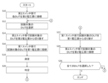
- (Operation of Test Apparatus 2) 2 shows the operation of the test apparatus 2. Note that this figure shows the operation of the test apparatus 2 relating to the measurement of the constant voltage generation current measurement section 20.
- the test apparatus 2 may test each device under test 10 by performing the processes of steps S10 to S26. In this operation, the first voltage source 201 and the second voltage source may continue to output voltages.
- the second switch section 24 connects the second voltage source 23 to the connection terminal 101 of at least one other device under test 10 (each device under test 10 is used as an example in this embodiment) that is different from the device under test 10 being tested. This allows a second voltage (a voltage having the same magnitude as the first voltage as an example in this embodiment) to be output to the connection terminal 101 of each device under test 10.
Landscapes
- Engineering & Computer Science (AREA)
- Physics & Mathematics (AREA)
- General Physics & Mathematics (AREA)
- General Engineering & Computer Science (AREA)
- Environmental & Geological Engineering (AREA)
- Computer Hardware Design (AREA)
- Microelectronics & Electronic Packaging (AREA)
- Health & Medical Sciences (AREA)
- Toxicology (AREA)
- Testing Of Individual Semiconductor Devices (AREA)
- Testing Electric Properties And Detecting Electric Faults (AREA)
- Tests Of Electronic Circuits (AREA)
Abstract
Priority Applications (5)
| Application Number | Priority Date | Filing Date | Title |
|---|---|---|---|
| KR1020257042130A KR20260012766A (ko) | 2023-08-22 | 2023-08-22 | 시험 장치 및 시험 방법 |
| CN202380098510.4A CN121152976A (zh) | 2023-08-22 | 2023-08-22 | 试验装置及试验方法 |
| PCT/JP2023/030205 WO2025041281A1 (fr) | 2023-08-22 | 2023-08-22 | Appareil de test et procédé de test |
| TW113119647A TWI914817B (zh) | 2023-08-22 | 2024-05-28 | 試驗裝置及試驗方法 |
| US19/402,994 US20260079197A1 (en) | 2023-08-22 | 2025-11-27 | Test apparatus and test method |
Applications Claiming Priority (1)
| Application Number | Priority Date | Filing Date | Title |
|---|---|---|---|
| PCT/JP2023/030205 WO2025041281A1 (fr) | 2023-08-22 | 2023-08-22 | Appareil de test et procédé de test |
Related Child Applications (1)
| Application Number | Title | Priority Date | Filing Date |
|---|---|---|---|
| US19/402,994 Continuation US20260079197A1 (en) | 2023-08-22 | 2025-11-27 | Test apparatus and test method |
Publications (1)
| Publication Number | Publication Date |
|---|---|
| WO2025041281A1 true WO2025041281A1 (fr) | 2025-02-27 |
Family
ID=94731695
Family Applications (1)
| Application Number | Title | Priority Date | Filing Date |
|---|---|---|---|
| PCT/JP2023/030205 Pending WO2025041281A1 (fr) | 2023-08-22 | 2023-08-22 | Appareil de test et procédé de test |
Country Status (4)
| Country | Link |
|---|---|
| US (1) | US20260079197A1 (fr) |
| KR (1) | KR20260012766A (fr) |
| CN (1) | CN121152976A (fr) |
| WO (1) | WO2025041281A1 (fr) |
Citations (7)
| Publication number | Priority date | Publication date | Assignee | Title |
|---|---|---|---|---|
| JP2001041997A (ja) * | 1999-07-30 | 2001-02-16 | Advantest Corp | 電源電流測定装置 |
| JP2001242222A (ja) * | 2000-02-29 | 2001-09-07 | Ando Electric Co Ltd | テストボード試験装置、及びテストボード試験方法 |
| JP2002040098A (ja) * | 2000-07-24 | 2002-02-06 | Advantest Corp | 試験装置 |
| JP2005516226A (ja) * | 2002-01-30 | 2005-06-02 | フォームファクター,インコーポレイテッド | 被テスト集積回路用の予測適応電源 |
| JP2009025129A (ja) * | 2007-07-19 | 2009-02-05 | Yokogawa Electric Corp | 信号選択装置及び半導体試験装置 |
| WO2010029597A1 (fr) * | 2008-09-10 | 2010-03-18 | 株式会社アドバンテスト | Testeur et système de circuit |
| US20130214616A1 (en) * | 2012-02-21 | 2013-08-22 | Texas Instruments Incorporated | Transmission line pulsing |
Family Cites Families (2)
| Publication number | Priority date | Publication date | Assignee | Title |
|---|---|---|---|---|
| JP2005300495A (ja) | 2004-04-16 | 2005-10-27 | Agilent Technol Inc | 半導体特性測定装置および接続装置 |
| JP2010190768A (ja) | 2009-02-19 | 2010-09-02 | Yokogawa Electric Corp | 半導体試験装置 |
-
2023
- 2023-08-22 KR KR1020257042130A patent/KR20260012766A/ko active Pending
- 2023-08-22 WO PCT/JP2023/030205 patent/WO2025041281A1/fr active Pending
- 2023-08-22 CN CN202380098510.4A patent/CN121152976A/zh active Pending
-
2025
- 2025-11-27 US US19/402,994 patent/US20260079197A1/en active Pending
Patent Citations (7)
| Publication number | Priority date | Publication date | Assignee | Title |
|---|---|---|---|---|
| JP2001041997A (ja) * | 1999-07-30 | 2001-02-16 | Advantest Corp | 電源電流測定装置 |
| JP2001242222A (ja) * | 2000-02-29 | 2001-09-07 | Ando Electric Co Ltd | テストボード試験装置、及びテストボード試験方法 |
| JP2002040098A (ja) * | 2000-07-24 | 2002-02-06 | Advantest Corp | 試験装置 |
| JP2005516226A (ja) * | 2002-01-30 | 2005-06-02 | フォームファクター,インコーポレイテッド | 被テスト集積回路用の予測適応電源 |
| JP2009025129A (ja) * | 2007-07-19 | 2009-02-05 | Yokogawa Electric Corp | 信号選択装置及び半導体試験装置 |
| WO2010029597A1 (fr) * | 2008-09-10 | 2010-03-18 | 株式会社アドバンテスト | Testeur et système de circuit |
| US20130214616A1 (en) * | 2012-02-21 | 2013-08-22 | Texas Instruments Incorporated | Transmission line pulsing |
Also Published As
| Publication number | Publication date |
|---|---|
| CN121152976A (zh) | 2025-12-16 |
| TW202509506A (zh) | 2025-03-01 |
| US20260079197A1 (en) | 2026-03-19 |
| KR20260012766A (ko) | 2026-01-27 |
Similar Documents
| Publication | Publication Date | Title |
|---|---|---|
| KR101489542B1 (ko) | 레거시 테스트 시스템의 동작 에뮬레이팅 | |
| US7818137B2 (en) | Characterization circuit for fast determination of device capacitance variation | |
| US9746520B2 (en) | Systems and methods mitigating temperature dependence of circuitry in electronic devices | |
| JPS60100065A (ja) | 電子回路の自動化テスト中にプログラムしたテスト信号を印加すると共にモニタする方法及び装置 | |
| KR20180137945A (ko) | 피시험 디바이스를 테스트하기 위한 프로세서 기반의 계측 방법 및 이를 이용한 계측 장치 | |
| JPH065261B2 (ja) | 電子デバイス又は回路テスト方法及び装置 | |
| EP1039389B1 (fr) | Méthode et dispositif pour l'apprentissage progressif des erreurs sources de tests dans le but de réduire le nombre total de mesures de test nécessaire en temps réel | |
| JP2539897B2 (ja) | 漏れ電流試験装置 | |
| JP2001099900A (ja) | 半導体集積回路の検査装置及びその検査方法並びにその検査プログラムを記録した記憶媒体 | |
| US4862069A (en) | Method of in-circuit testing | |
| CN111220901B (zh) | 运放测试系统和方法 | |
| WO2025041281A1 (fr) | Appareil de test et procédé de test | |
| US11067623B2 (en) | Test system and method of operating the same | |
| CN107436379B (zh) | 用于测试模拟信号的系统 | |
| TWI914817B (zh) | 試驗裝置及試驗方法 | |
| JP2000165244A (ja) | 半導体集積回路装置 | |
| US20250216447A1 (en) | Procedure for making on-die-parametric measurements of circuit devices | |
| EP4653882A1 (fr) | Procédé de détermination d'au moins une résistance de contact parmi une première résistance de contact et une seconde résistance de contact d'une connexion kelvin à deux fils | |
| JPS6329277A (ja) | 論理集積回路の試験装置 | |
| JPH07183346A (ja) | 半導体テスト装置 | |
| JP4214361B2 (ja) | Ic試験装置及びその出力信号のタイミング調整方法 | |
| JPH11142489A (ja) | Lsi検査方法 | |
| JPS5951369A (ja) | 自動特性測定装置 | |
| JPH09101330A (ja) | プルアップ抵抗及びプルダウン抵抗の自動試験器 | |
| JPH04190175A (ja) | Ic試験装置 |
Legal Events
| Date | Code | Title | Description |
|---|---|---|---|
| 121 | Ep: the epo has been informed by wipo that ep was designated in this application |
Ref document number: 23949742 Country of ref document: EP Kind code of ref document: A1 |
|
| ENP | Entry into the national phase |
Ref document number: 1020257042130 Country of ref document: KR Free format text: ST27 STATUS EVENT CODE: A-0-1-A10-A15-NAP-PA0105 (AS PROVIDED BY THE NATIONAL OFFICE) |
|
| WWE | Wipo information: entry into national phase |
Ref document number: 1020257042130 Country of ref document: KR |
|
| WWP | Wipo information: published in national office |
Ref document number: 1020257042130 Country of ref document: KR |
|
| NENP | Non-entry into the national phase |
Ref country code: DE |