WO2025041212A1 - Club de golf, unité amovible d'élément de transmission de vibrations, unité amovible de corps émetteur de son de type diapason, unité amovible d'élément de renforcement, système d'entraînement au golf, poignée de club de golf, et terminal mobile portable - Google Patents
Club de golf, unité amovible d'élément de transmission de vibrations, unité amovible de corps émetteur de son de type diapason, unité amovible d'élément de renforcement, système d'entraînement au golf, poignée de club de golf, et terminal mobile portable Download PDFInfo
- Publication number
- WO2025041212A1 WO2025041212A1 PCT/JP2023/029907 JP2023029907W WO2025041212A1 WO 2025041212 A1 WO2025041212 A1 WO 2025041212A1 JP 2023029907 W JP2023029907 W JP 2023029907W WO 2025041212 A1 WO2025041212 A1 WO 2025041212A1
- Authority
- WO
- WIPO (PCT)
- Prior art keywords
- golf club
- shaft
- hosel
- grip
- vibration transmission
- Prior art date
- Legal status (The legal status is an assumption and is not a legal conclusion. Google has not performed a legal analysis and makes no representation as to the accuracy of the status listed.)
- Pending
Links
Images


Classifications
-
- A—HUMAN NECESSITIES
- A63—SPORTS; GAMES; AMUSEMENTS
- A63B—APPARATUS FOR PHYSICAL TRAINING, GYMNASTICS, SWIMMING, CLIMBING, OR FENCING; BALL GAMES; TRAINING EQUIPMENT
- A63B53/00—Golf clubs
- A63B53/08—Golf clubs with special arrangements for obtaining a variable impact
-
- A—HUMAN NECESSITIES
- A63—SPORTS; GAMES; AMUSEMENTS
- A63B—APPARATUS FOR PHYSICAL TRAINING, GYMNASTICS, SWIMMING, CLIMBING, OR FENCING; BALL GAMES; TRAINING EQUIPMENT
- A63B60/00—Details or accessories of golf clubs, bats, rackets or the like
- A63B60/42—Devices for measuring, verifying, correcting or customising the inherent characteristics of golf clubs, bats, rackets or the like, e.g. measuring the maximum torque a batting shaft can withstand
-
- A—HUMAN NECESSITIES
- A63—SPORTS; GAMES; AMUSEMENTS
- A63B—APPARATUS FOR PHYSICAL TRAINING, GYMNASTICS, SWIMMING, CLIMBING, OR FENCING; BALL GAMES; TRAINING EQUIPMENT
- A63B69/00—Training appliances or apparatus for special sports
- A63B69/36—Training appliances or apparatus for special sports for golf
Definitions
- the present invention relates to a golf club for hitting a golf ball, a detachable unit for a vibration transmission member, a detachable unit for a tuning fork-type sound generating body, a detachable unit for a reinforcing member, a golf practice system using a golf club, a golf club grip, and a portable mobile terminal.
- a shaft with a grip is connected to the head by a hosel.
- the hosel is removably fixed to the shaft or head, for example. This structure makes it easy to replace the shaft or head (see Patent Documents 1 and 2).
- a golf club with a hosel In the case of a golf club with a hosel, the vibrations generated in the head when hitting a golf ball are transmitted via the shaft to the palm of the user (golfer) holding the grip, and are recognized as part of the feel of the golf club.
- the hosel interposed between the shaft and the head can act to inhibit the transmission of such vibrations. Therefore, a golf club with a hosel has the problem that it is difficult to obtain a good feel when hitting compared to a golf club without a hosel.
- the feel of the hit refers to the feeling or shot that the user has when hitting a golf ball.
- a typical hit feel includes not only physical vibrations, but also the comfortableness (feeling) of the sensory operation, such as the feel of the hit, the sense of moderation, and the sense of accomplishment.
- One of the objectives of this case was devised in light of the above-mentioned problems, and is to provide a golf club, a detachable unit for a vibration transmission member, a detachable unit for a tuning fork-type sounding body, a detachable unit for a reinforcing member, a golf practice system, a golf club grip, and a portable mobile terminal that are capable of improving the feel of the impact.
- another objective of this case is to achieve effects that are derived from the various configurations shown in the "Form for carrying out the invention" described below and that cannot be obtained with conventional technology.
- the disclosed golf club solves at least a part of the above problems.
- the disclosed golf club includes a head having a striking surface for striking a golf ball, a shaft formed in an axial shape, a hosel connecting one end of the shaft to the head, the grip is provided at the other end of the shaft and is held by a user, the hosel is formed integrally with the head and the shaft in a non-replaceable state, the shaft has a first hollow cavity therein, the grip has a second hollow cavity therein that communicates with the first cavity, the grip is formed integrally with the shaft, is formed in an elongated shape, has one end fixed to the hosel, is built into the first cavity and the second cavity, and comprises a vibration transmission member that transmits vibrations generated on the striking surface to the grip, and an attachment member that is provided inside the second cavity and connects the other end of the vibration transmission member to the grip.
- the disclosed golf club includes a head having a striking surface for striking a golf ball, a shaft formed in an axial shape, a hosel connecting one end of the shaft to the head, and a grip attached to the other end of the shaft and held by a user, the hosel being formed integrally with the head and the shaft in an irreplaceable state, the shaft having a first hollow cavity therein, the grip having a second hollow cavity therein communicating with the first cavity, the grip being formed integrally with the shaft, one end of the grip being fixed to the hosel, and being built into at least the first cavity, and including a tuning fork-type sounding body that vibrates in response to the impact of striking the golf ball with the striking surface to produce sound.
- the disclosed detachable unit of a vibration transmission member includes a head having a striking surface for striking a golf ball, a shaft formed in an axial shape, a hosel connecting one end of the shaft to the head, and a grip provided on the other end of the shaft and held by a user.
- the detachable unit is detachably attached to a golf club, the shaft having a first hollow cavity therein and the grip having a second hollow cavity therein communicating with the first hollow cavity, the main body being built in the first cavity and the second cavity, extending in the axial direction of the shaft, having a cylindrical shape that follows the inner circumferential shape of the first cavity and the second cavity, and having a hollow portion therein; and a vibration transmission member that is formed in an elongated shape, has one end fixed to a lower end of the main body, is built in the hollow portion, and transmits vibrations generated at the striking surface to the grip.
- the disclosed detachable unit of a vibration transmission member includes a head having a striking surface for striking a golf ball, a shaft formed in an axial shape, and a grip provided at the other end of the shaft and held by a user, and is detachably attached to a golf club, the shaft having a first hollow cavity therein and the grip having a second hollow cavity therein communicating with the first hollow cavity, the main body being built into the first hollow cavity and the second hollow cavity, extending in the axial direction of the shaft, having a cylindrical shape that follows the inner circumferential shape of the first hollow cavity and the second hollow cavity, and having a hollow portion therein, and a vibration transmission member that is formed in an elongated shape, has one end fixed to a lower end of the main body, is built into the hollow cavity, and transmits vibrations generated at the striking surface to the grip.
- the removable unit of the disclosed tuning fork-type sounding body includes a head having a striking surface for striking a golf ball, a shaft formed in an axial shape, a hosel connecting one end of the shaft to the head, and a grip provided on the other end of the shaft and held by a user.
- the shaft is removably attached to a golf club having a first hollow portion formed therein, the main body being built into the first hollow portion, extending in the axial direction of the shaft, having a cylindrical shape that follows the inner circumferential shape of the first hollow portion, and having a hollow portion formed therein; and a tuning fork-type sounding body that is formed in an elongated shape, has one end fixed to a lower end of the main body, is built into the hollow portion, and vibrates due to the impact of striking the golf ball with the striking surface to produce sound.
- the removable unit of the disclosed tuning fork-type sounding body comprises a head having a striking surface for striking a golf ball, a shaft formed in an axial shape, and a grip provided at the other end of the shaft and held by a user.
- the shaft is removably attached to a golf club having a first hollow portion formed therein, the shaft is built into the first hollow portion, the main body extends in the axial direction of the shaft, has a cylindrical shape that follows the inner circumferential shape of the first hollow portion, and has a hollow portion formed therein; and a tuning fork-type sounding body that is formed in an elongated shape, has one end fixed to a lower end of the main body, is built into the hollow portion, and vibrates due to the impact of striking the golf ball with the striking surface to produce sound.
- the removable unit of the disclosed reinforcing member includes a head having a striking surface for striking a golf ball, a shaft formed in an axial shape, a hosel connecting one end of the shaft to the head, and a grip provided on the other end of the shaft to be held by a user.
- the shaft is removably attached to a golf club having a first hollow portion formed therein, the main body being incorporated into the first hollow portion, extending in the axial direction of the shaft and having a cylindrical shape that follows the inner shape of the first hollow portion, and having a hollow portion formed therein, and a reinforcing member incorporated into the hollow portion to reinforce the strength of the shaft.
- the removable unit of the disclosed reinforcing member comprises a head having a striking surface for striking a golf ball, a shaft formed in an axial shape, and a grip provided on the other end of the shaft and held by a user, and is removably attached to a golf club having a first hollow portion formed therein, the shaft being incorporated into the first hollow portion, a main body portion extending in the axial direction of the shaft and having a cylindrical shape that follows the inner circumferential shape of the first hollow portion, and having a hollow portion formed therein, and a reinforcing member incorporated into the hollow portion to reinforce the strength of the shaft.
- the disclosed golf practice system includes a cup provided on the rolling surface (golf ball rolling surface) of a golf ball hit by the golf club described in (1) or (2), a hitting area separated from the cup and having the golf ball rolling surface, a rod-shaped pin that is inserted and removed from the cup and serves as a marker for the cup, a first illuminator attached to the pin and irradiates a guide laser beam showing a straight line from the pin toward the hitting area, a first light receiver attached to the golf club and capable of receiving the guide laser beam from the first illuminator, a second illuminator attached to the golf club and irradiates a guide sub-laser beam from the golf club toward the pin, a second light receiver attached to the pin and capable of receiving the guide sub-laser beam from the second illuminator, and an indicator that receives the guide laser beam with the first light receiver and displays the fact that the guide sub-laser beam is received by the second light receiver.
- the disclosed golf practice system includes a golf practice machine having a cup provided on the rolling surface (golf ball rolling surface) of a golf ball hit by the golf club described in (1) or (2), and a hitting area separated from the cup and having the golf ball rolling surface, and a user standing in the hitting area hits the golf ball with the golf club toward the cup, a pin unit having a first photographing means attached to a rod-shaped pin marking the cup and photographing an image from the pin toward the hitting area, a second transmitting device that transmits the first image data photographed by the first photographing means to the outside, and a first illuminator that irradiates a guide laser light from the pin toward the hitting area, a vibration detection means attached to the golf club used by the user in the hitting area and detecting vibration information related to the vibration transmitted by the vibration transmission member, a second detection means built into the head and detecting hitting information related to the hitting of the golf ball, and
- the club unit includes a second image capturing means for capturing an image from the head toward the front, a second
- the disclosed golf club grip is a golf club that includes a shaft formed in an axial shape, a head provided at one end of the shaft and having a striking surface for striking a golf ball, and a grip provided at the other end of the shaft and held by a user, and the grip is provided with a grip member made of a mesh member formed from resin fibers in a net shape.
- the disclosed golf club is the golf club described in (1) above, wherein the head has a weight member for changing the position of the center of gravity of the head.
- the disclosed golf club is the golf club of (12) above, wherein the weight member is provided inside a hollow cylindrical recess formed in an upper surface of the head, and the golf club is equipped with a drive source for moving the weight member, and a control unit for controlling the drive source so that the drive source rotates and moves the weight member along the inner surface of the recess.
- the disclosed golf club is the golf club of (12) above, wherein the weight member is provided inside a linear recess formed in an upper surface of the head, and the golf club is equipped with a drive source for moving the weight member, and a control unit for controlling the drive source so that the drive source slides the weight member along the inner surface of the recess.
- the disclosed portable mobile terminal is a portable mobile terminal that transmits and receives control signals between the control unit of the golf club described in (13) or (14) above, and is equipped with an input unit that inputs an instruction to move the weight member to a desired position, and a display unit that monitors and displays the position of the weight member moved in response to the movement instruction from the input unit.
- the disclosed golf club by providing a vibration transmission member in the hosel, vibrations generated when hitting a golf ball can be efficiently transmitted to the shaft, improving the hitting feel.
- the disclosed golf club has a tuning fork-type sounding body that vibrates and emits sound when the striking surface strikes the golf ball, so that the impact sound produced when striking the golf ball can be emphasized, thereby improving the hitting feel when striking the golf ball.
- the vibration transmission member can be easily attached to and detached from the golf club.
- the tuning fork type sounding body can be easily attached to and detached from the golf club.
- the disclosed detachable unit of the reinforcing member can reinforce the shaft of the golf club.
- the detachable unit of the vibration transmission member and the detachable unit of the tuning fork type sounding body can also reinforce the shaft of the golf club.
- the effect of practice can be improved.
- the monitor information includes vibration information related to the vibration of the vibration transmission member
- the correlation between the vibration information and the hitting information (other monitor information) e.g., the relationship between the vibration and the quality of the hit
- the vibration information can be visualized using numerical values, graphs, etc., or the vibration information can be accumulated as big data.
- the grip member is made of a mesh material formed from resin fibers in a net shape, so vibrations from the shaft tend to be easily transmitted to the user's hand through the grip member, thereby improving the hitting feel. Furthermore, according to the disclosed portable mobile terminal, the position of the weight member can be adjusted simply and visually.
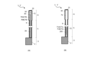
- FIG. 1A is a perspective view illustrating a golf club as a first embodiment
- FIG. 1B is a perspective view for explaining a modified example of a hosel in the golf club as the first embodiment
- 1A to 1C are perspective views illustrating different types of golf club heads.
- 11A to 11F are perspective views illustrating modified examples of the connection between the hosel and the shaft of a golf club.
- 11A to 11D are perspective views for explaining modified examples of the hosel of the golf club.
- 1A to 1C are cross-sectional views illustrating the internal structure of the golf club shown in FIG. 1A to 1C are cross-sectional views illustrating the internal structure of the golf club shown in FIG.
- FIGS. 7A and 7B are cross-sectional views for explaining a modified example of the internal structure of the golf club shown in FIG. 7A and 7B are cross-sectional views for explaining a modified example of the internal structure of the golf club shown in FIGS. 7A and 7B.
- 11A to 11C are cross-sectional views illustrating modified examples of the internal structure of a golf club.
- 9A and 9B are cross-sectional views for explaining modified examples of the internal structure of the golf club shown in FIGS. 9B and 9C.
- 10A and 10B are cross-sectional views for explaining a modified example of the internal structure of the golf club shown in FIG. 11A and 11B are cross-sectional views for explaining a modified example of the internal structure of the golf club shown in FIGS.
- 13A to 13C are explanatory diagrams illustrating modified examples of the internal structure of a golf club.
- 11A and 11B are cross-sectional views illustrating modified examples of the vibration transmitting member.
- 13A to 13G are explanatory diagrams illustrating modified examples of the vibration transmitting member.
- 11A to 11F are cross-sectional views illustrating modified examples of the vibration transmitting member.
- 11A and 11B are cross-sectional views illustrating modified examples of the vibration transmitting member.
- 11A to 11D are cross-sectional views for explaining modified examples of the golf club.
- 13A to 13E are explanatory diagrams illustrating modified examples of a hosel of a golf club.
- 11A to 11E are cross-sectional views illustrating modified examples of the vibration transmitting member.
- FIG. 11 is a cross-sectional view for explaining a modified example of the internal structure of the golf club.
- 13A and 13B are perspective views for explaining modified examples of the golf club head.
- FIG. 13 is a perspective view for explaining a modified example of a golf club.
- 24 is an explanatory diagram for explaining a modified example of the golf club shown in FIG. 23.
- 13A and 13B are explanatory diagrams for explaining modified examples of golf clubs.
- 1 is a block diagram for explaining a configuration of a golf practice system to which a golf club is applied.
- 13A and 13B are explanatory diagrams for explaining modified examples of golf clubs.
- 13A to 13E are explanatory diagrams for explaining modified examples of the golf club.
- 13A to 13D are explanatory diagrams for explaining modified examples of the golf club.
- 13A to 13D are explanatory diagrams for explaining modified examples of the golf club.
- 13A to 13F are explanatory diagrams for explaining a detachable unit of a vibration transmission member/tuning fork type sound generating body.
- 13A to 13E are explanatory diagrams for explaining modified examples of the golf club.
- FIG. 25 is a processing block diagram relating to the golf club of FIGS. 23 and 24.
- FIG. 23 is a processing block diagram relating to the golf club of FIG. 22.
- 13A and 13B are explanatory diagrams for explaining modified examples of golf clubs.
- FIG. 36 is a processing block diagram relating to the golf club of FIG. 35.
- 13A to 13C are explanatory diagrams for explaining modified examples of the golf club.
- 13A and 13B are explanatory diagrams of modified examples of the detachable unit.
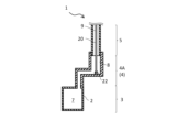
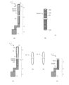
- Structure 1A is a perspective view illustrating a golf club 1 (putter) according to a first embodiment.
- the golf club 1 includes a head 3, a hosel 4, a shaft 5, and a grip 6.
- a striking surface 2 (face) for striking a golf ball is provided on the side of the head 3.
- the hosel 4 is a joint member that connects the lower end (one end) of the shaft 5 to the head 3. By connecting the lower end of the shaft 5 to the head 3 via the hosel 4, it is easier to connect the lower end of the shaft 5 to the head 3 than in a structure without a hosel.
- the shape of the hosel 4 is not particularly limited, and may be any well-known shape. In the golf club 1 of FIG.
- hosel 4 As an example of the hosel 4, a crank-shaped hosel 4A having a first bent portion 4F and a second bent portion 4R (two bent portions) at the intermediate portion between the upper end 4U and the lower end 4D is provided.
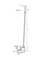
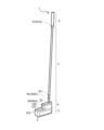
- a flat hosel 4B that extends in a plane direction parallel to the striking surface 2 and is formed in a rectangular flat plate shape having a certain thickness is provided.
- hosel 4" is used as a general term for hosels of various shapes, except when it is necessary to distinguish them.
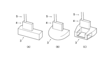
- FIGS. 2(A)-(C) are perspective views illustrating various types of putter heads 3.
- the shape of the head 3 may be a pin type as shown in FIG. 2(A), a mallet type as shown in FIG. 2(B), or a neo-mallet type as shown in FIG. 2(C).
- FIGS. 2(A)-(C) show a golf club 1 having a flat hosel 4B as shown in FIG. 1(B) as an example, but the shape of the hosel 4 may be any, including the crank-shaped hosel 4A in FIG. 1(A).
- the shaft 5 is formed in an axial shape (a long, thin rod), and one end (the lower end in FIG. 1) is connected to the head 3 via the hosel 4.
- the shape of the lower end of the shaft 5 fixed to the hosel 4 may be straight as shown in FIGS. 1(A) and (B), or may be crank-shaped (see FIG. 4(A) below) with two or more bends and with the upper end positioned further forward than the lower end, or may be bent (curved).
- the direction in which the striking surface 2 faces when using the golf club 1 is referred to as the "forward" direction
- the opposite side is referred to as the "rearward" direction.
- the cross-sectional shape of the shaft 5 may be circular, elliptical, or polygonal.
- a grip 6, which is the part to be held by the user, is provided at the other end (the upper end in FIG. 1) of the shaft 5.
- the cross-sectional shape of the grip 6 may be circular, elliptical, or polygonal.
- the hosel 4 is formed integrally with the head 3 and the shaft 5 in a non-replaceable state, for example.
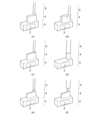
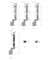
- Figures 3(A) to 3(F) are perspective views for explaining several specific examples of the connection form between the rectangular flat hosel 4B (hosel 4) and the shaft 5.
- the shaft 5 may be connected to the end face of the hosel 4 as shown in Figure 3(A), or may be connected to the plate surface of the hosel 4 as shown in Figure 3(B).
- the thickness of the hosel 4 (dimension in the plate thickness direction) can be set regardless of the thickness of the shaft 5.
- the cross-sectional area of the lower end of the shaft 5 may be processed to be smaller as shown in Figure 3(C).
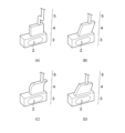
- the hosel 4 may be provided detachably with respect to the head 3 and the shaft 5.
- the width dimension of the hosel 4 when viewed from the front can also be set independently of the thickness of the shaft 5.
- the width dimension of the hosel 4 may be set to a dimension approximately equal to the thickness of the shaft 5.
- the hosel 4 may be formed so that the width dimension is smaller only at the upper end connected to the shaft 5.
- the width dimension of the upper end of the hosel 4 may be set to a dimension approximately equal to the thickness of the shaft 5.
- the upper end of the hosel 4 may be made thinner than the shaft 5.
- the orientation of the hosel 4 fixed to the head 3 is set so that it extends in a planar direction parallel to the striking surface 2.
- the hosel 4 may be arranged parallel to the striking surface 2.
- the flat hosel 4 may be arranged tilted at an angle (for example, with the upper part tilted toward the striking surface 2).
- the shape of the lower end of the shaft 5 fixed to the hosel 4 may be crank-shaped, as shown in FIG. 4(A), or straight, or bent (curved) in shape.
- the hosel 4 may be formed in a flat plate shape or a curved plate shape. If it is formed in a flat plate shape, it may be formed in a rectangular plate shape as shown in FIG. 4(A) or a polygonal (triangular or pentagonal) plate shape. If it is formed in a curved plate shape, it may be curved so that the side closer to the striking surface 2 is on the inside in a longitudinal cross section perpendicular to the striking surface 2 as shown in FIG. 4(C), or it may be curved so that the side closer to the striking surface 2 is on the outside.
- the hosel 4 may be formed in a flat irregular quadrilateral shape that imitates the side shape of a horseshoe as shown in FIG. 4(D).
- the hosel 4 and head 3 may be arranged so as to be flush with the striking surface 2 (forming the same plane) as shown in FIG. 1(B), or may be arranged so as to be non-flush with the striking surface 2 (the hosel 4 is arranged behind the striking surface 2) as shown in FIG. 3(A)-(F). It goes without saying that even in the various examples of how the hosel 4 and head 3 are arranged, such as FIG. 3(A)-(F), the hosel 4 and head 3 may be arranged so as to be flush with the striking surface 2 as shown in FIG. 1(B).
- hosel 4, shaft 5, and grip 6 included in the golf club 1 are each formed to be hollow (having a cavity inside).
- the head 3 and the hosel 4 may each be formed to be hollow (having a cavity inside) or solid (having no cavity inside).
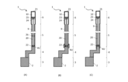
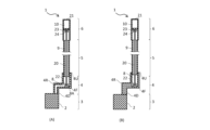
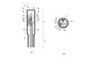
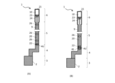
- 5(A), (B), and (C) are cross-sectional views showing the longitudinal section of the golf club 1 in FIG. 1(A), and show an example in which the shaft 5 and the grip 6 are each hollow, and the crank-shaped hosel 4A (hosel 4) and the shaft 5 are each solid.
- the golf clubs 1 shown in Figures 5(A), (B), and (C) are the same except for the manner in which the hosel 4 and shaft 5 are connected. Specifically, in the golf club 1 of Figure 5(A), the upper end of the hosel 4 and the lower end of the shaft 5 are butted together and connected. In the golf club 1 of Figure 5(B), the inner circumference of the upper end of the hosel 4 is set to be larger than the outer circumference of the lower end of the shaft 5, and the lower end of the shaft 5 is inserted into the upper end of the hosel 4 and connected.
- the outer circumference of the upper end of the hosel 4 is set to be smaller than the inner circumference of the lower end of the shaft 5, and the upper end of the hosel 4 is inserted into the lower end of the shaft 5 and connected.
- the shaft 5 has a hollow shaft cavity 9 (first cavity) therein, and the grip 6 has a hollow grip cavity 10 (second cavity) therein that communicates with the shaft cavity 9. Both the upper and lower ends of the shaft 5 are open. The upper end of the grip 6 is closed by a grip upper end plate 21 that forms the grip end, and the lower end is open. The shaft cavity 9 and the grip cavity 10 communicate with each other.
- the head 3 and the hosel 4 are formed of a solid material having a compact cross section.
- a vibration transmission member 20 is built into the golf club 1.
- the vibration transmission member 20 is a member that transmits vibrations generated on the striking surface 2 to the grip 6.
- the vibration transmission member 20 is formed in a long shape and is provided inside the shaft cavity 9 and the grip cavity 10.
- Specific examples of the vibration transmission member 20 include wires (e.g., steel wires and piano wires), strings (e.g., strings made by weaving various fibers, wide belts, and mesh-like belts), rod members (e.g., rod members made of rod-shaped metal or wood), linear elastic members (e.g., linear elastic members made of rubber or resin), and long coil springs.
- fibers include cellulose, nanocellulose, and cellulose nanofibers.
- 5A, 5B and 5C show an example in which the vibration transmission member 20 is formed of a rod member.
- the vibration transmission member 20 is directly fixed to the hosel 4 via a fixing device 22. Meanwhile, the other end of the vibration transmission member 20 (the upper end in Figs. 5A, 5B, and 5C) is attached to the inner peripheral surface of the grip 6 via an inner grip plate 23 and an inner grip fixing device 24 (attaching member).
- the fixing device 22 is, for example, a member attached to the upper end 4U of the hosel 4, and may have any structure as long as it can fix the lower end of the vibration transmission member 20. In this case, the vibration transmission member 20 is arranged in a straight line between the fixing device 22 and the inner grip fixing device 24.
- a mass member 26 that serves as a weight for amplifying vibration may be attached to the vibration transmission member 20, as shown by the dashed line in Fig. 5A.
- the position of the mass member 26 may be fixed relative to the vibration transmission member 20, or may be movable (the fixing position may be adjustable). In addition, for example, the mass member 26 may be added according to the user's preference.
- the mass member 26 may be attached to any golf club 1, not limited to the golf club 1 shown in FIG. 5(A).
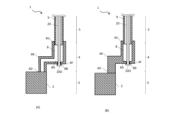
- the golf clubs 1 shown in Figures 6(A), (B), and (C) are the same as the golf clubs 1 shown in Figures 5(A), (B), and (C), except that they have a flat hosel 4B as the hosel 4. That is, in the golf clubs 1 shown in Figures 6(A), (B), and (C), one end of the vibration transmission member 20 disposed inside the shaft cavity 9 and the grip cavity 10 is fixed to the flat hosel 4B via a fixing device 22.
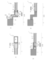
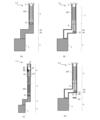
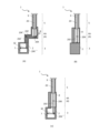
- FIG. 7A and 7B show an example of the configuration of a golf club 1 in which the inside of a crank-shaped hosel 4A (hosel 4) is formed to be hollow.
- a hosel cavity 8 (third cavity) is provided inside the hosel 4.
- the hosel 4 shown in Fig. 7A is provided with the hosel cavity 8 formed to communicate between the upper end 4U and the lower end 4D.
- the hosel cavity 8 has a crank shape having two bent portions corresponding to the two bent portions 4F, 4R of the crank-shaped hosel 4A.
- the hosel 4 shown in FIG. 7(B) has a hosel cavity 8 in a portion of the hosel 4 located on the shaft 5 side (upper side), and the remaining portion of the hosel 4 excluding the portion on the shaft 5 side (upper side) is formed solid.
- the hosel 4 shown in FIG. 7(B) has a hosel cavity 8 from the upper end 4U to the first bend 4F, and the portion located closer to the head 3 than the first bend 4F, i.e., the portion including the second bend 4R and the lower end 4D, is formed solid.
- the hosel cavity 8 is formed in a straight line from the upper end 4U to the first bend 4F.
- FIGS 7(A) and (B) show an example in which one end of the vibration transmission member 20 is fixed to the inner peripheral surface of the hosel cavity 8 via a fixing device 22.
- the fixing device 22 is disposed at the first bend 4F on the surface 8A of the inner peripheral surface of the hosel cavity 8 that faces the upper end 4U.
- one end of the vibration transmission member 20 is fixed below the upper end 4U of the hosel 4 within the hosel cavity 8.
- vibrations generated on the striking surface of the head 3 are not only transmitted to the grip 6 via the hosel 4 and shaft 5, but also to the grip 6 via the hosel 4 and vibration transmission member 20.
- the vibration transmission member 20 into the shaft 5 and grip 6, the vibration transmission path can be increased, and vibrations generated on the striking surface of the head 3 can be efficiently transmitted to the grip 6 without attenuation. Therefore, a good hitting feel can be provided to the user, and the hitting feel can be improved compared to existing golf clubs.
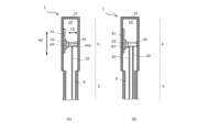
- FIG. 8(A) and (B) are modified versions of the golf club 1 shown in FIG. 7(A) and (B), and the mounting structure of the lower end (one end) of the vibration transmission member 20 is different from that of FIG. 7(A) and (B).
- a hole 8B that connects the hosel cavity 8 to the outside is provided at the first bent portion 4F, on the surface 8A of the inner circumferential surface of the hosel cavity 8 that faces the upper end 4U.
- the hole 8B is a mounting hole for the vibration transmission member 20.
- the vibration transmission member 20 is inserted into the hosel cavity 8 from the outside of the hosel 4 through the hole 8B.
- the lower end 20D of the vibration transmission member 20 is formed wider than the diameter of the hole 8B, and the lower end 20D of the vibration transmission member 20 is engaged and attached on the outside of the hole 8B.
- the grip inner plate 23 and the grip inner fixture 24 (mounting member) provided at the other end (upper end in the figure) of the vibration transmission member 20 may be provided so as to be adjustable in position in the extension direction of the grip 6.
- the grip inner plate 23 may be formed in a membrane shape that is deployed in a direction intersecting the extension direction of the grip 6 (for example, a direction perpendicular to the extension direction of the grip 6).
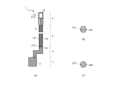
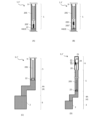
- FIGS. 9A and 9B show modified examples of the golf club 1 shown in each of the above-mentioned golf clubs 1, in which the mounting structure of the upper end (other end) of the vibration transmission member 20 is different.
- the other end (the upper end in the figure) of the vibration transmission member 20 is attached to the inner surface of the grip 6 via a grip upper end plate 21 and a grip inner fixing device 24 (mounting member).
- a motor 43 and a winding device 44 are provided at the other end (upper end in the figure) of the vibration transmission member 20.
- the motor 43 and the winding device 44 are mechanisms for making it possible to adjust the position of the other end of the vibration transmission member 20 in the extending direction of the grip 6.
- the vibration transmission member 20 is formed of a windable member, and specifically, is composed of any one of a wire, a string, a linear elastic member, and a long coil spring.
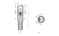
- Fig. 9(C) is a cross-sectional view of the golf club 1 taken along line X1-X1 in Fig. 9(B).
- the winding device 44 is formed of a rod-shaped body extending along the cross section of the grip 6, and a motor 43 is connected to one end of the rod-shaped body.
- a pinion 42 is rotatably attached to the motor 43.
- a rack 41 that meshes with the pinion 42 is fixed to the inner circumferential surface of the grip cavity 10.
- the pinion 42 is urged upward relative to the rack 41 by a urging member (e.g., a spring or rubber) (not shown).
- the pinion 42 moves downward along the rack 41 by rotating the motor 43 and winding up the other end of the vibration transmission member 20 with the winding device 44.
- the pinion 42 moves upward along the rack 41 by rewinding the motor 43.
- a manually operated winding device 44 may be used instead of the motor 43.
- the winding device 44 may be provided so as to be rotated from the outside using a tool such as a Phillips screwdriver or a flathead screwdriver.
- the pinion 42 moves downward along the rack 41 by manually rotating the winding device 44 to wind up the other end of the vibration transmission member 20.
- the pinion 42 moves upward along the rack 41 by rewinding the winding device 44 in the opposite direction.
- the rack and pinion may be omitted, and a mechanism for adjusting the tension of the vibration transmission member 20 may be formed by winding/releasing the other end of the vibration transmission member 20 using a motor 43 and a winding device 44.
- the golf club 1 shown in FIG. 10(A) is a modified version of the golf club 1 shown in FIG. 9(B), and has an adjustment mechanism 44A (shown by a dashed line in the figure) that adjusts the position of the vibration transmission member 20 along a transverse direction that intersects with the extension direction of the grip 6.
- the transverse direction adjustment mechanism 44A is built into the winding device 44, and includes, for example, a rack along the transverse direction, a pinion meshed with the rack, and a motor that rotates the pinion.
- the position of the other end of the vibration transmission member 20 can be adjusted along the transverse direction indicated by the arrow CX in the figure.
- the golf club 1 shown in Fig. 10(B) is another modified example of the golf club 1 shown in Fig. 9(B).
- two (plural) vibration transmission members 20, 20' are provided in parallel with respect to a set of a rack 41, a pinion 42, a motor 43, and a winding device 44.
- the other ends (upper ends in the figure) of the two vibration transmission members 20, 20' are attached in parallel with one winding device 44.
- One end (lower end, not shown) of each of the two vibration transmission members 20, 20' is attached to a fixture 22 (Fig. 5(A) etc.). In this case, one fixture 22 (Fig.
- vibrations may be transmitted to the shaft 5 and grip 6 more efficiently, allowing the user to feel accurate and delicate vibrations.
- the golf club 1 shown in Figures 11(A) and (B) is a modified version of the golf club 1 shown in Figure 10(B), and has two (multiple) sets of racks 41, 41', pinions 42, 42', motors 43, 43', and winding devices 44, 44' corresponding to two (multiple) vibration transmission members 20, 20'.
- Figure 11(B) is a cross-sectional view of the golf club 1 taken along line X2-X2 in Figure 11(A). As shown in Figure 11(B), the winding devices 44, 44' are arranged in parallel to each other.
- the golf club 1 shown in Figures 12(A) and (B) is a modified version of the golf club 1 shown in Figures 11(A) and (B), and the arrangement of the two sets of racks 41, 41', pinions 42, 42', motors 43, 43', and winding devices 44, 44' is different from that in Figures 11(A) and (B).
- the two sets of racks 41, 41', pinions 42, 42', motors 43, 43', and winding devices 44, 44' are arranged in such a manner that the winding devices 44, 44' cross each other.
- Figure 12(B) is a cross-sectional view of the golf club 1 taken along line X3-X3 in Figure 12(A).
- FIGS 13B and 13C are plan views of the upper mounting member 27U and the lower mounting member 27D, respectively, viewed from the extending direction of the vibration transmitting members 20 and 20'.
- each of the upper mounting member 27U and the lower mounting member 27D is formed of a circular plate-like member having a surface that intersects with the extension direction of the vibration transmission members 20, 20'.
- each of the upper mounting member 27U and the lower mounting member 27D is disposed in such a manner that its plate surface intersects with the extension direction of the vibration transmission members 20, 20' and is parallel to each other.
- the upper mounting member 27U and the lower mounting member 27D each have a plurality of connecting holes 28U, 28D penetrating from one surface of the plate to the other surface.
- the connecting holes 28U, 28D are connecting portions for connecting the ends of the vibration transmission members 20, 20'.
- One end of vibration transmission member 20 is connected to one connecting hole 28D in lower mounting member 27D, and one end of vibration transmission member 20' is connected to another connecting hole 28D in lower mounting member 27D.
- the other end of vibration transmission member 20 is connected to one connecting hole 28U in upper mounting member 27U, and the other end of vibration transmission member 20' is connected to another connecting hole 28U in upper mounting member 27U.
- the vibration transmission members 20, 20' can be attached to the connecting holes 28U, 28D of the upper mounting member 27U and the lower mounting member 27D, one each. Therefore, multiple vibration transmission members 20, 20' can be provided in the same number of connecting holes 28U, 28D. It is preferable that the connecting holes 28U, 28D to which the vibration transmission members 20, 20' are attached are arranged in a straight line so that the multiple vibration transmission members 20, 20' are parallel to each other. In this case, since the multiple vibration transmission members 20, 20' are arranged in a forest, it can be said that the multiple vibration transmission members 20, 20' are arranged in a harp shape.
- the upper attachment member 27U may be attached to the grip upper end plate 21 (grip end).
- the grip upper end plate 21 itself may function as the upper attachment member 27U, that is, the grip upper end plate 21 may be provided with a plurality of connection holes 28U.
- the lower mounting member 27 ⁇ /b>D may be attached to the inner peripheral surface of the hosel 4 within the hosel cavity 8 .
- the lower mounting member 27D may be combined with the winding device 44. In this case, the lower ends of the vibration transmission members 20, 20' are attached to the lower mounting member 27D, and the upper ends are attached to the winding device 44.
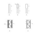
- Figures 14(A) and (B) are explanatory diagrams of modified examples of the vibration transmission member 20.
- the golf club 1 shown in Figures 14(A) and (B) differs from the golf club 1 shown in Figure 5(A) in the shape of the vibration transmission member 20, but other features are common to the golf club 1 shown in Figure 5(A).
- 14A shows a vibration transmission member 20 having a wide portion 20A in the middle in the extending direction.
- the wide portion 20A is a portion formed wider than its upper and lower portions.
- the wide portion 20A can adjust the vibration transmission characteristics of the vibration transmission member 20 and improve the hitting feel.
- ⁇ Tuning fork type> 14B shows a vibration transmission member 20 having a tuning fork shape with an upper portion split into two (U-shape).
- one in-grip fixing device 24 is provided corresponding to each of the upper ends of the bifurcated vibration transmission member 20.
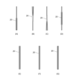
- ⁇ Tuning fork type, Y-shaped, ring type> 15A to 15G show examples of various shapes of the vibration transmission member 20.
- the vibration transmission member 20 is configured as a rod member.
- the vibration transmission member 20 shown in Fig. 15(A) has a tuning fork shape with a bifurcated (U-shaped) lower portion. In other words, it has a shape obtained by turning upside down the vibration transmission member 20 shown in Fig. 14(B).
- fixing devices 22 Fig. 5(A) etc.
- the vibration transmission member 20 shown in Figures 15(B) and (C) is Y-shaped.
- the vibration transmission member 20 in Figure 15(B) is Y-shaped with an upper portion split into two
- the vibration transmission member 20 in Figure 15(C) is Y-shaped with a lower portion split into two.
- the vibration transmission member 20 shown in Fig. 15(D) has a shape having a ring-shaped portion in the middle in the extension direction.
- the vibration transmission member 20 shown in Fig. 15(E) is formed in a ring shape as a whole, and differs from the vibration transmission member 20 shown in Fig. 15(D) in that there are no line portions on either the top or bottom.
- the vibration transmission member 20 shown in Fig. 15(F) and (G) is a modified example of the tuning fork type vibration transmission member 20 shown in Fig. 14(B) and Fig. 15(A), and is formed in a U-shape as a whole.
- the vibration transmission members 20 shown in Figures 15(A) to (G) can provide the user with a better hitting feel by adjusting the vibration transmission characteristics of the vibration transmission member 20 or emphasizing the vibration depending on the shape.
- the shapes of the vibration transmission members 20 shown in Figures 15(A) to (G) are examples and are not limited to those shown.
- the entire vibration transmission member 20 may be formed in a V-shape.
- the upper or lower portion of the vibration transmission member 20 may be branched into three or more branches.
- the golf club 1 shown in Figures 16(A) and (B) is an example in which the vibration transmission member 20 is made of a wire or string.
- the wire is, for example, a steel wire or a piano wire.
- the string includes various shapes of string-like bodies, such as a string made by weaving various fibers, a wide belt string, a mesh-like belt string, and a membrane-like belt string.
- the vibration transmission member 20 shown in Figure 16(A) the lower end of a single wire or string constituting the vibration transmission member 20 is fixed to a fixture 22, and the upper end thereof is fixed to a fixture 24 inside the grip.
- the vibration transmission member 20 shown in Fig. 16(B) has a plurality of sound-producing bodies 20S attached along the extending direction of the wire or string.
- Each sound-producing body 20S is an object that produces a sound by the vibration of the vibration transmission member 20.
- Examples of the sound-producing body 20S include bells, beads, pieces of wood, pieces of metal, and vibrating plates.
- structures that produce sound using a vibration transmission member 20 made of wire or string are not limited to structures that use a sound-producing body 20S, and can also include structures (such as a mukkuri or mouth harp type) in which the sound generated by the vibration of the vibration transmission member 20 resonates within the shaft hollow portion 9 and the grip hollow portion 10.
- the golf club 1 shown in FIG. 16(C) is an example in which the vibration transmission member 20 is configured as a chain.
- a chain is a chain member in which ring-shaped parts are linearly connected.
- the ring-shaped parts that make up the chain may have any known shape or connection form. Examples of the types (shapes) of chains include chain-shaped, armor-shaped, snake-shaped, and scale-shaped.
- ⁇ Coil spring> 16(D) shows an example of a golf club 1 in which the vibration transmission member 20 is configured with a long coil spring.
- the lower end of the coil spring constituting the vibration transmission member 20 is fixed to a fixture 22, and the upper end of the coil spring is fixed to a fixture 24 inside the grip.
- the coil spring constituting the vibration transmission member 20 may be arranged with its outer periphery in contact with the inner periphery of the shaft hollow portion 9 as shown in FIG. 16(E), or may be arranged with its outer periphery spaced apart from the inner periphery of the shaft hollow portion 9 as shown in FIG. 16(F).
- the vibration transmission member 20 may be formed of any combination (a structure formed by combining a plurality of members) of a wire, a string, a rod member, a linear elastic member, or a long coil spring.
- the vibration transmission member 20 shown in Fig. 17(A) is formed by connecting a coil spring 20C to both the upper and lower sides of a rod member 20R.
- the tuning fork type vibration transmission member 20 shown in Fig. 17(B) is attached to a fixture 22 and a fixture 24 inside the grip via a wire 20W.
- the vibration transmission member 20 is constructed by combining a plurality of members, the length ratio of each member may be freely determined.
- the golf club 1 shown in FIGS. 18A to 18D is an example in which the internal spaces of the cavities 8, 9, and 10 have openings that communicate with the outside.
- the golf club 1 shown in Fig. 18(A) is a modified version of the golf club 1 shown in Fig. 7(A).
- the crank-shaped hosel 4A (hosel 4) of this golf club 1 is provided with two openings 80A, 80B that connect the internal space of the hosel cavity 8 with the outside.
- the openings 80A, 80B are disposed at different positions.
- the opening 80A is provided between the upper end 4U and the first bent portion 4F.
- the opening 80B is provided between the second bent portion 4R and the lower end 4D.
- Each of the openings 80A, 80B can be closed with a lid 81A, 81B.
- Each of the openings 80A, 80B can be considered a covered inspection window for visually checking the state inside the hosel cavity 8 (hosel 4) from the outside.
- the user closes the openings 80A, 80B with the lid 81A, 81B, and when inspecting the inside, removes the lid 81A, 81B and opens the openings 80A, 80B.
- One item that can be checked is the installation state of the vibration transmission member 20.
- the openings 80A and 80B enable the reverberation generated within the hosel cavity 8 (hosel 4) when the head 3 hits a ball to be transmitted to the outside of the hosel 4. This makes it possible to increase the volume of the sound that reaches the user's ears when the head 3 hits a ball, thereby further improving the feel of the hit.
- the openings 80A and 80B which form inspection windows, also serve as openings for transmitting the reverberation within the hosel 4 to the outside.
- the golf club 1 in Figure 18 (A) is shown as an example having two openings 80A, 80B, the number of openings arranged in the hosel 4 may be one or more, and the locations of the openings may be set arbitrarily.
- the shaft 5 of the golf club 1 shown in FIG. 18(B) has an opening 90 that connects the internal space of the shaft cavity 9 to the outside.
- the grip 6 of the golf club 1 shown in FIG. 18(C) has an opening 92 that connects the internal space of the grip cavity 10 to the outside.
- the openings 90, 92 function as covered inspection windows that can be closed with covers 91, 93. During normal use other than inspection, the user closes the openings 90, 92 with the covers 91, 93, and when inspecting the inside of the shaft 5 or the grip 6, removes the covers 91, 93 to open the openings 90, 92.
- These openings 90, 92 also serve as openings for transmitting reverberation from the inside of the shaft 5 or the grip 6 to the outside.
- the golf club 1 shown in FIG. 18(D) is a modified version of the golf club 1 shown in FIG. 1(B).
- the hosel 4B (hosel 4) of this golf club 1 is formed in a rectangular flat plate shape and has a hosel cavity 8 therein, with an opening 80 that connects the internal space of the hosel cavity 8 to the outside.
- the opening 80 functions as a covered inspection window that can be closed with a lid 81, and also serves as an opening for transmitting reverberation from within the hosel 4 to the outside.
- the fixture 22 that fixes the lower end of the vibration transmission member 20 is attached to a fixing plate 22A attached to the inside of the hosel cavity 8.
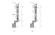
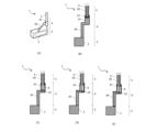
- the golf club 1 in Figures 19(A) to (E) is a modified example of the shape of the hosel 4.
- the hosel 4 is formed by combining a trapezoidal portion 4X that is trapezoidal (or substantially triangular) when viewed from the front and a crank-shaped portion 4Y that extends upward from the upper part of the trapezoidal portion 4X.
- the crank-shaped portion 4Y has two bent portions in the middle part in the extending direction.
- the head 3 is provided below the trapezoidal portion 4X
- the shaft 5 is provided above the crank-shaped portion 4Y.
- the golf club 1 shown in FIG. 19(C) differs from the golf club 1 shown in FIG. 19(B) in that it has a hosel cavity 8 in part of the crank-shaped portion 4Y. That is, the hosel cavity 8 is provided in part of the upper end side of the crank-shaped portion 4Y, and the rest of the crank-shaped portion 4Y except for the part where the hosel cavity 8 is provided is made of a solid material with a solid cross-section. In this case, the lower end of the vibration transmission member 20 is fixed to the inner surface of the hosel cavity 8 via a fixing device 22.
- the golf club 1 shown in FIG. 19(D) differs from the golf club 1 shown in FIG. 19(C) in that a hosel cavity 8 is provided over the entire length of the crank-shaped portion 4Y.
- the hosel cavity 8 is formed to connect the upper and lower ends of the crank-shaped portion 4Y.
- the lower end of the vibration transmission member 20 is fixed to the inner surface of the hosel cavity 8 via a fixing device 22.
- the golf club 1 shown in FIG. 19(E) differs from the golf club 1 shown in FIG. 19(D) in that a hosel cavity 8 is provided in both the trapezoidal portion 4X and the crank-shaped portion 4Y that form the hosel 4.
- the lower end of the vibration transmission member 20 is fixed to the inner peripheral surface of the hosel cavity 8 via a fixing device 22.
- the hosel cavity 8 is formed so as to communicate between the cavity in the trapezoidal portion 4X and the cavity in the crank-shaped portion 4Y, but the cavity in the trapezoidal portion 4X and the cavity in the crank-shaped portion 4Y may be separated and not communicate with each other.
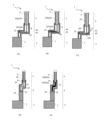
- the golf clubs 1 shown in Figures 20(A) to (E) are modified examples with respect to the configuration of the vibration transmission member 20.
- Each of the golf clubs 1 in Figures 20(A) to (C) has a crank-shaped hosel 4A similar to that in Figure 7(A), but the vibration transmission member 20 is different from that in Figure 7(A).
- the vibration transmission member 20 has one bending point 29 and is bent at one point.
- the first vibration transmission member 20X which is a portion of the vibration transmission member 20 that extends upward from the bending point 29, extends in the up-down direction.
- the second vibration transmission member 20Y which is a portion of the vibration transmission member 20 that extends rearward from the bending point 29, extends in the front-rear direction.
- the first vibration transmission member 20X and the second vibration transmission member 20Y are configured as rod members.
- the vibration transmission member 20 differs from that of FIG. 20(B) in that the second vibration transmission member 20Y extending rearward from the bending point 29 is composed of a long coil spring.
- the golf club 1 in Fig. 20(C) has an auxiliary vibration transmission member 20Z attached in the hosel cavity 8, and the vibration transmission member 20 is attached to this auxiliary vibration transmission member 20Z via a connection part 20K.
- the auxiliary vibration transmission member 20Z is disposed in the hosel cavity 8 in the crank-shaped hosel 4A in a posture extending in the front-rear direction, and both ends of the auxiliary vibration transmission member 20Z are fixed to the inner peripheral surface of the hosel cavity 8 via fasteners.
- One end (the lower end in the figure) of the vibration transmission member 20 is attached to the auxiliary vibration transmission member 20Z.
- the vibration transmission member 20 is indirectly fixed to the hosel 4 via the auxiliary vibration transmission member 20Z.
- the auxiliary vibration transmission member 20Z shown in Figure 20(C) may be attached to a hosel cavity 8 provided inside a flat hosel 4B (hosel 4) as shown in Figure 18(D). In this case as well, a good hitting feel can be provided to the user, and the hitting feel can be improved compared to existing golf clubs.
- the golf club 1 shown in Figures 20(D) and (E) has a hosel 4 that combines a trapezoidal portion 4X and a crank-shaped portion 4Y similar to that of Figure 19(D), and differs from Figure 19(D) in that a hosel cavity 8 is provided within the crank-shaped portion 4Y and across the upper portion (part) of the trapezoidal portion 4X.
- the vibration transmission member 20 has two bending points 29 and is bent in two places along the bending shape of the hosel cavity 8.
- the vibration transmission member 20 is composed of a rod member 20R and a coil spring 20C.
- the rod member 20R is disposed in the grip cavity (not shown) and the shaft cavity 9, and the coil spring 20C is disposed in the hosel cavity 8.
- the upper end of the coil spring 20C is connected to the lower end of the rod member 20R, and the lower end of the coil spring 20C is fixed to the upper part of the trapezoidal portion 4X.
- the coil spring 20C is disposed in the hosel cavity 8 in a shape that is bent in two places along the bent shape of the crank-shaped portion 4Y.
- ⁇ Weight material> 22A and 22B are perspective views for explaining modified examples of the head 3.
- the head 3 may have a built-in weight member 61 for changing the position of the center of gravity of the head 3.
- the center of gravity may be changed by making the mounting state (position and angle) of the weight member 61 adjustable.
- the mounting state of the weight member 61 may be manually adjustable by the user, or a weight motor 62 (drive source) for moving the weight member 61 may be provided.
- the golf club 1 provided with the weight member 61 has a head 3, a hosel 4, a shaft 5, and a grip, the grip 6 is integrally formed with the shaft 5, a vibration transmission member 20 is built in a shaft cavity 9 in the shaft 5 and a grip cavity 10 in the grip 6, the lower end of the vibration transmission member 20 is fixed to the hosel 4, and the grip cavity 10 has mounting members (grip inner plate 23 and grip inner fixing device 24) that connect the upper end of the vibration transmission member 20 to the grip 6 inside the grip cavity 10.
- Figure 22 (A) is a perspective view showing two sets of weight members 61 and a weight motor 62 built into the top surface of the head 3.
- the weight members 61 are made of a material with a different density than the material constituting the head 3, and are provided inside a hollow cylindrical recess formed in the top surface of the head 3.
- the weight motor 62 moves the weight members 61 in the rotational direction along the inner surface of the recess, thereby changing the position of each weight member 61. With this configuration, the position of the weight members 61 can be easily changed to move the center of gravity of the head 3, providing a good hitting feel.
- FIG. 22(B) is a perspective view showing weight members 61 provided inside a linear recess formed in the top surface of the head 3.
- the weight motor 62 changes the position of each weight member 61 by sliding the weight members 61 along the inner peripheral surface of the recess. Even with this configuration, the position of the weight members 61 can be easily changed to move the center of gravity of the head 3, providing a good hitting feel.
- Fig. 23 is a perspective view of the golf club 1 according to this modification.
- the basic configuration of the golf club 1 in Fig. 23 is the same as that of the golf club 1 shown in Fig. 1(B) above, and includes a head 3, a hosel 4, a shaft 5, and a grip.
- the grip 6 is formed integrally with the shaft 5.
- a vibration transmission member 20 is built into the shaft cavity 9 in the shaft 5 and the grip cavity 10 in the grip 6. The lower end of the vibration transmission member 20 is fixed to the hosel 4.
- the grip cavity 10 has an attachment member (grip inner plate 23 and grip inner fixing member 24) that connects the upper end of the vibration transmission member 20 to the grip 6.
- the golf club 1 may include a vibration sensor 95 built into the hosel 4 to detect vibrations transmitted from the hosel 4 to the vibration transmission member 20.
- the vibration sensor 95 may be attached to the outer surface of the hosel 4 or may be built into the hosel 4. If a hosel cavity 8 is formed inside the hosel 4, the vibration sensor 95 may be disposed inside the hosel 4.
- a vibration device 96 (actuator) that vibrates based on vibration information detected by the vibration sensor 95 may be built into the hosel 4. If a hosel cavity 8 is formed inside the hosel 4, the vibration device 96 may be disposed inside it.
- the vibration device 96 may function, for example, to directly amplify and output the vibration detected by the vibration sensor 95. By amplifying the vibration with the vibration device 96, it is possible to increase the vibration that is actually transmitted to the user, further improving the feel of the hit.
- a speaker 96A that emits sound based on information on vibrations detected by the vibration sensor 95 may be built into the hosel 4. If a hosel cavity 8 is formed inside the hosel 4, a speaker 96A including an amplifier may be placed inside it. The speaker 96A may function to amplify and output the vibrations detected by the vibration sensor 95 as sound, for example. In this way, when a golf ball is hit with one of the striking surfaces of the golf club, the vibrations at that time are detected by the vibration sensor 95 and can be heard as sound from the speaker 96A. At this time, the hollow hosel 4, shaft 5, and grip 6 function as a speaker box, amplifying and outputting the sound related to the vibrations. As a result, the golf club 1 can function as a kind of electronic musical instrument.
- another vibration device 97 (actuator) and speaker 97A may be built into the grip 6.
- the vibration device 97 and speaker 97A are disposed, for example, inside the grip cavity 10 in the grip 6.
- the vibration device 97 and speaker 97A function to directly amplify and output the vibrations detected by the vibration sensor 95, or to directly amplify and output the vibrations detected by the vibration sensor 95 as sound.
- the vibrations and sounds that are actually transmitted to the user can be made even larger, further improving the hitting feel.
- the golf club 1 may further include a transmitter 101 for transmitting information detected by the vibration sensor 95 to an outside.
- the transmitter 101 is built into, for example, the hosel 4. When a hosel cavity 8 is formed inside the hosel 4, the transmitter 101 may be disposed inside the hosel 4.
- the information detected by the vibration sensor 95 may be transmitted to an external device such as a computer (not shown) via the transmitter 101, for example, by wireless connection or wired connection.
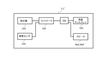
- the golf club 1 may include a controller 100 having a rhythm box function and a synthetic voice generating function for informing the player of the rhythm when the golf ball is hit.
- the controller 100 is built into the hosel 4, for example. If a hosel cavity 8 is formed inside the hosel 4, the controller 100 may be disposed inside the hosel.
- a speaker 96A is connected to the output side of the controller 100. When the golf ball is hit, one of the rhythm sound and the synthetic voice generated by the controller 100 can be output from the speaker 96A by either the rhythm box function or the synthetic voice generating function of the controller 100. Note that the on/off of the rhythm box function and the synthetic voice generating function of the controller 100, volume adjustment, and other various operations can be input from an indicator (not shown).
- the indicator may be built into the golf club 1.
- the indicator may be configured by an external device (e.g., a smartphone) connected by wireless connection.
- the various functions of the controller 100 may be configured by an external device (e.g., a smartphone) connected by wireless connection.
- the golf club 1 shown in Fig. 24 is a modified example of the golf club 1 shown in Fig. 23.
- the vibration sensor 95, the vibration device 96, the speaker 96A, the transmitter 101, and the controller 100 built into the hosel 4 of the golf club 1 shown in Fig. 23 may be built into the shaft 5.
- 24 shows an example of a configuration in which a vibration sensor 95', a vibration device 96', and a speaker 96A' are further built into the shaft 5 of the golf club 1 shown in FIG. Without being limited to this, all of the vibration sensor, vibration device, speaker, transmitter, and controller may be built into the shaft 5.
- the vibration sensor, vibration device, speaker, transmitter, and controller may be built into only one of the hosel 4 and the shaft 5, or may be built into both. Also, some of the vibration sensor, vibration device, speaker, transmitter, and controller may be built into one of the hosel 4 and the shaft 5, and the rest may be built into the other of the hosel 4 and the shaft 5 (distributed or combined).
- a liquid crystal display 102 (display device, electric display member) may be added (display function).
- the liquid crystal display 102 is arranged, for example, on the surface facing the upper side of the head 3, and is connected to the output side of the controller 100.
- the liquid crystal display 102 can display the vibration data detected by the vibration sensors 95, 95' as numerical values, graphs, etc.
- the liquid crystal display 102 may also display the launch direction of the golf ball.
- the controller 100 controls the indicator (see reference numeral 103 in FIG. 33) to transmit an instruction signal for displaying the launch direction of the golf ball to the liquid crystal display 102 to cause the liquid crystal display 102 to display the launch direction of the golf ball.
- the indicator 103 (FIG. 33) is an input means for inputting an instruction for the launch direction of the golf ball.
- the display on the liquid crystal display 102 may be an arrow indicating the direction in which the golf ball will be launched, or a series of multiple circles. In this case, the circles may be made smaller as they approach the tip indicating the direction. This configuration not only improves the hitting feel, but also allows the liquid crystal display 102 to freely display the direction in which the golf ball will be launched, improving convenience.
- the indicator 103 and the controller 100 can be replaced by a smartphone. In this case, it is preferable to use a wireless line for connecting the controller 100 and the liquid crystal display 102.
- the instructions input to the indicator 103 may be input by, for example, a user of the golf club 1, an instructor (trainer), or an assistant (caddie).
- the mounting positions of the vibration sensor 95, vibration device 96, speaker 96A, transmitter 101, controller 100, vibration sensor 95', vibration device 96', speaker 96A', LCD display 102, vibration device 97, and speaker 97A are not limited to the illustrated example, and may be any position on the golf club 1.
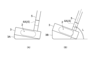
- ⁇ Adapter> 25(A) and (B) are side views for explaining yet another modified example of the above-mentioned golf club 1.
- a golf club 1 having a crank-shaped hosel 4A (hosel A) as shown in Fig. 1(A) is given as an example, but the shape of the hosel 4 is not limited thereto.
- One of a plurality of adapters 3A, 3B is detachably attached to the underside of the head 3 of the golf club 1.
- a plurality of types of these adapters 3A, 3B are prepared, which differ, for example, in shape, mass, center of gravity, etc.
- the adapter 3A shown in Fig. 25(B) is used when it is desired to increase the lie angle L more than the adapter 3B shown in Fig. 25(A).
- the adapters 3A and 3B are preferably attached to the underside of the head 3 via an easily detachable locking structure (clip) or fastening structure (screw).
- clip easily detachable locking structure
- screw fastening structure
- the golf club 1 of this invention comprises a head 3, a shaft 5, a hosel 4, and a grip 6.
- the head 3 has a striking surface 2 for striking a golf ball.
- the shaft 5 is formed in an axial shape.
- the grip 6 is provided at the other end of the shaft 5 and is held by a user.
- the shaft 5 has a hollow shaft cavity 9 (first cavity) therein, the grip 6 has a hollow grip cavity 10 (second cavity) therein communicating with the shaft cavity 9 (first cavity), and a vibration transmission member 20 is built into the shaft cavity 9 (first cavity) and the grip cavity 10 (second cavity).
- the vibration transmission member 20 is formed in an elongated shape, one end of which is fixed to the hosel 4, and the other end of which is fixed to a grip inner plate 23 and a grip inner fixing device 24 (mounting member) provided inside the grip cavity 10 (second cavity).
- the vibration transmission member 20 transmits vibrations generated on the striking surface 2 to the grip 6.
- the vibrations generated on the striking surface 2 of the head 3 can be efficiently transmitted to the grip 6 without attenuation, improving the feel on impact.
- the shaft cavity 9 and the grip cavity 10 can reverberate the vibrations, making the sound heard by the user louder. This further improves the feel and sound on impact.
- the hosel 4 of the present invention is configured of a solid material having a rectangular flat plate shape and a solid cross section, as shown in Fig. 1(B), for example, by extending a planar flat hosel 4B (hosel 4) of a certain thickness parallel to the striking surface 2, the vibration of the striking surface 2 is converted into a planar vibration (membrane vibration) of the hosel 4. This allows the vibration to be efficiently transmitted to the vibration transmitting member 20, allowing the user to feel the vibration accurately and delicately.
- the hosel 4 of the present invention is made of a solid material having two bent portions in the middle and a solid cross section, as shown in Fig.
- the vibrations of the striking surface 2 are transmitted to the vibration transmission member 20 via the crank-shaped hosel 4A (hosel 4). Therefore, the crank shape improves the vibration transmission efficiency, while the vibrations generated on the striking surface 2 of the head 3 can be efficiently transmitted to the grip 6 without attenuation, improving the feel on impact.
- the hosel 4 of the present invention may have a hosel cavity 8 (third cavity) formed therein, which is hollow.
- a hosel cavity 8 third cavity formed therein, which is hollow.
- sound can be generated in the hosel cavity 8. This allows the user to confirm the vibration of the striking surface 2 as sound, further improving the feel on impact.
- the hosel 4 may be in a crank shape having two bent portions in the middle, or in a rectangular flat plate shape.
- the attachment member (rack 41, pinion 42, motor 43, and winding device 44 in the figure) that connects the other end of the vibration transmission member 20 to the grip 6 may be provided so that its position can be adjusted in the extension direction of the grip 6.
- the position to which the vibration of the vibration transmission member 20 is transmitted can be adjusted, and the vibration can be transmitted to the grip 6 efficiently. Therefore, the hitting feel can be further improved.
- the hosel 4 has a built-in vibration sensor 95 that detects vibrations generated on the striking surface 2, which makes it possible to electrically process the vibrations in addition to transmitting them via the vibration transmission member 20.
- the vibrations detected by the vibration sensor 95 can be amplified and output as sound, allowing the user to confirm the vibrations on the striking surface 2 as sound, further improving the feel of the hit.
- the hosel 4 has a built-in vibration device 96 that vibrates based on information detected by a vibration sensor or a speaker 96A that emits sound. This makes it possible to increase the vibration and sound that are actually transmitted to the user, thereby further improving the feel of the hit.
- the vibration and sound can be increased at the user's hand, further improving the hitting feel.
- a mass member 26 that acts as a weight for amplifying vibration may be attached to the vibration transmission member 20, 20' of the present invention.
- the vibration of the vibration transmission member 20 can be easily amplified, or the damping of the vibration can be suppressed, thereby improving the vibration transmission efficiency. Therefore, the hitting feeling can be further improved.
- the hosel 4 of the present invention has a hosel cavity 8 (third cavity) formed therein, for example as shown in Fig.
- an auxiliary vibration transmission member 20Z that transmits vibrations generated on the striking surface 2 to the vibration transmission member 20 may be provided inside the hosel cavity 8 (third cavity) to transmit vibrations generated on the striking surface 2 to the vibration transmission member 20.
- the auxiliary vibration transmission member 20Z allows the vibrations generated on the striking surface 2 to be efficiently transmitted to the vibration transmission member 20 without attenuation, thereby further improving the feel on impact.
- the head 3 of the present invention may have a head cavity 7 (fourth cavity) inside.
- the head cavity 7 can also resonate vibrations, and the sound heard by the user can be amplified. This can further improve the hitting feel.
- a weight member 61 for changing the position of the center of gravity of the head 3 can be applied to the head 3 of the present invention. By changing the attachment position and attachment angle of such a weight member 61, the center of gravity of the head 3 can be easily moved, and a good hitting feel can be provided.
- a weight motor 62 may be provided as a drive source for moving the weight member 61.
- the weight member 61 is provided, for example, inside a hollow cylindrical recess formed in the top surface of the head 3.
- the weight motor 62 also drives and rotates the weight member 61 along the inner peripheral surface of the recess. With this configuration, the center of gravity of the head 3 can be easily adjusted using the weight motor 62. This can further improve the feel of the hit.
- the golf club 1 of the present invention can be equipped with a controller 100 having a rhythm box function and a synthetic voice generating function that notifies the user of the rhythm when hitting the golf ball, as shown in Figures 23 and 24.
- a controller 100 having a rhythm box function and a synthetic voice generating function that notifies the user of the rhythm when hitting the golf ball, as shown in Figures 23 and 24.
- one of the rhythmic sound and the synthetic voice generated by the controller 100 can be output from the speaker 96A, providing assistance in hitting the golf ball to the user of the golf club 1.
- the golf club 1 of this case has one of a number of adapters 3A, 3B removably attached to the underside of the head 3.
- the adapter 3A, 3B suited to the physique and hitting form of the user of the golf club 1, it becomes easier to optimize the swing trajectory of the golf club 1, and it becomes possible to improve the effect of practice.
- the golf club 1 of this embodiment may have a transmitter that transmits signals from the vibration sensor 95 to the outside. This allows information about the vibrations detected by the vibration sensor 95 (vibration data, vibration information) to be used by an external device (such as a smartphone, computer, or data server).
- an external device such as a smartphone, computer, or data server.
- the hosel hollow portion 8 may have openings 80, 80A, 80B that communicate the inside of the hosel hollow portion 8 with the outside.
- the openings 80, 80A, 80B allow the reverberation in the hosel hollow portion 8 to be transmitted to the outside of the hosel 4, so that the sound heard by the user can be amplified, the hitting feel can be further improved, and the hitting sound can be sufficiently confirmed.
- the openings 80, 80A, 80B can be closed with lids 81, 81A, 81B.
- the golf club 1 of this invention may further have openings 90, 92 that connect the internal space of the shaft cavity 9 (first cavity) or the internal space of the grip cavity 10 (second cavity) to the outside, and lids 91, 93 that close the openings 90, 92.
- the openings 90, 92 and the lids 91, 93 form a covered inspection window for the vibration transmission member 20 in the shaft 5 or the grip 6. This allows the condition of the vibration transmission member 20 in the shaft 5 or the grip 6 to be easily inspected.
- the multiple vibration transmission members 20, 20' may be collectively attached to a single mounting member, or each of the multiple vibration transmission members 20, 20' may be individually attached to a corresponding mounting member.
- a plurality of sets of racks 41, pinions 42, motors 43, and winding devices 44 may be provided as a plurality of mounting members corresponding to the plurality of vibration transmission members 20, 20', respectively.
- the positions of the plurality of vibration transmission members 20, 20' can be individually adjusted in the extending direction of the grip 6, and vibrations can be efficiently transmitted to the grip 6. Therefore, the hitting feel can be further improved.
- the other ends of the multiple vibration transmission members 20, 20' are fixed to an upper mounting member 27U (mounting member, grip side plate) provided inside the grip cavity 10 (second cavity), and one end is fixed to a lower mounting member 27D (mounting member, hosel side plate).
- Each of the upper mounting member 27U and the lower mounting member 27D is in the shape of a disk extending along a plane intersecting the extending direction of the vibration transmission members 20, 20', and is provided with multiple connecting holes 28U, 28D that connect the multiple vibration transmission members 20, 20', respectively.
- the multiple vibration transmission members 20, 20' can be attached with a simple configuration.
- vibration transmission members 20 can be applied to any of the golf clubs described above.
- Various shapes of vibration transmission members 20 and various components such as upper mounting member 27U and lower mounting member 27D, fixture 22, grip internal fixture 24, winding device 44, etc. can be freely combined.
- the battery for the smartphone also serves as the battery for the above circuit.
- the golf club 1 can be manufactured using a variety of techniques in addition to or in place of the usual golf club manufacturing techniques.
- the part can be manufactured using a 3D printer, a seamless welding method, a casting method, or an appropriate combination of these methods.
- the practice machine T is provided with a cup area T1 in which a cup C is provided on the golf ball rolling surface, and a hitting area T2 which is provided apart from the cup C, has a golf ball rolling surface, and is a hitting position for a user.
- the practice machine T is, for example, a practice green, and in this case, the cup C is recessed into the golf ball rolling surface of the cup area T1.
- the practice machine T is a golf practice mat.
- the cup C is not recessed, but is provided as a predetermined area (flat surface) on the golf ball rolling surface.
- the cup C may be formed as a shallow recessed portion on the mat.
- the cup C is not limited to a hole, and may be any target position for cupping in a golf ball.
- the training machine T is a facility for a user (golfer) standing in a hitting area T2 to practice putting by hitting a ball B toward a cup C provided in a cup area T1 with a golf club 1'.
- the golf ball rolling surface is the surface on which the hit ball B rolls, and is the floor surface of the cup area T1 and the hitting area T2.
- the directions used to explain the golf practice system S are defined as follows. Using the user putting in the hitting area T2 as a reference, the direction from the user toward the cup C is “front” (marked “F” in the figure), and the opposite side of "front” is “back” (marked “B” in the figure), with “left” and “right” (marked “L” and “R” in the figure) defined based on “front.” In addition, “up” and “down” (marked “U” and “D” in the figure) are defined based on the direction in which gravity acts.
- the cup C provided in the cup area T1 of the training machine T is positioned forward of the hitting area T2.
- a pin P made of a rod-shaped member is erected on the cup C.
- the pin P functions as a marker for the cup C to the user in the hitting area T2.
- the system S also includes a control unit 300 that manages the system S, and a terminal device 400 owned by the user.
- the devices 200 to 700 in the system S are connected to each other via a wireless communication network so that they can send and receive data, and can work in conjunction with each other.
- the wireless communication network is a network that complies with well-known wireless communication standards such as Wi-Fi and Bluetooth (registered trademark).
- the outline of this system S is that the control unit 300 generates guide information for providing guidance to the user's golf play based on monitor information acquired by the units 200, 500, 600 and 700, the control unit 300 transmits the guide information to the terminal device 400 etc., and the terminal device 400 etc. provides guidance based on the guide information in advance (in advance) before the user hits the ball, for example.
- the devices 200 to 700 work together via a network to provide interactive guidance for the user's golf practice.
- the guide is advice to the user regarding golf play, model plays, etc. Specifically, examples of advice and model plays include hitting form, swing rhythm of the golf club, ball launch direction, timing, etc.
- the monitor information acquired by the units 200, 500, 600, and 700 in the present system S is a measurement result related to the user's golf play.
- the monitor information includes a plurality of video data, cup-in information, ball hitting information, golf club head angle, and the like.
- the cup unit 200 , the pin unit 500 , the club unit 700 and the photographing unit 600 are monitor information sources that provide monitor information to the control unit 300 .
- the cup unit 200 is built into (attached to) the cup C, and is a mechanism provided for providing monitor information in the cup C to the control unit 300 .
- the cup unit 200 includes a first control device (referred to as the "control device” in the figure) 201, a first sensor (first detection means, referred to as the “sensor” in the figure) 202, and a first communication device (first transmitting device, referred to as the "communication device” in the figure) 203.
- the first control device 201 is an electrical control device including a processor that controls the cup unit 200, a storage device, and the like.
- a first sensor 202 and a first communication device 203 are connected to the first control device 201 so as to be capable of transmitting and receiving data.
- the first sensor 202 is a detection means provided for detecting cup-in information indicating that the golf ball B has been cupped into the cup C.
- the first sensor 202 may be, for example, an impact sensor that detects the impact of a golf ball B falling into a cup C.
- the cup unit 200 includes additional devices such as a camera 205 for photographing the surroundings of the cup C, an audio device 206 including an amplifier, a speaker, and a microphone, a lighting device 207, a laser irradiator 208, and a power source (not shown) for supplying power.
- a camera 205 for photographing the surroundings of the cup C
- an audio device 206 including an amplifier, a speaker, and a microphone
- a lighting device 207 including an amplifier, a speaker, and a microphone
- a lighting device 207 including an amplifier, a speaker, and a microphone
- a lighting device 207 including an amplifier, a speaker, and a microphone
- a lighting device 207 including an amplifier, a speaker, and a microphone
- a lighting device 207 including an amplifier, a speaker, and a microphone
- a lighting device 207 including an amplifier, a speaker, and a microphone
- a lighting device 207 including an amplifier, a speaker, and a microphone
- the pin unit 500 is attached to the pin P, and is a mechanism provided to provide monitor information about the periphery of the pin P to the control unit 300.
- the pin unit 500 includes a second control device (referred to as a "control device” in the figure) 501, a first camera (first photographing means, referred to as a “camera” in the figure) 502, a second communication device (second transmitting device, referred to as a “communication device” in the figure) 503, a first illuminator (referred to as a "laser” in the figure) 504, and a second photoreceiver (referred to as a "photoreceiver” in the figure) 505.
- the second control device 501 is an electrical control device including a processor for controlling the pin unit 500, a storage device, and the like.
- a first camera 502, a second communication device 503, a first illuminator 504, and a second light receiver 505 are connected to the second control device 501 so as to be capable of transmitting and receiving data.
- the first camera 502 is an image sensor provided to capture an image (first image data) of the area around the pin P.
- the first camera 502 is an imaging means that captures an image at least from the pin P toward the hitting area T2.
- the first camera 502 may be configured as a "360-degree camera" that can capture images in all directions, 360° in the vertical and horizontal directions, centered on the pin P.
- the first camera 502 is not limited to a 360-degree camera, and may be a camera that captures an area narrower than 360 degrees.
- the first camera 502 may also be configured as a 3D camera.
- the second communication device 503 is a wireless communication device connected to the control unit 300 (external) via a wireless communication network. Through the second communication device 503, the image data captured by the first camera 502 can be transmitted to the control unit 300 (external) and information can be received from the external.
- the first irradiator 504 is a light source that irradiates a guide laser light that shows a straight line from the pin P toward the hitting area T2. The straight line indicates the rolling trajectory of the ball B.
- the trajectory of the laser light functions as a guide line that indicates the trajectory of the ball B.
- the trajectory of the ball B is the trajectory that connects the cup C to a predetermined hitting position.
- the second light receiver 505 is a light receiving element (sensing device) for receiving (detecting) the guide laser light (guide sub-laser light) from a second irradiator 705 provided in the club unit 700 described later.
- a speed sensor for example, a speed sensor, an acceleration sensor, a gyro sensor, a magnetic sensor, a biometric authentication sensor, an air pressure sensor (pressure sensor), a temperature sensor, a microphone (sound pressure sensor), a direction sensor, a proximity sensor, a brightness sensor (ambient light sensor), a human sensor, an anemometer, a wind vane, an infrared sensor, an infrared camera, a snow accumulation meter (such as a snow accumulation meter based on laser reflection or an image captured by a camera), etc.
- a speed sensor for example, a speed sensor, an acceleration sensor, a gyro sensor, a magnetic sensor, a biometric authentication sensor, an air pressure sensor (pressure sensor), a temperature sensor, a microphone (sound pressure sensor), a direction sensor, a proximity sensor, a brightness sensor (ambient light sensor), a human sensor, an anemometer, a wind vane, an infrared sensor, an infrared camera, a snow
- the light-emitting function (lighting device 507) attached to the pin unit 500 can be used to enhance the identification of the pin P (i.e., the pin P is provided with a lighthouse function).
- the lighting by the lighting device 507 attached to the pin P provides, for example, illumination, neon, lights, spotlights, rotating spotlights, mirror balls, LED lighting, etc., around the pin P.
- the lighting device 507 attached to the pin P turns on when, for example, a human sensor included in the sensor 508 of the pin unit 500 detects a person approaching the pin P. Such a lighting function can be switched on and off.
- the third control device 701 is an electrical control device including a processor for controlling the club unit 700, a storage device, and the like. Each of the elements 702 to 710 is connected to a third control device 701 so as to be able to transmit and receive data.
- the second camera 702 is an image sensor provided to capture an image (second image data) of the surroundings of the golf club 1'. In this embodiment, the second camera 702 is an image capture means for capturing an image at least from the head of the club 1' toward the front.
- the second sensor 704 is a detection means for detecting impact information related to the impact of the golf ball as one of the monitor information.
- the second sensor 704 is, for example, an impact sensor for detecting impact data when the golf ball is hit with the striking surface, and an angle sensor for detecting the angle of the head when hitting the golf ball, and is built into the head 3 (FIG. 1(A) etc.).
- the vibration sensor 710 is a detection means for detecting vibration information related to the vibration of the vibration transmission members 20, 20' (FIG. 5(A) etc.) provided on the golf club 1' as one of the monitor information.
- the vibration sensor 710 is built into the hosel 4, for example (see reference numeral 95 in FIG. 23).
- the vibration sensor 710 may be built into the shaft 5 or the grip 6.
- the second irradiator 705 is a light source that irradiates a guide laser beam forward from the head of the golf club 1'.
- the trajectory of the laser beam functions as a guide line that indicates the trajectory of the ball B.
- the trajectory of the ball B is a trajectory that is substantially perpendicular to the striking surface of the head and extends linearly forward from the striking surface.
- the display device 706 is a display device that displays visual information.
- An example of the display device 706 is an LCD.
- the audio device 707 is an audio input/output device that includes an amplifier, a speaker, and a microphone and reproduces audio signals and inputs voice.
- the first light receiver 708 is a light receiving element (sensing device) for receiving (detecting) the guide laser light from the first irradiator 504 provided in the pin unit 500 .
- the third communication device 703 is a wireless communication device connected to the control unit 300 (external) via a wireless communication network. Via the third communication device 703, it is possible to transmit video data captured by the second camera 702 and detection signals from the second sensor 704 to the control unit 300 (external) and to receive information from the external.
- the club unit 700 is provided with a lighting device 709, a power source for supplying electric power (not shown), and an automatic operation mechanism for automatically operating various adjustments related to shooting by the second camera 702 (for example, focusing, brightness adjustment, tracking of a subject to be shot, switching of shooting direction, etc.), which are detachable from the club unit 700 or integral with the club unit 700.
- sensors for example, a speed sensor, an acceleration sensor, a gyro sensor, a magnetic sensor, a biometric authentication sensor, an air pressure sensor (pressure sensor), a temperature sensor, a microphone (sound pressure sensor), a direction sensor, a proximity sensor, a brightness sensor (ambient light sensor), a human sensor, an anemometer, a wind vane, an infrared sensor, an infrared camera, a snow accumulation meter (such as a snow accumulation meter based on laser reflection or an image captured by a camera), etc.
- a speed sensor for example, a speed sensor, an acceleration sensor, a gyro sensor, a magnetic sensor, a biometric authentication sensor, an air pressure sensor (pressure sensor), a temperature sensor, a microphone (sound pressure sensor), a direction sensor, a proximity sensor, a brightness sensor (ambient light sensor), a human sensor, an anemometer, a wind vane, an infrared sensor, an infrared camera, a snow accumulation meter
- the golf club 1' can be configured as an "AI club” having multiple functions, such as automatically taking pictures of the surroundings, detecting hitting information, emitting laser light, outputting sound, operating by voice command input, and emitting light.
- the lighting by the lighting device 709 attached to the golf club 1' provides, for example, lighting, illumination, neon, lights, spotlights, rotating spotlights, mirror balls, LED lighting, etc., around the golf club 1'.
- the lighting device 709 attached to the golf club 1' turns on, for example, when a human sensor mounted on the golf club 1' detects a person approaching the golf club 1'. Such a lighting function can be switched on and off.
- the photographing unit 600 is attached to the hitting area T2 of the golf training machine, and is a mechanism provided to photograph images of the user standing in the hitting area T2 and the user's surroundings, and provide the image data as monitor information to the control unit 300 and equipment within the system S, including the terminal device 400.
- 26 includes a plurality of cameras 602.
- the plurality of cameras 602 includes a left camera 602L (one of the third imaging means) and a right camera 602R (one of the third imaging means) provided on both the left and right sides of the striking area T2, a rear camera 602B (one of the third imaging means) provided behind the striking area T2, and a head-mounted head camera 602H (fourth imaging means) worn on the user's head.
- the control unit 300 is a computer that controls the system S.
- the control unit 300 is installed at an arbitrary location, such as near the training aircraft T or at a system base remote from the training aircraft T.
- the control unit 300 includes a control device 301, a receiving device (first receiving device, referred to as “receiving device” in the figure) 302, a first transmitting device (fourth transmitting device, referred to as “transmitting device” in the figure) 303, and a storage device 304.
- the receiving device 302 and the transmitting device 303 are devices for transmitting and receiving data to and from the outside via a wireless communication network.
- the control unit 300 receives, via the receiving device 302, various types of video data and sensor detection data acquired by the units 200, 500, 600, and 700 in the system S as monitor information.
- the control device 301 is a device that generates predetermined guide information based on the above-mentioned monitor information, and is, for example, a processor that implements a software program for generating guide information.
- the guide information is information for providing the user with guidance on the above-mentioned golf play.
- the transmitting device 303 transmits the guide information generated by the control device 301 to the terminal device 400 .
- the transmitting device 303 may transmit guide information to at least one of the cup unit 200, the pin unit 500, the club unit 700 and the photographing unit 600 (i.e., any device within the system S) in addition to or instead of the terminal device 400.
- the various functions of the control unit 300, including the guide information generation process in the control device 301, may be provided by cloud computing using computing services on a cloud environment (Internet environment).
- the display 402 is an example of a display device that displays (presents) a guide based on the guide information to the user using some kind of visual image, such as a moving image or a still image.
- An example of the display 402 is an LCD.
- the input device 404 is, for example, a touch panel sensor or a button switch.
- Examples of presentation devices other than the display device 402 include an audio device 405 that outputs sound, a light-emitting lighting device (not shown), and a vibration generating mechanism (not shown) that generates vibrations.
- an audio device is used as the guide presenter
- the guide for golf play is presented by, for example, music, voice, electronic sound, sound effect, or some other sound.
- a lighting device is used as the guide presenter
- the guide display or support content is presented by blinking light or changing the light color.
- the guide for golf play is presented by vibration.
- the terminal device 400 may have various built-in sensors.
- sensors include a gyro sensor, a magnetic sensor, a GPS, a biometric authentication sensor, a radar sensor, an air pressure sensor (pressure sensor), a temperature and humidity sensor, a microphone (sound pressure sensor), a direction sensor, a proximity sensor, a brightness sensor (ambient light sensor), an image sensor (camera 406), a vital sensor, a pulse sensor, a body temperature sensor, a moisture sensor, a blood pressure sensor, a distance sensor, a tilt sensor, a topographical sensor, a human presence sensor, an anemometer, a wind vane, an infrared sensor, an infrared camera, a snow depth gauge (such as a snow depth gauge based on laser reflection or an image captured by a camera), etc.
- sensors include a gyro sensor, a magnetic sensor, a GPS, a biometric authentication sensor, a radar sensor, an air pressure sensor (pressure sensor), a temperature and humidity sensor, a
- control device 301 constantly receives, as monitor information, video data acquired from the camera 205 of the cup unit 200, the first camera 502 of the pin unit 500, the cameras 602L, 602R, 602B, 602H of the photographing unit 600, and the second camera 702 of the club unit 700, cup-in information from the first sensor 202 of the cup unit 200, impact information from the impact sensor included in the second sensor 704 of the club unit 700, angle data from the angle sensor, and vibration information from the vibration sensor 710 of the club unit 700.
- the control device 301 stores the received video data, cup-in information, impact information, angle data, and vibration information (monitor information) in a storage device and accumulates them as big data, and generates guide information based on this monitor information to provide guidance to the user on their golf play.
- the control device 301 analyzes the acquired video data using a known image analysis technique to calculate play situation estimation data.
- the play situation estimation data is data estimated from the video of the current play situation.
- the estimated data includes, for example, the user's current position, the user's posture before the swing, head-up analysis, head-up check, the user's line of sight, head position, stance, distance to the pin P, and the like.
- the play situation estimation data allows the control unit 300 to grasp (estimate) the play situation based on the monitor information.
- the control device 301 generates guide information based on the calculated play situation estimation data and the sample (model play) data.
- the guide information is advice (guide) for achieving a better hit based on the current play situation (the user's current position, the user's posture before swinging, head-up analysis, head-up check, the user's line of sight, head position, stance, distance to the pin P, etc.).
- tips for playing golf such as a sample swing trajectory, a sample form, swing rhythm, ball launch direction, standing position, foot width, accurate impact, etc., are presented in the form of pictures, photographs, videos, sounds, rhythmic sounds, characters, etc.
- the playing form of a master or expert such as a professional golf player, can be presented as an example play.
- the storage device 304 is assumed to have stored in advance model data that serves as a reference for guiding golf play, as well as various video, image, and audio data for generating guide information.
- Model data includes, for example, models of the user's posture before a swing, the user's line of sight, head position, stance, body movement, and golf club trajectory.
- the guide content is at least one of a guide video and a guide audio.
- the guide video may include the user's eye position during the swing, head position, posture, head-up analysis, head-up check, hitting form, golf club stroke trajectory, head angle, ball launch angle, head speed, strike strength, swing tempo, glove path (trajectory), and putter face direction (angle).
- the guide voice may be a metronome sound (including music, voice, and other rhythmic sounds) that guides the swing rhythm of the golf club, advice (voice comments) for improving golf play, etc.
- the device may be connected to an interactive online golf lesson service via the Internet.
- a predicted outcome from the current playing situation may be presented.
- Examples of predicted outcomes from the current playing situation include a predicted ball trajectory, a predicted swing trajectory, a predicted form, etc.
- the control device 301 can take into account monitor information accumulated as big data, driving range information regarding the gradient of the green G, grass grain, etc., and personal information regarding the user's age, sex, physique, constitution, height, weight, golfing skills, etc. Taking into account various information can improve the accuracy of the golf play guide provided by the guide information. Also, by adding the user's golf play information history to the guide information, the user's "habits" can be more easily reflected, making it possible to provide personalized golf play guides.
- the control device 301 may also have a function (generation AI) that learns from various collected and accumulated data and automatically generates guide information.
- generation AI generation AI
- a laser beam (guide laser beam) is irradiated from the first illuminator 504 of the pin unit 500 toward the hitting area T2.
- a first light receiver 708 is provided in the club unit 700 of the golf club 1' used by the user of the hitting area T2. Therefore, when the user stands at an appropriate position with respect to the pin unit 500, the first light receiver 708 of the club unit 700 receives the laser beam from the first illuminator 504.
- the display in the system S displays the same. Examples of the display include the display 402 of the terminal device 400 and the display device 706 of the club unit 700.
- the display may be audibly output from a speaker in the system S.
- the speakers in the system S include an audio device 405 in the terminal device 400, an audio device 206 in the cup C, an audio device 506 in the pin P, an audio device 707 in the club unit 700, and the like.
- a laser light (guide sub-laser light) is emitted from the second illuminator 705 of the club unit 700.
- the laser light from the second illuminator 705 is emitted toward the pin P (pin unit 500).
- the pin unit 500 is provided with a second receiver 505. Therefore, when the user stands in an appropriate position relative to the pin unit 500, the second receiver 505 of the pin unit 500 receives the laser light from the second illuminator 705 of the club unit 700.
- the display in the system S displays this fact.
- Examples of the display include the display 402 of the terminal device 400 and the display device 706 of the club unit 700.
- the second receiver 505 receives the guide sub-laser light
- a notification to that effect may be given by audio output from a speaker in the system S.
- Speakers in the system S include the audio device 405 of the terminal device 400, the audio device 206 of the cup C, the audio device 506 of the pin P, and the audio device 707 of the club unit 700.
- the display in the system S displays that fact
- the display in the system S displays that fact
- the display in the system S displays that fact, so that the user can confirm by the display that he or she is standing in an appropriate position with respect to the pin unit 500.
- the content of the display may be anything as long as it notifies the user that he or she is standing in an appropriate position with respect to the pin unit 500.
- the trajectories of the laser light from the first light receiver 708 and the laser light from the second light receiver 505 function as guide lines showing the trajectory of the ball B, so that the user can understand the direction in which the ball B is to be hit while standing at an appropriate position relative to the pin unit 500.
- a visual guide regarding putting (hitting the ball B) can be provided to the user.
- the bidirectional guide light can provide more reliable guidance.
- the irradiation angle between the first illuminator 504 of the pin unit 500 and the second illuminator 705 of the club unit 700 can be automatically adjusted based on the results of analysis of the above monitor information and video data. This allows for accurate guidance that reflects the current playing situation by adjusting the direction of the laser light.
- control device 301 can provide feedback on the play result after the hit is completed based on the results of analyzing the video data.
- the control device 301 identifies the swing made by the user in the video based on the result of analyzing the video data, analyzes the identified swing, and tracks the hit golf ball B in the video to analyze the movement of the golf ball B.
- analyzing and evaluating the swing includes analyzing the user's form and analyzing the movement of the golf club (head).
- analysis items for the user's form include the user's eye position, head position, posture, head-up analysis, and head-up check.
- analysis items for golf club (head) movement include the golf club stroke trajectory, head angle, head speed, impact strength, putter face angle, ball launch angle, club path (in-out/out-in movement of the club head at impact), swing tempo, swing flow, and club head flow.
- Examples of analysis items for the movement of the golf ball B include the speed of the golf ball B, the launch angle (launch direction) of the golf ball B, and the flight distance of the golf ball B.
- the control device 301 calculates analysis result data for each of the above items by analyzing the video data, and generates the calculated various analysis result data as practice support information.
- the analysis result data generated as support information is used as information for displaying the analysis results and evaluation of the golf play for each of the above items.
- the control device 301 transmits the analysis result data generated as support information to the terminal device 400.
- the fourth control device 401 of the terminal device 400 displays the analysis results and evaluation of the golf play for each of the above items on the display 402 as practice support content based on the received analysis result data (support information). In other words, feedback on the golf play results is provided. Such feedback contributes to improving the user's golfing technique. Furthermore, visualizing one's own play as numerical values and images also contributes to improving the enjoyment of golf.
- Examples of analysis results of golf play displayed as support content on the display 402 are listed below. That is, examples of support content include the speed of golf ball B, launch angle (launch direction) of golf ball B, flight distance of golf ball B, number of rotations of ball B, rotation direction of ball B, rotation speed, ball quality, quality of rotation, video recording the user's form during a swing, continuous photos recording the user's form during a swing using high-speed photography, the user's line of sight during a swing, head position, posture, head-up analysis, head-up check, golf club stroke trajectory, measured head angle, measured head speed, measured impact strength, swing tempo, swing flow, and club head flow.
- the golf club stroke trajectory includes the so-called grab pass.
- the head angle includes the direction (angle) of the putter face.
- the feedback on the golf play result is not limited to the above-mentioned visual feedback, but may be provided by audio information (i.e., auditory feedback).
- the auditory feedback is to transmit the analysis result of the golf play by voice.
- the audio feedback may be "nice shot”, “off”, “hooked”, “open”, “off by n degrees (n is any number)", “hooked by n degrees (n is any number)", “open by n degrees (n is any number)", etc., in response to the swing made by the user.
- audio feedbacks can be provided in combination with the above visual feedback.
- the storage device 304 of the control unit 300 is provided with a database that stores various voice data (audio data) to be used for auditory feedback.
- the control device 301 extracts voice data to be provided to the user from the database based on the various analysis result data calculated, and generates practice support information including this voice data.
- the terminal device 400 outputs a sound based on the transmitted audio data. For example, headphones or earphones can be used to output the sound. Note that the sound output may be performed not only by the terminal device 400 but also by an audio device of any device in the system S.
- the control device 301 may generate banner advertisement display information and transmit it to the terminal device 400 of the user in conjunction with providing the above-mentioned guide information and feedback on the golf play results.
- the banner advertisement display information is information for displaying a banner advertisement video (a small advertisement displayed in a part of the screen).
- the terminal device 400 displays the banner advertisement in association with the provision of guide information or feedback on the golf play result.
- the banner advertisement may be displayed on any display device within the system S in addition to the terminal device 400 .
- the control device 301 may generate advertising audio output information instead of or in addition to the banner advertising display information, and transmit the generated advertising audio output information to the terminal device 400 of the user.
- the terminal device 400 outputs the advertising audio in association with the feedback on the golf play result.
- the content of the output video and audio is not limited to advertisements and may be any video or audio (for example, ASMR, etc.).
- control unit 300 contents provided from the control unit 300 to the terminal device 400 and other devices 200, 500, 700 in this system S are not limited to those described above.
- audio and video guidance for "prize presentation,” advertising videos and audio, points awarded at stores and websites, miles, mileage, stay mileage, discount tickets, service coupons, music, support audio, lighting effects, etc. may be provided.
- the storage device 304 of the control unit 300 is provided with a database that stores a large amount of information (including advertising video signals) related to advertising videos, advertising audio, points awarded at stores and websites, music, support audio, lighting effects, etc.
- the control unit 300 extracts information related to advertising videos, advertising audio, points awarded at stores and websites, miles, mileage, stay mileage, discount tickets, service coupons, music, support audio, lighting effects, etc. from the database in response to, for example, a cup-in, and transmits it to the terminal device 400.
- the support audio is audio that enhances the enjoyment of playing golf, specifically, cheers, cheers, applause, etc. from the gallery.
- the lighting effects are effects that enhance the enjoyment of the user during golf by controlling the on/off, color, brightness, etc.
- the lighting provides illumination, neon, lights, spotlights, rotating spotlights, mirror balls, LED lighting, etc.
- the lighting effects may be accompanied by music playback.
- the user can select the desired music genre and song, such as disco, gravure music, classical music, pop music, enka, etc.
- the control of the light source device can be changed according to the selected music genre.
- the timing for providing banner advertisement images, advertisement audio, music, etc. is not limited to when the ball goes in. Advertisement images, advertisement audio, music, radio broadcasts, movies, etc. can be provided at any timing during practice with the practice machine T.
- Providing "music" as described above includes playing music based on a playlist of desired music genres or desired songs created by the user, and playing music selected by a DJ (disc jockey). The user may be able to request a desired song in relation to the DJ's selection. The music provided may also be so-called "karaoke.” In this case, the user can sing along with the karaoke performance.
- the user can arbitrarily switch on and off the playback of audio and video such as advertising videos, advertising audio, music, radio broadcasts, movies, television, video distribution services, etc.
- audio and video such as advertising videos, advertising audio, music, radio broadcasts, movies, television, video distribution services, etc.
- the user can individually select, for example, from the terminal device 400, whether or not the various contents described above are provided.
- the terminal device 400 may provide a competitive game function, a putting game, an approach game, and the like, linked to the acquired monitor information.
- the user's terminal device 400 is a wearable device (head-mounted wearable device) that is worn on the head, such as smart glasses or a glasses-type wearable device
- the above-mentioned various guide displays and images of the support content are superimposed on the real world and displayed on the display 402 of the terminal device 400.
- AR Augmented Reality
- VR Virtual Reality
- MR Mated Reality
- the display 402 of the terminal device 400 can be used to play audio and video such as advertising videos and audio, music, radio broadcasts, and movies, browse websites, and view various file documents while playing golf or moving between courses.
- audio and video such as advertising videos and audio, music, radio broadcasts, and movies
- browse websites and view various file documents while playing golf or moving between courses.
- a user can have an auditory and visual experience or perform auditory and visual tasks that are separate from golf.
- the user can appropriately select from the various guide displays and support contents described above on the terminal device 400 and receive support contents in a desired combination.
- the analysis results of the video data and the generated support information may be stored as big data in the storage device of the control device 301 (control unit 300).
- control unit 300 By storing the analysis results of the video data and the generated support information as big data in the control unit 300, a data platform that accumulates golf play information can be provided. Big data can be mutually utilized by multiple golf training machines.
- a display (monitor) 1M for the user is provided in the hitting area T2.
- This monitor 1M is an example of a display device for displaying various information, and is installed near the user.
- the monitor 1M is provided with a control device 901, a display device 902, a communication device 903, an input device 904, an audio device 905, a camera 906, a sensor 907, a lighting device 908, etc.
- a speed sensor for example, a speed sensor, an acceleration sensor, a gyro sensor, a magnetic sensor, a biometric authentication sensor, an air pressure sensor (pressure sensor), a temperature sensor, a microphone (sound pressure sensor), a direction sensor, a proximity sensor, a brightness sensor (ambient light sensor), a human sensor, an anemometer, a wind vane, an infrared sensor, an infrared camera, a snow depth meter (such as a snow depth meter based on laser reflection or an image captured by a camera), etc.
- a speed sensor for example, a speed sensor, an acceleration sensor, a gyro sensor, a magnetic sensor, a biometric authentication sensor, an air pressure sensor (pressure sensor), a temperature sensor, a microphone (sound pressure sensor), a direction sensor, a proximity sensor, a brightness sensor (ambient light sensor), a human sensor, an anemometer, a wind vane, an infrared sensor, an infrared camera, a snow
- the monitor 1M functions as one of the devices in the practice system S, and can be configured as a multi-functional AI device that can link with other devices in the system S, display various information to the user, output audio, and perform specific functions and emit light in response to specific voice input such as "Alexa (registered trademark),” "OK Google (registered trademark),” or "Hey Siri (registered trademark).”
- Monitor 1M may display the various guides mentioned above, support content, video and still images of the user's form, weather, current news, the user's score, ranking, and the like. Monitor 1M allows the user to easily check the visual information provided by system S. Additionally, monitor 1M functions as one element of golf practice system S in conjunction with other devices in system S. For example, a user may use monitor 1M to connect to an interactive online golf lesson service via the Internet.
- an electronic scoreboard 800 may be installed at any location within the golf practice system S (for example, behind the cup area T1).
- the electronic scoreboard 800 is an example of a display for displaying various information within the golf practice system S, and is preferably a large display device, for example, from the viewpoint of ensuring visibility.
- the size of the electronic scoreboard 800 is not particularly limited.
- the electronic scoreboard 800 may be configured as an information terminal device equipped with attached mechanisms such as a control device 801, a display device 802, a communication device 803, an input device 804, an audio device 805, a camera 806, a sensor 807, and a lighting device 808, and can function as one of the devices that make up the system S.
- the sensor 807 may be, for example, a speed sensor, an acceleration sensor, a gyro sensor, a magnetic sensor, a biometric authentication sensor, an air pressure sensor (pressure sensor), a temperature sensor, a microphone (sound pressure sensor), a direction sensor, a proximity sensor, a brightness sensor (ambient light sensor), a human presence sensor, an anemometer, a wind vane, an infrared sensor, an infrared camera, a snow depth meter (such as a snow depth meter based on laser reflection or images captured by a camera), etc.
- a speed sensor for example, a speed sensor, an acceleration sensor, a gyro sensor, a magnetic sensor, a biometric authentication sensor, an air pressure sensor (pressure sensor), a temperature sensor, a microphone (sound pressure sensor), a direction sensor, a proximity sensor, a brightness sensor (ambient light sensor), a human presence sensor, an anemometer, a wind vane, an infrared sensor, an infrared camera
- the electronic bulletin board 800 functions as one of the devices in the practice system S, and can be configured as a multi-functional AI device that works in conjunction with other devices in the practice system S, displays various information to the user, outputs audio, performs a specified function in response to a specified voice input such as "Alexa (registered trademark)", “OK Google (registered trademark)", or "Hey Siri (registered trademark)", and emits light.
- the display of various information on the electronic bulletin board 800 is controlled, for example, by the control unit 300.
- the electronic bulletin board 800 may be controlled not only by the control unit 300, but also by any of the cup unit 200, the control unit 300, the terminal device 400, the pin unit 500, the photographing unit 600, and the club unit 700 in the system S.
- the electronic bulletin board 800 may display the above-mentioned various guide displays and support content. In addition to the above-mentioned guides and content, any information such as weather, current news, user scores, rankings, etc. may be displayed on the electronic bulletin board 800.
- a projector may be provided instead of or in addition to the electronic bulletin board 800. Images can be projected into the system S by projection mapping using the projector.
- any of the cameras provided within the golf practice system S may be configured as a 3D camera.
- each device in the golf practice system S may be configured to share its respective power status (e.g., remaining battery power) and operating status (meters).
- the photographing unit 600 since the photographing unit 600 is arranged to surround the user standing in the hitting area T2, the photographing unit 600 can photograph the whole body (all around) image of the user.
- measurement data can be obtained when custom-making clothing, clothes, accessories, tools, etc., such as golf wear, golf caps, golf shoes, and golf clubs.
- the user can create icons, avatars, and characters (two-dimensional characters, three-dimensional characters) to be used on SNS on the Internet.
- the created avatar can be used in a three-dimensional virtual space constructed on a computer, such as the metaverse.
- the guidance is based on monitor information obtained from multiple monitor information sources (cup unit 200, pin unit 500, club unit 700) arranged at the front (cup C side) and rear (hitting area T2 side) of the training machine T.
- the types of monitor information include multiple types, including video data, hitting information, vibration information, and cup-in information. Therefore, highly accurate guidance that takes into account multiple elements is provided. This can improve the effectiveness of training.
- the monitor information includes vibration information related to the vibration of the vibration transmission member 20, it is possible to provide a guide based on the vibration information.
- various electrical devices may be attached to the hosel 4, such as a pickup that detects vibrations, an amplifier that amplifies vibrations, a speaker that converts vibrations into an audio signal and outputs it, a microphone, an actuator that electrically vibrates the vibration transmission member 20, a communication device, a battery, etc.
- the specific mounting locations of the various electrical devices are not particularly limited, and they may be mounted anywhere on the golf club 1, 1'.
- various electrical devices 4E may be mounted on the upper end 4U of the hosel 4 of the golf club 1.
- the various electrical devices 4E are not limited to this, and may also be provided on the shaft 5 or grip 6.
- a speaker 21S may be built in facing upwards, instead of the grip upper end plate 21 (grip end), at the upper end of the grip 6.
- the sound outlet of the speaker 21S faces upwards, making it easier to transmit sound to the user.
- the upper end of the grip 6 may have an opening 21Z that communicates the grip hollow 10 with the outside, and the inner peripheral shape of the grip hollow 10 including the opening 21Z may be formed into a horn shape that can emphasize (reverberate) the sound.
- the opening 21Z serves as a sound outlet for the ball hitting sound, so that the sound can be easily transmitted to the user.
- the sound from a speaker built into the golf club not shown in FIG.
- the sound collected by a microphone (pickup) may be output from the speaker built into the golf club through the opening 21Z. It can be said that the golf club 1, 1' having a microphone (pickup), a speaker, and the opening 21Z is provided with a loudspeaker function.
- a mesh-like cap 21X as shown in Fig. 28(C), for example.
- the mesh-like cap 21X may be made of any material, such as cloth or plastic.
- a removable cap 21Y may be applied as shown in Fig. 28(D).
- the removable cap 21Y may be attached and detached by any known method such as a screw type or a fitting type.
- the motor 43 and the winding device 44 may be incorporated in a removable cap 21W. With this removable cap 21W, the motor 43 and the winding device 44 can be attached and detached together with the cap 21W, which makes it easier to inspect and maintain the motor 43 and the winding device 44.
- the golf clubs 1 and 1' may have the hosel 4 and the shaft 5 attached detachably, the shaft 5 and the grip 6 attached detachably, or the head 3 and the hosel 4 attached detachably. That is, in the golf clubs 1 and 1', each of the head 3, the hosel 4, the shaft 5, and the grip 6 may be disassembled.
- a tuning fork type sound generating body 20S may be attached to the golf club 1, 1' instead of the vibration transmission member 20.
- the golf club 1, 1' has a head 3, a hosel 4, a shaft 5, and a grip
- the grip 6 is formed integrally with the shaft 5
- the vibration transmission member 20 is built into the shaft cavity 9 in the shaft 5 and the grip cavity 10 in the grip 6, and the lower end of the vibration transmission member 20 is fixed to the hosel 4.
- the tuning fork-type sounding body 20S is a tuning fork-shaped member with an upper portion split into two (U-shape), and is formed as a sounding body that emits sound by vibration.
- the tuning fork-type sounding body 20S has a lower end (one end) fixed to the hosel 4A (hosel 4) via a fastener 22, and is built into the shaft hollow portion 9.
- the tuning fork-type sounding body 20S is set to a dimension shorter than the axial dimension of the shaft 5, and its upper end is not fixed to the shaft 5 or the grip 6.
- the impact and vibration are transmitted to the tuning fork type sounding body 20S via the head 3 and the hosel 4, and the impact and vibration cause the tuning fork type sounding body 20S to vibrate and emit sound. This allows the user to hear the sound associated with the strike. This improves the feel and sound of the strike.
- the golf club 1, 1' shown in FIG. 29(B) is different from the golf club 1, 1' shown in FIG. 29(A) in that the hosel 4A has a hosel cavity 8, but otherwise is the same.
- the tuning fork sounding body 20S is fixed to the inner peripheral surface of the hosel cavity 8 via a fixing device 22.
- the golf club 1, 1' shown in FIG. 29(B) has the same effect as the golf club 1, 1' shown in FIG. 29(A) described above.
- the golf club 1, 1' shown in FIG. 29(C) differs from the golf club 1, 1' shown in FIG. 29(A) in that a string-like vibration transmission member 20, 20' is connected to the upper end of the tuning fork-type sound generating body 20S, and the upper end of the vibration transmission member 20, 20' is attached to a winding device 44, but otherwise is the same.
- the vibration transmission member 20, 20' can transmit vibrations to the grip 6 to improve the feel of the impact, and the winding device 44 can be used to adjust the position to further improve the feel of the impact.
- the golf club 1, 1' shown in Figure 29(D) is different from the golf club 1, 1' shown in Figure 29(B) in that an opening 8X that connects the hosel hollow portion 8 with the outside is provided in the hosel 4, and the tuning-fork-type sounding body 20S can be inserted and removed into the hosel hollow portion 8 and the shaft hollow portion 9 through the opening 8X, but is otherwise common to both.
- the opening 8X can be closed with a lid 8Y. In this case, the opening 8X forms an access port through which the tuning-fork-type sounding body 20S is inserted and removed from the hosel hollow portion 8 and the shaft hollow portion 9.
- the tuning fork-type sounding body 20S being integral with the opening 8X means that the lower end of the tuning fork-type sounding body 20S is attached to the opening 8X via a fixing device 22, and the tuning fork-type sounding body 20S can be attached to and detached from the golf club 1, 1' together with the opening 8X (it is a slip-in type).
- a mechanism may be added to detect the vibration of the tuning fork-type sounding body 20S and amplify it electrically to produce sound.
- a specific example of this mechanism is a structure in which the tuning fork-type sounding body 20S is formed into a net shape by weaving a string-like metal (conductive) material into a net shape, and a pickup coil arranged close to the tuning fork-type sounding body 20S converts the vibration of the tuning fork-type sounding body 20S into an electrical signal, which is then amplified by an amplifier to produce sound. It goes without saying that a golf club equipped with a tuning fork type sounding body 20S may be applied to the golf practice system S shown in FIG.
- the detachable unit 70 can be said to be a housing that houses the vibration transmission member 20 and its fixing device.
- the shape of the main body 70A of the detachable unit 70 is a cylinder that follows the inner peripheral shape of the shaft hollow portion 9 and the grip hollow portion 10, and may be any shape as long as the hollow portion 70B is formed inside.
- the main body 70A has a framework structure that combines multiple vertical beams 70V extending along the axial direction of the shaft 5 and multiple horizontal beams 70H along the axial cross section. Each vertical beam 70V is disposed between the upper end 70U and the lower end 70D at a distance from each other. Each horizontal beam 70H is disposed perpendicular to each vertical beam 70V. Each vertical beam 70V and each horizontal beam 70H form a lattice-like framework structure.
- the detachable unit 71 only needs to be able to accommodate the tuning-fork-type sounding body 20S, and is therefore built into at least the shaft hollow portion 9.
- the detachable unit 70 (FIG. 31(A)) extends from the shaft hollow portion 9 to the grip hollow portion 10 in order to transmit vibrations to the grip 6 via the vibration transmission member 20.
- a golf club fitted with the detachable unit 71 may have a configuration that includes at least the shaft hollow portion 9 inside the shaft 5; in other words, it may or may not have a grip hollow portion 10 inside the grip 6. When a grip cavity 10 is provided inside the grip 6, the detachable unit 71 may extend into the grip cavity 10 as shown by the dashed line in FIG. 31(C).
- the outer peripheral surfaces of the detachable units 70, 71 may or may not be in contact with the inner peripheral surface of the shaft hollow portion 9 (and the grip hollow portion 10). If the outer peripheral surfaces of the detachable units 70, 71 are not in contact with the inner peripheral surface of the shaft hollow portion 9 (and the grip hollow portion 10), for example, a resin ring may be provided on the outer peripheral surface of the detachable units 70, 71 to close the gap with the inner peripheral surface of the shaft hollow portion 9 (and the grip hollow portion 10).
- the detachable units 70 and 71 may incorporate various electrical devices 72 such as a pickup, an amplifier, a speaker, a microphone, an actuator, a communication device, a battery, a motor, and a vibration device (actuator).
- the shape of the grip 6 is not limited to the shapes shown in the drawings, and may be any shape.
- the shaft 5 and the grip 6 may be integrally formed.
- the diameters of the shaft 5 and the grip 6 may be set to be the same, as shown in Fig. 32(A).
- the shaft 5 and the grip 6 have the same diameters, similar to the golf clubs 1 and 1' shown in Fig. 32(A), and the grip 6 is provided with a grip member 6G that covers the periphery of the grip 6.
- the diameter of the grip 6 may be set to be larger than the diameter of the shaft 5. In this case, the grip 6 becomes easier to hold.
- the golf club 1, 1' provided with the grip member 6G may have the head 3, the hosel 4, the shaft 5, and the grip, the grip 6 is formed integrally with the shaft 5, a vibration transmission member 20 is built into the shaft cavity 9 in the shaft 5 and the grip cavity 10 in the grip 6, the lower end of the vibration transmission member 20 is fixed to the hosel 4, and the grip cavity 10 has an attachment member (grip inner plate 23 and grip inner fixing device 24) that connects the upper end of the vibration transmission member 20 to the grip 6 inside.
- the vibration caused by striking the golf ball is transmitted to the grip 6 via the vibration transmission member 20, and the vibration is easily transmitted to the user's hand via the grip member 6G. This can further improve the hitting feeling.
- the material used for the grip 6 may be rubber (natural rubber), elastomer (resin material), fiber reinforced plastic (FRP), ultrafine resin fiber, metal, etc. Note that these materials are merely examples, and the materials used for the grip 6 and the grip member 6G are not limited to these. Note that a golf club equipped with the grip member 6G may of course be applied to the golf practice system S.
- the materials used for each part of the golf club 1, 1' may be any material, such as various metals such as stainless steel, titanium, soft iron, bronze, aluminum, aluminum alloy, aluminum, copper, as well as carbon, plastic, nanocellulose, carbon nanofiber, Japanese paper, leather, polyacetal, PET, glass, aluminum fiber, chemical fiber, resin, polypropylene, nanocellulose, polyester, etc.
- various metals such as stainless steel, titanium, soft iron, bronze, aluminum, aluminum alloy, aluminum, copper, as well as carbon, plastic, nanocellulose, carbon nanofiber, Japanese paper, leather, polyacetal, PET, glass, aluminum fiber, chemical fiber, resin, polypropylene, nanocellulose, polyester, etc.
- 31(A) to 31(E) may have a built-in reinforcing member for strengthening the shaft 5, instead of the vibration transmission member 20 and the tuning-fork-type sounding body 20S.
- a truss-structured reinforcing member 73 is built into the detachable unit 70, 71 shown in FIG. 32(D).
- a reinforcing member for reinforcing the strength of the shaft 5 may be built into the shaft hollow portion 9 of the shaft 5 (detachable unit for reinforcing member).
- a reinforcing member 74 having a truss structure is built into the shaft hollow portion 9 of the shaft 5 shown in Fig. 32(E).
- the golf club to which the detachable units 70, 71 for the reinforcing member 74 are attached may have a configuration without a grip hollow portion 10, that is, a configuration having at least a shaft hollow portion 9 inside the shaft 5.
- the thickness (wall thickness) of the shaft 5 may be thinned to facilitate transmission of vibrations to the hand of the user gripping the grip 6 through the shaft 5.
- the shaft 5 itself functions as a vibration transmission member.
- the shaft 5 may be provided with thick and thin parts, so that the thin parts ensure vibration transmission and the thick parts ensure strength.
- the golf club 1, 1' may be equipped with the various functions listed below.
- the various functions may include an image system, a vital data detection function, a smartphone function, a smartphone function, a communication function, an AI function, a smart speaker function, a display function, a touch panel function, a speech function (conversation function), a GPS function, a beacon function, etc.
- one or more impact sensors 104 can be provided in the head 3, and when a golf ball hits the striking surface 2, the impact data can be detected by the impact sensor 104 and collected by the controller 100, and the impact data can be displayed on the liquid crystal display 102 as numerical values, graphs, etc.
- the changeover switch SW may be used to instruct switching between the two functions, as shown in Fig. 33.
- the switch SW when the switch SW is switched to connect to the liquid crystal display 102, the liquid crystal display 102 displays the hitting direction and impact data that is quantified and graphed, and when the switch SW is switched to connect to the speakers 96A, 96A', the speakers 96A, 96A' output one of the rhythm sounds and the synthetic voice generated by either the rhythm box function or the synthetic voice generating function of the controller 100.
- the switch SW When the switch SW is switched to connect to both the liquid crystal display 102 and the speakers 96A, 96A', the hitting direction and numerically quantified and graphed striking data are displayed on the liquid crystal display 102, and either the rhythmic sound or the synthesized voice is output from the speakers 96A, 96A'.
- the movement of the weight member 61 may be controlled using a smartphone of the user.
- Fig. 34 is a process block diagram for explaining a process configuration for controlling the movement of the weight member 61 using the smartphone of the user.
- the weight motor 62 is connected to the motor control unit 63 so as to be able to transmit and receive data.
- the motor control unit 63 is a computer device (control unit) for controlling the weight motor 62 so that the weight motor 62 moves the weight member 61 .
- the motor control unit 63 is wirelessly connected to the smartphone 65 via the communication unit 64 so as to be able to communicate data with the smartphone 65.
- the smartphone 65 is a portable mobile terminal used by the user to instruct the movement of the weight member 61, and transmits and receives control signals between the smartphone 65 and the motor control unit 63 of the golf club 1.
- the smartphone 65 is provided with a touch input type display 65A.
- the display 65A functions as an input unit for inputting an instruction to move the weight member 61 to a desired position, and also functions as a display unit for displaying on a monitor the position of the weight member 61 that has been moved in response to the movement instruction.
- the wireless connection between the smartphone 65 and the motor control unit 63 may be based on a well-known wireless communication standard such as Bluetooth (registered trademark).
- a connection is established between the smartphone 65 and the motor control unit 63 .
- the motor control unit 63 controls the weight motor 62 to move the weight member 61 to a predetermined initial position, and also supplies the smartphone 65 with current position information of the weight member 61 .
- the user can input an instruction to move the weight member 61 from the smartphone 65 .
- the motor control unit 63 controls the weight motor 62, which moves the weight member 61.
- the smartphone 65 can monitor and display on the display 65A an image showing the position of the weight member 61 that has been moved in response to the movement command, based on the current position information of the weight member 61 supplied from the motor control unit 63.
- the user can check the current position of the weight member 61 on the display 65A of the smartphone 65 and can give a command to move the weight member 61.
- an instruction signal is transmitted from the smartphone 65 to the motor control unit 63.
- the motor control unit 63 controls the weight motor 62 based on the instruction signal to move the weight member 61.
- position information of the weight member 61 is supplied to the smartphone 65 via the motor control unit 63, and the current position of the weight member 61 is updated on the display 65A of the smartphone 65.
- the position of the weight member 61 can be adjusted easily and visually by using the smartphone 65. It goes without saying that such a golf club in which the position of the weight member 61 can be adjusted by using the smartphone 65 may be applied to the golf practice system S shown in FIG.
- pickups 20P, 20ZP that detect these vibrations may be built in.
- the first pickup 20P is a sensor that detects the vibration of the vibration transmission member 20 and converts it into an electrical signal, and is provided in a position close to the vibration transmission member 20.
- the second pickup 20PZ is a sensor that detects the vibration of the auxiliary vibration transmission member 20Z and converts it into an electrical signal, and is provided in a position close to the auxiliary vibration transmission member 20Z.
- These pickups 20P, 20PZ generate electrical signals corresponding to the vibration of the vibration transmission members 20, 20Z, for example, like an electric guitar.
- the golf club 1 shown in FIG. 35(A) comprises a shaft hollow portion 9, a grip hollow portion 10, a vibration transmission member 20, and a first pickup 20P.
- the vibration transmission member 20 is a member that transmits vibrations generated on the striking surface 2 to the grip 6.
- the vibration transmission member 20 is formed in an elongated shape and is provided inside the shaft hollow portion 9 and the grip hollow portion 10.
- the first pickup 20P is provided inside the grip hollow portion 10 and in the vicinity of the vibration transmission member 20.
- a specific example of the vibration transmission member 20 is a wire (for example, a linear member containing a magnetic material such as a steel wire or a piano wire).
- the method of attaching the vibration transmission member 20 is as described in the previous embodiment.
- the golf club 1 includes a hosel cavity 8, a shaft cavity 9, a vibration transmission member 20, an auxiliary vibration transmission member 20Z, and a second pickup 20ZP.
- the golf club 1 shown in FIG. 35(B) may include a grip cavity 10 and a first pickup 20P.
- the auxiliary vibration transmission member 20Z is a member that transmits vibrations generated on the striking surface 2 to the vibration transmission member 20, and is provided inside the hosel cavity 8.
- the second pickup 20ZP is provided in the hosel cavity 8 and in the vicinity of the auxiliary vibration transmission member 20Z.
- auxiliary vibration transmission member 20Z As a specific example of the auxiliary vibration transmission member 20Z, a wire similar to that of the vibration transmission member 20 (for example, a linear member containing a magnetic material such as a steel wire or a piano wire) is used.
- the vibration transmission members 20 and 20Z are attached in the same manner as described in the above embodiment.
- the locations of the first pickup 20P and the second pickup 20ZP are not limited to the above locations, but may be anywhere in the vicinity of the vibration transmission member 20 and the auxiliary vibration transmission member 20Z.
- the electrical signal detected by the first pickup 20P is amplified by an amplifier 90A built into the golf club 1 as shown in FIG. 36 and transmitted to a speaker 90S.
- the electrical signal detected by the second pickup 20ZP may be amplified by the same amplifier 90A and transmitted to the speaker 90S.
- the signal may be amplified by an amplifier 90A' separate from the amplifier 90A, or the amplified electrical signal may be transmitted to a speaker 90S' separate from the speaker 90S.
- the speakers 90S, 90S' output the input electrical signal as sound. As a result, a striking sound is output from the speakers 90S, 90S'. This striking sound can be adjusted by changing the amplification characteristics of the amplifiers 90A, 90A'. If necessary, a filter may be inserted before or after the amplifiers 90A, 90A' to remove noise and unnecessary frequency components from the electrical signal.
- vibrations generated on the striking surface 2 of the head 3 are not only transmitted to the grip 6 via the hosel 4 and shaft 5, but also transmitted to the grip 6 via the vibration transmission member 20.
- the vibrations of the striking surface 2 can be transmitted to the grip 6 efficiently without attenuation. This makes it possible to provide the user with a good hitting feel, and the hitting feel can be improved compared to existing golf clubs.
- the vibrations of the vibration transmission member 20 are detected by the first pickup 20P, converted into an electrical signal, amplified by the amplifier 90A, and output as sound from the speaker 90S. As a result, the hitting sound is output along with the above-mentioned hitting feel, and the synergistic effect provides the user with a good hitting feeling.
- an auxiliary vibration transmission member 20Z is built into the hosel cavity 8.
- the vibrations generated on the striking surface 2 of the head 3 can be efficiently transmitted to the vibration transmission member 20 without attenuation, further improving the hitting feel.
- the vibrations of the auxiliary vibration transmission member 20Z are detected by the second pickup 20ZP, and sounds corresponding to these vibrations are output from the speakers 90S, 90S'. As a result, the hitting sound is output along with the above-mentioned hitting feel, and the synergistic effect provides the user with a good hitting feeling.
- the vibration transmission member 20 and auxiliary vibration transmission member 20Z are provided, the vibrations transmitted through the vibration transmission member 20 and auxiliary vibration transmission member 20Z are detected by the pickups 20P and 20ZP, and the electrical signals resulting from the respective vibrations are amplified by the amplifiers 90A and 90A', appropriately filtered, and emitted as striking sounds from the speakers 90S and 90S'. This provides the user with an even better striking feeling.
- the second auxiliary vibration transmission member 20Z' and the head internal vibration transmission member 3Z are connected via a connecting portion 20K''.
- vibrations generated when a golf ball is struck with the striking surface 2 of the head 3 are transmitted from the in-head vibration transmission member 3Z through the first auxiliary vibration transmission member 20Z and the second auxiliary vibration transmission member to the vibration transmission member 20, and then transmitted to the grip 6 through the vibration transmission member 20. Therefore, a good hitting feel can be provided to the user, and the hitting feel can be improved compared to existing golf clubs.
- vibrations generated when a golf ball is struck with the striking surface 2 of the head 3 are transmitted from the head 3 through the auxiliary vibration transmission member 20Z to the vibration transmission member 20, and then transmitted to the grip 6 through the vibration transmission member 20. Therefore, a good hitting feel can be provided to the user, and the hitting feel can be improved compared to existing golf clubs.
- the golf club 1 shown in Fig. 37(C) is a modified version of the golf club 1 shown in Fig. 37(B), in which the head 3 has a hollow head cavity 7 (fourth cavity) formed therein, and an in-head vibration transmission member 3Z is tensioned in this head cavity 7.
- the lower end of the auxiliary vibration transmission member 20Z is connected to the in-head vibration transmission member 3Z via a connection portion 20K'.
- the vibration transmission member 20 is connected to the upper end of the auxiliary vibration transmission member 20Z via a connection portion 20K.
- the golf club 1, 1' shown in FIG. 38(B) is a modified example of the golf club 1, 1' shown in FIG. 31(C), and is a configuration example in which a removable unit 71 is attached to a golf club that does not have a hosel.
- the golf club 1, 1' shown in FIG. 38(B) has a head 3, a shaft 5, and a grip 6, the shaft 5 has a shaft hollow portion 9 therein, the grip 6 has a grip hollow portion 10 therein, and the main body portion 71A of the removable unit 71 is built into the shaft hollow portion 9.
- a tuning fork type sounding body 20S is provided in the hollow portion 71B of the removable unit 71. That is, the configuration of the golf club 1, 1' shown in FIG.
- ⁇ Winding device> [Appendix 6] The golf club described in Appendix 1, characterized in that the mounting member has a winding device that manually or electrically winds up the other end of the vibration transmission member, and a pinion that meshes with a rack fixed to the inner surface of the second hollow portion and is rotatably attached to the winding device.
- the hosel is provided with a vibration device that vibrates based on information detected by the vibration sensor, and is configured so that vibrations from the vibration device are transmitted to the vibration transmission member.
- a vibration device that vibrates based on information detected by the vibration sensor
- the hosel incorporates another vibration device that vibrates or a speaker that emits sound based on information detected by the vibration sensor.
- ⁇ Types of vibration transmission components [Appendix 10] 2.
- the vibration transmission member is composed of any one of a wire, a string, a rod member, a linear elastic member, and a long coil spring, or any combination of the wire, string, rod member, linear elastic member, and long coil spring.
- the weight member is provided inside a hollow cylindrical recess formed in an upper surface of the head, A drive source that moves the weight member; and a control unit that controls the drive source so that the drive source rotates the weight member along the inner circumferential surface of the recess.
- ⁇ Rhythm box function> [Appendix 18] 2.
- ⁇ Head adapter> [Appendix 19] 2.
- a head having a striking surface for striking a golf ball;
- a shaft formed in an axial shape; a hosel connecting one end of the shaft and the head; a grip provided at the other end of the shaft and held by a user; the hosel is integrally formed with the head and the shaft in a non-replaceable manner;
- the shaft has a first hollow portion formed therein,
- the grip has a second hollow portion formed therein and communicating with the first hollow portion,
- the grip is integrally formed with the shaft;
- a tuning fork-type sound generating body having one end fixed to the hosel, housed in at least the first hollow portion, and vibrating in response to the impact of striking the golf ball with the striking surface to generate sound.
- [Appendix 34] 34 34.
- the golf club according to claim 33 wherein the one end of the tuning fork-type sound generating body is fixed to the hosel via a vibration transmission member.
- a mounting member is provided at the other end of the tuning-fork type sound generating body, the mounting member being provided inside the second hollow portion and connecting the other end to the grip via a vibration transmission member;
- the golf club described in Appendix 33 or 34 characterized in that the mounting member has a winding device that manually or electrically winds up the vibration transmission member, and a pinion that meshes with a rack fixed to the inner surface of the second hollow portion and is rotatably attached to the winding device.
- a head having a striking surface for striking a golf ball, a shaft formed in an axial shape, a hosel connecting one end of the shaft to the head, and a grip provided at the other end of the shaft to be held by a user, the shaft having a first hollow cavity therein, and the grip having a second hollow cavity therein communicating with the first hollow cavity, a main body portion that is incorporated in the first hollow portion and the second hollow portion, extends in the axial direction of the shaft, has a cylindrical shape that conforms to inner circumferential shapes of the first hollow portion and the second hollow portion, and has a hollow portion formed therein;
- a detachment unit for a vibration transmission member characterized in that it comprises a vibration transmission member that is formed in a long shape, has one end fixed to the lower end of the main body, is incorporated in the hollow portion, and transmits vibrations generated on the striking surface to the grip.
- a head having a striking surface for striking a golf ball, a shaft formed in an axial shape, and a grip provided at the other end of the shaft and held by a user, the shaft being detachably attached to a golf club having a first hollow portion formed therein; a main body portion that is incorporated in the first hollow portion, extends in the axial direction of the shaft, has a cylindrical shape that conforms to an inner circumferential shape of the first hollow portion, and has a hollow portion formed therein;
- a detachable unit for a tuning fork-type sounding body comprising: a tuning fork-type sounding body formed in an elongated shape, one end of which is fixed to the lower end of the main body and housed in the hollow portion, and which vibrates in response to the impact of striking the golf ball with the striking surface to produce sound.
- a head having a striking surface for striking a golf ball, a shaft formed in an axial shape, and a grip provided at the other end of the shaft and held by a user, the shaft being detachably attached to a golf club having a first hollow portion formed therein; a main body portion that is incorporated in the first hollow portion, extends in the axial direction of the shaft, has a cylindrical shape that conforms to an inner circumferential shape of the first hollow portion, and has a hollow portion formed therein;
- a reinforcing member attachment/detachment unit comprising: a reinforcing member that is built into the hollow portion and reinforces the strength of the shaft.
- a golf club comprising: a shaft formed in an axial shape; a head provided at one end of the shaft and having a striking surface for striking a golf ball; and a grip provided at the other end of the shaft and held by a user, 1.
- a grip for a golf club comprising: a grip member made of a mesh member formed by molding resin fibers into a net shape; [Appendix 45] 2. The golf club according to claim 1, wherein an electric display member is provided on the upper surface of the head. [Appendix 46] 46.
- the display member is a liquid crystal display capable of displaying at least one piece of information of the launch direction of the golf ball and impact data when the golf ball hits the striking surface in response to an external instruction.
- the vibration transmission member is configured to contain a magnetic material, 2. The golf club according to claim 1, further comprising a first pickup disposed adjacent to the vibration transmission member for detecting vibration transmitted by the vibration transmission member and converting the detected vibration into an electrical signal.
- the auxiliary vibration transmission member is configured to contain a magnetic material, 15. The golf club according to claim 13 or 14, further comprising a second pickup disposed adjacent to the auxiliary vibration transmission member for detecting vibrations transmitted by the auxiliary vibration transmission member and converting the vibrations electrically.
- the weight member is provided inside a linear recess formed in an upper surface of the head, A drive source that moves the weight member; 17.
- the golf club according to claim 16 further comprising: a control unit that controls the drive source so that the drive source slides the weight member along an inner circumferential surface of the recess.
- a portable mobile terminal for transmitting and receiving a control signal to and from the control unit of the golf club according to claim 17 or 49, an input unit for inputting an instruction to move the weight member to a desired position; a display unit that monitors and displays a position of the weight member to which the weight member has been moved in response to the movement instruction from the input unit.
- the head has a fourth cavity formed therein, 14.
- the golf club according to claim 13 further comprising an internal vibration transmission member disposed inside the fourth hollow portion and configured to transmit vibrations generated on the striking surface to the auxiliary vibration transmission member.
- the head has a fourth cavity formed therein, 15.
- the golf club according to claim 14 further comprising an internal vibration transmission member disposed inside the fourth hollow portion and configured to transmit vibrations generated on the striking surface to the auxiliary vibration transmission member.
Landscapes
- Health & Medical Sciences (AREA)
- General Health & Medical Sciences (AREA)
- Physical Education & Sports Medicine (AREA)
- Life Sciences & Earth Sciences (AREA)
- Biophysics (AREA)
- Golf Clubs (AREA)
Abstract
Le club de golf (1) de l'invention est équipé : d'une tête (3) qui présente une face de frappe (2) pour frapper une balle de golf ; d'un manche (5) de forme axiale ; d'un hosel (4) connectant une partie extrémité du manche (5) et la tête (3) ; et d'une poignée (6) qui est agencée sur l'autre partie extrémité du manche (5) et que le joueur saisit. Le hosel (4) est formé d'un seul tenant avec la tête (3) et le manche (5) dans un état interdisant son remplacement. En outre, le club de golf (1) de l'invention est équipé d'un élément de transmission de vibrations (20) dans lequel le manche (5) possède dans sa partie interne une première partie cavité (9) formée de manière creuse, la poignée (6) possède dans sa partie interne une seconde partie cavité (10) formée de manière creuse et communiquant avec la première partie cavité (9), dont une partie extrémité de sa forme allongée est fixée au hosel (4), qui est intégré à la première partie cavité (9) et à la seconde partie cavité (10), et qui transmet les vibrations produites au niveau de la face de frappe (2) à la poignée (6). La partie interne de la seconde partie cavité (10) est équipée d'éléments montage (23, 24) couplant l'autre partie extrémité de l'élément de transmission de vibrations (20) et la poignée (6).
Priority Applications (2)
| Application Number | Priority Date | Filing Date | Title |
|---|---|---|---|
| PCT/JP2023/029907 WO2025041212A1 (fr) | 2023-08-18 | 2023-08-18 | Club de golf, unité amovible d'élément de transmission de vibrations, unité amovible de corps émetteur de son de type diapason, unité amovible d'élément de renforcement, système d'entraînement au golf, poignée de club de golf, et terminal mobile portable |
| JP2025541174A JPWO2025041212A1 (fr) | 2023-08-18 | 2023-08-18 |
Applications Claiming Priority (1)
| Application Number | Priority Date | Filing Date | Title |
|---|---|---|---|
| PCT/JP2023/029907 WO2025041212A1 (fr) | 2023-08-18 | 2023-08-18 | Club de golf, unité amovible d'élément de transmission de vibrations, unité amovible de corps émetteur de son de type diapason, unité amovible d'élément de renforcement, système d'entraînement au golf, poignée de club de golf, et terminal mobile portable |
Publications (1)
| Publication Number | Publication Date |
|---|---|
| WO2025041212A1 true WO2025041212A1 (fr) | 2025-02-27 |
Family
ID=94731658
Family Applications (1)
| Application Number | Title | Priority Date | Filing Date |
|---|---|---|---|
| PCT/JP2023/029907 Pending WO2025041212A1 (fr) | 2023-08-18 | 2023-08-18 | Club de golf, unité amovible d'élément de transmission de vibrations, unité amovible de corps émetteur de son de type diapason, unité amovible d'élément de renforcement, système d'entraînement au golf, poignée de club de golf, et terminal mobile portable |
Country Status (2)
| Country | Link |
|---|---|
| JP (1) | JPWO2025041212A1 (fr) |
| WO (1) | WO2025041212A1 (fr) |
Citations (16)
| Publication number | Priority date | Publication date | Assignee | Title |
|---|---|---|---|---|
| US5328185A (en) * | 1993-01-29 | 1994-07-12 | Finnigan Harry J | Golf putter |
| JPH08131599A (ja) * | 1994-11-04 | 1996-05-28 | Toyoura Kogyo Kk | パター |
| JPH08299524A (ja) * | 1995-05-02 | 1996-11-19 | Komatsu Eng Kk | 的当て練習用機器 |
| US5683308A (en) * | 1996-02-28 | 1997-11-04 | Monette; David G. | Golf club |
| JP2000061011A (ja) * | 1998-06-27 | 2000-02-29 | Alex R Gammil | ゴルフパタ―ヘッド |
| US20020077192A1 (en) * | 2000-12-18 | 2002-06-20 | Yung-Hsiang Chen | Grip of golf club and its manufacture method |
| US20030004008A1 (en) * | 2001-06-27 | 2003-01-02 | Jijoong Kim | Golf collimator and golf club therewith |
| US6705952B1 (en) * | 2003-02-28 | 2004-03-16 | Frank Vecsey | Golf club with an internal mechanism for measuring the force of a golf swing |
| JP2005161036A (ja) * | 2003-11-12 | 2005-06-23 | Yokohama Rubber Co Ltd:The | ゴルフクラブ及びゴルフクラブの価格決定方法 |
| JP2005518885A (ja) * | 2002-02-28 | 2005-06-30 | クライン ロン | 一体化されたパターシステム |
| US7014566B1 (en) * | 2004-04-19 | 2006-03-21 | Michael Norvise | Golf putter |
| US20090131194A1 (en) * | 2007-11-16 | 2009-05-21 | Keough David B | Weighted golf club grips and shafts |
| US20160129332A1 (en) * | 2008-10-09 | 2016-05-12 | Golf Impact, Llc | Inductive sensing system for sports performance improvement |
| JP6438899B2 (ja) * | 2016-01-21 | 2018-12-19 | 株式会社テクノクラフト | ゴルフ練習具 |
| JP6443580B2 (ja) * | 2016-02-15 | 2018-12-26 | 株式会社プロギア | ゴルフクラブ |
| JP3222713U (ja) * | 2019-04-10 | 2019-08-22 | 秀夫 秋月 | パターマット |
-
2023
- 2023-08-18 WO PCT/JP2023/029907 patent/WO2025041212A1/fr active Pending
- 2023-08-18 JP JP2025541174A patent/JPWO2025041212A1/ja active Pending
Patent Citations (16)
| Publication number | Priority date | Publication date | Assignee | Title |
|---|---|---|---|---|
| US5328185A (en) * | 1993-01-29 | 1994-07-12 | Finnigan Harry J | Golf putter |
| JPH08131599A (ja) * | 1994-11-04 | 1996-05-28 | Toyoura Kogyo Kk | パター |
| JPH08299524A (ja) * | 1995-05-02 | 1996-11-19 | Komatsu Eng Kk | 的当て練習用機器 |
| US5683308A (en) * | 1996-02-28 | 1997-11-04 | Monette; David G. | Golf club |
| JP2000061011A (ja) * | 1998-06-27 | 2000-02-29 | Alex R Gammil | ゴルフパタ―ヘッド |
| US20020077192A1 (en) * | 2000-12-18 | 2002-06-20 | Yung-Hsiang Chen | Grip of golf club and its manufacture method |
| US20030004008A1 (en) * | 2001-06-27 | 2003-01-02 | Jijoong Kim | Golf collimator and golf club therewith |
| JP2005518885A (ja) * | 2002-02-28 | 2005-06-30 | クライン ロン | 一体化されたパターシステム |
| US6705952B1 (en) * | 2003-02-28 | 2004-03-16 | Frank Vecsey | Golf club with an internal mechanism for measuring the force of a golf swing |
| JP2005161036A (ja) * | 2003-11-12 | 2005-06-23 | Yokohama Rubber Co Ltd:The | ゴルフクラブ及びゴルフクラブの価格決定方法 |
| US7014566B1 (en) * | 2004-04-19 | 2006-03-21 | Michael Norvise | Golf putter |
| US20090131194A1 (en) * | 2007-11-16 | 2009-05-21 | Keough David B | Weighted golf club grips and shafts |
| US20160129332A1 (en) * | 2008-10-09 | 2016-05-12 | Golf Impact, Llc | Inductive sensing system for sports performance improvement |
| JP6438899B2 (ja) * | 2016-01-21 | 2018-12-19 | 株式会社テクノクラフト | ゴルフ練習具 |
| JP6443580B2 (ja) * | 2016-02-15 | 2018-12-26 | 株式会社プロギア | ゴルフクラブ |
| JP3222713U (ja) * | 2019-04-10 | 2019-08-22 | 秀夫 秋月 | パターマット |
Also Published As
| Publication number | Publication date |
|---|---|
| JPWO2025041212A1 (fr) | 2025-02-27 |
Similar Documents
| Publication | Publication Date | Title |
|---|---|---|
| CN103310771B (zh) | 熟练度判定装置及方法 | |
| CN103310769B (zh) | 演奏装置及演奏装置的控制方法 | |
| JP6024136B2 (ja) | 演奏装置、演奏方法及びプログラム | |
| JP4027031B2 (ja) | 対戦式3dビデオゲーム装置 | |
| US20130239780A1 (en) | Musical performance device, method for controlling musical performance device and program storage medium | |
| JP7475093B2 (ja) | ゴルフクラブ | |
| CN103310766B (zh) | 演奏装置及方法 | |
| JP2019101050A (ja) | 仮想空間において楽器の演奏を支援するためのプログラム、楽器の選択を支援するためにコンピュータで実行される方法、および情報処理装置 | |
| WO2025041212A1 (fr) | Club de golf, unité amovible d'élément de transmission de vibrations, unité amovible de corps émetteur de son de type diapason, unité amovible d'élément de renforcement, système d'entraînement au golf, poignée de club de golf, et terminal mobile portable | |
| JP7751315B2 (ja) | ゴルフクラブ及びゴルフクラブ用インサート | |
| JP7837111B2 (ja) | ゴルフクラブ、ゴルフ練習システム、ゴルフクラブ用インサート及び携帯移動端末 | |
| JP7786772B2 (ja) | ゴルフ練習システム、同ゴルフ練習システムにおけるカップユニット、同ゴルフ練習システムにおけるピンユニット、同ゴルフ練習システムにおけるクラブユニット、同ゴルフ練習システムにおける制御ユニット、同ゴルフ練習システムにおける端末装置、同ゴルフ練習システムにおける補助器具及び同ゴルフ練習システムにおける補助ピン | |
| JP6094111B2 (ja) | 演奏装置、演奏方法及びプログラム | |
| WO2023157186A1 (fr) | Dispositif de traitement d'informations, procédé de traitement d'informations et programme | |
| KR101968233B1 (ko) | 드럼 연주를 이용한 피트니스 서비스 제공방법 | |
| US20250339750A1 (en) | Golf assistance system, cup unit for golf assistance system, pin unit for golf assistance system, communication center for golf assistance system, terminal device for golf assistance system, golf ball for golf assistance system, auxiliary equipment for golf assistance system, auxiliary pin for golf assistance system, cart unit for golf assistance system, and auxiliary terminal device for golf assistance system | |
| CN103000171B (zh) | 演奏装置、发光控制装置及演奏装置的控制方法 | |
| KR101953964B1 (ko) | 스마트 디지털 프레임 및 이를 이용하는 컨텐츠 제공 시스템 | |
| JP6098081B2 (ja) | 演奏装置、演奏方法及びプログラム | |
| KR101894057B1 (ko) | 드럼 연주 장치를 이용한 피트니스 시스템 | |
| JP2021145692A (ja) | スイングコンディション計測及び伝達システム | |
| JP2683201B2 (ja) | ゴルフ練習装置 | |
| JP6098083B2 (ja) | 演奏装置、演奏方法及びプログラム | |
| JP5861517B2 (ja) | 演奏装置及びプログラム | |
| JPWO2025041212A5 (fr) |
Legal Events
| Date | Code | Title | Description |
|---|---|---|---|
| 121 | Ep: the epo has been informed by wipo that ep was designated in this application |
Ref document number: 23949673 Country of ref document: EP Kind code of ref document: A1 |
|
| ENP | Entry into the national phase |
Ref document number: 2025541174 Country of ref document: JP Kind code of ref document: A |
|
| WWE | Wipo information: entry into national phase |
Ref document number: 2025541174 Country of ref document: JP |
|
| NENP | Non-entry into the national phase |
Ref country code: DE |