WO2025041212A1 - Golf club, attachment/detachment unit of vibration transmission member, attachment/detachment unit of tuning fork-type sound-generation body, attachment/detachment unit of reinforcement member, golf practice system, grip for golf club, and portable mobile terminal - Google Patents
Golf club, attachment/detachment unit of vibration transmission member, attachment/detachment unit of tuning fork-type sound-generation body, attachment/detachment unit of reinforcement member, golf practice system, grip for golf club, and portable mobile terminal Download PDFInfo
- Publication number
- WO2025041212A1 WO2025041212A1 PCT/JP2023/029907 JP2023029907W WO2025041212A1 WO 2025041212 A1 WO2025041212 A1 WO 2025041212A1 JP 2023029907 W JP2023029907 W JP 2023029907W WO 2025041212 A1 WO2025041212 A1 WO 2025041212A1
- Authority
- WO
- WIPO (PCT)
- Prior art keywords
- golf club
- shaft
- hosel
- grip
- vibration transmission
- Prior art date
- Legal status (The legal status is an assumption and is not a legal conclusion. Google has not performed a legal analysis and makes no representation as to the accuracy of the status listed.)
- Pending
Links
Images


Classifications
-
- A—HUMAN NECESSITIES
- A63—SPORTS; GAMES; AMUSEMENTS
- A63B—APPARATUS FOR PHYSICAL TRAINING, GYMNASTICS, SWIMMING, CLIMBING, OR FENCING; BALL GAMES; TRAINING EQUIPMENT
- A63B53/00—Golf clubs
- A63B53/08—Golf clubs with special arrangements for obtaining a variable impact
-
- A—HUMAN NECESSITIES
- A63—SPORTS; GAMES; AMUSEMENTS
- A63B—APPARATUS FOR PHYSICAL TRAINING, GYMNASTICS, SWIMMING, CLIMBING, OR FENCING; BALL GAMES; TRAINING EQUIPMENT
- A63B60/00—Details or accessories of golf clubs, bats, rackets or the like
- A63B60/42—Devices for measuring, verifying, correcting or customising the inherent characteristics of golf clubs, bats, rackets or the like, e.g. measuring the maximum torque a batting shaft can withstand
-
- A—HUMAN NECESSITIES
- A63—SPORTS; GAMES; AMUSEMENTS
- A63B—APPARATUS FOR PHYSICAL TRAINING, GYMNASTICS, SWIMMING, CLIMBING, OR FENCING; BALL GAMES; TRAINING EQUIPMENT
- A63B69/00—Training appliances or apparatus for special sports
- A63B69/36—Training appliances or apparatus for special sports for golf
Definitions
- the present invention relates to a golf club for hitting a golf ball, a detachable unit for a vibration transmission member, a detachable unit for a tuning fork-type sound generating body, a detachable unit for a reinforcing member, a golf practice system using a golf club, a golf club grip, and a portable mobile terminal.
- a shaft with a grip is connected to the head by a hosel.
- the hosel is removably fixed to the shaft or head, for example. This structure makes it easy to replace the shaft or head (see Patent Documents 1 and 2).
- a golf club with a hosel In the case of a golf club with a hosel, the vibrations generated in the head when hitting a golf ball are transmitted via the shaft to the palm of the user (golfer) holding the grip, and are recognized as part of the feel of the golf club.
- the hosel interposed between the shaft and the head can act to inhibit the transmission of such vibrations. Therefore, a golf club with a hosel has the problem that it is difficult to obtain a good feel when hitting compared to a golf club without a hosel.
- the feel of the hit refers to the feeling or shot that the user has when hitting a golf ball.
- a typical hit feel includes not only physical vibrations, but also the comfortableness (feeling) of the sensory operation, such as the feel of the hit, the sense of moderation, and the sense of accomplishment.
- One of the objectives of this case was devised in light of the above-mentioned problems, and is to provide a golf club, a detachable unit for a vibration transmission member, a detachable unit for a tuning fork-type sounding body, a detachable unit for a reinforcing member, a golf practice system, a golf club grip, and a portable mobile terminal that are capable of improving the feel of the impact.
- another objective of this case is to achieve effects that are derived from the various configurations shown in the "Form for carrying out the invention" described below and that cannot be obtained with conventional technology.
- the disclosed golf club solves at least a part of the above problems.
- the disclosed golf club includes a head having a striking surface for striking a golf ball, a shaft formed in an axial shape, a hosel connecting one end of the shaft to the head, the grip is provided at the other end of the shaft and is held by a user, the hosel is formed integrally with the head and the shaft in a non-replaceable state, the shaft has a first hollow cavity therein, the grip has a second hollow cavity therein that communicates with the first cavity, the grip is formed integrally with the shaft, is formed in an elongated shape, has one end fixed to the hosel, is built into the first cavity and the second cavity, and comprises a vibration transmission member that transmits vibrations generated on the striking surface to the grip, and an attachment member that is provided inside the second cavity and connects the other end of the vibration transmission member to the grip.
- the disclosed golf club includes a head having a striking surface for striking a golf ball, a shaft formed in an axial shape, a hosel connecting one end of the shaft to the head, and a grip attached to the other end of the shaft and held by a user, the hosel being formed integrally with the head and the shaft in an irreplaceable state, the shaft having a first hollow cavity therein, the grip having a second hollow cavity therein communicating with the first cavity, the grip being formed integrally with the shaft, one end of the grip being fixed to the hosel, and being built into at least the first cavity, and including a tuning fork-type sounding body that vibrates in response to the impact of striking the golf ball with the striking surface to produce sound.
- the disclosed detachable unit of a vibration transmission member includes a head having a striking surface for striking a golf ball, a shaft formed in an axial shape, a hosel connecting one end of the shaft to the head, and a grip provided on the other end of the shaft and held by a user.
- the detachable unit is detachably attached to a golf club, the shaft having a first hollow cavity therein and the grip having a second hollow cavity therein communicating with the first hollow cavity, the main body being built in the first cavity and the second cavity, extending in the axial direction of the shaft, having a cylindrical shape that follows the inner circumferential shape of the first cavity and the second cavity, and having a hollow portion therein; and a vibration transmission member that is formed in an elongated shape, has one end fixed to a lower end of the main body, is built in the hollow portion, and transmits vibrations generated at the striking surface to the grip.
- the disclosed detachable unit of a vibration transmission member includes a head having a striking surface for striking a golf ball, a shaft formed in an axial shape, and a grip provided at the other end of the shaft and held by a user, and is detachably attached to a golf club, the shaft having a first hollow cavity therein and the grip having a second hollow cavity therein communicating with the first hollow cavity, the main body being built into the first hollow cavity and the second hollow cavity, extending in the axial direction of the shaft, having a cylindrical shape that follows the inner circumferential shape of the first hollow cavity and the second hollow cavity, and having a hollow portion therein, and a vibration transmission member that is formed in an elongated shape, has one end fixed to a lower end of the main body, is built into the hollow cavity, and transmits vibrations generated at the striking surface to the grip.
- the removable unit of the disclosed tuning fork-type sounding body includes a head having a striking surface for striking a golf ball, a shaft formed in an axial shape, a hosel connecting one end of the shaft to the head, and a grip provided on the other end of the shaft and held by a user.
- the shaft is removably attached to a golf club having a first hollow portion formed therein, the main body being built into the first hollow portion, extending in the axial direction of the shaft, having a cylindrical shape that follows the inner circumferential shape of the first hollow portion, and having a hollow portion formed therein; and a tuning fork-type sounding body that is formed in an elongated shape, has one end fixed to a lower end of the main body, is built into the hollow portion, and vibrates due to the impact of striking the golf ball with the striking surface to produce sound.
- the removable unit of the disclosed tuning fork-type sounding body comprises a head having a striking surface for striking a golf ball, a shaft formed in an axial shape, and a grip provided at the other end of the shaft and held by a user.
- the shaft is removably attached to a golf club having a first hollow portion formed therein, the shaft is built into the first hollow portion, the main body extends in the axial direction of the shaft, has a cylindrical shape that follows the inner circumferential shape of the first hollow portion, and has a hollow portion formed therein; and a tuning fork-type sounding body that is formed in an elongated shape, has one end fixed to a lower end of the main body, is built into the hollow portion, and vibrates due to the impact of striking the golf ball with the striking surface to produce sound.
- the removable unit of the disclosed reinforcing member includes a head having a striking surface for striking a golf ball, a shaft formed in an axial shape, a hosel connecting one end of the shaft to the head, and a grip provided on the other end of the shaft to be held by a user.
- the shaft is removably attached to a golf club having a first hollow portion formed therein, the main body being incorporated into the first hollow portion, extending in the axial direction of the shaft and having a cylindrical shape that follows the inner shape of the first hollow portion, and having a hollow portion formed therein, and a reinforcing member incorporated into the hollow portion to reinforce the strength of the shaft.
- the removable unit of the disclosed reinforcing member comprises a head having a striking surface for striking a golf ball, a shaft formed in an axial shape, and a grip provided on the other end of the shaft and held by a user, and is removably attached to a golf club having a first hollow portion formed therein, the shaft being incorporated into the first hollow portion, a main body portion extending in the axial direction of the shaft and having a cylindrical shape that follows the inner circumferential shape of the first hollow portion, and having a hollow portion formed therein, and a reinforcing member incorporated into the hollow portion to reinforce the strength of the shaft.
- the disclosed golf practice system includes a cup provided on the rolling surface (golf ball rolling surface) of a golf ball hit by the golf club described in (1) or (2), a hitting area separated from the cup and having the golf ball rolling surface, a rod-shaped pin that is inserted and removed from the cup and serves as a marker for the cup, a first illuminator attached to the pin and irradiates a guide laser beam showing a straight line from the pin toward the hitting area, a first light receiver attached to the golf club and capable of receiving the guide laser beam from the first illuminator, a second illuminator attached to the golf club and irradiates a guide sub-laser beam from the golf club toward the pin, a second light receiver attached to the pin and capable of receiving the guide sub-laser beam from the second illuminator, and an indicator that receives the guide laser beam with the first light receiver and displays the fact that the guide sub-laser beam is received by the second light receiver.
- the disclosed golf practice system includes a golf practice machine having a cup provided on the rolling surface (golf ball rolling surface) of a golf ball hit by the golf club described in (1) or (2), and a hitting area separated from the cup and having the golf ball rolling surface, and a user standing in the hitting area hits the golf ball with the golf club toward the cup, a pin unit having a first photographing means attached to a rod-shaped pin marking the cup and photographing an image from the pin toward the hitting area, a second transmitting device that transmits the first image data photographed by the first photographing means to the outside, and a first illuminator that irradiates a guide laser light from the pin toward the hitting area, a vibration detection means attached to the golf club used by the user in the hitting area and detecting vibration information related to the vibration transmitted by the vibration transmission member, a second detection means built into the head and detecting hitting information related to the hitting of the golf ball, and
- the club unit includes a second image capturing means for capturing an image from the head toward the front, a second
- the disclosed golf club grip is a golf club that includes a shaft formed in an axial shape, a head provided at one end of the shaft and having a striking surface for striking a golf ball, and a grip provided at the other end of the shaft and held by a user, and the grip is provided with a grip member made of a mesh member formed from resin fibers in a net shape.
- the disclosed golf club is the golf club described in (1) above, wherein the head has a weight member for changing the position of the center of gravity of the head.
- the disclosed golf club is the golf club of (12) above, wherein the weight member is provided inside a hollow cylindrical recess formed in an upper surface of the head, and the golf club is equipped with a drive source for moving the weight member, and a control unit for controlling the drive source so that the drive source rotates and moves the weight member along the inner surface of the recess.
- the disclosed golf club is the golf club of (12) above, wherein the weight member is provided inside a linear recess formed in an upper surface of the head, and the golf club is equipped with a drive source for moving the weight member, and a control unit for controlling the drive source so that the drive source slides the weight member along the inner surface of the recess.
- the disclosed portable mobile terminal is a portable mobile terminal that transmits and receives control signals between the control unit of the golf club described in (13) or (14) above, and is equipped with an input unit that inputs an instruction to move the weight member to a desired position, and a display unit that monitors and displays the position of the weight member moved in response to the movement instruction from the input unit.
- the disclosed golf club by providing a vibration transmission member in the hosel, vibrations generated when hitting a golf ball can be efficiently transmitted to the shaft, improving the hitting feel.
- the disclosed golf club has a tuning fork-type sounding body that vibrates and emits sound when the striking surface strikes the golf ball, so that the impact sound produced when striking the golf ball can be emphasized, thereby improving the hitting feel when striking the golf ball.
- the vibration transmission member can be easily attached to and detached from the golf club.
- the tuning fork type sounding body can be easily attached to and detached from the golf club.
- the disclosed detachable unit of the reinforcing member can reinforce the shaft of the golf club.
- the detachable unit of the vibration transmission member and the detachable unit of the tuning fork type sounding body can also reinforce the shaft of the golf club.
- the effect of practice can be improved.
- the monitor information includes vibration information related to the vibration of the vibration transmission member
- the correlation between the vibration information and the hitting information (other monitor information) e.g., the relationship between the vibration and the quality of the hit
- the vibration information can be visualized using numerical values, graphs, etc., or the vibration information can be accumulated as big data.
- the grip member is made of a mesh material formed from resin fibers in a net shape, so vibrations from the shaft tend to be easily transmitted to the user's hand through the grip member, thereby improving the hitting feel. Furthermore, according to the disclosed portable mobile terminal, the position of the weight member can be adjusted simply and visually.
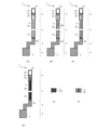
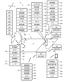
- FIG. 1A is a perspective view illustrating a golf club as a first embodiment
- FIG. 1B is a perspective view for explaining a modified example of a hosel in the golf club as the first embodiment
- 1A to 1C are perspective views illustrating different types of golf club heads.
- 11A to 11F are perspective views illustrating modified examples of the connection between the hosel and the shaft of a golf club.
- 11A to 11D are perspective views for explaining modified examples of the hosel of the golf club.
- 1A to 1C are cross-sectional views illustrating the internal structure of the golf club shown in FIG. 1A to 1C are cross-sectional views illustrating the internal structure of the golf club shown in FIG.
- FIGS. 7A and 7B are cross-sectional views for explaining a modified example of the internal structure of the golf club shown in FIG. 7A and 7B are cross-sectional views for explaining a modified example of the internal structure of the golf club shown in FIGS. 7A and 7B.
- 11A to 11C are cross-sectional views illustrating modified examples of the internal structure of a golf club.
- 9A and 9B are cross-sectional views for explaining modified examples of the internal structure of the golf club shown in FIGS. 9B and 9C.
- 10A and 10B are cross-sectional views for explaining a modified example of the internal structure of the golf club shown in FIG. 11A and 11B are cross-sectional views for explaining a modified example of the internal structure of the golf club shown in FIGS.
- 13A to 13C are explanatory diagrams illustrating modified examples of the internal structure of a golf club.
- 11A and 11B are cross-sectional views illustrating modified examples of the vibration transmitting member.
- 13A to 13G are explanatory diagrams illustrating modified examples of the vibration transmitting member.
- 11A to 11F are cross-sectional views illustrating modified examples of the vibration transmitting member.
- 11A and 11B are cross-sectional views illustrating modified examples of the vibration transmitting member.
- 11A to 11D are cross-sectional views for explaining modified examples of the golf club.
- 13A to 13E are explanatory diagrams illustrating modified examples of a hosel of a golf club.
- 11A to 11E are cross-sectional views illustrating modified examples of the vibration transmitting member.
- FIG. 11 is a cross-sectional view for explaining a modified example of the internal structure of the golf club.
- 13A and 13B are perspective views for explaining modified examples of the golf club head.
- FIG. 13 is a perspective view for explaining a modified example of a golf club.
- 24 is an explanatory diagram for explaining a modified example of the golf club shown in FIG. 23.
- 13A and 13B are explanatory diagrams for explaining modified examples of golf clubs.
- 1 is a block diagram for explaining a configuration of a golf practice system to which a golf club is applied.
- 13A and 13B are explanatory diagrams for explaining modified examples of golf clubs.
- 13A to 13E are explanatory diagrams for explaining modified examples of the golf club.
- 13A to 13D are explanatory diagrams for explaining modified examples of the golf club.
- 13A to 13D are explanatory diagrams for explaining modified examples of the golf club.
- 13A to 13F are explanatory diagrams for explaining a detachable unit of a vibration transmission member/tuning fork type sound generating body.
- 13A to 13E are explanatory diagrams for explaining modified examples of the golf club.
- FIG. 25 is a processing block diagram relating to the golf club of FIGS. 23 and 24.
- FIG. 23 is a processing block diagram relating to the golf club of FIG. 22.
- 13A and 13B are explanatory diagrams for explaining modified examples of golf clubs.
- FIG. 36 is a processing block diagram relating to the golf club of FIG. 35.
- 13A to 13C are explanatory diagrams for explaining modified examples of the golf club.
- 13A and 13B are explanatory diagrams of modified examples of the detachable unit.
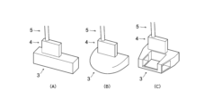
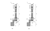
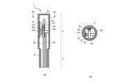
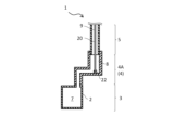
- Structure 1A is a perspective view illustrating a golf club 1 (putter) according to a first embodiment.
- the golf club 1 includes a head 3, a hosel 4, a shaft 5, and a grip 6.
- a striking surface 2 (face) for striking a golf ball is provided on the side of the head 3.
- the hosel 4 is a joint member that connects the lower end (one end) of the shaft 5 to the head 3. By connecting the lower end of the shaft 5 to the head 3 via the hosel 4, it is easier to connect the lower end of the shaft 5 to the head 3 than in a structure without a hosel.
- the shape of the hosel 4 is not particularly limited, and may be any well-known shape. In the golf club 1 of FIG.
- hosel 4 As an example of the hosel 4, a crank-shaped hosel 4A having a first bent portion 4F and a second bent portion 4R (two bent portions) at the intermediate portion between the upper end 4U and the lower end 4D is provided.
- a flat hosel 4B that extends in a plane direction parallel to the striking surface 2 and is formed in a rectangular flat plate shape having a certain thickness is provided.
- hosel 4" is used as a general term for hosels of various shapes, except when it is necessary to distinguish them.
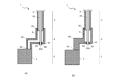
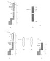
- FIGS. 2(A)-(C) are perspective views illustrating various types of putter heads 3.
- the shape of the head 3 may be a pin type as shown in FIG. 2(A), a mallet type as shown in FIG. 2(B), or a neo-mallet type as shown in FIG. 2(C).
- FIGS. 2(A)-(C) show a golf club 1 having a flat hosel 4B as shown in FIG. 1(B) as an example, but the shape of the hosel 4 may be any, including the crank-shaped hosel 4A in FIG. 1(A).
- the shaft 5 is formed in an axial shape (a long, thin rod), and one end (the lower end in FIG. 1) is connected to the head 3 via the hosel 4.
- the shape of the lower end of the shaft 5 fixed to the hosel 4 may be straight as shown in FIGS. 1(A) and (B), or may be crank-shaped (see FIG. 4(A) below) with two or more bends and with the upper end positioned further forward than the lower end, or may be bent (curved).
- the direction in which the striking surface 2 faces when using the golf club 1 is referred to as the "forward" direction
- the opposite side is referred to as the "rearward" direction.
- the cross-sectional shape of the shaft 5 may be circular, elliptical, or polygonal.
- a grip 6, which is the part to be held by the user, is provided at the other end (the upper end in FIG. 1) of the shaft 5.
- the cross-sectional shape of the grip 6 may be circular, elliptical, or polygonal.
- the hosel 4 is formed integrally with the head 3 and the shaft 5 in a non-replaceable state, for example.
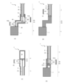
- Figures 3(A) to 3(F) are perspective views for explaining several specific examples of the connection form between the rectangular flat hosel 4B (hosel 4) and the shaft 5.
- the shaft 5 may be connected to the end face of the hosel 4 as shown in Figure 3(A), or may be connected to the plate surface of the hosel 4 as shown in Figure 3(B).
- the thickness of the hosel 4 (dimension in the plate thickness direction) can be set regardless of the thickness of the shaft 5.
- the cross-sectional area of the lower end of the shaft 5 may be processed to be smaller as shown in Figure 3(C).
- the hosel 4 may be provided detachably with respect to the head 3 and the shaft 5.
- the width dimension of the hosel 4 when viewed from the front can also be set independently of the thickness of the shaft 5.
- the width dimension of the hosel 4 may be set to a dimension approximately equal to the thickness of the shaft 5.
- the hosel 4 may be formed so that the width dimension is smaller only at the upper end connected to the shaft 5.
- the width dimension of the upper end of the hosel 4 may be set to a dimension approximately equal to the thickness of the shaft 5.
- the upper end of the hosel 4 may be made thinner than the shaft 5.
- the orientation of the hosel 4 fixed to the head 3 is set so that it extends in a planar direction parallel to the striking surface 2.
- the hosel 4 may be arranged parallel to the striking surface 2.
- the flat hosel 4 may be arranged tilted at an angle (for example, with the upper part tilted toward the striking surface 2).
- the shape of the lower end of the shaft 5 fixed to the hosel 4 may be crank-shaped, as shown in FIG. 4(A), or straight, or bent (curved) in shape.
- the hosel 4 may be formed in a flat plate shape or a curved plate shape. If it is formed in a flat plate shape, it may be formed in a rectangular plate shape as shown in FIG. 4(A) or a polygonal (triangular or pentagonal) plate shape. If it is formed in a curved plate shape, it may be curved so that the side closer to the striking surface 2 is on the inside in a longitudinal cross section perpendicular to the striking surface 2 as shown in FIG. 4(C), or it may be curved so that the side closer to the striking surface 2 is on the outside.
- the hosel 4 may be formed in a flat irregular quadrilateral shape that imitates the side shape of a horseshoe as shown in FIG. 4(D).
- the hosel 4 and head 3 may be arranged so as to be flush with the striking surface 2 (forming the same plane) as shown in FIG. 1(B), or may be arranged so as to be non-flush with the striking surface 2 (the hosel 4 is arranged behind the striking surface 2) as shown in FIG. 3(A)-(F). It goes without saying that even in the various examples of how the hosel 4 and head 3 are arranged, such as FIG. 3(A)-(F), the hosel 4 and head 3 may be arranged so as to be flush with the striking surface 2 as shown in FIG. 1(B).
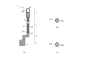
- hosel 4, shaft 5, and grip 6 included in the golf club 1 are each formed to be hollow (having a cavity inside).
- the head 3 and the hosel 4 may each be formed to be hollow (having a cavity inside) or solid (having no cavity inside).
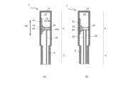
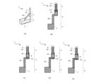
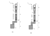
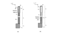
- 5(A), (B), and (C) are cross-sectional views showing the longitudinal section of the golf club 1 in FIG. 1(A), and show an example in which the shaft 5 and the grip 6 are each hollow, and the crank-shaped hosel 4A (hosel 4) and the shaft 5 are each solid.
- the golf clubs 1 shown in Figures 5(A), (B), and (C) are the same except for the manner in which the hosel 4 and shaft 5 are connected. Specifically, in the golf club 1 of Figure 5(A), the upper end of the hosel 4 and the lower end of the shaft 5 are butted together and connected. In the golf club 1 of Figure 5(B), the inner circumference of the upper end of the hosel 4 is set to be larger than the outer circumference of the lower end of the shaft 5, and the lower end of the shaft 5 is inserted into the upper end of the hosel 4 and connected.
- the outer circumference of the upper end of the hosel 4 is set to be smaller than the inner circumference of the lower end of the shaft 5, and the upper end of the hosel 4 is inserted into the lower end of the shaft 5 and connected.
- the shaft 5 has a hollow shaft cavity 9 (first cavity) therein, and the grip 6 has a hollow grip cavity 10 (second cavity) therein that communicates with the shaft cavity 9. Both the upper and lower ends of the shaft 5 are open. The upper end of the grip 6 is closed by a grip upper end plate 21 that forms the grip end, and the lower end is open. The shaft cavity 9 and the grip cavity 10 communicate with each other.
- the head 3 and the hosel 4 are formed of a solid material having a compact cross section.
- a vibration transmission member 20 is built into the golf club 1.
- the vibration transmission member 20 is a member that transmits vibrations generated on the striking surface 2 to the grip 6.
- the vibration transmission member 20 is formed in a long shape and is provided inside the shaft cavity 9 and the grip cavity 10.
- Specific examples of the vibration transmission member 20 include wires (e.g., steel wires and piano wires), strings (e.g., strings made by weaving various fibers, wide belts, and mesh-like belts), rod members (e.g., rod members made of rod-shaped metal or wood), linear elastic members (e.g., linear elastic members made of rubber or resin), and long coil springs.
- fibers include cellulose, nanocellulose, and cellulose nanofibers.
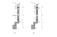
- 5A, 5B and 5C show an example in which the vibration transmission member 20 is formed of a rod member.
- the vibration transmission member 20 is directly fixed to the hosel 4 via a fixing device 22. Meanwhile, the other end of the vibration transmission member 20 (the upper end in Figs. 5A, 5B, and 5C) is attached to the inner peripheral surface of the grip 6 via an inner grip plate 23 and an inner grip fixing device 24 (attaching member).
- the fixing device 22 is, for example, a member attached to the upper end 4U of the hosel 4, and may have any structure as long as it can fix the lower end of the vibration transmission member 20. In this case, the vibration transmission member 20 is arranged in a straight line between the fixing device 22 and the inner grip fixing device 24.
- a mass member 26 that serves as a weight for amplifying vibration may be attached to the vibration transmission member 20, as shown by the dashed line in Fig. 5A.
- the position of the mass member 26 may be fixed relative to the vibration transmission member 20, or may be movable (the fixing position may be adjustable). In addition, for example, the mass member 26 may be added according to the user's preference.
- the mass member 26 may be attached to any golf club 1, not limited to the golf club 1 shown in FIG. 5(A).
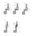
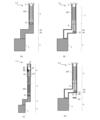
- the golf clubs 1 shown in Figures 6(A), (B), and (C) are the same as the golf clubs 1 shown in Figures 5(A), (B), and (C), except that they have a flat hosel 4B as the hosel 4. That is, in the golf clubs 1 shown in Figures 6(A), (B), and (C), one end of the vibration transmission member 20 disposed inside the shaft cavity 9 and the grip cavity 10 is fixed to the flat hosel 4B via a fixing device 22.
- FIG. 7A and 7B show an example of the configuration of a golf club 1 in which the inside of a crank-shaped hosel 4A (hosel 4) is formed to be hollow.
- a hosel cavity 8 (third cavity) is provided inside the hosel 4.
- the hosel 4 shown in Fig. 7A is provided with the hosel cavity 8 formed to communicate between the upper end 4U and the lower end 4D.
- the hosel cavity 8 has a crank shape having two bent portions corresponding to the two bent portions 4F, 4R of the crank-shaped hosel 4A.
- the hosel 4 shown in FIG. 7(B) has a hosel cavity 8 in a portion of the hosel 4 located on the shaft 5 side (upper side), and the remaining portion of the hosel 4 excluding the portion on the shaft 5 side (upper side) is formed solid.
- the hosel 4 shown in FIG. 7(B) has a hosel cavity 8 from the upper end 4U to the first bend 4F, and the portion located closer to the head 3 than the first bend 4F, i.e., the portion including the second bend 4R and the lower end 4D, is formed solid.
- the hosel cavity 8 is formed in a straight line from the upper end 4U to the first bend 4F.
- FIGS 7(A) and (B) show an example in which one end of the vibration transmission member 20 is fixed to the inner peripheral surface of the hosel cavity 8 via a fixing device 22.
- the fixing device 22 is disposed at the first bend 4F on the surface 8A of the inner peripheral surface of the hosel cavity 8 that faces the upper end 4U.
- one end of the vibration transmission member 20 is fixed below the upper end 4U of the hosel 4 within the hosel cavity 8.
- vibrations generated on the striking surface of the head 3 are not only transmitted to the grip 6 via the hosel 4 and shaft 5, but also to the grip 6 via the hosel 4 and vibration transmission member 20.
- the vibration transmission member 20 into the shaft 5 and grip 6, the vibration transmission path can be increased, and vibrations generated on the striking surface of the head 3 can be efficiently transmitted to the grip 6 without attenuation. Therefore, a good hitting feel can be provided to the user, and the hitting feel can be improved compared to existing golf clubs.
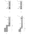
- FIG. 8(A) and (B) are modified versions of the golf club 1 shown in FIG. 7(A) and (B), and the mounting structure of the lower end (one end) of the vibration transmission member 20 is different from that of FIG. 7(A) and (B).
- a hole 8B that connects the hosel cavity 8 to the outside is provided at the first bent portion 4F, on the surface 8A of the inner circumferential surface of the hosel cavity 8 that faces the upper end 4U.
- the hole 8B is a mounting hole for the vibration transmission member 20.
- the vibration transmission member 20 is inserted into the hosel cavity 8 from the outside of the hosel 4 through the hole 8B.
- the lower end 20D of the vibration transmission member 20 is formed wider than the diameter of the hole 8B, and the lower end 20D of the vibration transmission member 20 is engaged and attached on the outside of the hole 8B.
- the grip inner plate 23 and the grip inner fixture 24 (mounting member) provided at the other end (upper end in the figure) of the vibration transmission member 20 may be provided so as to be adjustable in position in the extension direction of the grip 6.
- the grip inner plate 23 may be formed in a membrane shape that is deployed in a direction intersecting the extension direction of the grip 6 (for example, a direction perpendicular to the extension direction of the grip 6).
- FIGS. 9A and 9B show modified examples of the golf club 1 shown in each of the above-mentioned golf clubs 1, in which the mounting structure of the upper end (other end) of the vibration transmission member 20 is different.
- the other end (the upper end in the figure) of the vibration transmission member 20 is attached to the inner surface of the grip 6 via a grip upper end plate 21 and a grip inner fixing device 24 (mounting member).
- a motor 43 and a winding device 44 are provided at the other end (upper end in the figure) of the vibration transmission member 20.
- the motor 43 and the winding device 44 are mechanisms for making it possible to adjust the position of the other end of the vibration transmission member 20 in the extending direction of the grip 6.
- the vibration transmission member 20 is formed of a windable member, and specifically, is composed of any one of a wire, a string, a linear elastic member, and a long coil spring.
- Fig. 9(C) is a cross-sectional view of the golf club 1 taken along line X1-X1 in Fig. 9(B).
- the winding device 44 is formed of a rod-shaped body extending along the cross section of the grip 6, and a motor 43 is connected to one end of the rod-shaped body.
- a pinion 42 is rotatably attached to the motor 43.
- a rack 41 that meshes with the pinion 42 is fixed to the inner circumferential surface of the grip cavity 10.
- the pinion 42 is urged upward relative to the rack 41 by a urging member (e.g., a spring or rubber) (not shown).
- the pinion 42 moves downward along the rack 41 by rotating the motor 43 and winding up the other end of the vibration transmission member 20 with the winding device 44.
- the pinion 42 moves upward along the rack 41 by rewinding the motor 43.
- a manually operated winding device 44 may be used instead of the motor 43.
- the winding device 44 may be provided so as to be rotated from the outside using a tool such as a Phillips screwdriver or a flathead screwdriver.
- the pinion 42 moves downward along the rack 41 by manually rotating the winding device 44 to wind up the other end of the vibration transmission member 20.
- the pinion 42 moves upward along the rack 41 by rewinding the winding device 44 in the opposite direction.
- the rack and pinion may be omitted, and a mechanism for adjusting the tension of the vibration transmission member 20 may be formed by winding/releasing the other end of the vibration transmission member 20 using a motor 43 and a winding device 44.
- the golf club 1 shown in FIG. 10(A) is a modified version of the golf club 1 shown in FIG. 9(B), and has an adjustment mechanism 44A (shown by a dashed line in the figure) that adjusts the position of the vibration transmission member 20 along a transverse direction that intersects with the extension direction of the grip 6.
- the transverse direction adjustment mechanism 44A is built into the winding device 44, and includes, for example, a rack along the transverse direction, a pinion meshed with the rack, and a motor that rotates the pinion.
- the position of the other end of the vibration transmission member 20 can be adjusted along the transverse direction indicated by the arrow CX in the figure.
- the golf club 1 shown in Fig. 10(B) is another modified example of the golf club 1 shown in Fig. 9(B).
- two (plural) vibration transmission members 20, 20' are provided in parallel with respect to a set of a rack 41, a pinion 42, a motor 43, and a winding device 44.
- the other ends (upper ends in the figure) of the two vibration transmission members 20, 20' are attached in parallel with one winding device 44.
- One end (lower end, not shown) of each of the two vibration transmission members 20, 20' is attached to a fixture 22 (Fig. 5(A) etc.). In this case, one fixture 22 (Fig.
- vibrations may be transmitted to the shaft 5 and grip 6 more efficiently, allowing the user to feel accurate and delicate vibrations.
- the golf club 1 shown in Figures 11(A) and (B) is a modified version of the golf club 1 shown in Figure 10(B), and has two (multiple) sets of racks 41, 41', pinions 42, 42', motors 43, 43', and winding devices 44, 44' corresponding to two (multiple) vibration transmission members 20, 20'.
- Figure 11(B) is a cross-sectional view of the golf club 1 taken along line X2-X2 in Figure 11(A). As shown in Figure 11(B), the winding devices 44, 44' are arranged in parallel to each other.
- the golf club 1 shown in Figures 12(A) and (B) is a modified version of the golf club 1 shown in Figures 11(A) and (B), and the arrangement of the two sets of racks 41, 41', pinions 42, 42', motors 43, 43', and winding devices 44, 44' is different from that in Figures 11(A) and (B).
- the two sets of racks 41, 41', pinions 42, 42', motors 43, 43', and winding devices 44, 44' are arranged in such a manner that the winding devices 44, 44' cross each other.
- Figure 12(B) is a cross-sectional view of the golf club 1 taken along line X3-X3 in Figure 12(A).
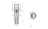
- FIGS 13B and 13C are plan views of the upper mounting member 27U and the lower mounting member 27D, respectively, viewed from the extending direction of the vibration transmitting members 20 and 20'.
- each of the upper mounting member 27U and the lower mounting member 27D is formed of a circular plate-like member having a surface that intersects with the extension direction of the vibration transmission members 20, 20'.
- each of the upper mounting member 27U and the lower mounting member 27D is disposed in such a manner that its plate surface intersects with the extension direction of the vibration transmission members 20, 20' and is parallel to each other.
- the upper mounting member 27U and the lower mounting member 27D each have a plurality of connecting holes 28U, 28D penetrating from one surface of the plate to the other surface.
- the connecting holes 28U, 28D are connecting portions for connecting the ends of the vibration transmission members 20, 20'.
- One end of vibration transmission member 20 is connected to one connecting hole 28D in lower mounting member 27D, and one end of vibration transmission member 20' is connected to another connecting hole 28D in lower mounting member 27D.
- the other end of vibration transmission member 20 is connected to one connecting hole 28U in upper mounting member 27U, and the other end of vibration transmission member 20' is connected to another connecting hole 28U in upper mounting member 27U.
- the vibration transmission members 20, 20' can be attached to the connecting holes 28U, 28D of the upper mounting member 27U and the lower mounting member 27D, one each. Therefore, multiple vibration transmission members 20, 20' can be provided in the same number of connecting holes 28U, 28D. It is preferable that the connecting holes 28U, 28D to which the vibration transmission members 20, 20' are attached are arranged in a straight line so that the multiple vibration transmission members 20, 20' are parallel to each other. In this case, since the multiple vibration transmission members 20, 20' are arranged in a forest, it can be said that the multiple vibration transmission members 20, 20' are arranged in a harp shape.
- the upper attachment member 27U may be attached to the grip upper end plate 21 (grip end).
- the grip upper end plate 21 itself may function as the upper attachment member 27U, that is, the grip upper end plate 21 may be provided with a plurality of connection holes 28U.
- the lower mounting member 27 ⁇ /b>D may be attached to the inner peripheral surface of the hosel 4 within the hosel cavity 8 .
- the lower mounting member 27D may be combined with the winding device 44. In this case, the lower ends of the vibration transmission members 20, 20' are attached to the lower mounting member 27D, and the upper ends are attached to the winding device 44.
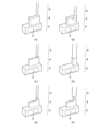
- Figures 14(A) and (B) are explanatory diagrams of modified examples of the vibration transmission member 20.
- the golf club 1 shown in Figures 14(A) and (B) differs from the golf club 1 shown in Figure 5(A) in the shape of the vibration transmission member 20, but other features are common to the golf club 1 shown in Figure 5(A).
- 14A shows a vibration transmission member 20 having a wide portion 20A in the middle in the extending direction.
- the wide portion 20A is a portion formed wider than its upper and lower portions.
- the wide portion 20A can adjust the vibration transmission characteristics of the vibration transmission member 20 and improve the hitting feel.
- ⁇ Tuning fork type> 14B shows a vibration transmission member 20 having a tuning fork shape with an upper portion split into two (U-shape).
- one in-grip fixing device 24 is provided corresponding to each of the upper ends of the bifurcated vibration transmission member 20.
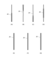
- ⁇ Tuning fork type, Y-shaped, ring type> 15A to 15G show examples of various shapes of the vibration transmission member 20.
- the vibration transmission member 20 is configured as a rod member.
- the vibration transmission member 20 shown in Fig. 15(A) has a tuning fork shape with a bifurcated (U-shaped) lower portion. In other words, it has a shape obtained by turning upside down the vibration transmission member 20 shown in Fig. 14(B).
- fixing devices 22 Fig. 5(A) etc.
- the vibration transmission member 20 shown in Figures 15(B) and (C) is Y-shaped.
- the vibration transmission member 20 in Figure 15(B) is Y-shaped with an upper portion split into two
- the vibration transmission member 20 in Figure 15(C) is Y-shaped with a lower portion split into two.
- the vibration transmission member 20 shown in Fig. 15(D) has a shape having a ring-shaped portion in the middle in the extension direction.
- the vibration transmission member 20 shown in Fig. 15(E) is formed in a ring shape as a whole, and differs from the vibration transmission member 20 shown in Fig. 15(D) in that there are no line portions on either the top or bottom.
- the vibration transmission member 20 shown in Fig. 15(F) and (G) is a modified example of the tuning fork type vibration transmission member 20 shown in Fig. 14(B) and Fig. 15(A), and is formed in a U-shape as a whole.
- the vibration transmission members 20 shown in Figures 15(A) to (G) can provide the user with a better hitting feel by adjusting the vibration transmission characteristics of the vibration transmission member 20 or emphasizing the vibration depending on the shape.
- the shapes of the vibration transmission members 20 shown in Figures 15(A) to (G) are examples and are not limited to those shown.
- the entire vibration transmission member 20 may be formed in a V-shape.
- the upper or lower portion of the vibration transmission member 20 may be branched into three or more branches.
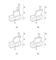
- the golf club 1 shown in Figures 16(A) and (B) is an example in which the vibration transmission member 20 is made of a wire or string.
- the wire is, for example, a steel wire or a piano wire.
- the string includes various shapes of string-like bodies, such as a string made by weaving various fibers, a wide belt string, a mesh-like belt string, and a membrane-like belt string.
- the vibration transmission member 20 shown in Figure 16(A) the lower end of a single wire or string constituting the vibration transmission member 20 is fixed to a fixture 22, and the upper end thereof is fixed to a fixture 24 inside the grip.
- the vibration transmission member 20 shown in Fig. 16(B) has a plurality of sound-producing bodies 20S attached along the extending direction of the wire or string.
- Each sound-producing body 20S is an object that produces a sound by the vibration of the vibration transmission member 20.
- Examples of the sound-producing body 20S include bells, beads, pieces of wood, pieces of metal, and vibrating plates.
- structures that produce sound using a vibration transmission member 20 made of wire or string are not limited to structures that use a sound-producing body 20S, and can also include structures (such as a mukkuri or mouth harp type) in which the sound generated by the vibration of the vibration transmission member 20 resonates within the shaft hollow portion 9 and the grip hollow portion 10.
- the golf club 1 shown in FIG. 16(C) is an example in which the vibration transmission member 20 is configured as a chain.
- a chain is a chain member in which ring-shaped parts are linearly connected.
- the ring-shaped parts that make up the chain may have any known shape or connection form. Examples of the types (shapes) of chains include chain-shaped, armor-shaped, snake-shaped, and scale-shaped.
- ⁇ Coil spring> 16(D) shows an example of a golf club 1 in which the vibration transmission member 20 is configured with a long coil spring.
- the lower end of the coil spring constituting the vibration transmission member 20 is fixed to a fixture 22, and the upper end of the coil spring is fixed to a fixture 24 inside the grip.
- the coil spring constituting the vibration transmission member 20 may be arranged with its outer periphery in contact with the inner periphery of the shaft hollow portion 9 as shown in FIG. 16(E), or may be arranged with its outer periphery spaced apart from the inner periphery of the shaft hollow portion 9 as shown in FIG. 16(F).
- the vibration transmission member 20 may be formed of any combination (a structure formed by combining a plurality of members) of a wire, a string, a rod member, a linear elastic member, or a long coil spring.
- the vibration transmission member 20 shown in Fig. 17(A) is formed by connecting a coil spring 20C to both the upper and lower sides of a rod member 20R.
- the tuning fork type vibration transmission member 20 shown in Fig. 17(B) is attached to a fixture 22 and a fixture 24 inside the grip via a wire 20W.
- the vibration transmission member 20 is constructed by combining a plurality of members, the length ratio of each member may be freely determined.
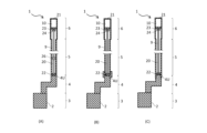
- the golf club 1 shown in FIGS. 18A to 18D is an example in which the internal spaces of the cavities 8, 9, and 10 have openings that communicate with the outside.
- the golf club 1 shown in Fig. 18(A) is a modified version of the golf club 1 shown in Fig. 7(A).
- the crank-shaped hosel 4A (hosel 4) of this golf club 1 is provided with two openings 80A, 80B that connect the internal space of the hosel cavity 8 with the outside.
- the openings 80A, 80B are disposed at different positions.
- the opening 80A is provided between the upper end 4U and the first bent portion 4F.
- the opening 80B is provided between the second bent portion 4R and the lower end 4D.
- Each of the openings 80A, 80B can be closed with a lid 81A, 81B.
- Each of the openings 80A, 80B can be considered a covered inspection window for visually checking the state inside the hosel cavity 8 (hosel 4) from the outside.
- the user closes the openings 80A, 80B with the lid 81A, 81B, and when inspecting the inside, removes the lid 81A, 81B and opens the openings 80A, 80B.
- One item that can be checked is the installation state of the vibration transmission member 20.
- the openings 80A and 80B enable the reverberation generated within the hosel cavity 8 (hosel 4) when the head 3 hits a ball to be transmitted to the outside of the hosel 4. This makes it possible to increase the volume of the sound that reaches the user's ears when the head 3 hits a ball, thereby further improving the feel of the hit.
- the openings 80A and 80B which form inspection windows, also serve as openings for transmitting the reverberation within the hosel 4 to the outside.
- the golf club 1 in Figure 18 (A) is shown as an example having two openings 80A, 80B, the number of openings arranged in the hosel 4 may be one or more, and the locations of the openings may be set arbitrarily.
- the shaft 5 of the golf club 1 shown in FIG. 18(B) has an opening 90 that connects the internal space of the shaft cavity 9 to the outside.
- the grip 6 of the golf club 1 shown in FIG. 18(C) has an opening 92 that connects the internal space of the grip cavity 10 to the outside.
- the openings 90, 92 function as covered inspection windows that can be closed with covers 91, 93. During normal use other than inspection, the user closes the openings 90, 92 with the covers 91, 93, and when inspecting the inside of the shaft 5 or the grip 6, removes the covers 91, 93 to open the openings 90, 92.
- These openings 90, 92 also serve as openings for transmitting reverberation from the inside of the shaft 5 or the grip 6 to the outside.
- the golf club 1 shown in FIG. 18(D) is a modified version of the golf club 1 shown in FIG. 1(B).
- the hosel 4B (hosel 4) of this golf club 1 is formed in a rectangular flat plate shape and has a hosel cavity 8 therein, with an opening 80 that connects the internal space of the hosel cavity 8 to the outside.
- the opening 80 functions as a covered inspection window that can be closed with a lid 81, and also serves as an opening for transmitting reverberation from within the hosel 4 to the outside.
- the fixture 22 that fixes the lower end of the vibration transmission member 20 is attached to a fixing plate 22A attached to the inside of the hosel cavity 8.
- the golf club 1 in Figures 19(A) to (E) is a modified example of the shape of the hosel 4.
- the hosel 4 is formed by combining a trapezoidal portion 4X that is trapezoidal (or substantially triangular) when viewed from the front and a crank-shaped portion 4Y that extends upward from the upper part of the trapezoidal portion 4X.
- the crank-shaped portion 4Y has two bent portions in the middle part in the extending direction.
- the head 3 is provided below the trapezoidal portion 4X
- the shaft 5 is provided above the crank-shaped portion 4Y.
- the golf club 1 shown in FIG. 19(C) differs from the golf club 1 shown in FIG. 19(B) in that it has a hosel cavity 8 in part of the crank-shaped portion 4Y. That is, the hosel cavity 8 is provided in part of the upper end side of the crank-shaped portion 4Y, and the rest of the crank-shaped portion 4Y except for the part where the hosel cavity 8 is provided is made of a solid material with a solid cross-section. In this case, the lower end of the vibration transmission member 20 is fixed to the inner surface of the hosel cavity 8 via a fixing device 22.
- the golf club 1 shown in FIG. 19(D) differs from the golf club 1 shown in FIG. 19(C) in that a hosel cavity 8 is provided over the entire length of the crank-shaped portion 4Y.
- the hosel cavity 8 is formed to connect the upper and lower ends of the crank-shaped portion 4Y.
- the lower end of the vibration transmission member 20 is fixed to the inner surface of the hosel cavity 8 via a fixing device 22.
- the golf club 1 shown in FIG. 19(E) differs from the golf club 1 shown in FIG. 19(D) in that a hosel cavity 8 is provided in both the trapezoidal portion 4X and the crank-shaped portion 4Y that form the hosel 4.
- the lower end of the vibration transmission member 20 is fixed to the inner peripheral surface of the hosel cavity 8 via a fixing device 22.
- the hosel cavity 8 is formed so as to communicate between the cavity in the trapezoidal portion 4X and the cavity in the crank-shaped portion 4Y, but the cavity in the trapezoidal portion 4X and the cavity in the crank-shaped portion 4Y may be separated and not communicate with each other.
- the golf clubs 1 shown in Figures 20(A) to (E) are modified examples with respect to the configuration of the vibration transmission member 20.
- Each of the golf clubs 1 in Figures 20(A) to (C) has a crank-shaped hosel 4A similar to that in Figure 7(A), but the vibration transmission member 20 is different from that in Figure 7(A).
- the vibration transmission member 20 has one bending point 29 and is bent at one point.
- the first vibration transmission member 20X which is a portion of the vibration transmission member 20 that extends upward from the bending point 29, extends in the up-down direction.
- the second vibration transmission member 20Y which is a portion of the vibration transmission member 20 that extends rearward from the bending point 29, extends in the front-rear direction.
- the first vibration transmission member 20X and the second vibration transmission member 20Y are configured as rod members.
- the vibration transmission member 20 differs from that of FIG. 20(B) in that the second vibration transmission member 20Y extending rearward from the bending point 29 is composed of a long coil spring.
- the golf club 1 in Fig. 20(C) has an auxiliary vibration transmission member 20Z attached in the hosel cavity 8, and the vibration transmission member 20 is attached to this auxiliary vibration transmission member 20Z via a connection part 20K.
- the auxiliary vibration transmission member 20Z is disposed in the hosel cavity 8 in the crank-shaped hosel 4A in a posture extending in the front-rear direction, and both ends of the auxiliary vibration transmission member 20Z are fixed to the inner peripheral surface of the hosel cavity 8 via fasteners.
- One end (the lower end in the figure) of the vibration transmission member 20 is attached to the auxiliary vibration transmission member 20Z.
- the vibration transmission member 20 is indirectly fixed to the hosel 4 via the auxiliary vibration transmission member 20Z.
- the auxiliary vibration transmission member 20Z shown in Figure 20(C) may be attached to a hosel cavity 8 provided inside a flat hosel 4B (hosel 4) as shown in Figure 18(D). In this case as well, a good hitting feel can be provided to the user, and the hitting feel can be improved compared to existing golf clubs.
- the golf club 1 shown in Figures 20(D) and (E) has a hosel 4 that combines a trapezoidal portion 4X and a crank-shaped portion 4Y similar to that of Figure 19(D), and differs from Figure 19(D) in that a hosel cavity 8 is provided within the crank-shaped portion 4Y and across the upper portion (part) of the trapezoidal portion 4X.
- the vibration transmission member 20 has two bending points 29 and is bent in two places along the bending shape of the hosel cavity 8.
- the vibration transmission member 20 is composed of a rod member 20R and a coil spring 20C.
- the rod member 20R is disposed in the grip cavity (not shown) and the shaft cavity 9, and the coil spring 20C is disposed in the hosel cavity 8.
- the upper end of the coil spring 20C is connected to the lower end of the rod member 20R, and the lower end of the coil spring 20C is fixed to the upper part of the trapezoidal portion 4X.
- the coil spring 20C is disposed in the hosel cavity 8 in a shape that is bent in two places along the bent shape of the crank-shaped portion 4Y.
- ⁇ Weight material> 22A and 22B are perspective views for explaining modified examples of the head 3.
- the head 3 may have a built-in weight member 61 for changing the position of the center of gravity of the head 3.
- the center of gravity may be changed by making the mounting state (position and angle) of the weight member 61 adjustable.
- the mounting state of the weight member 61 may be manually adjustable by the user, or a weight motor 62 (drive source) for moving the weight member 61 may be provided.
- the golf club 1 provided with the weight member 61 has a head 3, a hosel 4, a shaft 5, and a grip, the grip 6 is integrally formed with the shaft 5, a vibration transmission member 20 is built in a shaft cavity 9 in the shaft 5 and a grip cavity 10 in the grip 6, the lower end of the vibration transmission member 20 is fixed to the hosel 4, and the grip cavity 10 has mounting members (grip inner plate 23 and grip inner fixing device 24) that connect the upper end of the vibration transmission member 20 to the grip 6 inside the grip cavity 10.
- Figure 22 (A) is a perspective view showing two sets of weight members 61 and a weight motor 62 built into the top surface of the head 3.
- the weight members 61 are made of a material with a different density than the material constituting the head 3, and are provided inside a hollow cylindrical recess formed in the top surface of the head 3.
- the weight motor 62 moves the weight members 61 in the rotational direction along the inner surface of the recess, thereby changing the position of each weight member 61. With this configuration, the position of the weight members 61 can be easily changed to move the center of gravity of the head 3, providing a good hitting feel.
- FIG. 22(B) is a perspective view showing weight members 61 provided inside a linear recess formed in the top surface of the head 3.
- the weight motor 62 changes the position of each weight member 61 by sliding the weight members 61 along the inner peripheral surface of the recess. Even with this configuration, the position of the weight members 61 can be easily changed to move the center of gravity of the head 3, providing a good hitting feel.
- Fig. 23 is a perspective view of the golf club 1 according to this modification.
- the basic configuration of the golf club 1 in Fig. 23 is the same as that of the golf club 1 shown in Fig. 1(B) above, and includes a head 3, a hosel 4, a shaft 5, and a grip.
- the grip 6 is formed integrally with the shaft 5.
- a vibration transmission member 20 is built into the shaft cavity 9 in the shaft 5 and the grip cavity 10 in the grip 6. The lower end of the vibration transmission member 20 is fixed to the hosel 4.
- the grip cavity 10 has an attachment member (grip inner plate 23 and grip inner fixing member 24) that connects the upper end of the vibration transmission member 20 to the grip 6.
- the golf club 1 may include a vibration sensor 95 built into the hosel 4 to detect vibrations transmitted from the hosel 4 to the vibration transmission member 20.
- the vibration sensor 95 may be attached to the outer surface of the hosel 4 or may be built into the hosel 4. If a hosel cavity 8 is formed inside the hosel 4, the vibration sensor 95 may be disposed inside the hosel 4.
- a vibration device 96 (actuator) that vibrates based on vibration information detected by the vibration sensor 95 may be built into the hosel 4. If a hosel cavity 8 is formed inside the hosel 4, the vibration device 96 may be disposed inside it.
- the vibration device 96 may function, for example, to directly amplify and output the vibration detected by the vibration sensor 95. By amplifying the vibration with the vibration device 96, it is possible to increase the vibration that is actually transmitted to the user, further improving the feel of the hit.
- a speaker 96A that emits sound based on information on vibrations detected by the vibration sensor 95 may be built into the hosel 4. If a hosel cavity 8 is formed inside the hosel 4, a speaker 96A including an amplifier may be placed inside it. The speaker 96A may function to amplify and output the vibrations detected by the vibration sensor 95 as sound, for example. In this way, when a golf ball is hit with one of the striking surfaces of the golf club, the vibrations at that time are detected by the vibration sensor 95 and can be heard as sound from the speaker 96A. At this time, the hollow hosel 4, shaft 5, and grip 6 function as a speaker box, amplifying and outputting the sound related to the vibrations. As a result, the golf club 1 can function as a kind of electronic musical instrument.
- another vibration device 97 (actuator) and speaker 97A may be built into the grip 6.
- the vibration device 97 and speaker 97A are disposed, for example, inside the grip cavity 10 in the grip 6.
- the vibration device 97 and speaker 97A function to directly amplify and output the vibrations detected by the vibration sensor 95, or to directly amplify and output the vibrations detected by the vibration sensor 95 as sound.
- the vibrations and sounds that are actually transmitted to the user can be made even larger, further improving the hitting feel.
- the golf club 1 may further include a transmitter 101 for transmitting information detected by the vibration sensor 95 to an outside.
- the transmitter 101 is built into, for example, the hosel 4. When a hosel cavity 8 is formed inside the hosel 4, the transmitter 101 may be disposed inside the hosel 4.
- the information detected by the vibration sensor 95 may be transmitted to an external device such as a computer (not shown) via the transmitter 101, for example, by wireless connection or wired connection.
- the golf club 1 may include a controller 100 having a rhythm box function and a synthetic voice generating function for informing the player of the rhythm when the golf ball is hit.
- the controller 100 is built into the hosel 4, for example. If a hosel cavity 8 is formed inside the hosel 4, the controller 100 may be disposed inside the hosel.
- a speaker 96A is connected to the output side of the controller 100. When the golf ball is hit, one of the rhythm sound and the synthetic voice generated by the controller 100 can be output from the speaker 96A by either the rhythm box function or the synthetic voice generating function of the controller 100. Note that the on/off of the rhythm box function and the synthetic voice generating function of the controller 100, volume adjustment, and other various operations can be input from an indicator (not shown).
- the indicator may be built into the golf club 1.
- the indicator may be configured by an external device (e.g., a smartphone) connected by wireless connection.
- the various functions of the controller 100 may be configured by an external device (e.g., a smartphone) connected by wireless connection.
- the golf club 1 shown in Fig. 24 is a modified example of the golf club 1 shown in Fig. 23.
- the vibration sensor 95, the vibration device 96, the speaker 96A, the transmitter 101, and the controller 100 built into the hosel 4 of the golf club 1 shown in Fig. 23 may be built into the shaft 5.
- 24 shows an example of a configuration in which a vibration sensor 95', a vibration device 96', and a speaker 96A' are further built into the shaft 5 of the golf club 1 shown in FIG. Without being limited to this, all of the vibration sensor, vibration device, speaker, transmitter, and controller may be built into the shaft 5.
- the vibration sensor, vibration device, speaker, transmitter, and controller may be built into only one of the hosel 4 and the shaft 5, or may be built into both. Also, some of the vibration sensor, vibration device, speaker, transmitter, and controller may be built into one of the hosel 4 and the shaft 5, and the rest may be built into the other of the hosel 4 and the shaft 5 (distributed or combined).
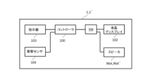
- a liquid crystal display 102 (display device, electric display member) may be added (display function).
- the liquid crystal display 102 is arranged, for example, on the surface facing the upper side of the head 3, and is connected to the output side of the controller 100.
- the liquid crystal display 102 can display the vibration data detected by the vibration sensors 95, 95' as numerical values, graphs, etc.
- the liquid crystal display 102 may also display the launch direction of the golf ball.
- the controller 100 controls the indicator (see reference numeral 103 in FIG. 33) to transmit an instruction signal for displaying the launch direction of the golf ball to the liquid crystal display 102 to cause the liquid crystal display 102 to display the launch direction of the golf ball.
- the indicator 103 (FIG. 33) is an input means for inputting an instruction for the launch direction of the golf ball.
- the display on the liquid crystal display 102 may be an arrow indicating the direction in which the golf ball will be launched, or a series of multiple circles. In this case, the circles may be made smaller as they approach the tip indicating the direction. This configuration not only improves the hitting feel, but also allows the liquid crystal display 102 to freely display the direction in which the golf ball will be launched, improving convenience.
- the indicator 103 and the controller 100 can be replaced by a smartphone. In this case, it is preferable to use a wireless line for connecting the controller 100 and the liquid crystal display 102.
- the instructions input to the indicator 103 may be input by, for example, a user of the golf club 1, an instructor (trainer), or an assistant (caddie).
- the mounting positions of the vibration sensor 95, vibration device 96, speaker 96A, transmitter 101, controller 100, vibration sensor 95', vibration device 96', speaker 96A', LCD display 102, vibration device 97, and speaker 97A are not limited to the illustrated example, and may be any position on the golf club 1.
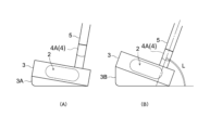
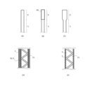
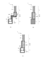
- ⁇ Adapter> 25(A) and (B) are side views for explaining yet another modified example of the above-mentioned golf club 1.
- a golf club 1 having a crank-shaped hosel 4A (hosel A) as shown in Fig. 1(A) is given as an example, but the shape of the hosel 4 is not limited thereto.
- One of a plurality of adapters 3A, 3B is detachably attached to the underside of the head 3 of the golf club 1.
- a plurality of types of these adapters 3A, 3B are prepared, which differ, for example, in shape, mass, center of gravity, etc.
- the adapter 3A shown in Fig. 25(B) is used when it is desired to increase the lie angle L more than the adapter 3B shown in Fig. 25(A).
- the adapters 3A and 3B are preferably attached to the underside of the head 3 via an easily detachable locking structure (clip) or fastening structure (screw).
- clip easily detachable locking structure
- screw fastening structure
- the golf club 1 of this invention comprises a head 3, a shaft 5, a hosel 4, and a grip 6.
- the head 3 has a striking surface 2 for striking a golf ball.
- the shaft 5 is formed in an axial shape.
- the grip 6 is provided at the other end of the shaft 5 and is held by a user.
- the shaft 5 has a hollow shaft cavity 9 (first cavity) therein, the grip 6 has a hollow grip cavity 10 (second cavity) therein communicating with the shaft cavity 9 (first cavity), and a vibration transmission member 20 is built into the shaft cavity 9 (first cavity) and the grip cavity 10 (second cavity).
- the vibration transmission member 20 is formed in an elongated shape, one end of which is fixed to the hosel 4, and the other end of which is fixed to a grip inner plate 23 and a grip inner fixing device 24 (mounting member) provided inside the grip cavity 10 (second cavity).
- the vibration transmission member 20 transmits vibrations generated on the striking surface 2 to the grip 6.
- the vibrations generated on the striking surface 2 of the head 3 can be efficiently transmitted to the grip 6 without attenuation, improving the feel on impact.
- the shaft cavity 9 and the grip cavity 10 can reverberate the vibrations, making the sound heard by the user louder. This further improves the feel and sound on impact.
- the hosel 4 of the present invention is configured of a solid material having a rectangular flat plate shape and a solid cross section, as shown in Fig. 1(B), for example, by extending a planar flat hosel 4B (hosel 4) of a certain thickness parallel to the striking surface 2, the vibration of the striking surface 2 is converted into a planar vibration (membrane vibration) of the hosel 4. This allows the vibration to be efficiently transmitted to the vibration transmitting member 20, allowing the user to feel the vibration accurately and delicately.
- the hosel 4 of the present invention is made of a solid material having two bent portions in the middle and a solid cross section, as shown in Fig.
- the vibrations of the striking surface 2 are transmitted to the vibration transmission member 20 via the crank-shaped hosel 4A (hosel 4). Therefore, the crank shape improves the vibration transmission efficiency, while the vibrations generated on the striking surface 2 of the head 3 can be efficiently transmitted to the grip 6 without attenuation, improving the feel on impact.
- the hosel 4 of the present invention may have a hosel cavity 8 (third cavity) formed therein, which is hollow.
- a hosel cavity 8 third cavity formed therein, which is hollow.
- sound can be generated in the hosel cavity 8. This allows the user to confirm the vibration of the striking surface 2 as sound, further improving the feel on impact.
- the hosel 4 may be in a crank shape having two bent portions in the middle, or in a rectangular flat plate shape.
- the attachment member (rack 41, pinion 42, motor 43, and winding device 44 in the figure) that connects the other end of the vibration transmission member 20 to the grip 6 may be provided so that its position can be adjusted in the extension direction of the grip 6.
- the position to which the vibration of the vibration transmission member 20 is transmitted can be adjusted, and the vibration can be transmitted to the grip 6 efficiently. Therefore, the hitting feel can be further improved.
- the hosel 4 has a built-in vibration sensor 95 that detects vibrations generated on the striking surface 2, which makes it possible to electrically process the vibrations in addition to transmitting them via the vibration transmission member 20.
- the vibrations detected by the vibration sensor 95 can be amplified and output as sound, allowing the user to confirm the vibrations on the striking surface 2 as sound, further improving the feel of the hit.
- the hosel 4 has a built-in vibration device 96 that vibrates based on information detected by a vibration sensor or a speaker 96A that emits sound. This makes it possible to increase the vibration and sound that are actually transmitted to the user, thereby further improving the feel of the hit.
- the vibration and sound can be increased at the user's hand, further improving the hitting feel.
- a mass member 26 that acts as a weight for amplifying vibration may be attached to the vibration transmission member 20, 20' of the present invention.
- the vibration of the vibration transmission member 20 can be easily amplified, or the damping of the vibration can be suppressed, thereby improving the vibration transmission efficiency. Therefore, the hitting feeling can be further improved.
- the hosel 4 of the present invention has a hosel cavity 8 (third cavity) formed therein, for example as shown in Fig.
- an auxiliary vibration transmission member 20Z that transmits vibrations generated on the striking surface 2 to the vibration transmission member 20 may be provided inside the hosel cavity 8 (third cavity) to transmit vibrations generated on the striking surface 2 to the vibration transmission member 20.
- the auxiliary vibration transmission member 20Z allows the vibrations generated on the striking surface 2 to be efficiently transmitted to the vibration transmission member 20 without attenuation, thereby further improving the feel on impact.
- the head 3 of the present invention may have a head cavity 7 (fourth cavity) inside.
- the head cavity 7 can also resonate vibrations, and the sound heard by the user can be amplified. This can further improve the hitting feel.
- a weight member 61 for changing the position of the center of gravity of the head 3 can be applied to the head 3 of the present invention. By changing the attachment position and attachment angle of such a weight member 61, the center of gravity of the head 3 can be easily moved, and a good hitting feel can be provided.
- a weight motor 62 may be provided as a drive source for moving the weight member 61.
- the weight member 61 is provided, for example, inside a hollow cylindrical recess formed in the top surface of the head 3.
- the weight motor 62 also drives and rotates the weight member 61 along the inner peripheral surface of the recess. With this configuration, the center of gravity of the head 3 can be easily adjusted using the weight motor 62. This can further improve the feel of the hit.
- the golf club 1 of the present invention can be equipped with a controller 100 having a rhythm box function and a synthetic voice generating function that notifies the user of the rhythm when hitting the golf ball, as shown in Figures 23 and 24.
- a controller 100 having a rhythm box function and a synthetic voice generating function that notifies the user of the rhythm when hitting the golf ball, as shown in Figures 23 and 24.
- one of the rhythmic sound and the synthetic voice generated by the controller 100 can be output from the speaker 96A, providing assistance in hitting the golf ball to the user of the golf club 1.
- the golf club 1 of this case has one of a number of adapters 3A, 3B removably attached to the underside of the head 3.
- the adapter 3A, 3B suited to the physique and hitting form of the user of the golf club 1, it becomes easier to optimize the swing trajectory of the golf club 1, and it becomes possible to improve the effect of practice.
- the golf club 1 of this embodiment may have a transmitter that transmits signals from the vibration sensor 95 to the outside. This allows information about the vibrations detected by the vibration sensor 95 (vibration data, vibration information) to be used by an external device (such as a smartphone, computer, or data server).
- an external device such as a smartphone, computer, or data server.
- the hosel hollow portion 8 may have openings 80, 80A, 80B that communicate the inside of the hosel hollow portion 8 with the outside.
- the openings 80, 80A, 80B allow the reverberation in the hosel hollow portion 8 to be transmitted to the outside of the hosel 4, so that the sound heard by the user can be amplified, the hitting feel can be further improved, and the hitting sound can be sufficiently confirmed.
- the openings 80, 80A, 80B can be closed with lids 81, 81A, 81B.
- the golf club 1 of this invention may further have openings 90, 92 that connect the internal space of the shaft cavity 9 (first cavity) or the internal space of the grip cavity 10 (second cavity) to the outside, and lids 91, 93 that close the openings 90, 92.
- the openings 90, 92 and the lids 91, 93 form a covered inspection window for the vibration transmission member 20 in the shaft 5 or the grip 6. This allows the condition of the vibration transmission member 20 in the shaft 5 or the grip 6 to be easily inspected.
- the multiple vibration transmission members 20, 20' may be collectively attached to a single mounting member, or each of the multiple vibration transmission members 20, 20' may be individually attached to a corresponding mounting member.
- a plurality of sets of racks 41, pinions 42, motors 43, and winding devices 44 may be provided as a plurality of mounting members corresponding to the plurality of vibration transmission members 20, 20', respectively.
- the positions of the plurality of vibration transmission members 20, 20' can be individually adjusted in the extending direction of the grip 6, and vibrations can be efficiently transmitted to the grip 6. Therefore, the hitting feel can be further improved.
- the other ends of the multiple vibration transmission members 20, 20' are fixed to an upper mounting member 27U (mounting member, grip side plate) provided inside the grip cavity 10 (second cavity), and one end is fixed to a lower mounting member 27D (mounting member, hosel side plate).
- Each of the upper mounting member 27U and the lower mounting member 27D is in the shape of a disk extending along a plane intersecting the extending direction of the vibration transmission members 20, 20', and is provided with multiple connecting holes 28U, 28D that connect the multiple vibration transmission members 20, 20', respectively.
- the multiple vibration transmission members 20, 20' can be attached with a simple configuration.
- vibration transmission members 20 can be applied to any of the golf clubs described above.
- Various shapes of vibration transmission members 20 and various components such as upper mounting member 27U and lower mounting member 27D, fixture 22, grip internal fixture 24, winding device 44, etc. can be freely combined.
- the battery for the smartphone also serves as the battery for the above circuit.
- the golf club 1 can be manufactured using a variety of techniques in addition to or in place of the usual golf club manufacturing techniques.
- the part can be manufactured using a 3D printer, a seamless welding method, a casting method, or an appropriate combination of these methods.
- the practice machine T is provided with a cup area T1 in which a cup C is provided on the golf ball rolling surface, and a hitting area T2 which is provided apart from the cup C, has a golf ball rolling surface, and is a hitting position for a user.
- the practice machine T is, for example, a practice green, and in this case, the cup C is recessed into the golf ball rolling surface of the cup area T1.
- the practice machine T is a golf practice mat.
- the cup C is not recessed, but is provided as a predetermined area (flat surface) on the golf ball rolling surface.
- the cup C may be formed as a shallow recessed portion on the mat.
- the cup C is not limited to a hole, and may be any target position for cupping in a golf ball.
- the training machine T is a facility for a user (golfer) standing in a hitting area T2 to practice putting by hitting a ball B toward a cup C provided in a cup area T1 with a golf club 1'.
- the golf ball rolling surface is the surface on which the hit ball B rolls, and is the floor surface of the cup area T1 and the hitting area T2.
- the directions used to explain the golf practice system S are defined as follows. Using the user putting in the hitting area T2 as a reference, the direction from the user toward the cup C is “front” (marked “F” in the figure), and the opposite side of "front” is “back” (marked “B” in the figure), with “left” and “right” (marked “L” and “R” in the figure) defined based on “front.” In addition, “up” and “down” (marked “U” and “D” in the figure) are defined based on the direction in which gravity acts.
- the cup C provided in the cup area T1 of the training machine T is positioned forward of the hitting area T2.
- a pin P made of a rod-shaped member is erected on the cup C.
- the pin P functions as a marker for the cup C to the user in the hitting area T2.
- the system S also includes a control unit 300 that manages the system S, and a terminal device 400 owned by the user.
- the devices 200 to 700 in the system S are connected to each other via a wireless communication network so that they can send and receive data, and can work in conjunction with each other.
- the wireless communication network is a network that complies with well-known wireless communication standards such as Wi-Fi and Bluetooth (registered trademark).
- the outline of this system S is that the control unit 300 generates guide information for providing guidance to the user's golf play based on monitor information acquired by the units 200, 500, 600 and 700, the control unit 300 transmits the guide information to the terminal device 400 etc., and the terminal device 400 etc. provides guidance based on the guide information in advance (in advance) before the user hits the ball, for example.
- the devices 200 to 700 work together via a network to provide interactive guidance for the user's golf practice.
- the guide is advice to the user regarding golf play, model plays, etc. Specifically, examples of advice and model plays include hitting form, swing rhythm of the golf club, ball launch direction, timing, etc.
- the monitor information acquired by the units 200, 500, 600, and 700 in the present system S is a measurement result related to the user's golf play.
- the monitor information includes a plurality of video data, cup-in information, ball hitting information, golf club head angle, and the like.
- the cup unit 200 , the pin unit 500 , the club unit 700 and the photographing unit 600 are monitor information sources that provide monitor information to the control unit 300 .
- the cup unit 200 is built into (attached to) the cup C, and is a mechanism provided for providing monitor information in the cup C to the control unit 300 .
- the cup unit 200 includes a first control device (referred to as the "control device” in the figure) 201, a first sensor (first detection means, referred to as the “sensor” in the figure) 202, and a first communication device (first transmitting device, referred to as the "communication device” in the figure) 203.
- the first control device 201 is an electrical control device including a processor that controls the cup unit 200, a storage device, and the like.
- a first sensor 202 and a first communication device 203 are connected to the first control device 201 so as to be capable of transmitting and receiving data.
- the first sensor 202 is a detection means provided for detecting cup-in information indicating that the golf ball B has been cupped into the cup C.
- the first sensor 202 may be, for example, an impact sensor that detects the impact of a golf ball B falling into a cup C.
- the cup unit 200 includes additional devices such as a camera 205 for photographing the surroundings of the cup C, an audio device 206 including an amplifier, a speaker, and a microphone, a lighting device 207, a laser irradiator 208, and a power source (not shown) for supplying power.
- a camera 205 for photographing the surroundings of the cup C
- an audio device 206 including an amplifier, a speaker, and a microphone
- a lighting device 207 including an amplifier, a speaker, and a microphone
- a lighting device 207 including an amplifier, a speaker, and a microphone
- a lighting device 207 including an amplifier, a speaker, and a microphone
- a lighting device 207 including an amplifier, a speaker, and a microphone
- a lighting device 207 including an amplifier, a speaker, and a microphone
- a lighting device 207 including an amplifier, a speaker, and a microphone
- a lighting device 207 including an amplifier, a speaker, and a microphone
- the pin unit 500 is attached to the pin P, and is a mechanism provided to provide monitor information about the periphery of the pin P to the control unit 300.
- the pin unit 500 includes a second control device (referred to as a "control device” in the figure) 501, a first camera (first photographing means, referred to as a “camera” in the figure) 502, a second communication device (second transmitting device, referred to as a “communication device” in the figure) 503, a first illuminator (referred to as a "laser” in the figure) 504, and a second photoreceiver (referred to as a "photoreceiver” in the figure) 505.
- the second control device 501 is an electrical control device including a processor for controlling the pin unit 500, a storage device, and the like.
- a first camera 502, a second communication device 503, a first illuminator 504, and a second light receiver 505 are connected to the second control device 501 so as to be capable of transmitting and receiving data.
- the first camera 502 is an image sensor provided to capture an image (first image data) of the area around the pin P.
- the first camera 502 is an imaging means that captures an image at least from the pin P toward the hitting area T2.
- the first camera 502 may be configured as a "360-degree camera" that can capture images in all directions, 360° in the vertical and horizontal directions, centered on the pin P.
- the first camera 502 is not limited to a 360-degree camera, and may be a camera that captures an area narrower than 360 degrees.
- the first camera 502 may also be configured as a 3D camera.
- the second communication device 503 is a wireless communication device connected to the control unit 300 (external) via a wireless communication network. Through the second communication device 503, the image data captured by the first camera 502 can be transmitted to the control unit 300 (external) and information can be received from the external.
- the first irradiator 504 is a light source that irradiates a guide laser light that shows a straight line from the pin P toward the hitting area T2. The straight line indicates the rolling trajectory of the ball B.
- the trajectory of the laser light functions as a guide line that indicates the trajectory of the ball B.
- the trajectory of the ball B is the trajectory that connects the cup C to a predetermined hitting position.
- the second light receiver 505 is a light receiving element (sensing device) for receiving (detecting) the guide laser light (guide sub-laser light) from a second irradiator 705 provided in the club unit 700 described later.
- a speed sensor for example, a speed sensor, an acceleration sensor, a gyro sensor, a magnetic sensor, a biometric authentication sensor, an air pressure sensor (pressure sensor), a temperature sensor, a microphone (sound pressure sensor), a direction sensor, a proximity sensor, a brightness sensor (ambient light sensor), a human sensor, an anemometer, a wind vane, an infrared sensor, an infrared camera, a snow accumulation meter (such as a snow accumulation meter based on laser reflection or an image captured by a camera), etc.
- a speed sensor for example, a speed sensor, an acceleration sensor, a gyro sensor, a magnetic sensor, a biometric authentication sensor, an air pressure sensor (pressure sensor), a temperature sensor, a microphone (sound pressure sensor), a direction sensor, a proximity sensor, a brightness sensor (ambient light sensor), a human sensor, an anemometer, a wind vane, an infrared sensor, an infrared camera, a snow
- the light-emitting function (lighting device 507) attached to the pin unit 500 can be used to enhance the identification of the pin P (i.e., the pin P is provided with a lighthouse function).
- the lighting by the lighting device 507 attached to the pin P provides, for example, illumination, neon, lights, spotlights, rotating spotlights, mirror balls, LED lighting, etc., around the pin P.
- the lighting device 507 attached to the pin P turns on when, for example, a human sensor included in the sensor 508 of the pin unit 500 detects a person approaching the pin P. Such a lighting function can be switched on and off.
- the third control device 701 is an electrical control device including a processor for controlling the club unit 700, a storage device, and the like. Each of the elements 702 to 710 is connected to a third control device 701 so as to be able to transmit and receive data.
- the second camera 702 is an image sensor provided to capture an image (second image data) of the surroundings of the golf club 1'. In this embodiment, the second camera 702 is an image capture means for capturing an image at least from the head of the club 1' toward the front.
- the second sensor 704 is a detection means for detecting impact information related to the impact of the golf ball as one of the monitor information.
- the second sensor 704 is, for example, an impact sensor for detecting impact data when the golf ball is hit with the striking surface, and an angle sensor for detecting the angle of the head when hitting the golf ball, and is built into the head 3 (FIG. 1(A) etc.).
- the vibration sensor 710 is a detection means for detecting vibration information related to the vibration of the vibration transmission members 20, 20' (FIG. 5(A) etc.) provided on the golf club 1' as one of the monitor information.
- the vibration sensor 710 is built into the hosel 4, for example (see reference numeral 95 in FIG. 23).
- the vibration sensor 710 may be built into the shaft 5 or the grip 6.
- the second irradiator 705 is a light source that irradiates a guide laser beam forward from the head of the golf club 1'.
- the trajectory of the laser beam functions as a guide line that indicates the trajectory of the ball B.
- the trajectory of the ball B is a trajectory that is substantially perpendicular to the striking surface of the head and extends linearly forward from the striking surface.
- the display device 706 is a display device that displays visual information.
- An example of the display device 706 is an LCD.
- the audio device 707 is an audio input/output device that includes an amplifier, a speaker, and a microphone and reproduces audio signals and inputs voice.
- the first light receiver 708 is a light receiving element (sensing device) for receiving (detecting) the guide laser light from the first irradiator 504 provided in the pin unit 500 .
- the third communication device 703 is a wireless communication device connected to the control unit 300 (external) via a wireless communication network. Via the third communication device 703, it is possible to transmit video data captured by the second camera 702 and detection signals from the second sensor 704 to the control unit 300 (external) and to receive information from the external.
- the club unit 700 is provided with a lighting device 709, a power source for supplying electric power (not shown), and an automatic operation mechanism for automatically operating various adjustments related to shooting by the second camera 702 (for example, focusing, brightness adjustment, tracking of a subject to be shot, switching of shooting direction, etc.), which are detachable from the club unit 700 or integral with the club unit 700.
- sensors for example, a speed sensor, an acceleration sensor, a gyro sensor, a magnetic sensor, a biometric authentication sensor, an air pressure sensor (pressure sensor), a temperature sensor, a microphone (sound pressure sensor), a direction sensor, a proximity sensor, a brightness sensor (ambient light sensor), a human sensor, an anemometer, a wind vane, an infrared sensor, an infrared camera, a snow accumulation meter (such as a snow accumulation meter based on laser reflection or an image captured by a camera), etc.
- a speed sensor for example, a speed sensor, an acceleration sensor, a gyro sensor, a magnetic sensor, a biometric authentication sensor, an air pressure sensor (pressure sensor), a temperature sensor, a microphone (sound pressure sensor), a direction sensor, a proximity sensor, a brightness sensor (ambient light sensor), a human sensor, an anemometer, a wind vane, an infrared sensor, an infrared camera, a snow accumulation meter
- the golf club 1' can be configured as an "AI club” having multiple functions, such as automatically taking pictures of the surroundings, detecting hitting information, emitting laser light, outputting sound, operating by voice command input, and emitting light.
- the lighting by the lighting device 709 attached to the golf club 1' provides, for example, lighting, illumination, neon, lights, spotlights, rotating spotlights, mirror balls, LED lighting, etc., around the golf club 1'.
- the lighting device 709 attached to the golf club 1' turns on, for example, when a human sensor mounted on the golf club 1' detects a person approaching the golf club 1'. Such a lighting function can be switched on and off.
- the photographing unit 600 is attached to the hitting area T2 of the golf training machine, and is a mechanism provided to photograph images of the user standing in the hitting area T2 and the user's surroundings, and provide the image data as monitor information to the control unit 300 and equipment within the system S, including the terminal device 400.
- 26 includes a plurality of cameras 602.
- the plurality of cameras 602 includes a left camera 602L (one of the third imaging means) and a right camera 602R (one of the third imaging means) provided on both the left and right sides of the striking area T2, a rear camera 602B (one of the third imaging means) provided behind the striking area T2, and a head-mounted head camera 602H (fourth imaging means) worn on the user's head.
- the control unit 300 is a computer that controls the system S.
- the control unit 300 is installed at an arbitrary location, such as near the training aircraft T or at a system base remote from the training aircraft T.
- the control unit 300 includes a control device 301, a receiving device (first receiving device, referred to as “receiving device” in the figure) 302, a first transmitting device (fourth transmitting device, referred to as “transmitting device” in the figure) 303, and a storage device 304.
- the receiving device 302 and the transmitting device 303 are devices for transmitting and receiving data to and from the outside via a wireless communication network.
- the control unit 300 receives, via the receiving device 302, various types of video data and sensor detection data acquired by the units 200, 500, 600, and 700 in the system S as monitor information.
- the control device 301 is a device that generates predetermined guide information based on the above-mentioned monitor information, and is, for example, a processor that implements a software program for generating guide information.
- the guide information is information for providing the user with guidance on the above-mentioned golf play.
- the transmitting device 303 transmits the guide information generated by the control device 301 to the terminal device 400 .
- the transmitting device 303 may transmit guide information to at least one of the cup unit 200, the pin unit 500, the club unit 700 and the photographing unit 600 (i.e., any device within the system S) in addition to or instead of the terminal device 400.
- the various functions of the control unit 300, including the guide information generation process in the control device 301, may be provided by cloud computing using computing services on a cloud environment (Internet environment).
- the display 402 is an example of a display device that displays (presents) a guide based on the guide information to the user using some kind of visual image, such as a moving image or a still image.
- An example of the display 402 is an LCD.
- the input device 404 is, for example, a touch panel sensor or a button switch.
- Examples of presentation devices other than the display device 402 include an audio device 405 that outputs sound, a light-emitting lighting device (not shown), and a vibration generating mechanism (not shown) that generates vibrations.
- an audio device is used as the guide presenter
- the guide for golf play is presented by, for example, music, voice, electronic sound, sound effect, or some other sound.
- a lighting device is used as the guide presenter
- the guide display or support content is presented by blinking light or changing the light color.
- the guide for golf play is presented by vibration.
- the terminal device 400 may have various built-in sensors.
- sensors include a gyro sensor, a magnetic sensor, a GPS, a biometric authentication sensor, a radar sensor, an air pressure sensor (pressure sensor), a temperature and humidity sensor, a microphone (sound pressure sensor), a direction sensor, a proximity sensor, a brightness sensor (ambient light sensor), an image sensor (camera 406), a vital sensor, a pulse sensor, a body temperature sensor, a moisture sensor, a blood pressure sensor, a distance sensor, a tilt sensor, a topographical sensor, a human presence sensor, an anemometer, a wind vane, an infrared sensor, an infrared camera, a snow depth gauge (such as a snow depth gauge based on laser reflection or an image captured by a camera), etc.
- sensors include a gyro sensor, a magnetic sensor, a GPS, a biometric authentication sensor, a radar sensor, an air pressure sensor (pressure sensor), a temperature and humidity sensor, a
- control device 301 constantly receives, as monitor information, video data acquired from the camera 205 of the cup unit 200, the first camera 502 of the pin unit 500, the cameras 602L, 602R, 602B, 602H of the photographing unit 600, and the second camera 702 of the club unit 700, cup-in information from the first sensor 202 of the cup unit 200, impact information from the impact sensor included in the second sensor 704 of the club unit 700, angle data from the angle sensor, and vibration information from the vibration sensor 710 of the club unit 700.
- the control device 301 stores the received video data, cup-in information, impact information, angle data, and vibration information (monitor information) in a storage device and accumulates them as big data, and generates guide information based on this monitor information to provide guidance to the user on their golf play.
- the control device 301 analyzes the acquired video data using a known image analysis technique to calculate play situation estimation data.
- the play situation estimation data is data estimated from the video of the current play situation.
- the estimated data includes, for example, the user's current position, the user's posture before the swing, head-up analysis, head-up check, the user's line of sight, head position, stance, distance to the pin P, and the like.
- the play situation estimation data allows the control unit 300 to grasp (estimate) the play situation based on the monitor information.
- the control device 301 generates guide information based on the calculated play situation estimation data and the sample (model play) data.
- the guide information is advice (guide) for achieving a better hit based on the current play situation (the user's current position, the user's posture before swinging, head-up analysis, head-up check, the user's line of sight, head position, stance, distance to the pin P, etc.).
- tips for playing golf such as a sample swing trajectory, a sample form, swing rhythm, ball launch direction, standing position, foot width, accurate impact, etc., are presented in the form of pictures, photographs, videos, sounds, rhythmic sounds, characters, etc.
- the playing form of a master or expert such as a professional golf player, can be presented as an example play.
- the storage device 304 is assumed to have stored in advance model data that serves as a reference for guiding golf play, as well as various video, image, and audio data for generating guide information.
- Model data includes, for example, models of the user's posture before a swing, the user's line of sight, head position, stance, body movement, and golf club trajectory.
- the guide content is at least one of a guide video and a guide audio.
- the guide video may include the user's eye position during the swing, head position, posture, head-up analysis, head-up check, hitting form, golf club stroke trajectory, head angle, ball launch angle, head speed, strike strength, swing tempo, glove path (trajectory), and putter face direction (angle).
- the guide voice may be a metronome sound (including music, voice, and other rhythmic sounds) that guides the swing rhythm of the golf club, advice (voice comments) for improving golf play, etc.
- the device may be connected to an interactive online golf lesson service via the Internet.
- a predicted outcome from the current playing situation may be presented.
- Examples of predicted outcomes from the current playing situation include a predicted ball trajectory, a predicted swing trajectory, a predicted form, etc.
- the control device 301 can take into account monitor information accumulated as big data, driving range information regarding the gradient of the green G, grass grain, etc., and personal information regarding the user's age, sex, physique, constitution, height, weight, golfing skills, etc. Taking into account various information can improve the accuracy of the golf play guide provided by the guide information. Also, by adding the user's golf play information history to the guide information, the user's "habits" can be more easily reflected, making it possible to provide personalized golf play guides.
- the control device 301 may also have a function (generation AI) that learns from various collected and accumulated data and automatically generates guide information.
- generation AI generation AI
- a laser beam (guide laser beam) is irradiated from the first illuminator 504 of the pin unit 500 toward the hitting area T2.
- a first light receiver 708 is provided in the club unit 700 of the golf club 1' used by the user of the hitting area T2. Therefore, when the user stands at an appropriate position with respect to the pin unit 500, the first light receiver 708 of the club unit 700 receives the laser beam from the first illuminator 504.
- the display in the system S displays the same. Examples of the display include the display 402 of the terminal device 400 and the display device 706 of the club unit 700.
- the display may be audibly output from a speaker in the system S.
- the speakers in the system S include an audio device 405 in the terminal device 400, an audio device 206 in the cup C, an audio device 506 in the pin P, an audio device 707 in the club unit 700, and the like.
- a laser light (guide sub-laser light) is emitted from the second illuminator 705 of the club unit 700.
- the laser light from the second illuminator 705 is emitted toward the pin P (pin unit 500).
- the pin unit 500 is provided with a second receiver 505. Therefore, when the user stands in an appropriate position relative to the pin unit 500, the second receiver 505 of the pin unit 500 receives the laser light from the second illuminator 705 of the club unit 700.
- the display in the system S displays this fact.
- Examples of the display include the display 402 of the terminal device 400 and the display device 706 of the club unit 700.
- the second receiver 505 receives the guide sub-laser light
- a notification to that effect may be given by audio output from a speaker in the system S.
- Speakers in the system S include the audio device 405 of the terminal device 400, the audio device 206 of the cup C, the audio device 506 of the pin P, and the audio device 707 of the club unit 700.
- the display in the system S displays that fact
- the display in the system S displays that fact
- the display in the system S displays that fact, so that the user can confirm by the display that he or she is standing in an appropriate position with respect to the pin unit 500.
- the content of the display may be anything as long as it notifies the user that he or she is standing in an appropriate position with respect to the pin unit 500.
- the trajectories of the laser light from the first light receiver 708 and the laser light from the second light receiver 505 function as guide lines showing the trajectory of the ball B, so that the user can understand the direction in which the ball B is to be hit while standing at an appropriate position relative to the pin unit 500.
- a visual guide regarding putting (hitting the ball B) can be provided to the user.
- the bidirectional guide light can provide more reliable guidance.
- the irradiation angle between the first illuminator 504 of the pin unit 500 and the second illuminator 705 of the club unit 700 can be automatically adjusted based on the results of analysis of the above monitor information and video data. This allows for accurate guidance that reflects the current playing situation by adjusting the direction of the laser light.
- control device 301 can provide feedback on the play result after the hit is completed based on the results of analyzing the video data.
- the control device 301 identifies the swing made by the user in the video based on the result of analyzing the video data, analyzes the identified swing, and tracks the hit golf ball B in the video to analyze the movement of the golf ball B.
- analyzing and evaluating the swing includes analyzing the user's form and analyzing the movement of the golf club (head).
- analysis items for the user's form include the user's eye position, head position, posture, head-up analysis, and head-up check.
- analysis items for golf club (head) movement include the golf club stroke trajectory, head angle, head speed, impact strength, putter face angle, ball launch angle, club path (in-out/out-in movement of the club head at impact), swing tempo, swing flow, and club head flow.
- Examples of analysis items for the movement of the golf ball B include the speed of the golf ball B, the launch angle (launch direction) of the golf ball B, and the flight distance of the golf ball B.
- the control device 301 calculates analysis result data for each of the above items by analyzing the video data, and generates the calculated various analysis result data as practice support information.
- the analysis result data generated as support information is used as information for displaying the analysis results and evaluation of the golf play for each of the above items.
- the control device 301 transmits the analysis result data generated as support information to the terminal device 400.
- the fourth control device 401 of the terminal device 400 displays the analysis results and evaluation of the golf play for each of the above items on the display 402 as practice support content based on the received analysis result data (support information). In other words, feedback on the golf play results is provided. Such feedback contributes to improving the user's golfing technique. Furthermore, visualizing one's own play as numerical values and images also contributes to improving the enjoyment of golf.
- Examples of analysis results of golf play displayed as support content on the display 402 are listed below. That is, examples of support content include the speed of golf ball B, launch angle (launch direction) of golf ball B, flight distance of golf ball B, number of rotations of ball B, rotation direction of ball B, rotation speed, ball quality, quality of rotation, video recording the user's form during a swing, continuous photos recording the user's form during a swing using high-speed photography, the user's line of sight during a swing, head position, posture, head-up analysis, head-up check, golf club stroke trajectory, measured head angle, measured head speed, measured impact strength, swing tempo, swing flow, and club head flow.
- the golf club stroke trajectory includes the so-called grab pass.
- the head angle includes the direction (angle) of the putter face.
- the feedback on the golf play result is not limited to the above-mentioned visual feedback, but may be provided by audio information (i.e., auditory feedback).
- the auditory feedback is to transmit the analysis result of the golf play by voice.
- the audio feedback may be "nice shot”, “off”, “hooked”, “open”, “off by n degrees (n is any number)", “hooked by n degrees (n is any number)", “open by n degrees (n is any number)", etc., in response to the swing made by the user.
- audio feedbacks can be provided in combination with the above visual feedback.
- the storage device 304 of the control unit 300 is provided with a database that stores various voice data (audio data) to be used for auditory feedback.
- the control device 301 extracts voice data to be provided to the user from the database based on the various analysis result data calculated, and generates practice support information including this voice data.
- the terminal device 400 outputs a sound based on the transmitted audio data. For example, headphones or earphones can be used to output the sound. Note that the sound output may be performed not only by the terminal device 400 but also by an audio device of any device in the system S.
- the control device 301 may generate banner advertisement display information and transmit it to the terminal device 400 of the user in conjunction with providing the above-mentioned guide information and feedback on the golf play results.
- the banner advertisement display information is information for displaying a banner advertisement video (a small advertisement displayed in a part of the screen).
- the terminal device 400 displays the banner advertisement in association with the provision of guide information or feedback on the golf play result.
- the banner advertisement may be displayed on any display device within the system S in addition to the terminal device 400 .
- the control device 301 may generate advertising audio output information instead of or in addition to the banner advertising display information, and transmit the generated advertising audio output information to the terminal device 400 of the user.
- the terminal device 400 outputs the advertising audio in association with the feedback on the golf play result.
- the content of the output video and audio is not limited to advertisements and may be any video or audio (for example, ASMR, etc.).
- control unit 300 contents provided from the control unit 300 to the terminal device 400 and other devices 200, 500, 700 in this system S are not limited to those described above.
- audio and video guidance for "prize presentation,” advertising videos and audio, points awarded at stores and websites, miles, mileage, stay mileage, discount tickets, service coupons, music, support audio, lighting effects, etc. may be provided.
- the storage device 304 of the control unit 300 is provided with a database that stores a large amount of information (including advertising video signals) related to advertising videos, advertising audio, points awarded at stores and websites, music, support audio, lighting effects, etc.
- the control unit 300 extracts information related to advertising videos, advertising audio, points awarded at stores and websites, miles, mileage, stay mileage, discount tickets, service coupons, music, support audio, lighting effects, etc. from the database in response to, for example, a cup-in, and transmits it to the terminal device 400.
- the support audio is audio that enhances the enjoyment of playing golf, specifically, cheers, cheers, applause, etc. from the gallery.
- the lighting effects are effects that enhance the enjoyment of the user during golf by controlling the on/off, color, brightness, etc.
- the lighting provides illumination, neon, lights, spotlights, rotating spotlights, mirror balls, LED lighting, etc.
- the lighting effects may be accompanied by music playback.
- the user can select the desired music genre and song, such as disco, gravure music, classical music, pop music, enka, etc.
- the control of the light source device can be changed according to the selected music genre.
- the timing for providing banner advertisement images, advertisement audio, music, etc. is not limited to when the ball goes in. Advertisement images, advertisement audio, music, radio broadcasts, movies, etc. can be provided at any timing during practice with the practice machine T.
- Providing "music" as described above includes playing music based on a playlist of desired music genres or desired songs created by the user, and playing music selected by a DJ (disc jockey). The user may be able to request a desired song in relation to the DJ's selection. The music provided may also be so-called "karaoke.” In this case, the user can sing along with the karaoke performance.
- the user can arbitrarily switch on and off the playback of audio and video such as advertising videos, advertising audio, music, radio broadcasts, movies, television, video distribution services, etc.
- audio and video such as advertising videos, advertising audio, music, radio broadcasts, movies, television, video distribution services, etc.
- the user can individually select, for example, from the terminal device 400, whether or not the various contents described above are provided.
- the terminal device 400 may provide a competitive game function, a putting game, an approach game, and the like, linked to the acquired monitor information.
- the user's terminal device 400 is a wearable device (head-mounted wearable device) that is worn on the head, such as smart glasses or a glasses-type wearable device
- the above-mentioned various guide displays and images of the support content are superimposed on the real world and displayed on the display 402 of the terminal device 400.
- AR Augmented Reality
- VR Virtual Reality
- MR Mated Reality
- the display 402 of the terminal device 400 can be used to play audio and video such as advertising videos and audio, music, radio broadcasts, and movies, browse websites, and view various file documents while playing golf or moving between courses.
- audio and video such as advertising videos and audio, music, radio broadcasts, and movies
- browse websites and view various file documents while playing golf or moving between courses.
- a user can have an auditory and visual experience or perform auditory and visual tasks that are separate from golf.
- the user can appropriately select from the various guide displays and support contents described above on the terminal device 400 and receive support contents in a desired combination.
- the analysis results of the video data and the generated support information may be stored as big data in the storage device of the control device 301 (control unit 300).
- control unit 300 By storing the analysis results of the video data and the generated support information as big data in the control unit 300, a data platform that accumulates golf play information can be provided. Big data can be mutually utilized by multiple golf training machines.
- a display (monitor) 1M for the user is provided in the hitting area T2.
- This monitor 1M is an example of a display device for displaying various information, and is installed near the user.
- the monitor 1M is provided with a control device 901, a display device 902, a communication device 903, an input device 904, an audio device 905, a camera 906, a sensor 907, a lighting device 908, etc.
- a speed sensor for example, a speed sensor, an acceleration sensor, a gyro sensor, a magnetic sensor, a biometric authentication sensor, an air pressure sensor (pressure sensor), a temperature sensor, a microphone (sound pressure sensor), a direction sensor, a proximity sensor, a brightness sensor (ambient light sensor), a human sensor, an anemometer, a wind vane, an infrared sensor, an infrared camera, a snow depth meter (such as a snow depth meter based on laser reflection or an image captured by a camera), etc.
- a speed sensor for example, a speed sensor, an acceleration sensor, a gyro sensor, a magnetic sensor, a biometric authentication sensor, an air pressure sensor (pressure sensor), a temperature sensor, a microphone (sound pressure sensor), a direction sensor, a proximity sensor, a brightness sensor (ambient light sensor), a human sensor, an anemometer, a wind vane, an infrared sensor, an infrared camera, a snow
- the monitor 1M functions as one of the devices in the practice system S, and can be configured as a multi-functional AI device that can link with other devices in the system S, display various information to the user, output audio, and perform specific functions and emit light in response to specific voice input such as "Alexa (registered trademark),” "OK Google (registered trademark),” or "Hey Siri (registered trademark).”
- Monitor 1M may display the various guides mentioned above, support content, video and still images of the user's form, weather, current news, the user's score, ranking, and the like. Monitor 1M allows the user to easily check the visual information provided by system S. Additionally, monitor 1M functions as one element of golf practice system S in conjunction with other devices in system S. For example, a user may use monitor 1M to connect to an interactive online golf lesson service via the Internet.
- an electronic scoreboard 800 may be installed at any location within the golf practice system S (for example, behind the cup area T1).
- the electronic scoreboard 800 is an example of a display for displaying various information within the golf practice system S, and is preferably a large display device, for example, from the viewpoint of ensuring visibility.
- the size of the electronic scoreboard 800 is not particularly limited.
- the electronic scoreboard 800 may be configured as an information terminal device equipped with attached mechanisms such as a control device 801, a display device 802, a communication device 803, an input device 804, an audio device 805, a camera 806, a sensor 807, and a lighting device 808, and can function as one of the devices that make up the system S.
- the sensor 807 may be, for example, a speed sensor, an acceleration sensor, a gyro sensor, a magnetic sensor, a biometric authentication sensor, an air pressure sensor (pressure sensor), a temperature sensor, a microphone (sound pressure sensor), a direction sensor, a proximity sensor, a brightness sensor (ambient light sensor), a human presence sensor, an anemometer, a wind vane, an infrared sensor, an infrared camera, a snow depth meter (such as a snow depth meter based on laser reflection or images captured by a camera), etc.
- a speed sensor for example, a speed sensor, an acceleration sensor, a gyro sensor, a magnetic sensor, a biometric authentication sensor, an air pressure sensor (pressure sensor), a temperature sensor, a microphone (sound pressure sensor), a direction sensor, a proximity sensor, a brightness sensor (ambient light sensor), a human presence sensor, an anemometer, a wind vane, an infrared sensor, an infrared camera
- the electronic bulletin board 800 functions as one of the devices in the practice system S, and can be configured as a multi-functional AI device that works in conjunction with other devices in the practice system S, displays various information to the user, outputs audio, performs a specified function in response to a specified voice input such as "Alexa (registered trademark)", “OK Google (registered trademark)", or "Hey Siri (registered trademark)", and emits light.
- the display of various information on the electronic bulletin board 800 is controlled, for example, by the control unit 300.
- the electronic bulletin board 800 may be controlled not only by the control unit 300, but also by any of the cup unit 200, the control unit 300, the terminal device 400, the pin unit 500, the photographing unit 600, and the club unit 700 in the system S.
- the electronic bulletin board 800 may display the above-mentioned various guide displays and support content. In addition to the above-mentioned guides and content, any information such as weather, current news, user scores, rankings, etc. may be displayed on the electronic bulletin board 800.
- a projector may be provided instead of or in addition to the electronic bulletin board 800. Images can be projected into the system S by projection mapping using the projector.
- any of the cameras provided within the golf practice system S may be configured as a 3D camera.
- each device in the golf practice system S may be configured to share its respective power status (e.g., remaining battery power) and operating status (meters).
- the photographing unit 600 since the photographing unit 600 is arranged to surround the user standing in the hitting area T2, the photographing unit 600 can photograph the whole body (all around) image of the user.
- measurement data can be obtained when custom-making clothing, clothes, accessories, tools, etc., such as golf wear, golf caps, golf shoes, and golf clubs.
- the user can create icons, avatars, and characters (two-dimensional characters, three-dimensional characters) to be used on SNS on the Internet.
- the created avatar can be used in a three-dimensional virtual space constructed on a computer, such as the metaverse.
- the guidance is based on monitor information obtained from multiple monitor information sources (cup unit 200, pin unit 500, club unit 700) arranged at the front (cup C side) and rear (hitting area T2 side) of the training machine T.
- the types of monitor information include multiple types, including video data, hitting information, vibration information, and cup-in information. Therefore, highly accurate guidance that takes into account multiple elements is provided. This can improve the effectiveness of training.
- the monitor information includes vibration information related to the vibration of the vibration transmission member 20, it is possible to provide a guide based on the vibration information.
- various electrical devices may be attached to the hosel 4, such as a pickup that detects vibrations, an amplifier that amplifies vibrations, a speaker that converts vibrations into an audio signal and outputs it, a microphone, an actuator that electrically vibrates the vibration transmission member 20, a communication device, a battery, etc.
- the specific mounting locations of the various electrical devices are not particularly limited, and they may be mounted anywhere on the golf club 1, 1'.
- various electrical devices 4E may be mounted on the upper end 4U of the hosel 4 of the golf club 1.
- the various electrical devices 4E are not limited to this, and may also be provided on the shaft 5 or grip 6.
- a speaker 21S may be built in facing upwards, instead of the grip upper end plate 21 (grip end), at the upper end of the grip 6.
- the sound outlet of the speaker 21S faces upwards, making it easier to transmit sound to the user.
- the upper end of the grip 6 may have an opening 21Z that communicates the grip hollow 10 with the outside, and the inner peripheral shape of the grip hollow 10 including the opening 21Z may be formed into a horn shape that can emphasize (reverberate) the sound.
- the opening 21Z serves as a sound outlet for the ball hitting sound, so that the sound can be easily transmitted to the user.
- the sound from a speaker built into the golf club not shown in FIG.
- the sound collected by a microphone (pickup) may be output from the speaker built into the golf club through the opening 21Z. It can be said that the golf club 1, 1' having a microphone (pickup), a speaker, and the opening 21Z is provided with a loudspeaker function.
- a mesh-like cap 21X as shown in Fig. 28(C), for example.
- the mesh-like cap 21X may be made of any material, such as cloth or plastic.
- a removable cap 21Y may be applied as shown in Fig. 28(D).
- the removable cap 21Y may be attached and detached by any known method such as a screw type or a fitting type.
- the motor 43 and the winding device 44 may be incorporated in a removable cap 21W. With this removable cap 21W, the motor 43 and the winding device 44 can be attached and detached together with the cap 21W, which makes it easier to inspect and maintain the motor 43 and the winding device 44.
- the golf clubs 1 and 1' may have the hosel 4 and the shaft 5 attached detachably, the shaft 5 and the grip 6 attached detachably, or the head 3 and the hosel 4 attached detachably. That is, in the golf clubs 1 and 1', each of the head 3, the hosel 4, the shaft 5, and the grip 6 may be disassembled.
- a tuning fork type sound generating body 20S may be attached to the golf club 1, 1' instead of the vibration transmission member 20.
- the golf club 1, 1' has a head 3, a hosel 4, a shaft 5, and a grip
- the grip 6 is formed integrally with the shaft 5
- the vibration transmission member 20 is built into the shaft cavity 9 in the shaft 5 and the grip cavity 10 in the grip 6, and the lower end of the vibration transmission member 20 is fixed to the hosel 4.
- the tuning fork-type sounding body 20S is a tuning fork-shaped member with an upper portion split into two (U-shape), and is formed as a sounding body that emits sound by vibration.
- the tuning fork-type sounding body 20S has a lower end (one end) fixed to the hosel 4A (hosel 4) via a fastener 22, and is built into the shaft hollow portion 9.
- the tuning fork-type sounding body 20S is set to a dimension shorter than the axial dimension of the shaft 5, and its upper end is not fixed to the shaft 5 or the grip 6.
- the impact and vibration are transmitted to the tuning fork type sounding body 20S via the head 3 and the hosel 4, and the impact and vibration cause the tuning fork type sounding body 20S to vibrate and emit sound. This allows the user to hear the sound associated with the strike. This improves the feel and sound of the strike.
- the golf club 1, 1' shown in FIG. 29(B) is different from the golf club 1, 1' shown in FIG. 29(A) in that the hosel 4A has a hosel cavity 8, but otherwise is the same.
- the tuning fork sounding body 20S is fixed to the inner peripheral surface of the hosel cavity 8 via a fixing device 22.
- the golf club 1, 1' shown in FIG. 29(B) has the same effect as the golf club 1, 1' shown in FIG. 29(A) described above.
- the golf club 1, 1' shown in FIG. 29(C) differs from the golf club 1, 1' shown in FIG. 29(A) in that a string-like vibration transmission member 20, 20' is connected to the upper end of the tuning fork-type sound generating body 20S, and the upper end of the vibration transmission member 20, 20' is attached to a winding device 44, but otherwise is the same.
- the vibration transmission member 20, 20' can transmit vibrations to the grip 6 to improve the feel of the impact, and the winding device 44 can be used to adjust the position to further improve the feel of the impact.
- the golf club 1, 1' shown in Figure 29(D) is different from the golf club 1, 1' shown in Figure 29(B) in that an opening 8X that connects the hosel hollow portion 8 with the outside is provided in the hosel 4, and the tuning-fork-type sounding body 20S can be inserted and removed into the hosel hollow portion 8 and the shaft hollow portion 9 through the opening 8X, but is otherwise common to both.
- the opening 8X can be closed with a lid 8Y. In this case, the opening 8X forms an access port through which the tuning-fork-type sounding body 20S is inserted and removed from the hosel hollow portion 8 and the shaft hollow portion 9.
- the tuning fork-type sounding body 20S being integral with the opening 8X means that the lower end of the tuning fork-type sounding body 20S is attached to the opening 8X via a fixing device 22, and the tuning fork-type sounding body 20S can be attached to and detached from the golf club 1, 1' together with the opening 8X (it is a slip-in type).
- a mechanism may be added to detect the vibration of the tuning fork-type sounding body 20S and amplify it electrically to produce sound.
- a specific example of this mechanism is a structure in which the tuning fork-type sounding body 20S is formed into a net shape by weaving a string-like metal (conductive) material into a net shape, and a pickup coil arranged close to the tuning fork-type sounding body 20S converts the vibration of the tuning fork-type sounding body 20S into an electrical signal, which is then amplified by an amplifier to produce sound. It goes without saying that a golf club equipped with a tuning fork type sounding body 20S may be applied to the golf practice system S shown in FIG.
- the detachable unit 70 can be said to be a housing that houses the vibration transmission member 20 and its fixing device.
- the shape of the main body 70A of the detachable unit 70 is a cylinder that follows the inner peripheral shape of the shaft hollow portion 9 and the grip hollow portion 10, and may be any shape as long as the hollow portion 70B is formed inside.
- the main body 70A has a framework structure that combines multiple vertical beams 70V extending along the axial direction of the shaft 5 and multiple horizontal beams 70H along the axial cross section. Each vertical beam 70V is disposed between the upper end 70U and the lower end 70D at a distance from each other. Each horizontal beam 70H is disposed perpendicular to each vertical beam 70V. Each vertical beam 70V and each horizontal beam 70H form a lattice-like framework structure.
- the detachable unit 71 only needs to be able to accommodate the tuning-fork-type sounding body 20S, and is therefore built into at least the shaft hollow portion 9.
- the detachable unit 70 (FIG. 31(A)) extends from the shaft hollow portion 9 to the grip hollow portion 10 in order to transmit vibrations to the grip 6 via the vibration transmission member 20.
- a golf club fitted with the detachable unit 71 may have a configuration that includes at least the shaft hollow portion 9 inside the shaft 5; in other words, it may or may not have a grip hollow portion 10 inside the grip 6. When a grip cavity 10 is provided inside the grip 6, the detachable unit 71 may extend into the grip cavity 10 as shown by the dashed line in FIG. 31(C).
- the outer peripheral surfaces of the detachable units 70, 71 may or may not be in contact with the inner peripheral surface of the shaft hollow portion 9 (and the grip hollow portion 10). If the outer peripheral surfaces of the detachable units 70, 71 are not in contact with the inner peripheral surface of the shaft hollow portion 9 (and the grip hollow portion 10), for example, a resin ring may be provided on the outer peripheral surface of the detachable units 70, 71 to close the gap with the inner peripheral surface of the shaft hollow portion 9 (and the grip hollow portion 10).
- the detachable units 70 and 71 may incorporate various electrical devices 72 such as a pickup, an amplifier, a speaker, a microphone, an actuator, a communication device, a battery, a motor, and a vibration device (actuator).
- the shape of the grip 6 is not limited to the shapes shown in the drawings, and may be any shape.
- the shaft 5 and the grip 6 may be integrally formed.
- the diameters of the shaft 5 and the grip 6 may be set to be the same, as shown in Fig. 32(A).
- the shaft 5 and the grip 6 have the same diameters, similar to the golf clubs 1 and 1' shown in Fig. 32(A), and the grip 6 is provided with a grip member 6G that covers the periphery of the grip 6.
- the diameter of the grip 6 may be set to be larger than the diameter of the shaft 5. In this case, the grip 6 becomes easier to hold.
- the golf club 1, 1' provided with the grip member 6G may have the head 3, the hosel 4, the shaft 5, and the grip, the grip 6 is formed integrally with the shaft 5, a vibration transmission member 20 is built into the shaft cavity 9 in the shaft 5 and the grip cavity 10 in the grip 6, the lower end of the vibration transmission member 20 is fixed to the hosel 4, and the grip cavity 10 has an attachment member (grip inner plate 23 and grip inner fixing device 24) that connects the upper end of the vibration transmission member 20 to the grip 6 inside.
- the vibration caused by striking the golf ball is transmitted to the grip 6 via the vibration transmission member 20, and the vibration is easily transmitted to the user's hand via the grip member 6G. This can further improve the hitting feeling.
- the material used for the grip 6 may be rubber (natural rubber), elastomer (resin material), fiber reinforced plastic (FRP), ultrafine resin fiber, metal, etc. Note that these materials are merely examples, and the materials used for the grip 6 and the grip member 6G are not limited to these. Note that a golf club equipped with the grip member 6G may of course be applied to the golf practice system S.
- the materials used for each part of the golf club 1, 1' may be any material, such as various metals such as stainless steel, titanium, soft iron, bronze, aluminum, aluminum alloy, aluminum, copper, as well as carbon, plastic, nanocellulose, carbon nanofiber, Japanese paper, leather, polyacetal, PET, glass, aluminum fiber, chemical fiber, resin, polypropylene, nanocellulose, polyester, etc.
- various metals such as stainless steel, titanium, soft iron, bronze, aluminum, aluminum alloy, aluminum, copper, as well as carbon, plastic, nanocellulose, carbon nanofiber, Japanese paper, leather, polyacetal, PET, glass, aluminum fiber, chemical fiber, resin, polypropylene, nanocellulose, polyester, etc.
- 31(A) to 31(E) may have a built-in reinforcing member for strengthening the shaft 5, instead of the vibration transmission member 20 and the tuning-fork-type sounding body 20S.
- a truss-structured reinforcing member 73 is built into the detachable unit 70, 71 shown in FIG. 32(D).
- a reinforcing member for reinforcing the strength of the shaft 5 may be built into the shaft hollow portion 9 of the shaft 5 (detachable unit for reinforcing member).
- a reinforcing member 74 having a truss structure is built into the shaft hollow portion 9 of the shaft 5 shown in Fig. 32(E).
- the golf club to which the detachable units 70, 71 for the reinforcing member 74 are attached may have a configuration without a grip hollow portion 10, that is, a configuration having at least a shaft hollow portion 9 inside the shaft 5.
- the thickness (wall thickness) of the shaft 5 may be thinned to facilitate transmission of vibrations to the hand of the user gripping the grip 6 through the shaft 5.
- the shaft 5 itself functions as a vibration transmission member.
- the shaft 5 may be provided with thick and thin parts, so that the thin parts ensure vibration transmission and the thick parts ensure strength.
- the golf club 1, 1' may be equipped with the various functions listed below.
- the various functions may include an image system, a vital data detection function, a smartphone function, a smartphone function, a communication function, an AI function, a smart speaker function, a display function, a touch panel function, a speech function (conversation function), a GPS function, a beacon function, etc.
- one or more impact sensors 104 can be provided in the head 3, and when a golf ball hits the striking surface 2, the impact data can be detected by the impact sensor 104 and collected by the controller 100, and the impact data can be displayed on the liquid crystal display 102 as numerical values, graphs, etc.
- the changeover switch SW may be used to instruct switching between the two functions, as shown in Fig. 33.
- the switch SW when the switch SW is switched to connect to the liquid crystal display 102, the liquid crystal display 102 displays the hitting direction and impact data that is quantified and graphed, and when the switch SW is switched to connect to the speakers 96A, 96A', the speakers 96A, 96A' output one of the rhythm sounds and the synthetic voice generated by either the rhythm box function or the synthetic voice generating function of the controller 100.
- the switch SW When the switch SW is switched to connect to both the liquid crystal display 102 and the speakers 96A, 96A', the hitting direction and numerically quantified and graphed striking data are displayed on the liquid crystal display 102, and either the rhythmic sound or the synthesized voice is output from the speakers 96A, 96A'.
- the movement of the weight member 61 may be controlled using a smartphone of the user.
- Fig. 34 is a process block diagram for explaining a process configuration for controlling the movement of the weight member 61 using the smartphone of the user.
- the weight motor 62 is connected to the motor control unit 63 so as to be able to transmit and receive data.
- the motor control unit 63 is a computer device (control unit) for controlling the weight motor 62 so that the weight motor 62 moves the weight member 61 .
- the motor control unit 63 is wirelessly connected to the smartphone 65 via the communication unit 64 so as to be able to communicate data with the smartphone 65.
- the smartphone 65 is a portable mobile terminal used by the user to instruct the movement of the weight member 61, and transmits and receives control signals between the smartphone 65 and the motor control unit 63 of the golf club 1.
- the smartphone 65 is provided with a touch input type display 65A.
- the display 65A functions as an input unit for inputting an instruction to move the weight member 61 to a desired position, and also functions as a display unit for displaying on a monitor the position of the weight member 61 that has been moved in response to the movement instruction.
- the wireless connection between the smartphone 65 and the motor control unit 63 may be based on a well-known wireless communication standard such as Bluetooth (registered trademark).
- a connection is established between the smartphone 65 and the motor control unit 63 .
- the motor control unit 63 controls the weight motor 62 to move the weight member 61 to a predetermined initial position, and also supplies the smartphone 65 with current position information of the weight member 61 .
- the user can input an instruction to move the weight member 61 from the smartphone 65 .
- the motor control unit 63 controls the weight motor 62, which moves the weight member 61.
- the smartphone 65 can monitor and display on the display 65A an image showing the position of the weight member 61 that has been moved in response to the movement command, based on the current position information of the weight member 61 supplied from the motor control unit 63.
- the user can check the current position of the weight member 61 on the display 65A of the smartphone 65 and can give a command to move the weight member 61.
- an instruction signal is transmitted from the smartphone 65 to the motor control unit 63.
- the motor control unit 63 controls the weight motor 62 based on the instruction signal to move the weight member 61.
- position information of the weight member 61 is supplied to the smartphone 65 via the motor control unit 63, and the current position of the weight member 61 is updated on the display 65A of the smartphone 65.
- the position of the weight member 61 can be adjusted easily and visually by using the smartphone 65. It goes without saying that such a golf club in which the position of the weight member 61 can be adjusted by using the smartphone 65 may be applied to the golf practice system S shown in FIG.
- pickups 20P, 20ZP that detect these vibrations may be built in.
- the first pickup 20P is a sensor that detects the vibration of the vibration transmission member 20 and converts it into an electrical signal, and is provided in a position close to the vibration transmission member 20.
- the second pickup 20PZ is a sensor that detects the vibration of the auxiliary vibration transmission member 20Z and converts it into an electrical signal, and is provided in a position close to the auxiliary vibration transmission member 20Z.
- These pickups 20P, 20PZ generate electrical signals corresponding to the vibration of the vibration transmission members 20, 20Z, for example, like an electric guitar.
- the golf club 1 shown in FIG. 35(A) comprises a shaft hollow portion 9, a grip hollow portion 10, a vibration transmission member 20, and a first pickup 20P.
- the vibration transmission member 20 is a member that transmits vibrations generated on the striking surface 2 to the grip 6.
- the vibration transmission member 20 is formed in an elongated shape and is provided inside the shaft hollow portion 9 and the grip hollow portion 10.
- the first pickup 20P is provided inside the grip hollow portion 10 and in the vicinity of the vibration transmission member 20.
- a specific example of the vibration transmission member 20 is a wire (for example, a linear member containing a magnetic material such as a steel wire or a piano wire).
- the method of attaching the vibration transmission member 20 is as described in the previous embodiment.
- the golf club 1 includes a hosel cavity 8, a shaft cavity 9, a vibration transmission member 20, an auxiliary vibration transmission member 20Z, and a second pickup 20ZP.
- the golf club 1 shown in FIG. 35(B) may include a grip cavity 10 and a first pickup 20P.
- the auxiliary vibration transmission member 20Z is a member that transmits vibrations generated on the striking surface 2 to the vibration transmission member 20, and is provided inside the hosel cavity 8.
- the second pickup 20ZP is provided in the hosel cavity 8 and in the vicinity of the auxiliary vibration transmission member 20Z.
- auxiliary vibration transmission member 20Z As a specific example of the auxiliary vibration transmission member 20Z, a wire similar to that of the vibration transmission member 20 (for example, a linear member containing a magnetic material such as a steel wire or a piano wire) is used.
- the vibration transmission members 20 and 20Z are attached in the same manner as described in the above embodiment.
- the locations of the first pickup 20P and the second pickup 20ZP are not limited to the above locations, but may be anywhere in the vicinity of the vibration transmission member 20 and the auxiliary vibration transmission member 20Z.
- the electrical signal detected by the first pickup 20P is amplified by an amplifier 90A built into the golf club 1 as shown in FIG. 36 and transmitted to a speaker 90S.
- the electrical signal detected by the second pickup 20ZP may be amplified by the same amplifier 90A and transmitted to the speaker 90S.
- the signal may be amplified by an amplifier 90A' separate from the amplifier 90A, or the amplified electrical signal may be transmitted to a speaker 90S' separate from the speaker 90S.
- the speakers 90S, 90S' output the input electrical signal as sound. As a result, a striking sound is output from the speakers 90S, 90S'. This striking sound can be adjusted by changing the amplification characteristics of the amplifiers 90A, 90A'. If necessary, a filter may be inserted before or after the amplifiers 90A, 90A' to remove noise and unnecessary frequency components from the electrical signal.
- vibrations generated on the striking surface 2 of the head 3 are not only transmitted to the grip 6 via the hosel 4 and shaft 5, but also transmitted to the grip 6 via the vibration transmission member 20.
- the vibrations of the striking surface 2 can be transmitted to the grip 6 efficiently without attenuation. This makes it possible to provide the user with a good hitting feel, and the hitting feel can be improved compared to existing golf clubs.
- the vibrations of the vibration transmission member 20 are detected by the first pickup 20P, converted into an electrical signal, amplified by the amplifier 90A, and output as sound from the speaker 90S. As a result, the hitting sound is output along with the above-mentioned hitting feel, and the synergistic effect provides the user with a good hitting feeling.
- an auxiliary vibration transmission member 20Z is built into the hosel cavity 8.
- the vibrations generated on the striking surface 2 of the head 3 can be efficiently transmitted to the vibration transmission member 20 without attenuation, further improving the hitting feel.
- the vibrations of the auxiliary vibration transmission member 20Z are detected by the second pickup 20ZP, and sounds corresponding to these vibrations are output from the speakers 90S, 90S'. As a result, the hitting sound is output along with the above-mentioned hitting feel, and the synergistic effect provides the user with a good hitting feeling.
- the vibration transmission member 20 and auxiliary vibration transmission member 20Z are provided, the vibrations transmitted through the vibration transmission member 20 and auxiliary vibration transmission member 20Z are detected by the pickups 20P and 20ZP, and the electrical signals resulting from the respective vibrations are amplified by the amplifiers 90A and 90A', appropriately filtered, and emitted as striking sounds from the speakers 90S and 90S'. This provides the user with an even better striking feeling.
- the second auxiliary vibration transmission member 20Z' and the head internal vibration transmission member 3Z are connected via a connecting portion 20K''.
- vibrations generated when a golf ball is struck with the striking surface 2 of the head 3 are transmitted from the in-head vibration transmission member 3Z through the first auxiliary vibration transmission member 20Z and the second auxiliary vibration transmission member to the vibration transmission member 20, and then transmitted to the grip 6 through the vibration transmission member 20. Therefore, a good hitting feel can be provided to the user, and the hitting feel can be improved compared to existing golf clubs.
- vibrations generated when a golf ball is struck with the striking surface 2 of the head 3 are transmitted from the head 3 through the auxiliary vibration transmission member 20Z to the vibration transmission member 20, and then transmitted to the grip 6 through the vibration transmission member 20. Therefore, a good hitting feel can be provided to the user, and the hitting feel can be improved compared to existing golf clubs.
- the golf club 1 shown in Fig. 37(C) is a modified version of the golf club 1 shown in Fig. 37(B), in which the head 3 has a hollow head cavity 7 (fourth cavity) formed therein, and an in-head vibration transmission member 3Z is tensioned in this head cavity 7.
- the lower end of the auxiliary vibration transmission member 20Z is connected to the in-head vibration transmission member 3Z via a connection portion 20K'.
- the vibration transmission member 20 is connected to the upper end of the auxiliary vibration transmission member 20Z via a connection portion 20K.
- the golf club 1, 1' shown in FIG. 38(B) is a modified example of the golf club 1, 1' shown in FIG. 31(C), and is a configuration example in which a removable unit 71 is attached to a golf club that does not have a hosel.
- the golf club 1, 1' shown in FIG. 38(B) has a head 3, a shaft 5, and a grip 6, the shaft 5 has a shaft hollow portion 9 therein, the grip 6 has a grip hollow portion 10 therein, and the main body portion 71A of the removable unit 71 is built into the shaft hollow portion 9.
- a tuning fork type sounding body 20S is provided in the hollow portion 71B of the removable unit 71. That is, the configuration of the golf club 1, 1' shown in FIG.
- ⁇ Winding device> [Appendix 6] The golf club described in Appendix 1, characterized in that the mounting member has a winding device that manually or electrically winds up the other end of the vibration transmission member, and a pinion that meshes with a rack fixed to the inner surface of the second hollow portion and is rotatably attached to the winding device.
- the hosel is provided with a vibration device that vibrates based on information detected by the vibration sensor, and is configured so that vibrations from the vibration device are transmitted to the vibration transmission member.
- a vibration device that vibrates based on information detected by the vibration sensor
- the hosel incorporates another vibration device that vibrates or a speaker that emits sound based on information detected by the vibration sensor.
- ⁇ Types of vibration transmission components [Appendix 10] 2.
- the vibration transmission member is composed of any one of a wire, a string, a rod member, a linear elastic member, and a long coil spring, or any combination of the wire, string, rod member, linear elastic member, and long coil spring.
- the weight member is provided inside a hollow cylindrical recess formed in an upper surface of the head, A drive source that moves the weight member; and a control unit that controls the drive source so that the drive source rotates the weight member along the inner circumferential surface of the recess.
- ⁇ Rhythm box function> [Appendix 18] 2.
- ⁇ Head adapter> [Appendix 19] 2.
- a head having a striking surface for striking a golf ball;
- a shaft formed in an axial shape; a hosel connecting one end of the shaft and the head; a grip provided at the other end of the shaft and held by a user; the hosel is integrally formed with the head and the shaft in a non-replaceable manner;
- the shaft has a first hollow portion formed therein,
- the grip has a second hollow portion formed therein and communicating with the first hollow portion,
- the grip is integrally formed with the shaft;
- a tuning fork-type sound generating body having one end fixed to the hosel, housed in at least the first hollow portion, and vibrating in response to the impact of striking the golf ball with the striking surface to generate sound.
- [Appendix 34] 34 34.
- the golf club according to claim 33 wherein the one end of the tuning fork-type sound generating body is fixed to the hosel via a vibration transmission member.
- a mounting member is provided at the other end of the tuning-fork type sound generating body, the mounting member being provided inside the second hollow portion and connecting the other end to the grip via a vibration transmission member;
- the golf club described in Appendix 33 or 34 characterized in that the mounting member has a winding device that manually or electrically winds up the vibration transmission member, and a pinion that meshes with a rack fixed to the inner surface of the second hollow portion and is rotatably attached to the winding device.
- a head having a striking surface for striking a golf ball, a shaft formed in an axial shape, a hosel connecting one end of the shaft to the head, and a grip provided at the other end of the shaft to be held by a user, the shaft having a first hollow cavity therein, and the grip having a second hollow cavity therein communicating with the first hollow cavity, a main body portion that is incorporated in the first hollow portion and the second hollow portion, extends in the axial direction of the shaft, has a cylindrical shape that conforms to inner circumferential shapes of the first hollow portion and the second hollow portion, and has a hollow portion formed therein;
- a detachment unit for a vibration transmission member characterized in that it comprises a vibration transmission member that is formed in a long shape, has one end fixed to the lower end of the main body, is incorporated in the hollow portion, and transmits vibrations generated on the striking surface to the grip.
- a head having a striking surface for striking a golf ball, a shaft formed in an axial shape, and a grip provided at the other end of the shaft and held by a user, the shaft being detachably attached to a golf club having a first hollow portion formed therein; a main body portion that is incorporated in the first hollow portion, extends in the axial direction of the shaft, has a cylindrical shape that conforms to an inner circumferential shape of the first hollow portion, and has a hollow portion formed therein;
- a detachable unit for a tuning fork-type sounding body comprising: a tuning fork-type sounding body formed in an elongated shape, one end of which is fixed to the lower end of the main body and housed in the hollow portion, and which vibrates in response to the impact of striking the golf ball with the striking surface to produce sound.
- a head having a striking surface for striking a golf ball, a shaft formed in an axial shape, and a grip provided at the other end of the shaft and held by a user, the shaft being detachably attached to a golf club having a first hollow portion formed therein; a main body portion that is incorporated in the first hollow portion, extends in the axial direction of the shaft, has a cylindrical shape that conforms to an inner circumferential shape of the first hollow portion, and has a hollow portion formed therein;
- a reinforcing member attachment/detachment unit comprising: a reinforcing member that is built into the hollow portion and reinforces the strength of the shaft.
- a golf club comprising: a shaft formed in an axial shape; a head provided at one end of the shaft and having a striking surface for striking a golf ball; and a grip provided at the other end of the shaft and held by a user, 1.
- a grip for a golf club comprising: a grip member made of a mesh member formed by molding resin fibers into a net shape; [Appendix 45] 2. The golf club according to claim 1, wherein an electric display member is provided on the upper surface of the head. [Appendix 46] 46.
- the display member is a liquid crystal display capable of displaying at least one piece of information of the launch direction of the golf ball and impact data when the golf ball hits the striking surface in response to an external instruction.
- the vibration transmission member is configured to contain a magnetic material, 2. The golf club according to claim 1, further comprising a first pickup disposed adjacent to the vibration transmission member for detecting vibration transmitted by the vibration transmission member and converting the detected vibration into an electrical signal.
- the auxiliary vibration transmission member is configured to contain a magnetic material, 15. The golf club according to claim 13 or 14, further comprising a second pickup disposed adjacent to the auxiliary vibration transmission member for detecting vibrations transmitted by the auxiliary vibration transmission member and converting the vibrations electrically.
- the weight member is provided inside a linear recess formed in an upper surface of the head, A drive source that moves the weight member; 17.
- the golf club according to claim 16 further comprising: a control unit that controls the drive source so that the drive source slides the weight member along an inner circumferential surface of the recess.
- a portable mobile terminal for transmitting and receiving a control signal to and from the control unit of the golf club according to claim 17 or 49, an input unit for inputting an instruction to move the weight member to a desired position; a display unit that monitors and displays a position of the weight member to which the weight member has been moved in response to the movement instruction from the input unit.
- the head has a fourth cavity formed therein, 14.
- the golf club according to claim 13 further comprising an internal vibration transmission member disposed inside the fourth hollow portion and configured to transmit vibrations generated on the striking surface to the auxiliary vibration transmission member.
- the head has a fourth cavity formed therein, 15.
- the golf club according to claim 14 further comprising an internal vibration transmission member disposed inside the fourth hollow portion and configured to transmit vibrations generated on the striking surface to the auxiliary vibration transmission member.
Landscapes
- Health & Medical Sciences (AREA)
- General Health & Medical Sciences (AREA)
- Physical Education & Sports Medicine (AREA)
- Life Sciences & Earth Sciences (AREA)
- Biophysics (AREA)
- Golf Clubs (AREA)
Abstract
Description
本発明は、ゴルフボールを打撃するためのゴルフクラブ、振動伝達部材の脱着ユニット、音叉型発音体の脱着ユニット、補強部材の脱着ユニット、ゴルフクラブを適用したゴルフ練習システム、ゴルフクラブのグリップ及び携帯移動端末に関する。 The present invention relates to a golf club for hitting a golf ball, a detachable unit for a vibration transmission member, a detachable unit for a tuning fork-type sound generating body, a detachable unit for a reinforcing member, a golf practice system using a golf club, a golf club grip, and a portable mobile terminal.
従来、ウッド,アイアン,ハイブリッド,ユーティリティ,パターなどのゴルフクラブにおいて、グリップが設けられたシャフトとヘッドとをホーゼルで接続したものが知られている。ホーゼルは、例えばシャフトやヘッドに対して着脱可能に固定される。このような構造により、シャフトやヘッドの交換が容易となる(特許文献1,2参照)。
Conventionally, in golf clubs such as woods, irons, hybrids, utilities, and putters, a shaft with a grip is connected to the head by a hosel. The hosel is removably fixed to the shaft or head, for example. This structure makes it easy to replace the shaft or head (see
ホーゼル付きゴルフクラブの場合、ゴルフボールを打撃したときにヘッドで生じる振動は、シャフトを介してグリップを把持する使用者(ゴルファー)の掌へと伝達され、ゴルフクラブの打感の一部として認識される。一方、シャフトとヘッドとの間に介装されるホーゼルは、このような振動の伝達を阻害するように作用しうる。そのため、ホーゼルが形成されたゴルフクラブでは、ホーゼルのないゴルフクラブと比較して、良好な打感が得られにくいという課題がある。なお、打感とは、ゴルフボールの打撃に際して使用者が抱く感触やショット感を意味する。一般的な打感には、物理的な振動だけでなく、打ち心地や節度感や達成感といった感覚的な操作の心地よさ(フィーリング)も含まれる。 In the case of a golf club with a hosel, the vibrations generated in the head when hitting a golf ball are transmitted via the shaft to the palm of the user (golfer) holding the grip, and are recognized as part of the feel of the golf club. On the other hand, the hosel interposed between the shaft and the head can act to inhibit the transmission of such vibrations. Therefore, a golf club with a hosel has the problem that it is difficult to obtain a good feel when hitting compared to a golf club without a hosel. The feel of the hit refers to the feeling or shot that the user has when hitting a golf ball. A typical hit feel includes not only physical vibrations, but also the comfortableness (feeling) of the sensory operation, such as the feel of the hit, the sense of moderation, and the sense of accomplishment.
本件の目的の一つは、上記のような課題に照らして創案されたものであり、打感を改善できるようにしたゴルフクラブ、振動伝達部材の脱着ユニット、音叉型発音体の脱着ユニット、補強部材の脱着ユニット、ゴルフ練習システム、ゴルフクラブのグリップ及び携帯移動端末を提供することである。また、この目的に限らず、後述する「発明を実施するための形態」に示す各構成から導き出される作用効果であって、従来の技術では得られない作用効果を奏することも、本件の他の目的として位置付けることができる。 One of the objectives of this case was devised in light of the above-mentioned problems, and is to provide a golf club, a detachable unit for a vibration transmission member, a detachable unit for a tuning fork-type sounding body, a detachable unit for a reinforcing member, a golf practice system, a golf club grip, and a portable mobile terminal that are capable of improving the feel of the impact. In addition to this objective, another objective of this case is to achieve effects that are derived from the various configurations shown in the "Form for carrying out the invention" described below and that cannot be obtained with conventional technology.
本件は、以下に開示する態様又は適用例として実現できる。開示のゴルフクラブは、上記の課題の少なくとも一部を解決する。
(1)開示のゴルフクラブは、ゴルフボールを打撃する打撃面を有するヘッドと、軸状に形成されるシャフトと、前記シャフトの一端部と前記ヘッドとを接続するホーゼルと、
前記シャフトの他端部に設けられて使用者に把持されるグリップとを備え、前記ホーゼルが、取り替えできない状態で前記ヘッド及び前記シャフトと一体に形成され、前記シャフトが、中空に形成された第一空洞部を内部に有し、前記グリップが、前記第一空洞部と連通する中空に形成された第二空洞部を内部に有し、前記グリップが、前記シャフトと一体に形成され、長尺状に形成されて一端部を前記ホーゼルに固定され、前記第一空洞部及び前記第二空洞部に内蔵されるとともに、前記打撃面で生じる振動を前記グリップに伝達する振動伝達部材と、前記第二空洞部の内部に設けられ、前記振動伝達部材の他端部と前記グリップとを連結する取付部材とを備えている。
The present invention can be realized as the following disclosed aspects or application examples: The disclosed golf club solves at least a part of the above problems.
(1) The disclosed golf club includes a head having a striking surface for striking a golf ball, a shaft formed in an axial shape, a hosel connecting one end of the shaft to the head,
the grip is provided at the other end of the shaft and is held by a user, the hosel is formed integrally with the head and the shaft in a non-replaceable state, the shaft has a first hollow cavity therein, the grip has a second hollow cavity therein that communicates with the first cavity, the grip is formed integrally with the shaft, is formed in an elongated shape, has one end fixed to the hosel, is built into the first cavity and the second cavity, and comprises a vibration transmission member that transmits vibrations generated on the striking surface to the grip, and an attachment member that is provided inside the second cavity and connects the other end of the vibration transmission member to the grip.
(2)また、開示のゴルフクラブは、ゴルフボールを打撃する打撃面を有するヘッドと、軸状に形成されるシャフトと、前記シャフトの一端部と前記ヘッドとを接続するホーゼルと、前記シャフトの他端部に設けられて使用者に把持されるグリップとを備え、前記ホーゼルが、取り替えできない状態で前記ヘッド及び前記シャフトと一体に形成され、前記シャフトが、中空に形成された第一空洞部を内部に有し、前記グリップが、前記第一空洞部と連通する中空に形成された第二空洞部を内部に有し、前記グリップが、前記シャフトと一体に形成され、一端部を前記ホーゼルに固定され、少なくとも前記第一空洞部に内蔵されるとともに、前記打撃面で前記ゴルフボールを打撃した衝撃により振動して、音を発する音叉型発音体とを備えている。 (2) The disclosed golf club includes a head having a striking surface for striking a golf ball, a shaft formed in an axial shape, a hosel connecting one end of the shaft to the head, and a grip attached to the other end of the shaft and held by a user, the hosel being formed integrally with the head and the shaft in an irreplaceable state, the shaft having a first hollow cavity therein, the grip having a second hollow cavity therein communicating with the first cavity, the grip being formed integrally with the shaft, one end of the grip being fixed to the hosel, and being built into at least the first cavity, and including a tuning fork-type sounding body that vibrates in response to the impact of striking the golf ball with the striking surface to produce sound.
(3)また、開示の振動伝達部材の脱着ユニットは、ゴルフボールを打撃する打撃面を有するヘッドと、軸状に形成されるシャフトと、前記シャフトの一端部と前記ヘッドとを接続するホーゼルと、前記シャフトの他端部に設けられて使用者に把持されるグリップとを備えるとともに、前記シャフトが中空に形成された第一空洞部を内部に有し、前記グリップが前記第一空洞部と連通する中空に形成された第二空洞部を内部に有するゴルフクラブに対して、着脱可能に取り付けられ、前記第一空洞部及び第二空洞部に内蔵され、前記シャフトの軸方向に延在するとともに前記第一空洞部及び第二空洞部の内周形状に沿う筒形状をなすとともに、中空に形成された中空部を内部に有する本体部と、長尺状に形成されて一端部を前記本体部の下端に固定され、且つ、前記中空部に内蔵されるとともに、前記打撃面で生じる振動を前記グリップに伝達する振動伝達部材と、を備えている。
(4)開示の振動伝達部材の脱着ユニットは、ゴルフボールを打撃する打撃面を有するヘッドと、軸状に形成されるシャフトと、前記シャフトの他端部に設けられて使用者に把持されるグリップとを備えるとともに、前記シャフトが中空に形成された第一空洞部を内部に有し、前記グリップが前記第一空洞部と連通する中空に形成された第二空洞部を内部に有するゴルフクラブに対して、着脱可能に取り付けられ、前記第一空洞部及び第二空洞部に内蔵され、前記シャフトの軸方向に延在するとともに前記第一空洞部及び第二空洞部の内周形状に沿う筒形状をなすとともに、中空に形成された中空部を内部に有する本体部と、長尺状に形成されて一端部を前記本体部の下端に固定され、且つ、前記中空部に内蔵されるとともに、前記打撃面で生じる振動を前記グリップに伝達する振動伝達部材と、を備えている。
(3) In addition, the disclosed detachable unit of a vibration transmission member includes a head having a striking surface for striking a golf ball, a shaft formed in an axial shape, a hosel connecting one end of the shaft to the head, and a grip provided on the other end of the shaft and held by a user. The detachable unit is detachably attached to a golf club, the shaft having a first hollow cavity therein and the grip having a second hollow cavity therein communicating with the first hollow cavity, the main body being built in the first cavity and the second cavity, extending in the axial direction of the shaft, having a cylindrical shape that follows the inner circumferential shape of the first cavity and the second cavity, and having a hollow portion therein; and a vibration transmission member that is formed in an elongated shape, has one end fixed to a lower end of the main body, is built in the hollow portion, and transmits vibrations generated at the striking surface to the grip.
(4) The disclosed detachable unit of a vibration transmission member includes a head having a striking surface for striking a golf ball, a shaft formed in an axial shape, and a grip provided at the other end of the shaft and held by a user, and is detachably attached to a golf club, the shaft having a first hollow cavity therein and the grip having a second hollow cavity therein communicating with the first hollow cavity, the main body being built into the first hollow cavity and the second hollow cavity, extending in the axial direction of the shaft, having a cylindrical shape that follows the inner circumferential shape of the first hollow cavity and the second hollow cavity, and having a hollow portion therein, and a vibration transmission member that is formed in an elongated shape, has one end fixed to a lower end of the main body, is built into the hollow cavity, and transmits vibrations generated at the striking surface to the grip.
(5)また、開示の音叉型発音体の脱着ユニットは、ゴルフボールを打撃する打撃面を有するヘッドと、軸状に形成されるシャフトと、前記シャフトの一端部と前記ヘッドとを接続するホーゼルと、前記シャフトの他端部に設けられて使用者に把持されるグリップとを備えるとともに、前記シャフトが中空に形成された第一空洞部を内部に有するゴルフクラブに対して、着脱可能に取り付けられ、前記第一空洞部に内蔵され、前記シャフトの軸方向に延在するとともに前記第一空洞部の内周形状に沿う筒形状をなすとともに、中空に形成された中空部を内部に有する本体部と、長尺状に形成されて一端部を前記本体部の下端に固定され、且つ、前記中空部に内蔵されるとともに、前記打撃面で前記ゴルフボールを打撃した衝撃により振動して、音を発する音叉型発音体と、を備えている。
(6)開示の音叉型発音体の脱着ユニットは、ゴルフボールを打撃する打撃面を有するヘッドと、軸状に形成されるシャフトと、前記シャフトの他端部に設けられて使用者に把持されるグリップとを備えるとともに、前記シャフトが中空に形成された第一空洞部を内部に有するゴルフクラブに対して、着脱可能に取り付けられ、前記第一空洞部に内蔵され、前記シャフトの軸方向に延在するとともに前記第一空洞部の内周形状に沿う筒形状をなすとともに、中空に形成された中空部を内部に有する本体部と、長尺状に形成されて一端部を前記本体部の下端に固定され、且つ、前記中空部に内蔵されるとともに、前記打撃面で前記ゴルフボールを打撃した衝撃により振動して、音を発する音叉型発音体と、を備えている。
(5) The removable unit of the disclosed tuning fork-type sounding body includes a head having a striking surface for striking a golf ball, a shaft formed in an axial shape, a hosel connecting one end of the shaft to the head, and a grip provided on the other end of the shaft and held by a user. The shaft is removably attached to a golf club having a first hollow portion formed therein, the main body being built into the first hollow portion, extending in the axial direction of the shaft, having a cylindrical shape that follows the inner circumferential shape of the first hollow portion, and having a hollow portion formed therein; and a tuning fork-type sounding body that is formed in an elongated shape, has one end fixed to a lower end of the main body, is built into the hollow portion, and vibrates due to the impact of striking the golf ball with the striking surface to produce sound.
(6) The removable unit of the disclosed tuning fork-type sounding body comprises a head having a striking surface for striking a golf ball, a shaft formed in an axial shape, and a grip provided at the other end of the shaft and held by a user. The shaft is removably attached to a golf club having a first hollow portion formed therein, the shaft is built into the first hollow portion, the main body extends in the axial direction of the shaft, has a cylindrical shape that follows the inner circumferential shape of the first hollow portion, and has a hollow portion formed therein; and a tuning fork-type sounding body that is formed in an elongated shape, has one end fixed to a lower end of the main body, is built into the hollow portion, and vibrates due to the impact of striking the golf ball with the striking surface to produce sound.
(7)また、開示の補強部材の脱着ユニットは、ゴルフボールを打撃する打撃面を有するヘッドと、軸状に形成されるシャフトと、前記シャフトの一端部と前記ヘッドとを接続するホーゼルと、前記シャフトの他端部に設けられて使用者に把持されるグリップとを備えるとともに、前記シャフトが中空に形成された第一空洞部を内部に有するゴルフクラブに対して、着脱可能に取り付けられ、前記第一空洞部に内蔵され、前記シャフトの軸方向に延在するとともに前記第一空洞部の内周形状に沿う筒形状をなすとともに、中空に形成された中空部を内部に有する本体部と、前記中空部に内蔵され、前記シャフトの強度を補強する補強部材と、を備えている。
(8)開示の補強部材の脱着ユニットは、ゴルフボールを打撃する打撃面を有するヘッドと、軸状に形成されるシャフトと、前記シャフトの他端部に設けられて使用者に把持されるグリップとを備えるとともに、前記シャフトが中空に形成された第一空洞部を内部に有するゴルフクラブに対して、着脱可能に取り付けられ、前記第一空洞部に内蔵され、前記シャフトの軸方向に延在するとともに前記第一空洞部の内周形状に沿う筒形状をなすとともに、中空に形成された中空部を内部に有する本体部と、前記中空部に内蔵され、前記シャフトの強度を補強する補強部材と、を備えている。
(7) The removable unit of the disclosed reinforcing member includes a head having a striking surface for striking a golf ball, a shaft formed in an axial shape, a hosel connecting one end of the shaft to the head, and a grip provided on the other end of the shaft to be held by a user. The shaft is removably attached to a golf club having a first hollow portion formed therein, the main body being incorporated into the first hollow portion, extending in the axial direction of the shaft and having a cylindrical shape that follows the inner shape of the first hollow portion, and having a hollow portion formed therein, and a reinforcing member incorporated into the hollow portion to reinforce the strength of the shaft.
(8) The removable unit of the disclosed reinforcing member comprises a head having a striking surface for striking a golf ball, a shaft formed in an axial shape, and a grip provided on the other end of the shaft and held by a user, and is removably attached to a golf club having a first hollow portion formed therein, the shaft being incorporated into the first hollow portion, a main body portion extending in the axial direction of the shaft and having a cylindrical shape that follows the inner circumferential shape of the first hollow portion, and having a hollow portion formed therein, and a reinforcing member incorporated into the hollow portion to reinforce the strength of the shaft.
(9)開示のゴルフ練習システムは、(1)又は(2)に記載のゴルフクラブによって打撃されたゴルフボールの転動面(ゴルフボール転動面)に設けられたカップと、前記カップから離隔し前記ゴルフボール転動面を有する打撃エリアと、前記カップに対し抜き差し可能に立設されて前記カップの目印となる棒状のピンと、前記ピンに付設され前記ピンから前記打撃エリアに向けてストレートラインを示すガイド用レーザ光を照射する第一照射器と、前記ゴルフクラブに付設され前記第一照射器からの前記ガイド用レーザ光を受光しうる第一受光器と、前記ゴルフクラブに付設され前記ゴルフクラブから前記ピンに向けてガイド用サブレーザ光を照射する第二照射器と、前記ピンに付設され前記第二照射器からの前記ガイド用サブレーザ光を受光しうる第二受光器と、前記第一受光器で前記ガイド用レーザ光を受光するととともに、前記第二受光器で前記ガイド用サブレーザ光を受光すると、その旨を表示する表示器と、を備えている。 (9) The disclosed golf practice system includes a cup provided on the rolling surface (golf ball rolling surface) of a golf ball hit by the golf club described in (1) or (2), a hitting area separated from the cup and having the golf ball rolling surface, a rod-shaped pin that is inserted and removed from the cup and serves as a marker for the cup, a first illuminator attached to the pin and irradiates a guide laser beam showing a straight line from the pin toward the hitting area, a first light receiver attached to the golf club and capable of receiving the guide laser beam from the first illuminator, a second illuminator attached to the golf club and irradiates a guide sub-laser beam from the golf club toward the pin, a second light receiver attached to the pin and capable of receiving the guide sub-laser beam from the second illuminator, and an indicator that receives the guide laser beam with the first light receiver and displays the fact that the guide sub-laser beam is received by the second light receiver.
(10)開示のゴルフ練習システムは、(1)又は(2)に記載のゴルフクラブによって打撃されたゴルフボールの転動面(ゴルフボール転動面)に設けられたカップと、前記カップから離隔し前記ゴルフボール転動面を有する打撃エリアとを有しており、前記打撃エリアに立ったユーザが前記カップに向かって前記ゴルフクラブで前記ゴルフボールを打撃するゴルフ練習機と、前記カップの目印をなす棒状のピンに付設されており、前記ピンから前記打撃エリアに向かって映像を撮影する第一撮影手段と、前記第一撮影手段で撮影された第一映像データを外部に送信する第二送信装置と、前記ピンから前記打撃エリアに向かってガイド用レーザ光を照射する第一照射器と、を有するピンユニットと、前記打撃エリアにおいて前記ユーザが用いる前記ゴルフクラブに付設されており、前記振動伝達部材で伝達される前記振動に関する振動情報を検出する振動検出手段と、前記ヘッドに内蔵され前記ゴルフボールの打撃に関する打撃情報を検出する第二検出手段と、前記ヘッドから前方に向かって映像を撮影する第二撮影手段と、前記ヘッドから前方に向かってガイド用サブレーザ光を照射する第二照射器と、前記振動情報と前記打撃情報と前記第二撮影手段で撮影された第二映像データとを外部へ送信する第三送信装置と、を有するクラブユニットと、前記第一送信装置から送信された前記カップイン情報と前記第二送信装置から送信された前記第一映像データと前記第三送信装置から送信された前記振動情報、前記打撃情報及び前記第二映像データの少なくとも一つをモニタ情報として受信する第一受信装置と、前記モニタ情報に基づき、前記ユーザのゴルフプレイに対するガイドを提供するためのガイド情報を生成する制御装置と、前記ガイド情報を外部に送信する第四送信装置と、を有する制御ユニットと、前記第四送信装置から送信された前記ガイド情報を受信する第二受信装置と、前記ガイド情報に基づきゴルフプレイに対するガイドを提示する提示器と、を有しており、前記ユーザが携帯可能な端末装置と、を備えている。 (10) The disclosed golf practice system includes a golf practice machine having a cup provided on the rolling surface (golf ball rolling surface) of a golf ball hit by the golf club described in (1) or (2), and a hitting area separated from the cup and having the golf ball rolling surface, and a user standing in the hitting area hits the golf ball with the golf club toward the cup, a pin unit having a first photographing means attached to a rod-shaped pin marking the cup and photographing an image from the pin toward the hitting area, a second transmitting device that transmits the first image data photographed by the first photographing means to the outside, and a first illuminator that irradiates a guide laser light from the pin toward the hitting area, a vibration detection means attached to the golf club used by the user in the hitting area and detecting vibration information related to the vibration transmitted by the vibration transmission member, a second detection means built into the head and detecting hitting information related to the hitting of the golf ball, and The club unit includes a second image capturing means for capturing an image from the head toward the front, a second irradiator for irradiating a guide sub-laser light from the head toward the front, and a third transmission device for transmitting the vibration information, the impact information, and the second image data captured by the second image capturing means to the outside, a first reception device for receiving the cup-in information transmitted from the first transmission device, the first image data transmitted from the second transmission device, and at least one of the vibration information, the impact information, and the second image data transmitted from the third transmission device as monitor information, a control unit for generating guide information for providing a guide for the user's golf play based on the monitor information, and a fourth transmission device for transmitting the guide information to the outside, a second reception device for receiving the guide information transmitted from the fourth transmission device, and a presenter for presenting a guide for golf play based on the guide information, and a terminal device portable by the user.
(11)開示のゴルフクラブのグリップは、軸状に形成されるシャフトと、前記シャフトの一端部側に設けられて、ゴルフボールを打撃する打撃面を有するヘッドと、前記シャフトの他端部側に設けられて使用者に把持されるグリップと、を備えたゴルフクラブにおいて、前記グリップには、樹脂繊維をネット状に成形した網目部材からなグリップ部材が設けられている。 (11) The disclosed golf club grip is a golf club that includes a shaft formed in an axial shape, a head provided at one end of the shaft and having a striking surface for striking a golf ball, and a grip provided at the other end of the shaft and held by a user, and the grip is provided with a grip member made of a mesh member formed from resin fibers in a net shape.
(12)開示のゴルフクラブは、上記(1)に記載のゴルフクラブにおいて、前記ヘッドが、前記ヘッドの重心位置を変更するためのウェイト部材を有する。
(13)また、開示のゴルフクラブは、上記(12)のゴルフクラブにおいて、前記ウェイト部材が、前記ヘッドの上面に凹設される中空円柱状の凹部の内側に設けられ、前記ウェイト部材を移動させる駆動源と、前記駆動源が前記凹部の内周面に沿って前記ウェイト部材を回転移動させるべく、前記駆動源を制御する制御部と、を備えている。
(14)また、開示のゴルフクラブは、上記(12)のゴルフクラブにおいて、前記ウェイト部材が、前記ヘッドの上面に凹設される直線状の凹部の内側に設けられ、前記ウェイト部材を移動させる駆動源と、前記駆動源が前記凹部の内周面に沿って前記ウェイト部材をスライド移動させるべく、前記駆動源を制御する制御部と、を備えている。
(15)開示の携帯移動端末は、上記の(13)又は(14)記載のゴルフクラブの前記制御部との間で制御信号の授受を行う携帯移動端末であって、前記ウェイト部材の所望の位置への移動指示を入力する入力部と、前記入力部からの前記移動指示を受けて移動した前記ウェイト部材の位置をモニタ表示する表示部と、を備えている。
(12) The disclosed golf club is the golf club described in (1) above, wherein the head has a weight member for changing the position of the center of gravity of the head.
(13) The disclosed golf club is the golf club of (12) above, wherein the weight member is provided inside a hollow cylindrical recess formed in an upper surface of the head, and the golf club is equipped with a drive source for moving the weight member, and a control unit for controlling the drive source so that the drive source rotates and moves the weight member along the inner surface of the recess.
(14) The disclosed golf club is the golf club of (12) above, wherein the weight member is provided inside a linear recess formed in an upper surface of the head, and the golf club is equipped with a drive source for moving the weight member, and a control unit for controlling the drive source so that the drive source slides the weight member along the inner surface of the recess.
(15) The disclosed portable mobile terminal is a portable mobile terminal that transmits and receives control signals between the control unit of the golf club described in (13) or (14) above, and is equipped with an input unit that inputs an instruction to move the weight member to a desired position, and a display unit that monitors and displays the position of the weight member moved in response to the movement instruction from the input unit.
開示のゴルフクラブによれば、ホーゼルに振動伝達部材を設けることで、ゴルフボールを打撃したときに生じる振動を効率よくシャフトに伝達することができ、打感を改善できる。
また、開示のゴルフクラブによれば、打撃面でゴルフボールを打撃した衝撃により振動して、音を発する音叉型発音体を有するので、ゴルフボールを打撃したときに生じる打音を強調することができる。よって、ゴルフボールを打撃したときの打ち心地が向上し、打感を改善できる。
According to the disclosed golf club, by providing a vibration transmission member in the hosel, vibrations generated when hitting a golf ball can be efficiently transmitted to the shaft, improving the hitting feel.
In addition, the disclosed golf club has a tuning fork-type sounding body that vibrates and emits sound when the striking surface strikes the golf ball, so that the impact sound produced when striking the golf ball can be emphasized, thereby improving the hitting feel when striking the golf ball.
開示の振動伝達部材の脱着ユニットによれば、ゴルフクラブに対する振動伝達部材の脱着が容易である。
また、開示の音叉型発音体の脱着ユニットによれば、ゴルフクラブに対する音叉型発音体の脱着が容易である。
また、開示の補強部材の脱着ユニットによれば、ゴルフクラブのシャフトを補強できる。なお、振動伝達部材の脱着ユニット及び音叉型発音体の脱着ユニットでも、ゴルフクラブのシャフトを補強できる。脱着ユニットによりシャフトを補強した場合、シャフトの強度を確保しつつシャフトの板厚を薄くできるため、シャフトの振動伝達性を高めることができる。よって、打撃振動を強調することができ、打感を改善できる。
According to the disclosed vibration transmission member attachment/detachment unit, the vibration transmission member can be easily attached to and detached from the golf club.
Furthermore, according to the disclosed detachable unit for the tuning fork type sounding body, the tuning fork type sounding body can be easily attached to and detached from the golf club.
Furthermore, the disclosed detachable unit of the reinforcing member can reinforce the shaft of the golf club. The detachable unit of the vibration transmission member and the detachable unit of the tuning fork type sounding body can also reinforce the shaft of the golf club. When the shaft is reinforced with the detachable unit, the plate thickness of the shaft can be thinned while maintaining the strength of the shaft, thereby improving the vibration transmissibility of the shaft. This can emphasize the impact vibration and improve the hitting feel.
開示のゴルフ練習システムによれば、練習効果を高めることができる。
また、開示のゴルフ練習システムによれば、モニタ情報に振動伝達部材の振動に関する振動情報が含まれているので、振動情報に基づくガイドを提供することが可能となる。例えば、振動情報と打撃情報(他のモニタ情報)との相関性(例えば振動と打撃良否の関係性など)を分析して分析結果を提示したり、その分析結果を蓄積して、ユーザにフィードバックしたりできる。また、振動情報を数値やグラフ等で可視化(見える化)したり、振動情報をビッグデータとして蓄積したりすることもできる。
According to the disclosed golf practice system, the effect of practice can be improved.
In addition, according to the disclosed golf practice system, since the monitor information includes vibration information related to the vibration of the vibration transmission member, it is possible to provide guidance based on the vibration information. For example, the correlation between the vibration information and the hitting information (other monitor information) (e.g., the relationship between the vibration and the quality of the hit) can be analyzed and the analysis results can be presented, or the analysis results can be accumulated and fed back to the user. In addition, the vibration information can be visualized using numerical values, graphs, etc., or the vibration information can be accumulated as big data.
開示のゴルフクラブのグリップによれば、樹脂繊維をネット状に成形した網目部材からなグリップ部材が設けられているので、シャフトからの振動がグリップ部材を通じて使用者の手に伝達されやすい傾向がある。よって、打感を改善できる。
また、開示の携帯移動端末によれば、ウェイト部材の位置調整を簡単に且つ視覚的にわかりやすく行うことができる。
According to the disclosed golf club grip, the grip member is made of a mesh material formed from resin fibers in a net shape, so vibrations from the shaft tend to be easily transmitted to the user's hand through the grip member, thereby improving the hitting feel.
Furthermore, according to the disclosed portable mobile terminal, the position of the weight member can be adjusted simply and visually.
[I.第1実施形態の説明]
[1.構造]
図1(A)は、第1実施形態としてのゴルフクラブ1(パター)を例示する斜視図である。このゴルフクラブ1は、ヘッド3,ホーゼル4,シャフト5,グリップ6を備える。ヘッド3の側面には、ゴルフボールを打撃する打撃面2(フェイス)が設けられる。
ホーゼル4は、シャフト5の下端部(一端部)とヘッド3とを接続する継ぎ手部材である。シャフト5の下端部とヘッド3とをホーゼル4を介して接続することで、ホーゼルを設けない構造に比べて、シャフト5の下端部とヘッド3とを接続しやすくなっている。ホーゼル4の形状は特に限定されず、周知のどのような形状であってもよい。図1(A)のゴルフクラブ1では、ホーゼル4の一例として、上端部4Uと下端部4Dとの中間部に第一屈曲部4Fと第二屈曲部4Rと(二か所の屈曲部)を有するクランク形状をなすクランク形状ホーゼル4Aが設けられている。図1(B)のゴルフクラブ1には、ホーゼル4の別の例として、打撃面2に対して平行な面方向に延伸し、一定の厚みを有する矩形の平板状に形成された平板状ホーゼル4Bが設けられている。なお、以下の説明では、区別する必要がある場合を除き、様々な形状のホーゼルを総称する呼称として「ホーゼル4」を用いる。
[I. Description of the First Embodiment]
1. Structure
1A is a perspective view illustrating a golf club 1 (putter) according to a first embodiment. The
The
図2(A)~(C)は、パターのヘッド3の種類を例示する斜視図である。ヘッド3の形状は、図2(A)に示すようなピン型であってもよいし、図2(B)に示すようなマレット型であってもよく、図2(C)に示すようなネオマレット型であってもよい。なお、図2(A)~(C)では、図1(B)に示すような平板状ホーゼル4Bを有するゴルフクラブ1を例に挙げているが、ホーゼル4の形状は、図1(A)のクランク形状ホーゼル4Aをはじめとして、どのようなものであってもよい。
FIGS. 2(A)-(C) are perspective views illustrating various types of putter heads 3. The shape of the
シャフト5は軸状(細長い棒状)に形成され、その一端部(図1中の下端部)がホーゼル4を介してヘッド3に接続される。ホーゼル4に固定されるシャフト5の下端部の形状は、図1(A),(B)に示すように、直線状にしてもよいし、二箇所以上の屈曲部を有し下端側よりも上端側のほうが前方側に位置するクランク形状〔後述の図4(A)参照〕状にしてもよいし、あるいはベント形状(曲がり形状)にしてもよい。なお、本明細書では、ゴルフクラブ1を使用する際に打撃面2が向く方向を「前方」と称し、その反対側を「後方」と称する。
The
シャフト5の断面形状は円形状であってもよいし、楕円形状であってもよく、多角形状であってもよい。
また、使用者に把持される部位となるグリップ6は、シャフト5の他端部(図1中の上端部)に設けられる。シャフト5と同様に、グリップ6の断面形状は円形状であってもよいし、楕円形状であってもよく、多角形状であってもよい。
The cross-sectional shape of the
In addition, a
ホーゼル4は、例えば取り替えできない状態でヘッド3及びシャフト5と一体に形成される。図3(A)~(F)は、矩形平板状のホーゼル4B(ホーゼル4)とシャフト5の接続形態に関するいくつかの具体例を説明する斜視図である。シャフト5は、図3(A)に示すように、ホーゼル4の端面に接続されてもよいし、図3(B)に示すように、ホーゼル4の板面に接続されてもよい。また、ホーゼル4の厚み(板厚方向の寸法)は、シャフト5の太さとは無関係に設定されうる。ホーゼル4の厚みに比してシャフト5が太い場合には、図3(C)に示すように、シャフト5の下端部の断面積が小さくなるように加工してもよい。なお、ホーゼル4は、ヘッド3及びシャフト5に対して着脱可能に設けられていてもよい。
The
ホーゼル4を正面から見たときの幅寸法についても、シャフト5の太さとは無関係に設定されうる。例えば、図3(D)に示すように、ホーゼル4の幅寸法をシャフト5の太さと同程度の寸法に設定してもよい。また、シャフト5に接続される上端部のみで幅寸法が小さくなるような形状のホーゼル4を形成してもよい。この場合、図3(E)に示すように、ホーゼル4の上端部の幅寸法をシャフト5の太さと同程度の寸法に設定してもよい。あるいは、図3(F)に示すように、ホーゼル4の上端部をシャフト5よりも細くしてもよい。
The width dimension of the
ヘッド3に固定されるホーゼル4の向きは、打撃面2に対して平行な面方向に延伸するように設定される。例えば、図4(A)に示すように、打撃面2に対して平行にホーゼル4を配置してもよい。あるいは、図4(B)に示すように、平板状のホーゼル4を斜めに倒して(例えば上部を打撃面2に向かって倒した姿勢で)配置してもよい。また、ホーゼル4に固定されるシャフト5の下端部の形状は、図4(A)に示すように、クランク形状にしてもよいし、直線状にしてもよく、あるいはベント形状(曲がり形状)にしてもよい。
The orientation of the
ホーゼル4の形状は、平板状に形成してもよいし、曲げ板状に形成してもよい。平板状にする場合、図4(A)に示すように、矩形の平板状に形成してもよいし、多角形(三角形や五角形)の平板状に形成してもよい。また、曲げ板状に形成する場合、図4(C)に示すように、打撃面2に垂直な縦断面において打撃面2に近い側が内側になるように湾曲させてもよいし、打撃面2に近い側が外側になるように湾曲させてもよい。また、ホーゼル4の形状は、図4(D)に示すように、馬蹄の側面形状を模した不等四辺形の平板状に形成してもよい。
The
なお、ホーゼル4とヘッド3とは、図1(B)に示すように、打撃面2と面一になる(同一平面を形成する)ように設けてもよいし、図3(A)~(F)に示すように打撃面2と非面一になる(打撃面2よりも後方にホーゼル4が配置される)ように設けてもよい。なお、図3(A)~(F)などホーゼル4とヘッド3との種々の設け方の例においても、ホーゼル4及びヘッド3が図1(B)に示すように打撃面2と面一となるように設けられてもよいことはいうまでもない。
The
<空洞部>
ゴルフクラブ1に含まれるヘッド3,ホーゼル4,シャフト5,グリップ6のうち、シャフト5,グリップ6の各々の内部は、中空(内部に空洞がある状態)に形成されている。一方、ヘッド3,ホーゼル4の各々の内部は、中空(内部に空洞がある状態)に形成されてもよいし、中実(内部に空洞がない状態)に形成されてもよい。
図5(A),(B),(C)は、図1(A)のゴルフクラブ1の縦断面を示す断面図であり、シャフト5及びグリップ6の各々の内部に中空が形成され、クランク形状ホーゼル4A(ホーゼル4),シャフト5の各々の内部が中実に形成された場合を例に挙げている。
<Hollow section>
Of the
5(A), (B), and (C) are cross-sectional views showing the longitudinal section of the
図5(A),(B),(C)に示す各ゴルフクラブ1は、ホーゼル4とシャフト5との接続態様のみが異なり、その他は共通している。具体的には、図5(A)のゴルフクラブ1では、ホーゼル4の上端部とシャフト5の下端部とが突き合せられて接続されている。図5(B)のゴルフクラブ1では、ホーゼル4の上端部の内周がシャフト5の下端部の外周よりも大きく設定され、ホーゼル4の上端部にシャフト5の下端部が差し込まれて接続されている。図5(C)のゴルフクラブ1では、ホーゼル4の上端部の外周がシャフト5の下端部の内周よりも小さく設定され、シャフト5の下端部にホーゼル4の上端部が差し込まれて接続されている。
The
シャフト5は、中空に形成されたシャフト空洞部9(第一空洞部)を内部に有し、グリップ6は、シャフト空洞部9に連通する中空に形成されたグリップ空洞部10(第二空洞部)を内部に有する。シャフト5の上下両端は開口をなす。グリップ6は上端部がグリップエンドをなすグリップ上端部プレート21によって閉塞されており、下端部は開口をなす。シャフト空洞部9及びグリップ空洞部10は互いに連通している。
ヘッド3及びホーゼル4は、身の詰まった断面を有する中実材で形成されている。
The
The
<振動伝達部材>
ゴルフクラブ1の内部には、振動伝達部材20が内蔵されている。振動伝達部材20とは、打撃面2で生じる振動をグリップ6に伝達する部材である。振動伝達部材20は、長尺状に形成されて、シャフト空洞部9,グリップ空洞部10の内部に設けられる。振動伝達部材20の具体例としては、ワイヤ(例えば鋼線やピアノ線といったワイヤ),紐(例えば各種繊維を編み込んでなる紐や、幅広な帯紐,メッシュ状の帯紐),ロッド部材(例えば棒状の金属や木材から形成されたロッド部材),線状弾性部材(例えばゴムや樹脂で形成された線状弾性部材),長尺状のコイルバネ等が挙げられる。繊維の例として、セルロース、ナノセルロース、セルロースナノファイバーなどが挙げられる。
図5(A),(B),(C)では、振動伝達部材20がロッド部材で形成された場合を例に挙げている。
<Vibration transmission member>
A
5A, 5B and 5C show an example in which the
振動伝達部材20の一端部〔図5(A),(B),(C)中の下端部〕は、固定具22を介してホーゼル4に直接的に固定される。一方、振動伝達部材20の他端部(図5(A),(B),(C)中の上端部)は、グリップ内プレート23及びグリップ内固定具24(取付部材)を介してグリップ6の内周面に取り付けられる。固定具22は、例えばホーゼル4の上端部4Uに取り付けられた部材であり、振動伝達部材20の下端部を固定できさえすれば、どのような構造であってもよい。この場合、振動伝達部材20は固定具22とグリップ内固定具24との間に直線状に配設される。振動伝達部材20には、図5(A)中の破線で示すように、振動を増幅するためのおもりとなる質量部材26を取り付けてもよい。質量部材26の位置は、振動伝達部材20に対して固定されてもよいし、可動(固定位置を調節可能)であってもよい。また、例えば使用者の好みに応じて質量部材26を追加できるようにしてもよい。なお、質量部材26は、図5(A)に示すゴルフクラブ1に限らず、いずれのゴルフクラブ1に付設されてもよい。
One end of the vibration transmission member 20 (the lower end in Figs. 5A, 5B, and 5C) is directly fixed to the
図6(A),(B),(C)に示す各ゴルフクラブ1は、ホーゼル4として平板状ホーゼル4Bを有する点を除き、図5(A),(B),(C)に示す各ゴルフクラブ1と共通している。すなわち、図6(A),(B),(C)に示す各ゴルフクラブ1では、シャフト空洞部9,グリップ空洞部10の内部に配設された振動伝達部材20の一端部は、固定具22を介して平板状ホーゼル4Bに固定されている。
The
図7(A),(B)は、クランク形状ホーゼル4A(ホーゼル4)の内部が中空に形成されたゴルフクラブ1の構成例を示す。
図7(A),(B)において、ホーゼル4の内部にはホーゼル空洞部8(第三空洞部)が設けられている。図7(A)に示すホーゼル4には、上端部4Uと下端部4Dとの間を連通するように形成されたホーゼル空洞部8が設けられている。この場合、ホーゼル空洞部8は、クランク形状ホーゼル4Aの二カ所の屈曲部4F,4Rに対応する二カ所の屈曲部を有するクランク形状をなす。
7A and 7B show an example of the configuration of a
7A and 7B, a hosel cavity 8 (third cavity) is provided inside the
一方、図7(B)に示すホーゼル4には、ホーゼル4のうちシャフト5側(上側)に位置している一部にホーゼル空洞部8が設けられており、ホーゼル4のうちシャフト5側(上側)の一部を除く他部は中実に形成されている。具体的に言えば、図7(B)に示すホーゼル4は、上端部4Uから第一屈曲部4Fにわたりホーゼル空洞部8が設けられており、第一屈曲部4Fよりもヘッド3側に位置する部分、すなわち、第二屈曲部4Rと下端部4Dを含む部分は中実に形成されている。この場合、ホーゼル空洞部8は、上端部4Uから第一屈曲部4Fへ向かい直線状に形成される。
On the other hand, the
図7(A),(B)に示す各ゴルフクラブ1においても、シャフト空洞部9,グリップ空洞部10の内部に配設された振動伝達部材20の一端部は、固定具22を介してホーゼル4に固定されている。図7(A),(B)では、振動伝達部材20の一端部が、ホーゼル空洞部8の内周面に固定具22を介して固定された場合を例に挙げている。具体的には、固定具22は、第一屈曲部4Fの箇所であって、ホーゼル空洞部8内周面のうち上端部4Uに向かい合う面8Aに配設されている。この場合、振動伝達部材20の一端部は、ホーゼル4の上端部4Uよりも下方であって、ホーゼル空洞部8内に固定される。
In each
上述した図5(A)~(C),図6(A)~(C),図7(A),(B)の各ゴルフクラブ1において、ヘッド3の打撃面で生じた振動は、ホーゼル4及びシャフト5を介してグリップ6に伝達されるだけでなく、ホーゼル4及び振動伝達部材20を介してグリップ6に伝達される。このように、振動伝達部材20をシャフト5及びグリップ6に内蔵させることで、振動の伝達経路を増加させることができ、ヘッド3の打撃面で生じる振動を減衰させずに効率よくグリップ6へと伝達できる。したがって、良好な打感を使用者に提供でき、既存のゴルフクラブと比較して打感を改善できる。
In each of the
図8(A),(B)は、図7(A),(B)に示すゴルフクラブ1の変形例であって、振動伝達部材20の下端部(一端部)の取り付け構造が図7(A),(B)とは異なる。図8(A),(B)に示すゴルフクラブ1のクランク形状ホーゼル4A(ホーゼル4)では、第一屈曲部4Fの箇所であって、ホーゼル空洞部8の内周面のうち上端部4Uに向かい合う面8Aに、ホーゼル空洞部8と外部とを連通する孔8Bが設けられている。孔8Bは、振動伝達部材20の取付孔である。具体的に言えば、ホーゼル4の外側から孔8Bを介してホーゼル空洞部8内に振動伝達部材20が挿入されている。振動伝達部材20の下端部20Dは孔8Bの孔径よりも幅広に形成されており、振動伝達部材20の下端部20Dが孔8Bの外側で係止され、取り付けられるようになっている。
8(A) and (B) are modified versions of the
なお、図5(A)~(C),図6(A)~(C),図7(A),(B),図8(A),(B)の各ゴルフクラブ1において、振動伝達部材20の他端部(図中の上端部)に設けられるグリップ内プレート23及びグリップ内固定具24(取付部材)がグリップ6の延在方向の位置を調節可能に設けられてもよい。この場合、グリップ内プレート23及びグリップ内固定具24(取付部材)がグリップ6の延在方向の位置を調節することで、振動伝達部材20の張力を調節できるようになり、振動を効率よくグリップ6へと伝達できる。
また、グリップ内プレート23は、グリップ6の延在方向に対して交差する方向(例えばグリップ6の延在方向に直交する方向)に展開される膜状に形成されてもよい。グリップ内プレート23を膜状にすることで、グリップ内プレート23を面振動(膜振動)させることができ、振動伝達効率を向上させることができる。
5(A)-(C), 6(A)-(C), 7(A), (B), 8(A), (B), the grip
Moreover, the grip
<グリップエンドへの取付例>
図9(A),(B)は、上述した各ゴルフクラブ1に示すゴルフクラブ1に対して振動伝達部材20の上端部(他端部)の取り付け構造が異なる変形例である。
図9(A)に示すゴルフクラブ1において、振動伝達部材20の他端部(図中の上端部)は、グリップ上端部プレート21及びグリップ内固定具24(取付部材)を介してグリップ6の内周面に取り付けられる。
<Example of mounting to grip end>
9A and 9B show modified examples of the
In the
<巻き取り装置の例>
図9(B)に示すゴルフクラブ1において、振動伝達部材20の他端部(図中の上端部)にはモータ43及び巻き取り装置44が設けられている。モータ43及び巻き取り装置44は、振動伝達部材20の他端部の位置をグリップ6の延在方向に調節可能にするための機構である。ここでは、振動伝達部材20は、巻き取り可能な部材で形成されており、具体的には、ワイヤ,紐,線状弾性部材,長尺状のコイルバネのいずれかで構成される。
図9(C)は、図9(B)のX1-X1線から見たゴルフクラブ1の断面図である。図9(C)に示すように、巻き取り装置44は、グリップ6の横断面に沿って延びる棒状体で形成されており、一端にモータ43が接続されている。
<Example of a winding device>
9(B), a
Fig. 9(C) is a cross-sectional view of the
図9(B)に示すように、モータ43には、ピニオン42が回転可能に取り付けられる。また、グリップ空洞部10の内周面には、ピニオン42に噛合するラック41が固定される。ピニオン42は、図示しない付勢部材(例えば、ばねやゴム)により、ラック41に対して上方へ付勢される。モータ43を回転させて巻き取り装置44で振動伝達部材20の他端部を巻き取ることで、ピニオン42をラック41に沿って下方へ移動する。また、モータ43を巻き戻すことで、ピニオン42をラック41に沿って上方へ移動する。このような構成により、振動が伝達される位置を容易にグリップ6の延在方向に調節できるようになり、振動を効率よくグリップ6へと伝達できる。
As shown in FIG. 9(B), a
なお、モータ43に代えて、手動で動作する巻き取り装置44を用いてもよい。巻き取り装置44は、例えばプラスドライバーやマイナスドライバー等の治具を用いて、外部から回転させられるように設けられてもよい。この場合、手動で巻き取り装置44を回転させて振動伝達部材20の他端部を巻き取ることで、ピニオン42をラック41に沿って下方へ移動する。また、巻き取り装置44を逆方向に巻き戻すことで、ピニオン42をラック41に沿って上方へ移動する。このような構成により、振動が伝達される位置を手動で手軽にグリップ6の延在方向に調節できるようになり、振動を効率よくグリップ6へと伝達できる。
また、図9(B)のゴルフクラブ1においてラックとピニオンとを省略して、モータ43と巻き取り装置44とにより振動伝達部材20の他端部を巻き取る/繰り出すことで振動伝達部材20の張力を調節する機構が形成されてもよい。
In addition, instead of the
In addition, in the
図10(A)に示すゴルフクラブ1は、図9(B)に示すゴルフクラブ1の変形例であり、グリップ6の延在方向に交差する交差方向に沿って振動伝達部材20の位置を調節する調節機構44A(図中破線で示す)を有する。交差方向調節機構44Aは、巻き取り装置44に内蔵されており、例えば、交差方向に沿うラックと、ラックに噛合したピニオンと、ピニオンを回転するモータとを含む。この場合、振動伝達部材20の他端部の位置を、図中矢印AXで示す上下方向に沿って調節することに加えて、振動伝達部材20の他端部の位置を、図中矢印CXで示す交差方向に沿って調節することができる。
The
<複数の振動伝達部材を設ける例>
図10(B)に示すゴルフクラブ1は、図9(B)に示すゴルフクラブ1の別の変形例である。このゴルフクラブ1には、一組のラック41,ピニオン42,モータ43,巻き取り装置44に対して二つ(複数)の振動伝達部材20,20′が並列的に設けられている。二つの振動伝達部材20,20′の他端部(図中の上端部)の各々は、一つの巻き取り装置44に対して並列的に取り付けられている。二つの振動伝達部材20,20′の一端部(図示省略した下端部)の各々は固定具22〔図5(A)など〕に取り付けられている。この場合、固定具22〔図5(A)など〕は、二つ(複数)の振動伝達部材20,20′の下端部のそれぞれに対応して一つずつ設けられ良い。
二つ(複数)の振動伝達部材20,20′を設けることで、振動がより効率よくシャフト5及びグリップ6へと伝達され、正確かつ繊細な振動を使用者に実感させることができる。
<Example of providing multiple vibration transmission members>
The
By providing two (plurality of)
<複数の巻き取り装置を並列配置する例>
図11(A),(B)に示すゴルフクラブ1は、図10(B)に示すゴルフクラブ1の変形例であり、二つ(複数)の振動伝達部材20,20′に対応して、二組(複数組)のラック41,41′,ピニオン42,42′,モータ43,43′,巻き取り装置44,44′を有する。図11(B)は、図11(A)のX2-X2線から見たゴルフクラブ1の断面図である。図11(B)に示すように、巻き取り装置44,44′は互いに平行をなす姿勢で配置されている。
<Example of arranging multiple winding devices in parallel>
The
<複数の巻き取り装置を交差配置する例>
図12(A),(B)に示すゴルフクラブ1は、図11(A),(B)に示すゴルフクラブ1の変形例であり、二組のラック41,41′,ピニオン42,42′,モータ43,43′,巻き取り装置44,44′の配置が図11(A),(B)とは異なる。具体的には、図12(A),(B)に示すように、二組のラック41,41′,ピニオン42,42′,モータ43,43′,巻き取り装置44,44′は、巻き取り装置44,44′どうしが交差する姿勢で配置されている。この場合、図示しない調節機構により、巻き取り装置44,44′どうしが交差する角度が手動又は電動で調節可能であってもよい。なお、図12(B)は、図12(A)のX3-X3線から見たゴルフクラブ1の断面図である。
<Example of cross-arrangement of multiple winding devices>
The
<円板状の取付部材>
図13(A)に示すゴルフクラブ1は、二つ(複数)の振動伝達部材20,20′の取付構造に関する変形例である。このゴルフクラブ1には、二つ(複数)の振動伝達部材20,20′のそれぞれの一端部(図中下端部)を取り付けるための下側取付部材27D(ホーゼル側プレート)と、他端部(図中上端部)を取り付けるための上側取付部材27U(グリップ側プレート)とが設けられている。下側取付部材27Dは、ホーゼル4の上端部4Uに取り付けられている。すなわち、振動伝達部材20,20′のそれぞれの一端部は、下側取付部材27Dを介して間接的にホーゼル4の上端部4Uに固定されている。また、上側取付部材27Uは、グリップ6の内周面に固定されており、振動伝達部材20,20′の上端部とグリップ6とを連結する取付部材である。
<Disc-shaped mounting member>
The
図13(B),(C)は、上側取付部材27U及び下側取付部材27Dのそれぞれを振動伝達部材20,20′の延在方向から視た平面図である。
図13(B),(C)に示すように、上側取付部材27U及び下側取付部材27Dのそれぞれは、振動伝達部材20,20′の延在方向に交差する面を有する円形板状部材で形成されている。上側取付部材27U及び下側取付部材27Dのそれぞれは、図13(A)に示すように、その板面が振動伝達部材20,20′の延在方向に交差するとともに互いに平行をなす姿勢で配置されている。
13B and 13C are plan views of the upper mounting
As shown in Figures 13B and 13C, each of the upper mounting
図13(B),(C)に示すように、上側取付部材27U及び下側取付部材27Dのそれぞれには、板面の一方の面から他方の面へ貫通した複数の連結孔28U,28Dが貫設されている。複数の連結孔28U,28Dは、各振動伝達部材20,20′の端部を接続するための連結部である。
下側取付部材27Dにおける一つの連結孔28Dに振動伝達部材20の一端部が接続され、下側取付部材27Dにおける別の一つの連結孔28Dに振動伝達部材20′の一端部が接続される。上側取付部材27Uにおける一つの連結孔28Uに振動伝達部材20の他端部が接続され、上側取付部材27Uにおける別の一つの連結孔28Uに振動伝達部材20′の他端部が接続される。
13B and 13C, the upper mounting
One end of
上側取付部材27U及び下側取付部材27Dを有するゴルフクラブ1では、上側取付部材27U及び下側取付部材27Dの連結孔28U,28Dに一つずつ振動伝達部材20,20′を取り付けることができる。そのため、連結孔28U,28Dの数だけ複数の振動伝達部材20,20′を設けることができる。なお、複数の振動伝達部材20,20′が平行をなすように、各振動伝達部材20,20′が取り付けられた連結孔28U,28Dどうしが直線上に配置されることが好ましい。この場合、複数の振動伝達部材20,20′が林立して配設されるため、複数の振動伝達部材20,20′をハープ(竪琴)状に設けたものと言える。
In a
なお、上側取付部材27Uは、グリップ上端部プレート21(グリップエンド)に取り付けられていてもよい。あるいは、グリップ上端部プレート21自体が、上側取付部材27Uとして機能してもよい、すなわち、グリップ上端部プレート21に複数の連結孔28Uが設けられてもよい。
ホーゼル4がホーゼル空洞部8を有する場合、下側取付部材27Dはホーゼル空洞部8内でホーゼル4の内周面に取り付けられていてもよい。
また、下側取付部材27Dと巻き取り装置44とを組み合わせてもよい。この場合、振動伝達部材20,20′の下端部が下側取付部材27Dに取り付けられており、上端部が巻き取り装置44に取り付けられている。
The
In the case where the
Also, the lower mounting
<振動伝達部材の変形例>
図14(A),(B)は、振動伝達部材20の変形例の説明図である。図14(A),(B)に示すゴルフクラブ1は、振動伝達部材20の形状が図5(A)に示すゴルフクラブ1と異なり、その他の事項は図5(A)に示すゴルフクラブ1と共通である。
図14(A)に示す振動伝達部材20は、延在方向の中間部に幅広部20Aを有する。幅広部20Aは、その上側部分及び下側部分よりも幅広に形成された部位である。幅広部20Aにより、振動伝達部材20の振動伝達特性を調節し、打感を向上させることが可能である。
<Modifications of vibration transmission member>
Figures 14(A) and (B) are explanatory diagrams of modified examples of the
14A shows a
<音叉型>
図14(B)に示す振動伝達部材20は、上側部分が二股(U字型)に分かれた音叉型形状をなす。この場合、二股に分岐した振動伝達部材20の上端部のそれぞれに対応して一つずつグリップ内固定具24が設けられている。振動伝達部材20が音叉型形状をなすことで、特定の振動数の振動が共鳴により強調され得る。
<Tuning fork type>
14B shows a
<音叉型,Y字型,環状>
図15(A)~(G)は、様々な振動伝達部材20の形状の例示である。ここでは、振動伝達部材20がロッド部材で構成された場合の変形例を説明している。なお、図15(A)~(G)では、ゴルフクラブ1の構成要素のうち、振動伝達部材20のみを示し、他の要素を省略している。
図15(A)に示す振動伝達部材20は、下側部分が二股(U字型)に分かれた音叉型形状をなす。言い換えれば、図14(B)に示す振動伝達部材20を上下反転させた形状である。この場合、二股に分岐した振動伝達部材20の下端部のそれぞれに対応して一つずつ固定具22〔図5(A)など〕が設けられている。
<Tuning fork type, Y-shaped, ring type>
15A to 15G show examples of various shapes of the
The
図15(B),(C)に示す振動伝達部材20はY字形状をなす。図15(B)の振動伝達部材20は上側部分が二股に分かれたY字形状をなし、図15(C)の振動伝達部材20は下側部分が二股に分かれたY字形状をなす。
図15(D)に示す振動伝達部材20は、延在方向の中間部に環状部を有する形状である。図15(E)に示す振動伝達部材20は、全体が環状に形成されており、上下両側に線部がない点が図15(D)に示す振動伝達部材20とは異なる。図15(F),(G)に示す振動伝達部材20は、図14(B),図15(A)に示す音叉型の振動伝達部材20の変形例であり、全体がU字型に形成されている。
The
The
図15(A)~(G)に示す各振動伝達部材20によれば、その形状により振動伝達部材20の振動伝達特性を調節したり、振動を強調したりすることで、より良好な打感を使用者に提供できる。図15(A)~(G)に示す各振動伝達部材20の形状は、例示であり、図示のものに限定されない。例えば振動伝達部材20の全体がV字型に形成されていてもよい。また、振動伝達部材20の上側又は下側部分が三股以上の複数に分岐していていもよい。
The
<ワイヤ,紐>
図16(A),(B)に示すゴルフクラブ1は、振動伝達部材20がワイヤ又は紐で構成された場合を例に挙げている。ワイヤは、例えば鋼線やピアノ線である。紐は、例えば各種繊維を編み込んでなる紐や、幅広な帯紐,メッシュ状の帯紐,膜状の帯紐など様々な形状の紐状体が含まれる。図16(A)に示す振動伝達部材20では、振動伝達部材20をなす一本のワイヤ又は紐の下端部が固定具22に固定され、その上端部がグリップ内固定具24に固定されている。
<Wire, string>
The
<ワイヤ,紐足+発音体>
図16(B)に示す振動伝達部材20は、ワイヤ又は紐の延在方向に沿って複数の発音体20Sが取り付けられている。各発音体20Sは、振動伝達部材20の振動により音を発する物体である。発音体20Sの例として、鈴,ビーズ,木片,金属片,振動板などが挙げられる。図16(B)に示すように振動伝達部材20に複数の発音体20Sを取り付けた場合、振動に加えて発音体20Sから発した音を使用者に伝達することができる。
なお、ワイヤ又は紐で構成された振動伝達部材20を用いて音を発する構造としては、発音体20Sを用いる構造に限らず、振動伝達部材20の振動により生じた音をシャフト空洞部9及びグリップ空洞部10内で共鳴させる構造(ムックリ,口琴タイプ)が考えられる。
<Wire, string foot + sound generator>
The
In addition, structures that produce sound using a
図16(C)に示すゴルフクラブ1は、振動伝達部材20がチェーンで構成された場合を例に挙げている。ここで、チェーンとは、環状の部品を線状に連結した鎖部材である。チェーンをなす環状部品の形状や連結形態は周知のどのようなものであってもよい。チェーンの種類(形状)の例としては、鎖状,鎧状,蛇状,鱗状など様々なものが挙げられる。
The
<コイルバネ>
図16(D)に示すゴルフクラブ1は、振動伝達部材20が長尺状のコイルバネで構成された場合を例に挙げている。この場合、振動伝達部材20をなすコイルバネの下端部が固定具22に固定し、その上端部がグリップ内固定具24に固定される。
振動伝達部材20をなすコイルバネは、図16(E)に示すようにその外周部がシャフト空洞部9の内周面に接触して配置されてもよいし、図16(F)に示すようにその外周部がシャフト空洞部9の内周面から離隔して配置されてもよい。
<Coil spring>
16(D) shows an example of a
The coil spring constituting the
<複数種類の部材の組み合わせ>
また、振動伝達部材20は、ワイヤ,紐,ロッド部材,線状弾性部材,長尺状のコイルバネのいずれの組み合わせ(複数部材を組み合わせてなる構造)で構成されてもよい。例えば、図17(A)に示す振動伝達部材20は、ロッド部材20Rの上下両側にコイルバネ20Cを連結して構成されている。図17(B)に示す音叉型振動伝達部材20は、ワイヤ20Wを介して、固定具22,グリップ内固定具24に取り付けられている。
振動伝達部材20が複数部材を組み合わせてなる構造では、各部材どうしの長さ比率は自由である。
<Combination of multiple types of materials>
The
When the
<開口部、蓋付き点検窓>
図18(A)~(D)に示すゴルフクラブ1は、空洞部8,9,10の内部空間を外部と連通する開口部を有する場合を例に挙げている。
図18(A)に示すゴルフクラブ1は図7(A)に示すゴルフクラブ1の変形例である。このゴルフクラブ1のクランク形状ホーゼル4A(ホーゼル4)には、ホーゼル空洞部8の内部空間を外部と連通する二つの開口部80A,80Bが設けられている。開口部80A,80Bは配設された位置が異なる。開口部80Aは、上端部4Uと第一屈曲部4Fとの間に設けられている。開口部80Bは、第二屈曲部4Rと下端部4Dとの間に設けられている。
<Openings, inspection windows with lids>
The
The
開口部80A,80Bの各々は、蓋体81A,81Bで閉塞され得る。開口部80A,80Bの各々は、ホーゼル空洞部8(ホーゼル4)内の様子を外部から目視により確認するための蓋付き点検窓と言える。使用者は、点検時以外の通常使用時は、蓋体81A,81Bで開口部80A,80Bを閉塞しておき、内部の点検時に蓋体81A,81Bを取り外して開口部80A,80Bを開く。確認し得る事項としては、例えば振動伝達部材20の取付状態が挙げられる。
Each of the
また、開口部80A,80Bにより、ヘッド3でボールを打撃した際にホーゼル空洞部8(ホーゼル4)内で生じた反響音をホーゼル4の外部に伝達することができる。これにより、ヘッド3でボールを打撃した際に使用者の耳に入る音を大きくすることができ、打感をさらに改善できる。すなわち、点検窓をなす開口部80A,80Bは、ホーゼル4内の反響音を外部へ伝達するための開口部を兼用している。
なお、図18(A)のゴルフクラブ1は二つの開口部80A,80Bを有する場合を例に挙げたが、ホーゼル4に配設された開口部は一つ以上の複数であってよく、配設箇所も任意に設定されてよい。
Furthermore, the
Although the
図18(B)に示すゴルフクラブ1のシャフト5には、シャフト空洞部9の内部空間を外部と連通する開口部90が設けられている。また、図18(C)に示すゴルフクラブ1のグリップ6には、グリップ空洞部10の内部空間を外部と連通する開口部92が設けられている。図18(B),(C)において開口部90,92の各々は、蓋体91,93で閉塞され得る蓋付き点検窓として機能する。使用者は、点検時以外の通常使用時は、蓋体91,93で開口部90,92を閉塞しておき、シャフト5の内部やグリップ6の内部点検時に蓋体91,93を取り外して開口部90,92を開く。なお、これらの開口部90,92は、シャフト5の内部やグリップ6の内部の反響音を外部へ伝達するための開口部を兼用している。
The
図18(D)に示すゴルフクラブ1は、図1(B)に示すゴルフクラブ1の変形例である。このゴルフクラブ1の矩形の平板状に形成されたホーゼル4B(ホーゼル4)は、その内部にホーゼル空洞部8を有し、ホーゼル空洞部8の内部空間を外部と連通する開口部80が設けられている。開口部80は、蓋体81で閉塞され得る蓋付き点検窓として機能するものであり、ホーゼル4内の反響音を外部へ伝達するための開口部を兼用している。なお、この場合、振動伝達部材20の下端部を固定する固定具22は、ホーゼル空洞部8の内部に取り付けられた固定プレート22Aに取り付けられている。
The
<台形状のホーゼル>
図19(A)~(E)のゴルフクラブ1は、ホーゼル4の形状に関する変形例である。図19(A)に示すゴルフクラブ1において、ホーゼル4は正面から見て台形状(若しくは略三角形状)をなす台形部分4Xと台形部分4Xの上部から上方へ延出したクランク形状部分4Yとの組み合わせで形成されている。クランク形状部分4Yは、延在方向の中間部に二カ所の屈曲部を有する。この場合、台形部分4Xの下方にヘッド3が設けられており、クランク形状部分4Yの上方にシャフト5が設けられている。なお、ここでは、クランク形状部分4Y(ホーゼル4)とシャフト5の接続態様として、クランク形状部分4Y(ホーゼル4)の上端側にシャフト5の一端部(図中下端部)が差し込まれて接続された態様を例に挙げている。しかし、ホーゼル4とシャフト5の接続態様は、これに限定されるものではなく、例えば図5(A)~(C)に例示した何れの接続態様であってもよい。
<Trapezoidal hosel>
The
図19(B)~(E)に示す各ゴルフクラブ1は、図19(A)に示すゴルフクラブ1におけるホーゼル4の詳細構成が互いに異なっている。図19(B)~(E)は各ゴルフクラブ1を断面図で示す。
図19(B)に示すゴルフクラブ1は、ホーゼル4をなす台形部分4Xとクランク形状部分4Yとの両方が中身の詰まった断面を有する中実材で構成されている。振動伝達部材20の下端部は、固定具22を介してクランク形状部分4Yの上端部に固定されている。
The
19(B), both the
図19(C)に示すゴルフクラブ1は、クランク形状部分4Yの一部にホーゼル空洞部8を有する点が図19(B)に示すゴルフクラブ1とは異なる。すなわち、クランク形状部分4Yのうち上端部側の一部にホーゼル空洞部8が設けられており、ホーゼル空洞部8が設けられた一部を除く他部は中身の詰まった断面を有する中実材で構成されている。この場合、振動伝達部材20の下端部は、固定具22を介してホーゼル空洞部8の内周面に固定されている。
The
図19(D)に示すゴルフクラブ1は、クランク形状部分4Yの全長にわたりホーゼル空洞部8が設けられた点が図19(C)に示すゴルフクラブ1とは異なる。この場合、ホーゼル空洞部8は、クランク形状部分4Yの上端部と下端部とを連通するように形成されている。振動伝達部材20の下端部は、固定具22を介してホーゼル空洞部8の内周面に固定されている。
The
図19(E)に示すゴルフクラブ1は、ホーゼル4をなす台形部分4Xとクランク形状部分4Yとの両方にわたりホーゼル空洞部8が設けられた点が、図19(D)に示すゴルフクラブ1とは異なる。振動伝達部材20の下端部は、固定具22を介してホーゼル空洞部8の内周面に固定されている。なお、図19(E)に示すゴルフクラブ1では、ホーゼル空洞部8は、台形部分4X内の空洞とクランク形状部分4Y内の空洞とを連通するように形成されているが、台形部分4X内の空洞とクランク形状部分4Y内の空洞とが連通せず仕切られていてもよい。
The
<振動伝達部材が屈曲された例>
図20(A)~(E)に示すゴルフクラブ1は、振動伝達部材20の構成に関する変形例である。図20(A)~(C)の各ゴルフクラブ1は、図7(A)と同様なクランク形状ホーゼル4Aを有し、振動伝達部材20が図7(A)とは異なる。
図20(A)のゴルフクラブ1において、振動伝達部材20は、一つの屈曲点29を有し、一カ所で屈曲した形状をなす。この場合、振動伝達部材20のうち、屈曲点29から上方へ延びた部分である第一振動伝達部材20Xは、上下方向に延在する。一方、振動伝達部材20のうち、屈曲点29から後方へ延びた部分である第二振動伝達部材20Yは、前後方向に延在している。この振動伝達部材20では、第一振動伝達部材20X及び第二振動伝達部材20Yがロッド部材で構成されている。
<Example of bending of vibration transmission member>
The
In the
図20(B)のゴルフクラブ1において、振動伝達部材20は、屈曲点29から後方へ延びた第二振動伝達部材20Yが長尺状のコイルバネで構成されている点が、図20(B)とは異なる。
図20(C)のゴルフクラブ1は、ホーゼル空洞部8内に取り付けられた補助振動伝達部材20Zを有しており、この補助振動伝達部材20Zに振動伝達部材20が接続部20Kを介して取り付けられている。補助振動伝達部材20Zは、クランク形状ホーゼル4A内のホーゼル空洞部8に前後方向に延在する姿勢で配設されており、補助振動伝達部材20Zの両端はホーゼル空洞部8の内周面に固定具を介して固定されている。この補助振動伝達部材20Zに対して振動伝達部材20の一端部(図中下端部)が取り付けられている。すなわち、振動伝達部材20は、補助振動伝達部材20Zを介して間接的にホーゼル4に固定されたものと言える。
図20(A)~(C)の各ゴルフクラブ1においても、打撃面2の振動がホーゼル4から振動伝達部材20を通じて、グリップ6へと伝達されるので、良好な打感を使用者に提供でき、既存のゴルフクラブと比較して打感を改善できる。なお、図20(C)に示す補助振動伝達部材20Zは、図18(D)に示すような、平板状ホーゼル4B(ホーゼル4)の内部に設けられたホーゼル空洞部8に付設されていてもよい。この場合も、良好な打感を使用者に提供でき、既存のゴルフクラブと比較して打感を改善できる。
In the
The
In each of the
図20(D),(E)に示すゴルフクラブ1は、図19(D)と同様な台形部分4Xとクランク形状部分4Yとを組み合わせたホーゼル4を有し、クランク形状部分4Y内と台形部分4X内の上側部分(一部)とに亘りホーゼル空洞部8が設けられている点が図19(D)とは異なる。図20(D)において、振動伝達部材20は、二つの屈曲点29を有し、ホーゼル空洞部8の屈曲形状に沿って二カ所で屈曲した形状をなす。
The
図20(E)において、振動伝達部材20は、ロッド部材20Rとコイルバネ20Cとを組み合わせて構成されている。詳しくは、ロッド部材20Rは、グリップ空洞部(図示省略)及びシャフト空洞部9内に配設されており、コイルバネ20Cはホーゼル空洞部8内に配設されている。ロッド部材20Rの下端部にコイルバネ20Cの上端部が連結され、コイルバネ20Cの下端部は台形部分4Xの上部に固定されている。コイルバネ20Cは、ホーゼル空洞部8内においてクランク形状部分4Yの屈曲形状に沿って二カ所で屈曲した形状で配設されている。
In FIG. 20(E), the
<ヘッド空洞部>
図21に示すゴルフクラブ1は、ヘッド3が中空に形成されたヘッド空洞部(第四空洞部)7を内部に有しており、その他の構成は図7(A)に示すゴルフクラブ1と共通している。ヘッド3がヘッド空洞部7を有することで、打撃面2の振動が空洞内の空気の振動にも変換される。これにより、ヘッド3の打撃面2で生じた振動がホーゼル4及び振動伝達部材20を介してグリップ6に伝達されて良好な打感を使用者に提供できるとともに、打撃面2の振動を物理的な振動だけでなく音響として使用者に伝達することができる。つまり、使用者は打撃面の振動を音響として確認でき、打感を改善できる。
また、図21に示すゴルフクラブ1では、ヘッド空洞部7,ホーゼル空洞部8,シャフト空洞部9,グリップ空洞部10の全てが連通し、一つの空洞を形成しているので、打撃面の振動による音響を使用者により明確に伝達することができる。
<Head cavity>
The
In addition, in the
<ウェイト部材>
図22(A),(B)は、ヘッド3の変形例を説明するための斜視図である。これらの図に示すように、ヘッド3には、ヘッド3の重心位置を変更するためのウェイト部材61を内蔵させてもよい。
この場合、ウェイト部材61の取り付け状態(位置や角度)を調節可能にすることで、重心位置を変更できるようにしてもよい。また、ウェイト部材61の取り付け状態は、使用者が手動で調節できるようにしてもよいし、ウェイト部材61を移動させるためのウェイト用モータ62(駆動源)を設けてもよい。なお、ウェイト部材61を設けたゴルフクラブ1は、ヘッド3とホーゼル4とシャフト5とグリップとを有し、グリップ6がシャフト5と一体に形成され、シャフト5内のシャフト空洞部9及びグリップ6内のグリップ空洞部10に振動伝達部材20が内蔵され、振動伝達部材20の下端がホーゼル4に固定され、グリップ空洞部10の内部に振動伝達部材20の上端部とグリップ6とを連結する取付部材(グリップ内プレート23及びグリップ内固定具24)を有するものである。
<Weight material>
22A and 22B are perspective views for explaining modified examples of the
In this case, the center of gravity may be changed by making the mounting state (position and angle) of the
図22(A)は、ヘッド3の上面に2組のウェイト部材61及びウェイト用モータ62を内蔵させたものを示す斜視図である。ウェイト部材61は、ヘッド3を構成する素材とは異なる密度の素材からなり、ヘッド3の上面に凹設された中空円柱状の凹部の内側に設けられる。また、ウェイト用モータ62は、凹部の内周面に沿ってウェイト部材61を回転方向に移動させることで、各々のウェイト部材61の位置を変更する。このような構成により、ウェイト部材61の位置を容易に変更してヘッド3の重心を移動させることができ、良好な打感を提供できる。
Figure 22 (A) is a perspective view showing two sets of
図22(B)は、ヘッド3の上面に凹設された直線状の凹部の内側にウェイト部材61が設けられたものを示す斜視図である。ウェイト用モータ62は、凹部の内周面に沿ってウェイト部材61をスライド移動させることで、各々のウェイト部材61の位置を変更する。このような構成においても、ウェイト部材61の位置を容易に変更してヘッド3の重心を移動させることができ、良好な打感を提供できる。
FIG. 22(B) is a perspective view showing
<振動センサ>
上述したゴルフクラブ1の変形例として、ホーゼル4の内部に、各種電気機器,センサ,制御装置(コントローラ),バッテリー等を内蔵してもよい。
図23は、この変形例に係るゴルフクラブ1の斜視図である。なお、図23のゴルフクラブ1の基本的な構成は上記図1(B)に示すゴルフクラブ1と同様であり、ヘッド3とホーゼル4とシャフト5とグリップとを有し、グリップ6がシャフト5と一体に形成され、シャフト5内のシャフト空洞部9及びグリップ6内のグリップ空洞部10に振動伝達部材20が内蔵され、振動伝達部材20の下端がホーゼル4に固定され、グリップ空洞部10の内部に振動伝達部材20の上端部とグリップ6とを連結する取付部材(グリップ内プレート23及びグリップ内固定具24)を有する。ゴルフクラブ1には、図23に示すように、ホーゼル4から振動伝達部材20へ伝達される振動を検出する振動センサ95をホーゼル4に内蔵させてもよい。振動センサ95は、ホーゼル4の外表面に取り付けてもよいし、内蔵させてもよい。ホーゼル4の内部にホーゼル空洞部8が形成されている場合には、その内部に振動センサ95を配置してもよい。振動センサ95で振動を検出することで、振動発生源(打撃面2)の近傍における振動の大きさや波形を客観的に捉えることができ、打感をさらに改善できる。また、振動の大きさや波形を分析でき、その分析結果を活用することでゴルフの練習効果を高めることができる。
<Vibration sensor>
As a modification of the above-described
Fig. 23 is a perspective view of the
また、振動センサ95で検出された振動の情報に基づいて振動する振動装置96(アクチュエータ)をホーゼル4に内蔵させてもよい。ホーゼル4の内部にホーゼル空洞部8が形成されている場合には、その内部に振動装置96を配置してもよい。振動装置96は、例えば振動センサ95で検出された振動をそのまま増幅して出力するように機能させてもよい。振動装置96で振動を増幅することで、使用者に実際に伝わる振動を大きくすることができ、打感をさらに改善できる。
Furthermore, a vibration device 96 (actuator) that vibrates based on vibration information detected by the
また、振動センサ95で検出された振動の情報に基づいて音を発するスピーカ96Aをホーゼル4に内蔵させてもよい。ホーゼル4の内部にホーゼル空洞部8が形成されている場合には、その内部に増幅器を含むスピーカ96Aを配置してもよい。スピーカ96Aは、例えば振動センサ95で検出された振動をそのまま音として増幅して出力するように機能させてもよい。これにより、ゴルフクラブの1つの打撃面でゴルフボールを打ち出すと、そのときの振動が振動センサ95で検出されて、音としてスピーカ96Aから聴こえるようになる。このとき、中空のホーゼル4,シャフト5,グリップ6がスピーカボックスとしての機能を発揮し、振動に関する音を拡声して出力する。その結果、ゴルフクラブ1は一種の電子楽器として機能しうる。
Also, a
また、図23に示すように、グリップ6に他の振動装置97(アクチュエータ)及びスピーカ97Aを内蔵させてもよい。振動装置97及びスピーカ97Aは、例えはグリップ6内のグリップ空洞部10の内部に配置される。振動装置97及びスピーカ97Aは、上述した振動装置96及びスピーカ96Aと同様に、振動センサ95で検出された振動をそのまま増幅して出力するように機能したり、振動センサ95で検出された振動をそのまま音として増幅して出力するように機能したりする。
グリップ6内で振動を発生したり、音を出力することにより、使用者に実際に伝わる振動や音を更に大きくすることができ、打感をより一層改善できる。
23, another vibration device 97 (actuator) and
By generating vibrations and outputting sounds within the
<送信機>
ゴルフクラブ1は、更に、振動センサ95で検出された情報を外部に送信するための送信機101を備えることができる。送信機101は、例えばホーゼル4に内蔵される。ホーゼル4の内部にホーゼル空洞部8が形成されている場合には、その内部に送信機101を配置してもよい。振動センサ95で検出された情報は、送信機101を介して、例えば無線接続や有線接続により図示しないコンピュータなど外部の装置に伝達され得る。
<Transmitter>
The
<リズムボックス機能>
ゴルフクラブ1は、ゴルフボールの打ち出しの際に、リズムを知らせるリズムボックス機能および合成音声生成機能を有するコントローラ100を備えることができる。コントローラ100は、例えばホーゼル4に内蔵される。ホーゼル4の内部にホーゼル空洞部8が形成されている場合には、その内部にコントローラ100を配置してもよい。コントローラ100の出力側にはスピーカ96Aが接続される。このコントローラ100のリズムボックス機能および合成音声生成機能のいずれか一方の機能により、ゴルフボールの打ち出しの際に、コントローラ100で生成されたリズム音および合成音声のうちの一方を、スピーカ96Aから出力することができる。なお、コントローラ100のリズムボックス機能および合成音声生成機能のオンオフや、音量調整その他の各種操作は、図示しない指示器から入力され得る。指示器はゴルフクラブ1に内蔵されていてもよい。或いは、指示器は、無線接続により接続された外部の装置(例えばスマートフォン)により構成されてもよい。また、コントローラ100の各種機能が、無線接続により接続された外部の装置(例えばスマートフォン)により構成されてもよい。
<Rhythm box function>
The
図24に示すゴルフクラブ1は、図23に示すゴルフクラブ1の変形例である。図23に示すゴルフクラブ1のホーゼル4に内蔵された振動センサ95,振動装置96,スピーカ96A,送信機101,コントローラ100は、シャフト5に内蔵されてもよい。
図24では、図23に示すゴルフクラブ1において、更に、振動センサ95′,振動装置96′,スピーカ96A′がシャフト5に内蔵された構成を例に挙げている。
これに限らず、振動センサ,振動装置,スピーカ,送信機,コントローラの全てがシャフト5に内蔵されてもよい。すなわち、振動センサ,振動装置,スピーカ,送信機,コントローラは、ホーゼル4とシャフト5の何れか一方にだけ内蔵されてもよいし、両方に内蔵させもよい。また、振動センサ,振動装置,スピーカ,送信機,コントローラの一部を、ホーゼル4及びシャフト5の一方に内蔵させて、一部以外の残りをホーゼル4及びシャフト5の他方に内蔵させる(分散する、組み合わせる)ようにしてもよい。
The
24 shows an example of a configuration in which a
Without being limited to this, all of the vibration sensor, vibration device, speaker, transmitter, and controller may be built into the
さらに、図23及び図24に示す各ゴルフクラブ1において、液晶ディスプレイ102(表示器,電気式表示部材)が付設されてもよい(表示機能)。液晶ディスプレイ102は、例えば、ヘッド3の上側を向いた面に配設され、コントローラ100の出力側に接続される。この場合、液晶ディスプレイ102は、振動センサ95,95′で検出した振動データを数値やグラフ等にして表示することができる。また、液晶ディスプレイ102は、ゴルフボールの打ち出し方向を表示してもよい。この場合、コントローラ100は、指示器(図33の符号103参照)液晶ディスプレイ102に対してゴルフボールの打ち出し方向を表示するための指示信号を送信して、液晶ディスプレイ102にゴルフボールの打ち出し方向を表示させるよう制御する。指示器103(図33)は、ゴルフボールの打ち出し方向の指示を入力する入力手段である。
Furthermore, in each
液晶ディスプレイ102による表示は、ゴルフボールの打ち出し方向を示す矢印であってもよく、複数の円が連なったものでもよい。この場合、方向を示す先端側にいくに従い、円が小さくなるようにしてもよい。このような構成により、打感の改善がはかれるほか、液晶ディスプレイ102で自在にゴルフボールの打ち出し方向を表示することができ、利便性が向上する。
なお、指示器103やコントローラ100はスマートフォンで代用することもできる。この場合、コントローラ100と液晶ディスプレイ102との結線は無線回線を使用することが好ましい。また、指示器103に入力される指示の内容は、例えばゴルフクラブ1の使用者や指導者(トレーナー)や補助者(キャディ)が入力可能としてもよい。
The display on the
The
なお、図23及び図24に示す各ゴルフクラブ1において、振動センサ95,振動装置96,スピーカ96A,送信機101,コントローラ100,振動センサ95′,振動装置96′,スピーカ96A′,液晶ディスプレイ102,振動装置97,スピーカ97Aの取り付け位置は、図示の例に限らず、ゴルフクラブ1における任意の位置であってよい。
In each
<アダプター>
図25(A),(B)は、上述したゴルフクラブ1の更に別の変形例を説明するための側面図である。図25(A),(B)には、図1(A)に示すようなクランク形状ホーゼル4A(ホーゼルA)を有するゴルフクラブ1を例に挙げているが、ホーゼル4の形状はこれに限定されない。
ゴルフクラブ1のヘッド3の下面側には、複数のアダプター3A,3Bのうちの一つが着脱自在に取り付けられる。これらのアダプター3A,3Bは、例えば形状,質量,重心点等が相違する複数の種類が用意される。例えば、図25(B)に示すアダプター3Aは、図25(A)に示すアダプター3Bよりもライ角Lを増加させたい場合に使用されるものである。
<Adapter>
25(A) and (B) are side views for explaining yet another modified example of the above-mentioned
One of a plurality of
アダプター3A,3Bは、例えばゴルフクラブ1の使用者や指導者(トレーナー)がいずれか一つを選択してヘッド3の下面側に装着することが想定されている。アダプター3A,3Bは、好ましくは容易に着脱可能な係止構造(クリップ)や締結構造(ネジ)等を介してヘッド3の下面に装着される。ゴルフクラブ1の使用者の体格や打撃フォームに適したアダプター3A,3Bを使用することで、ゴルフクラブ1のスイング軌跡を適正化しやすくなり、練習効果を向上させることが可能となる。なお、ライ角Lとは、ヘッド3の打撃面2を正面から水平に眺めた状態で、水平面に対してシャフト5がなす角度のうち、シャフト5よりも使用者側の角度を意味する。
なお、図25(A),(B)の例は、上述のゴルフクラブ1のいずれにも適用することができ、その場合、アダプター3A,3B及びその取付方法以外の構成は、各実施形態や各種変形例のものと同種であることはいうまでもない。
It is assumed that the user of the
It should be noted that the examples of Figures 25(A) and (B) can be applied to any of the
[2.効果]
(1)本件のゴルフクラブ1は、ヘッド3とシャフト5とホーゼル4とグリップ6とを備える。ヘッド3は、ゴルフボールを打撃する打撃面2を有する。シャフト5は、軸状に形成される。グリップ6は、シャフト5の他端部に設けられて使用者に把持される。
シャフト5は、中空に形成されたシャフト空洞部9(第一空洞部)を内部に有し、グリップ6は、シャフト空洞部9(第一空洞部)と連通する中空に形成されたグリップ空洞部10(第二空洞部)を内部に有し、振動伝達部材20がシャフト空洞部9(第一空洞部)及びグリップ空洞部10(第二空洞部)に内蔵される。振動伝達部材20は長尺状に形成され、その一端部がホーゼル4に固定され、その他端部はグリップ空洞部10(第二空洞部)の内部に設けられたグリップ内プレート23及びグリップ内固定具24(取付部材)に固定されている。振動伝達部材20は、打撃面2で生じる振動をグリップ6に伝達するものである。
このように、振動伝達部材20をシャフト5及びグリップ6に内蔵させることで、ヘッド3の打撃面2で生じる振動を減衰させずに効率よくグリップ6へと伝達でき、打感を改善できる。また、シャフト空洞部9とグリップ空洞部10とにより振動を反響させることができ、使用者に聞こえる音響を大きくすることができる。したがって、打感及び打音をさらに改善できる。
2. Effects
(1) The
The
In this way, by incorporating the
(2)また、本件のホーゼル4が、例えば図1(B)に示すように、矩形の平板状で、中身の詰まった断面を有する中実材で構成された場合、一定の厚みで面状の平板状ホーゼル4B(ホーゼル4)を打撃面2に対して平行に延伸させることで、打撃面2の振動がホーゼル4の面振動(膜振動)に変換される。これにより、振動が効率よく振動伝達部材20へと伝達され、正確かつ繊細な振動を使用者に実感させることができる。
(3)本件のホーゼル4が、例えば図1(A)に示すように、中間部に二か所の屈曲部を有するとともに中身の詰まった断面を有する中実材で構成されている場合、打撃面2の振動がクランク形状ホーゼル4A(ホーゼル4)を介して振動伝達部材20へと伝達される。そのため、クランク形状により振動伝達効率を向上させつつ、ヘッド3の打撃面2で生じる振動を減衰させずに効率よくグリップ6へと伝達できるので、打感を改善できる。
(2) Furthermore, when the
(3) When the
(4),(5)本件のホーゼル4が、中空に形成されたホーゼル空洞部8(第三空洞部)を内部に有しうる。このようなホーゼル空洞部8をホーゼル4の内部に形成することで、ホーゼル空洞部8で音響を発生させることができる。これにより、使用者は打撃面2の振動を音響として確認できるようになり、打感をさらに改善できる。
この場合、ホーゼル4は、中間部に二か所の屈曲部を有するクランク形状であってもよいし、矩形の平板状であってもよい。
(4) and (5) The
In this case, the
(6)例えば図9(B)に示すように振動伝達部材20の他端部とグリップ6とを連結する取付部材(図中のラック41,ピニオン42,モータ43,巻き取り装置44)は、その位置をグリップ6の延在方向に調節可能に設けられてもよい。このような構成により、振動伝達部材20の振動が伝達される位置を調節できるようになり、振動を効率よくグリップ6へと伝達できる。したがって、打感をさらに改善できる。
(6) For example, as shown in FIG. 9(B), the attachment member (
(7)本件のゴルフクラブ1において、ホーゼル4が、打撃面2で生じる振動を検出する振動センサ95を内蔵することにより、振動伝達部材20で振動を伝達することに加えて、振動を電気的に処理することが可能となる。例えば、振動センサ95で検出された振動をそのまま音として増幅して出力することで、使用者は打撃面2の振動を音響として確認できるようになり、打感をさらに改善できる。
(8)本件のゴルフクラブ1において、ホーゼル4が振動センサで検出された情報に基づいて振動する振動装置96または音を発するスピーカ96Aを内蔵することにより、使用者に実際に伝わる振動や音を大きくすることができ、打感をさらに改善できる。
(9)グリップ6に他の振動装置97またはスピーカ97Aを内蔵することで、使用者の手元で振動や音を大きくすることができ、打感をより一層改善できる。
(7) In the
(8) In the
(9) By incorporating another
(10)本件の振動伝達部材20,20′は、ワイヤ、紐、ロッド部材、線状弾性部材のいずれか、またはこれらのいずれの組み合わせで構成されうる。これにより、簡素な構成で振動伝達部材20,20′を実現することができ、容易に振動伝達効率を向上させることができる。したがって、打感をさらに改善できる。
(11)また、本件のグリップ内プレート23(取付部材)は、グリップ6の延在方向に対して交差する方向に展開される膜状に形成されうる。グリップ内プレート23(取付部材)を膜状にすることで、面振動(膜振動)させることができ、振動伝達効率を向上させることができる。したがって、打感をさらに改善できる。
(10) The
(11) In addition, the grip inner plate 23 (attachment member) of the present invention can be formed in a membrane shape that is deployed in a direction intersecting the extension direction of the
(12)本件の振動伝達部材20,20′には、図5(A)に示すように、振動を増幅するためのおもりとなる質量部材26を取り付けてもよい。質量部材26を設けることで、振動伝達部材20の振動を容易に増幅でき、あるいは、振動の減衰を抑制でき、振動伝達効率を向上させることができる。したがって、打感をさらに改善できる。
(13),(14)本件のホーゼル4が、中空に形成されたホーゼル空洞部8(第三空洞部)を内部に有する場合、例えば図20(C)に示すように、ホーゼル空洞部8(第三空洞部)の内部に、打撃面2で生じる振動を振動伝達部材20に伝達する補助振動伝達部材20Zが設けられてもよい。補助振動伝達部材20Zにより、打撃面2で生じる振動を減衰させずに効率よく振動伝達部材20へと伝達でき、打感をさらに改善できる。
(12) As shown in Fig. 5(A), a
(13) and (14) In the case where the
(15)本件のヘッド3は、ヘッド空洞部7(第四空洞部)を内部に有しうる。このようなヘッド空洞部7をヘッド3内に形成することで、ヘッド空洞部7でも振動を反響させることができ、使用者に聞こえる音響を大きくすることができる。したがって、打感をさらに改善できる。
(16)本件のヘッド3には、図22(A),(B)に示すように、ヘッド3の重心位置を変更するためのウェイト部材61が適用されうる。このようなウェイト部材61の取り付け位置や取り付け角度を変更することで、ヘッド3の重心を容易に移動させることができ、良好な打感を提供できる。
(15) The
22A and 22B, a
(17)ウェイト部材61を移動させる駆動源としてウェイト用モータ62を設けてもよい。この場合、ウェイト部材61は、例えばヘッド3の上面に凹設される中空円柱状の凹部の内側に設けられる。また、ウェイト用モータ62は、凹部の内周面に沿ってウェイト部材61を回転駆動する。このような構成により、ウェイト用モータ62を用いて容易にヘッド3の重心を調節できる。したがって、打感をさらに改善できる。
(17) A
(18)本件のゴルフクラブ1は、図23,24に示すように、ゴルフボールの打ち出しの際に、リズムを知らせるリズムボックス機能および合成音声生成機能を有するコントローラ100を備えることができる。これにより、ゴルフボールの打ち出しの際に、コントローラ100で生成されたリズム音および合成音声のうちの一方を、スピーカ96Aから出力し、ゴルフクラブ1の使用者に対してゴルフボール打ち出し支援を提供することができる。
(19)本件のゴルフクラブ1は、図25(A),(B)に示すように、ヘッド3の下面側、複数のアダプター3A,3Bのうちの一つが着脱自在に装着されている。ゴルフクラブ1の使用者の体格や打撃フォームに適したアダプター3A,3Bを使用することで、ゴルフクラブ1のスイング軌跡を適正化しやすくなり、練習効果を向上させることが可能となる。
(18) The
(19) As shown in Figures 25(A) and 25(B), the
(20)本件のゴルフクラブ1は、上記の振動センサ95らの信号を外部へ送信する送信機を有しうる。これにより、振動センサ95で検出した振動に関する情報(振動データ、振動情報)を外部の機器(スマートフォン、コンピュータ、データササーバなど)で利用することが可能となる。
(20) The
(21)~(26)本件のゴルフクラブ1においてホーゼル4がホーゼル空洞部8(第三空洞部)を内部に有する場合、ホーゼル空洞部8の内部を外部と連通する開口部80,80A,80Bを有し得る。開口部80,80A,80Bにより、ホーゼル空洞部8内の反響音をホーゼル4の外部に伝達することができるため、使用者に聞こえる音響を大きくすることができ、打感をさらに改善できるほか、打音を十分に確認することができる。
上記の開口部80,80A,80Bは、蓋体81,81A,81Bで閉塞され得る。この場合、蓋体81,81A,81Bを外せば、開口部80,80A,80Bからホーゼル4の内部(例えば、ホーゼル4内の振動伝達部材20)を点検することができる。すなわち、開口部80,80A,80Bは、ホーゼル4の内部を点検するための蓋付き点検窓としても機能する。蓋付き点検窓がホーゼル空洞部8内の反響音をホーゼル4の外部に伝達する開口を兼用している、ともいえる。これにより、ホーゼル4内の様子を簡単に点検できる。
(21) to (26) In the
The
(27)本件のゴルフクラブ1は、更に、シャフト空洞部9(第一空洞部)の内部空間またはグリップ空洞部10(第二空洞部)の内部空間と外部とを連通する開口部90,92と、開口部90,92を閉塞する蓋体91,93を有し得る。この場合、開口部90,92と蓋体91,93とは、シャフト5内またはグリップ6内の振動伝達部材20のための蓋付き点検窓をなす。これにより、シャフト5内またはグリップ6内の振動伝達部材20の様子を簡単に点検できる。
(27) The
(28),(29)本件のゴルフクラブ1において、複数の振動伝達部材20、20′を設けることにより、振動を伝達する媒体が増えるため、打撃面2の振動をより効率的にグリップ6へ伝達することが可能となる。この場合、複数の振動伝達部材20、20′は、1つの取付部材にまとめて取り付けられてもよいし、複数の振動伝達部材20、20′のそれぞれに対応する取付部材に個別に取り付けられてもよい。
(30)例えば、複数の振動伝達部材20、20′のそれぞれに対応した複数の取付部材として、複数組のラック41,ピニオン42,モータ43,巻き取り装置44が設けられてよい。この場合、複数の振動伝達部材20、20′のそれぞれの位置を、グリップ6の延在方向に個別に調節できるようになり、振動を効率よくグリップ6へと伝達できる。したがって、打感をさらに改善できる。
(31),(32)本件のゴルフクラブ1において、複数の振動伝達部材20、20′の他端部はグリップ空洞部10(第二空洞部)の内部に設けられた上側取付部材27U(取付部材,グリップ側プレート)に固定され、一端部は下側取付部材27D(取付部材,ホーゼル側プレート)に固定される。上側取付部材27U,下側取付部材27Dの各々は、振動伝達部材20、20′の延在方向に交差する面に沿って延在する円板状をなし、複数の振動伝達部材20、20′のそれぞれを連結する複数の連結孔28U,28Dが設けられている。この場合、簡素な構成で複数の振動伝達部材20、20′を取り付けることができる。
(28), (29) In the
(30) For example, a plurality of sets of
(31), (32) In the
[3.そのほか]
上記の第1実施形態に係る実施例はあくまでも例示に過ぎず、この実施例で明示しない種々の変形や技術の適用を排除する意図はない。第1実施形態に係る実施例の各構成は、それらの趣旨を逸脱しない範囲で種々変形して実施することができる。また、必要に応じて取捨選択することができ、あるいは適宜組み合わせることができる。
[3. Other]
The above-mentioned examples according to the first embodiment are merely illustrative, and there is no intention to exclude the application of various modifications and techniques not specified in these examples. Each configuration of the examples according to the first embodiment can be modified in various ways without departing from the spirit of the invention. In addition, they can be selected or combined as necessary.
例えば、振動センサ,振動装置,スピーカ,コントローラ(リズムボックス機能,合成音声生成機能),液晶ディスプレイ,ウェイト部材,アダプタ等の付加的要素は、上述したいずれのゴルフクラブ1にも適用することができる。また、種々の振動伝達部材20は、上述したいずれのゴルフクラブにも適用することができる。種々の振動伝達部材20の形状や、上側取付部材27U及び下側取付部材27D、固定具22、グリップ内固定具24、巻き取り装置44等の各種構成要素は自由に組み合わせることができる。
For example, additional elements such as vibration sensors, vibration devices, speakers, controllers (rhythm box function, synthetic voice generation function), liquid crystal displays, weight members, adapters, etc. can be applied to any of the
さらに、ゴルフクラブ1の一例としてパターを例示したが、それ以外のゴルフクラブ(ウッド,ハイブリッド,ユーティリティなど)にも勿論適用できる。
さらに、センサやピックアップで検出された信号が増幅器で増幅されてスピーカで出力するための回路用バッテリーは図示していないが、必要に応じゴルフクラブ内部又は外部に設けられる。
Furthermore, although a putter has been given as an example of the
Furthermore, although a battery for a circuit for amplifying the signals detected by the sensor or pickup and outputting them through a speaker is not shown, it may be provided inside or outside the golf club as necessary.
上記コントローラ(リズムボックス機能,合成音声生成機能)の一部をスマートフォンで兼用する場合は、スマートフォン用のバッテリーが上記回路用のバッテリーを兼用する。
さらに、本ゴルフクラブ1は通常のゴルフクラブの製造手法とともに、あるいはこれに代えて種々の製造手法を採用することができる。
例えば、3Dプリンタを用いて製造したり、シームレス溶接手法を用いて製造したり、流し込み手法を用いて製造したり、これらの手法を適宜組み合わせて製造したりすることができる。
When part of the controller (rhythm box function, synthetic voice generation function) is used by a smartphone, the battery for the smartphone also serves as the battery for the above circuit.
Furthermore, the
For example, the part can be manufactured using a 3D printer, a seamless welding method, a casting method, or an appropriate combination of these methods.
[II.第2実施形態]
[1.システム構成]
次に、ゴルフクラブ1(1′)を適用したゴルフ練習システムについて説明する。
図26は、ゴルフ練習システムの全体構成を示す説明図である、本ゴルフ練習システムSには、パッティング練習用のゴルフ練習機Tが含まれている。
ゴルフ競技においてパッティングは、周知のように、ゴルフクラブ(典型的には「パター」)を用いてゴルフボールをカップと呼ばれる穴に入れる(カップインする)ための打撃である。なお、ゴルフ練習機Tは、パターを用いたパッティング練習に限らず、ドライバー,アイアンなどパター以外のゴルフクラブを用いたスイング練習に利用することもできる。
[II. Second embodiment]
1. System Configuration
Next, a golf practice system to which the golf club 1 (1') is applied will be described.
FIG. 26 is an explanatory diagram showing the overall configuration of a golf training system S. This golf training system S includes a golf training machine T for putting practice.
As is well known, putting in golf is a shot made by using a golf club (typically a "putter") to hit a golf ball into a hole called a cup. The golf training machine T is not limited to putting practice using a putter, but can also be used for swing practice using golf clubs other than putters, such as drivers and irons.
練習機Tには、ゴルフボール転動面に設けられたカップCが配備されたカップエリアT1と、カップCから離隔して設けられており、ゴルフボール転動面を有しユーザの打撃位置をなす打撃エリアT2とが設けられている。練習機Tは、例えば練習用グリーンであり、この場合、カップエリアT1のゴルフボール転動面に対しカップCが凹設されている。別の例として、練習機Tは、ゴルフ練習用マットである。この場合、ゴルフ練習用マットの場合、カップCは凹設されずに、ゴルフボール転動面上の所定エリア(平坦面)として設けられている。また、ゴルフ練習用マットの場合、カップCはマット上の浅い窪み部分として形成されていてもよい。すなわち、カップCは穴に限定されずゴルフボールをカップインする目標位置でさえあればよい。以下の説明では、カップCがゴルフボール転動面に対し凹設された穴である場合を専ら述べる。
練習機Tは、打撃エリアT2に立ったユーザ(使用者,ゴルファー)がゴルフクラブ1′を用いて、カップエリアT1に設けられたカップCに向かってボールBを打撃して、パッティングを練習するための設備である。ゴルフボール転動面とは、打撃されたボールBが転動する面であり、カップエリアT1及び打撃エリアT2の床面である。
The practice machine T is provided with a cup area T1 in which a cup C is provided on the golf ball rolling surface, and a hitting area T2 which is provided apart from the cup C, has a golf ball rolling surface, and is a hitting position for a user. The practice machine T is, for example, a practice green, and in this case, the cup C is recessed into the golf ball rolling surface of the cup area T1. As another example, the practice machine T is a golf practice mat. In this case, in the case of a golf practice mat, the cup C is not recessed, but is provided as a predetermined area (flat surface) on the golf ball rolling surface. In addition, in the case of a golf practice mat, the cup C may be formed as a shallow recessed portion on the mat. In other words, the cup C is not limited to a hole, and may be any target position for cupping in a golf ball. In the following description, the case where the cup C is a hole recessed into the golf ball rolling surface will be described.
The training machine T is a facility for a user (golfer) standing in a hitting area T2 to practice putting by hitting a ball B toward a cup C provided in a cup area T1 with a golf club 1'. The golf ball rolling surface is the surface on which the hit ball B rolls, and is the floor surface of the cup area T1 and the hitting area T2.
本実施形態でゴルフ練習システムSの説明に用いる方向を次のように定義する。打撃エリアT2でパッティングを行うユーザを基準として、ユーザからカップCに向かう方向を「前」(図では「F」と記す)、「前」の反対側を「後」(図では「B」と記す)とし、「前」を基準にして「左」、「右」(図では「L」、「R」と記す)を定める。そのほか、重力の作用する方向を基準に「上」、「下」(図では「U」、「D」)を定める。 In this embodiment, the directions used to explain the golf practice system S are defined as follows. Using the user putting in the hitting area T2 as a reference, the direction from the user toward the cup C is "front" (marked "F" in the figure), and the opposite side of "front" is "back" (marked "B" in the figure), with "left" and "right" (marked "L" and "R" in the figure) defined based on "front." In addition, "up" and "down" (marked "U" and "D" in the figure) are defined based on the direction in which gravity acts.
図26に示すように、練習機TでカップエリアT1に設けられたカップCは、打撃エリアT2に対して前方に配置されている。カップCには、棒状部材からなるピンPが立設されている。ピンPは、打撃エリアT2のユーザに対しカップCの目印として機能する。 As shown in FIG. 26, the cup C provided in the cup area T1 of the training machine T is positioned forward of the hitting area T2. A pin P made of a rod-shaped member is erected on the cup C. The pin P functions as a marker for the cup C to the user in the hitting area T2.
図26のゴルフ練習システムSには、カップCに付設されたカップユニット200,ピンPに付設されたピンユニット500,ゴルフクラブ1′に付設されたクラブユニット700と、打撃エリアT2に配備された撮影ユニット600と、が設けられている。
The golf practice system S in FIG. 26 includes a
本システムSには、これらのユニット200、500、600及び700のほかに、本システムSを統括管理する制御ユニット300と、ユーザの所有する端末装置400とが含まれている。本システムS内の各装置200~700は、無線通信ネットワークを介してデータ授受可能に接続されており、互いに連携して動作できる。無線通信ネットワークは、例えばWi-Fi,Bluetooth(登録商標)といった周知の無線通信規格に準拠したネットワークである。
In addition to these
本システムSの概要はユニット200、500、600及び700により取得したモニタ情報に基づき、制御ユニット300がユーザのゴルフプレイに対するガイドを提供するためのガイド情報を生成し、制御ユニット300がガイド情報を端末装置400等に送信し、端末装置400等がガイド情報に基づくガイドを、例えばユーザが打撃を行う前に事前に(予め)提供することである。すなわち、本システムSは、各装置200~700がネットワークを介して連携して、ユーザのゴルフ練習に対して双方向的に(インタラクティブに)ガイドを提供するものである。
ガイドとは、ユーザにゴルフプレイに関するアドバイスや、模範プレイなどである。具体的には、打撃フォームや、ゴルフクラブのスイングリズム,ボールの打ち出し方向、タイミングなどが、アドバイスや、模範プレイとして挙げられる。
The outline of this system S is that the
The guide is advice to the user regarding golf play, model plays, etc. Specifically, examples of advice and model plays include hitting form, swing rhythm of the golf club, ball launch direction, timing, etc.
本システムSでユニット200、500、600及び700により取得するモニタ情報は、ユーザのゴルフプレイに関する測定結果である。モニタ情報には、複数の映像データや、カップイン情報、ボールの打撃情報、ゴルフクラブのヘッド角度等が含まれている。
カップユニット200,ピンユニット500,クラブユニット700及び撮影ユニット600は、制御ユニット300にモニタ情報を提供するモニタ情報源である。
The monitor information acquired by the
The
<カップユニット>
カップユニット200は、カップCに内蔵(付設)されており、カップCにおけるモニタ情報を制御ユニット300に提供するために設けられた機構である。
カップユニット200には、第一制御装置(図では「制御装置」)201と、第一センサ(第一検出手段,図では「センサ」)202と、第一通信装置(第一送信装置,図では「通信装置」)203とが含まれている。
第一制御装置201は、カップユニット200を制御するプロセッサや記憶装置等を含んで構成された電気的制御装置である。
<Cup unit>
The
The
The
第一制御装置201には、第一センサ202と第一通信装置203とがデータ授受可能に接続されている。
第一センサ202は、ゴルフボールBがカップCにカップインしたことを示すカップイン情報を検知するために設けられた検出手段である。
第一センサ202には、例えばカップC内に落ちたゴルフボールBの衝撃を検知する衝撃センサが用いられる。
A
The
The
第一通信装置203は、制御ユニット300(外部)と無線通信ネットワークを介して接続された無線通信装置である。カップユニット200は、第一通信装置203を介して第一センサ202の検出信号(カップイン情報)を制御ユニット300(外部)へ送信したり、外部から情報を受信したりできる。
The
そのほか、カップユニット200には、カップCの周囲を撮影するためのカメラ205や、アンプ、スピーカ及びマイクを含む音響装置206、照明装置207、レーザ照射器208,電力を供給するための電源(図示省略)などの付加的装置が含まれている。これらの装置201~208並びに図示しない様々な装置は、カップユニット200に対して着脱可能に又はカップユニット200と一体的に設けられていてよい。また、センサとして、例えば速度センサ,加速度センサ,ジャイロセンサ,磁気センサ,生体認証センサ,気圧センサ(圧力センサ),温度センサ,マイクロフォン(音圧センサ),方位センサ,近接センサ,輝度センサ(環境光センサ)、人感センサ,風力計,風向計,赤外線センサ,赤外線カメラ,積雪計(レーザ―反射やカメラで撮像された画像に基づく積雪計など)等が設けられていてもよい。
すなわち、カップCは、ゴルフボールBのカップインを自動的に検知したり、音声を出力したり、「Alexa(登録商標)」,「OK Google(登録商標)」,「Hey Siri(登録商標)」といった所定の音声入力を契機として所定の機能を実施したり、発光したり、ボールBを個別に識別したりする多機能を有した「AIカップ」として構成することができる。カップユニット200を用いてカップCに落下したボールBを識別する場合、カップユニット200(カップC)に、カップC内を照明するための光源(照明手段,図25の照明装置207)を用いてカップC内を明るくするとよい。これにより、カップユニット200のカメラ205利用してカップC内に落下したボールBを識別する場合に識別性を向上することができる。
In addition, the
That is, the cup C can be configured as an "AI cup" having multiple functions, such as automatically detecting the golf ball B going into the cup, outputting a voice, performing a predetermined function triggered by a predetermined voice input such as "Alexa (registered trademark)", "OK Google (registered trademark)", or "Hey Siri (registered trademark)", emitting light, and individually identifying the ball B. When identifying the ball B dropped into the cup C using the
<ピンユニット>
ピンユニット500はピンPに付設されており、ピンPの周囲のモニタ情報を制御ユニット300に提供するために設けられた機構である。
ピンユニット500には、第二制御装置(図では「制御装置」)501と、第一カメラ(第一撮影手段,図では「カメラ」)502と、第二通信装置(第二送信装置,図では「通信装置」)503と、第一照射器(図は「レーザー」)504と、第二受光器(図では「受光器」)505とが含まれている。
<Pin unit>
The
The
第二制御装置501は、ピンユニット500を制御するプロセッサや記憶装置等を含んで構成された電気的制御装置である。
第二制御装置501には、第一カメラ502と第二通信装置503と第一照射器504と第二受光器505とがデータ授受可能に接続されている。
The
A
第一カメラ502は、ピンPの周囲の映像(第一映像データ)を撮影するために設けられたイメージセンサである。本実施形態において第一カメラ502は、少なくともピンPから打撃エリアT2に向かって映像を撮影する撮影手段である。一例として、第一カメラ502は、ピンPを中心にした上下方向及び水平方向の360°全方向を撮影可能な「360度カメラ」として構成されていてよい。なお、第一カメラ502は、360度カメラに限らず、360度よりも狭い範囲を撮影するカメラであってもよい。また、第一カメラ502は、3Dカメラとして構成されていてもよい。
The
第二通信装置503は、制御ユニット300(外部)と無線通信ネットワークを介して接続された無線通信装置である。第二通信装置503を介して第一カメラ502で撮影した映像データを制御ユニット300(外部)へ送信したり、外部から情報を受信したりできる。
第一照射器504は、ピンPから打撃エリアT2へ向かってストレートラインを示すガイド用のレーザ光を照射する光源である。ストレートラインとはボールBの転動軌道を示す。レーザ光の軌跡は、ボールBの軌道を示すガイド線として機能する。ここで、ボールBの軌道とは、カップCから所定の打撃位置を結ぶ軌道である。
第二受光器505は、後述するクラブユニット700に設けられた第二照射器705からのガイド用レーザ光(ガイド用サブレーザ光)を受光(検出)するための受光素子(センシングデバイス)である。
The
The
The second
そのほか、ピンユニット500には、アンプ,スピーカ及びマイクを含む音響装置506や、照明装置507、電力を供給するための電源(図示省略)レーザ照射器などの付加的装置や、第一カメラ502の撮影に関する各種調整(例えば、ピント合わせや、明るさ調整、撮影対象の追跡、撮影方向の切り替えなど)を自動的に操作するための自動操作機構がピンユニット500に対して着脱可能又はピンユニット500と一体的に設けられていてよい。また、センサ508として、例えば速度センサ,加速度センサ,ジャイロセンサ,磁気センサ,生体認証センサ,気圧センサ(圧力センサ),温度センサ,マイクロフォン(音圧センサ),方位センサ,近接センサ,輝度センサ(環境光センサ)、人感センサ,風力計,風向計,赤外線センサ,赤外線カメラ,積雪計(レーザ―反射やカメラで撮像された画像に基づく積雪計など)等が設けられていてもよい。
すなわち、ピンPは周囲の映像を自動的に撮影したり、音声を出力したり、「Alexa(登録商標)」,「OK Google(登録商標)」,「Hey Siri(登録商標)」といった所定の音声入力を契機として所定の機能を実施したり、発光したり、ボールBを個別に識別したりする多機能を有した「AIピン」として構成することができる。ピンユニット500のカメラ502を用いてカップCに落下したボールBを識別する場合、上記のようにカップユニット200(カップC)に付設した光源(照明手段,図25の照明装置207)や、ピンユニット500の照明装置507によりカップC内を明るくするとよい。これにより、第一カメラ502や、カップユニット200のカメラ205を利用してカップC内に落下したボールBを識別する場合に識別性を向上することができる。
また、例えば、視界不良時や夜間のゴルフ練習(ナイトゴルフ)において、ピンPの識別性を高めるためにピンユニット500に付設された発光機能(照明装置507)を利用する(いわば、ピンPに灯台機能を設ける)ことができる。ピンPに付設された照明装置507による照明は、例えばピンP周囲に対する照明、イルミネーション、ネオン、ライト、スポットライト、回転スポットライト、ミラーボール、LED照明等を提供するものである。ピンPに付設された照明装置507は、例えば、ピンユニット500のセンサ508に含まれた人感センサがピンPに接近した人物を検知したときに点灯する。かかる点灯機能はオンオフ切り替えできる。
In addition, the
That is, the pin P can be configured as an "AI pin" having multiple functions, such as automatically capturing surrounding images, outputting audio, performing a predetermined function in response to a predetermined voice input such as "Alexa (registered trademark)", "OK Google (registered trademark)", or "Hey Siri (registered trademark)", emitting light, and individually identifying the ball B. When identifying the ball B that has fallen into the cup C using the
In addition, for example, in poor visibility or during golf practice at night (night golf), the light-emitting function (lighting device 507) attached to the
<クラブユニット>
クラブユニット700はゴルフクラブ1′に付設されており、ゴルフクラブ1′周囲のモニタ情報を制御ユニット300に提供するために設けられた機構である。ここで、クラブユニット700を有するゴルフクラブ1′は、図1~図25を参照して上述したゴルフクラブ1と同様に構成されている。すなわち、ゴルフクラブ1′は、ヘッド3とホーゼル4とシャフト5とグリップとを有し、グリップ6がシャフト5と一体に形成され、シャフト5内のシャフト空洞部9及びグリップ6内のグリップ空洞部10に振動伝達部材20が内蔵され、振動伝達部材20の下端がホーゼル4に固定され、グリップ空洞部10の内部に振動伝達部材20の上端部とグリップ6とを連結する取付部材(グリップ内プレート23及びグリップ内固定具24)を有する。なお、クラブユニット700を有するゴルフクラブ1′には、図27~図38を参照して後述するゴルフクラブを用いることもできる。
クラブユニット700には、第三制御装置(図では「制御装置」)701と、第二カメラ(第二撮影手段,図では「カメラ」)702と、第三通信装置(第三送信装置,図では「通信装置」)703と、第二センサ(第二検出手段、図では「センサ」)704と、第二照射器(図では「レーザー」)705と、ディスプレイ装置(図では「ディスプレイ」)706と、音響装置707と、第一受光器(図では「受光器」)708と、照明装置709と、振動センサ710が含まれている。
<Club Unit>
The
The
第三制御装置701は、クラブユニット700を制御するプロセッサや記憶装置等を含んで構成された電気的制御装置である。
第三制御装置701には、各要素702~710がデータ授受可能に接続されている。
第二カメラ702は、ゴルフクラブ1′の周囲の映像(第二映像データ)を撮影するために設けられたイメージセンサである。本実施形態において第二カメラ702は、少なくともクラブ1′のヘッドから前方に向かって映像を撮影する撮影手段である。
The
Each of the
The
第二センサ704は、ゴルフボールの打撃に関する打撃情報をモニタ情報の一つとして検出するための検出手段である。第二センサ704は、例えば、打撃面でゴルフボールを打撃した際の衝撃データを検出する打撃センサと、ゴルフボールを打撃する際のヘッドの角度を検出する角度センサとであり、ヘッド3〔図1(A)など〕に内蔵される。
振動センサ710は、ゴルフクラブ1′に設けられた振動伝達部材20,20′〔図5(A)など〕の振動に関する振動情報をモニタ情報の一つとして検出するための検出手段である。振動センサ710は、例えばホーゼル4に内蔵される(図23の符号95を参照)。なお、振動センサ710は、シャフト5やグリップ6に内蔵されていてもよい。
第二照射器705は、ゴルフクラブ1′のヘッドから前方へ向かってガイド用のレーザ光を照射する光源である。レーザ光の軌跡は、ボールBの軌道を示すガイド線として機能する。ここで、ボールBの軌道とは、ヘッドの打撃面に対し略直交し、かつ、打撃面から前方へ向かって直線的に延びる軌道である。
ディスプレイ装置706は視覚的情報を表示する表示器である。ディスプレイ装置706の一例は、LCDである。音響装置707は、アンプ及びスピーカ,マイクを含み音響信号を再生したり、音声を入力したり音入出力装置である。
第一受光器708は、ピンユニット500に設けられた第一照射器504からのガイド用レーザ光を受光(検出)するための受光素子(センシングデバイス)である。
The
The
The
The
The
第三通信装置703は、制御ユニット300(外部)と無線通信ネットワークを介して接続された無線通信装置である。第三通信装置703を介して第二カメラ702で撮影した映像データや、第二センサ704の検出信号を制御ユニット300(外部)へ送信したり、外部から情報を受信したりできる。
The
そのほか、クラブユニット700には、照明装置709や、図示省略したが、電力を供給するための電源、第二カメラ702の撮影に関する各種調整(例えば、ピント合わせや、明るさ調整、撮影対象の追跡、撮影方向の切り替えなど)を自動的に操作するための自動操作機構がクラブユニット700に対して着脱可能又はクラブユニット700と一体的に設けられている。また、センサとして、例えば速度センサ,加速度センサ,ジャイロセンサ,磁気センサ,生体認証センサ,気圧センサ(圧力センサ),温度センサ,マイクロフォン(音圧センサ),方位センサ,近接センサ,輝度センサ(環境光センサ)、人感センサ,風力計,風向計,赤外線センサ,赤外線カメラ,積雪計(レーザ―反射やカメラで撮像された画像に基づく積雪計など)等が設けられていてもよい。
すなわち、ゴルフクラブ1′は周囲の映像を自動的に撮影したり、打撃情報を検出したり、レーザ光を照射したり、音声を出力したり、音声によるコマンド入力により動作したり、発光したりする多機能を有した「AIクラブ」として構成することができる。ゴルフクラブ1′に付設された照明装置709による照明は、例えばゴルフクラブ1′の周囲に対する照明、イルミネーション、ネオン、ライト、スポットライト、回転スポットライト、ミラーボール、LED照明等を提供するものである。ゴルフクラブ1′に付設された照明装置709は、例えば、ゴルフクラブ1′に搭載された人感センサがゴルフクラブ1′に接近した人物を検知したときに点灯する。かかる点灯機能はオンオフ切り替えできる。
In addition, the
That is, the golf club 1' can be configured as an "AI club" having multiple functions, such as automatically taking pictures of the surroundings, detecting hitting information, emitting laser light, outputting sound, operating by voice command input, and emitting light. The lighting by the
<撮影ユニット>
撮影ユニット600は、ゴルフ練習機の打撃エリアT2に付設されており、打撃エリアT2に立ったユーザとユーザの周囲との映像を撮影して、映像データをモニタ情報として制御ユニット300や、端末装置400を含むシステムS内の機器に提供するために設けられた機構である。
図26の撮影ユニット600には、複数のカメラ602が含まれている。具体的に言えば、複数のカメラ602には、打撃エリアT2の左右両側に設けられた左カメラ602L(第三撮影手段の一つ),右カメラ602R(第三撮影手段の一つ)と、打撃エリアT2の後方に設けられた後カメラ602B(第三撮影手段の一つ)と、ユーザの頭部に装着されるヘッドマウント式の頭部カメラ602H(第四撮影手段)と、が含まれている。
<Photography unit>
The photographing
26 includes a plurality of cameras 602. Specifically, the plurality of cameras 602 includes a
左右カメラ602L,602Rと後カメラ602Bとは、ユーザを左右両側及び後方から映像(第三映像データ)を撮影する撮影手段である。頭部カメラ602Hは、ゴルフ練習中のユーザの視線の向かう先の映像(第四映像データ)を撮影する撮影手段である。撮影ユニット600で撮影した映像データは、通信装置601(第五送信装置)を介して制御ユニット300や、端末装置400などのシステムS内の機器へ送信される。
撮影ユニット600は、図示しない制御装置を含んでおり、カメラ602の撮影に関する各種調整(例えば、ピント合わせや、明るさ調整、撮影対象の追跡、撮影方向の切り替えなど)が可能である。
The left and
The photographing
<制御ユニット>
制御ユニット300は、本システムSを統括管理するコンピュータである。制御ユニット300は、練習機Tの近傍又は練習機Tとは遠隔のシステム拠点など任意に場所に設置される。
制御ユニット300内には、制御装置301,受信装置(第一受信装置、図では「受信装置」)302及び第一送信装置(第四送信装置、図では「送信装置」)303、記憶装置304が含まれている。受信装置302及び送信装置303は無線通信ネットワークを介して外部とデータを授受するための装置である。
<Control unit>
The
The
制御ユニット300は、受信装置302を介して、システムS内の各ユニット200、500、600及び700が取得した各種映像データやセンサ検出データを、モニタ情報として受信する。
制御装置301は、上記のモニタ情報に基づき、所定のガイド情報を生成する装置であり、例えばガイド情報を生成するためのソフトウェアプログラムを実装したプロセッサである。ガイド情報とは、ユーザに上記のゴルフプレイに対するガイドを提供するための情報である。
The
The
記憶装置304は各種データを記憶するためのストレージである。
記憶装置304には、受信したモニタ情報を一時的に保存する一時記憶装置のほか、或る期間にわたるモニタ情報の履歴がユーザ毎のID情報に対応付けて蓄積されたデータベースが設けられている。モニタ情報の履歴はいわゆる「ビッグデータ」として扱われるデータである。
The
The
また、記憶装置304にはモニタ情報の他にも様々な情報が記憶される。記憶装置に記憶された他の情報として、本システムSが用いられているゴルフ練習機Tの勾配,芝目などに関する練習機情報、ユーザの年齢,性別,ゴルフ技能などに関する個人情報などが挙げられる。
制御装置301は、ガイド情報の生成に際して、受信したモニタ情報だけでなく、上記の履歴や、その他の情報が加味されてもよい。これにより、ガイド情報の生成の際に加味する情報の量や種類が増えるので、より質の高いガイドをユーザに提供し得る。
In addition to the monitor information, various other information is stored in the
When generating guide information, the
送信装置303は、制御装置301で生成したガイド情報を端末装置400へ送信する。
また、送信装置303は、端末装置400に加えて又は端末装置400に替えて、カップユニット200、ピンユニット500、クラブユニット700及び撮影ユニット600の少なくとも一つ(つまりシステムS内の任意の装置)に、ガイド情報を送信してよい。
なお、制御装置301におけるガイド情報の生成処理をはじめとする制御ユニット300の各種機能は、クラウド環境(インターネット環境)上のコンピューティングサービスを利用したクラウドコンピューティングにより提供されてもよい。
The transmitting
In addition, the transmitting
The various functions of the
<端末装置>
端末装置400は、ユーザが携帯可能な携帯式情報端末装置である。端末装置400には、第四制御装置(図では「制御装置」)401と、表示器402(提示器、図26で「表示(提示)器」)と、第四通信装置(第二受信装置、図では「通信装置」)403と、入力装置404とが含まれている。
第四制御装置401は、端末装置400を統括制御するためのソフトウェアプログラムを実装したプロセッサや記憶装置等を含んで構成された電気的制御装置である。
第四通信装置403は、制御ユニット300(外部)と無線通信ネットワークを介して接続された無線通信装置である。第四通信装置403を介して制御ユニット300からガイド情報を受信したり、各種情報を外部へ送信したりできる。
<Terminal Device>
The
The
The
表示器402は、ユーザに対してガイド情報に基づくガイドを、動画像や静止画像などなんらかの視覚的イメージにより表示(提示)する提示器の一例である。表示器402の一例はLCDである。入力装置404は、例えばタッチパネルセンサやボタンスイッチ等である。
The
表示器402以外の提示器の例としては、音響を出力する音響装置405や、発光する照明具(図示省略),振動(バイブレーション)を発生する振動発生機構(図示省略)などが挙げられる。
ガイドの提示器として音響装置が用いられる場合には、例えば、音楽,声,電子音,効果音その他なんらかの音によりゴルフプレイに対するガイドを提示する。ガイドの提示器として照明具が用いられる場合、光の点滅や、発光色の変更などによりガイドの表示や、支援コンテンツを提示する。振動発生機構の場合、振動によりゴルフプレイに対するガイドを提示する。
Examples of presentation devices other than the
When an audio device is used as the guide presenter, the guide for golf play is presented by, for example, music, voice, electronic sound, sound effect, or some other sound. When a lighting device is used as the guide presenter, the guide display or support content is presented by blinking light or changing the light color. In the case of a vibration generating mechanism, the guide for golf play is presented by vibration.
そのほか、端末装置400には各種センサが内蔵されていてよい。センサの例としては、ジャイロセンサ,磁気センサ,GPS,生体認証センサ,レーダーセンサ,気圧センサ(圧力センサ),気温湿度センサ,マイクロフォン(音圧センサ),方位センサ,近接センサ,輝度センサ(環境光センサ),イメージセンサ(カメラ406),バイタルセンサ,脈拍センサ,体温センサ,水分量センサ,血圧センサ,距離センサ,傾斜センサ,地形センサ、人感センサ,風力計,風向計,赤外線センサ,赤外線カメラ,積雪計(レーザ―反射やカメラで撮像された画像に基づく積雪計など)等が挙げられる。
In addition, the
端末装置400に用いるポータブルデバイスには、スマートフォン、タブレット端末などの携帯式情報端末装置や、ユーザが身に着けることが可能なウェアラブル端末などが含まれる。そのほか、端末装置400としては、レーザを用いてユーザから目標までの距離を計測するための周知のゴルフ距離計を用いてもよい。
ゴルフプレイとディスプレイ閲覧性との両立を図る観点から、端末装置400にはウェアラブル端末を用いることが好ましい。
The portable device used for the
From the viewpoint of achieving compatibility between golf play and display visibility, it is preferable to use a wearable terminal as the
ウェアラブル端末の例として、スマートグラス,メガネ型ウェアラブルデバイス,スマートウォッチなどが挙げられる。
ウェアラブル端末の中でも、スマートグラス,メガネ型ウェアラブルデバイスなど頭部に装着するタイプのウェアラブル端末(ヘッドマウント式ウェアラブル端末)は、ゴルフプレイの手を止めることなくガイドの表示や、支援コンテンツの表示を見ることができる点で、より好ましい。
端末装置400としてヘッドマウント式ウェアラブル端末が適用された場合、撮影ユニット600のうち頭部カメラ602Hは、端末装置400として用いられたヘッドマウント式ウェアラブル端末に装備されたカメラ406で構成される。そのほか、端末装置400にはイヤホン、ヘッドホン、マイク等を含む音響装置(音声入出力装置)405が含まれていてもよい。
また、端末装置400は、上記の制御ユニット300の機能(システムSの統括管理機能、ガイド情報の生成及び提供機能等)を実行するためのアプリケーションプログラムを実行可能に搭載することができる。この場合、端末装置400は、上記の制御ユニット300と共に、または、上記の制御ユニット300に替わり、システムSの統括管理機能や、ガイド情報の生成及び提供機能等を担うことができる。
Examples of wearable devices include smart glasses, eyeglass-type wearable devices, and smart watches.
Among wearable devices, wearable devices that are attached to the head, such as smart glasses or eyeglass-type wearable devices (head-mounted wearable devices), are more preferable because they allow the user to view guide displays and support content displays without stopping their hands while playing golf.
When a head-mounted wearable terminal is applied as the
The
[2.制御]
次に、本システムSにおいてガイドを提供する制御の具体例ついて説明する。
制御ユニット300において制御装置301は、カップユニット200のカメラ205と、ピンユニット500の第一カメラ502と、撮影ユニット600のカメラ602L,602R,602B,602Hと、クラブユニット700の第二カメラ702とから取得した映像データと、カップユニット200の第一センサ202からのカップイン情報と、クラブユニット700の第二センサ704に含まれる打撃センサからの打撃情報と角度センサからの角度データと、クラブユニット700の振動センサ710からの振動情報と、をモニタ情報として、常時受信している。
2. Control
Next, a specific example of control for providing guidance in the system S will be described.
In the
制御装置301は、受信した映像データや、カップイン情報、打撃情報、角度データ、振動情報(モニタ情報)を記憶装置に記憶してビッグデータとして蓄積するとともに、これらのモニタ情報に基づき、ユーザのゴルフプレイに対するガイドを提供するためのガイド情報を生成する。
The
<ガイドの提示>
まず、ゴルフプレイに対するガイド(指南)を提示する制御の一例について説明する。
制御装置301は、周知の画像解析技術を用いて取得した映像データを解析して、プレイ状況推定データを算出する。プレイ状況推定データは、現在のプレイ状況を映像から推定したデータである。推定データには、例えば、ユーザの現在位置や、スイング前のユーザの姿勢、ヘッドアップ分析、ヘッドアップチェック,ユーザの目線の位置、頭の位置、スタンス、ピンPまでの距離などが含まれる。プレイ状況推定データにより、制御ユニット300は、モニタ情報に基づくプレイ状況を把握(推定)できる。
<Guide information>
First, an example of control for presenting a guide (instruction) for playing golf will be described.
The
制御装置301は、算出したプレイ状況推定データと見本(模範プレイ)データとに基づいて、ガイド情報を生成する。ガイド情報は、現在のプレイ状況(ユーザの現在位置や、スイング前のユーザの姿勢、ヘッドアップ分析、ヘッドアップチェック,ユーザの目線の位置、頭の位置、スタンス、ピンPまでの距離など)に対して、より良い打撃を実現するためのアドバイス(ガイド)である。
具体的には、見本となるスイング軌道、見本となるフォーム、スイングリズム,ボールの打ち出し方向、立ち位置、足幅、正確なインパクト等のゴルフプレイのコツを絵柄,写真,動画,音声,リズム音あるいは文字列などで提示することである。そのほか、例えばプロゴルフプレイヤーなど、名人・名手のプレイフォームを模範プレイとして提示することもできる。
The
Specifically, tips for playing golf, such as a sample swing trajectory, a sample form, swing rhythm, ball launch direction, standing position, foot width, accurate impact, etc., are presented in the form of pictures, photographs, videos, sounds, rhythmic sounds, characters, etc. In addition, the playing form of a master or expert, such as a professional golf player, can be presented as an example play.
記憶装置304には、ゴルフプレイのガイドの基準となる手本データと、ガイド情報を生成するための各種映像、画像、音声データなどを予め記憶しているものとする。手本データとしては、例えば、スイング前のユーザの姿勢、ユーザの目線の位置、頭の位置、スタンス、体の動かし方、ゴルフクラブの軌道などの手本が挙げられる。
The
制御装置301は、生成したガイド情報を端末装置400へ送信する。端末装置400は、ガイド情報に基づくゴルフプレイのガイドコンテンツを、表示器402や音響装置405から出力する。ガイド情報の送信先は、端末装置400のほか、クラブユニット700のディスプレイ装置706,音響装置707や、その他ユニット200,500などであってよい。
The
ガイドコンテンツは、ガイド映像及びガイド音声の少なくとも一方である。
ガイド映像としては、スイング時のユーザの目線の位置,頭の位置,姿勢,ヘッドアップ分析、ヘッドアップチェック,打撃フォーム,ゴルフクラブのストローク軌道や、ヘッドの角度,ボールの打ち出し角度,ヘッドのスピード,打撃の強弱,スイングのテンポ,グラブパス(軌道),パターフェースの向き(角度)などが挙げられる。
ガイド音声としては、ゴルフクラブのスイングリズムのガイドとなるメトロノーム音(音楽、声、その他のリズム音を含む)や、ゴルフプレイ上達へのアドバイス(音声コメント)など、が挙げられる。また、インターネット経由で、双方向的なオンラインゴルフレッスンサービスに接続されてもよい。
The guide content is at least one of a guide video and a guide audio.
The guide video may include the user's eye position during the swing, head position, posture, head-up analysis, head-up check, hitting form, golf club stroke trajectory, head angle, ball launch angle, head speed, strike strength, swing tempo, glove path (trajectory), and putter face direction (angle).
The guide voice may be a metronome sound (including music, voice, and other rhythmic sounds) that guides the swing rhythm of the golf club, advice (voice comments) for improving golf play, etc. Also, the device may be connected to an interactive online golf lesson service via the Internet.
ゴルフプレイのガイドとして、現状のプレイ状況から予測される結果を提示してもよい。現状のプレイ状況から予測される結果とは、例えば予想されるボールの軌跡、予想されるスイングの軌道、予想されるフォームなどである。 As a guide to golf play, a predicted outcome from the current playing situation may be presented. Examples of predicted outcomes from the current playing situation include a predicted ball trajectory, a predicted swing trajectory, a predicted form, etc.
制御装置301は、ガイド情報の生成にあたり、ビッグデータとして蓄積されたモニタ情報や、グリーンGの勾配,芝目などに関する練習場情報、ユーザの年齢,性別,体格、体質、身長、体重、ゴルフ技能などに関する個人情報等を加味することができる。種々の情報を加味することガイド情報によるゴルフプレイのガイドの精度を高めることができる。また、ユーザについてのゴルフプレイ情報の履歴をガイド情報に加味することで、ユーザの「癖」が反映されやすくなり、個別化されたゴルフプレイのガイドを提供できる。また、制御装置301は、収集及び蓄積された様々なデータを学習して、ガイド情報を自動生成する機能(生成AI)を有していてもよい。
When generating guide information, the
<レーザ光によるガイド>
本システムSでは、ピンユニット500の第一照射器504からレーザ光(ガイド用レーザ光)が打撃エリアT2へ向かって照射されている。一方、打撃エリアT2のユーザが用いるゴルフクラブ1′のクラブユニット700には第一受光器708が設けられている。そのため、ユーザがピンユニット500に対し適切な位置に立つと、クラブユニット700の第一受光器708は第一照射器504からのレーザ光を受光する。第一受光器708がガイド用レーザ光を受光すると、システムS内の表示器はその旨を表示する。表示器の例としては、端末装置400の表示器402や、クラブユニット700のディスプレイ装置706が挙げられる。また、第一受光器708がガイド用レーザ光を受光すると、システムS内のスピーカからその旨を音声出力により報知してもよい。システムS内のスピーカとしては、端末装置400の音響装置405,カップCの音響装置206,ピンPの音響装置506,クラブユニット700の音響装置707等がある。
<Laser light guide>
In the present system S, a laser beam (guide laser beam) is irradiated from the
また、クラブユニット700の第二照射器705からレーザ光(ガイド用サブレーザ光)が照射されている。この第二照射器705からレーザ光は、ユーザがピンPに対して適切な位置に立っている状態では、ピンP(ピンユニット500)へ向けて照射される。一方、ピンユニット500には第二受光器505が設けられている。そのため、ユーザがピンユニット500に対し適切な位置に立つと、ピンユニット500の第二受光器505は、クラブユニット700の第二照射器705からレーザ光を受光する。第二受光器505がガイド用サブレーザ光を受光すると、システムS内の表示器はその旨を表示する。表示器の例としては、端末装置400の表示器402や、クラブユニット700のディスプレイ装置706が挙げられる。また、第二受光器505がガイド用サブレーザ光を受光すると、システムS内のスピーカからその旨を音声出力により報知してもよい。システムS内のスピーカとしては、端末装置400の音響装置405,カップCの音響装置206,ピンPの音響装置506,クラブユニット700の音響装置707等がある。
In addition, a laser light (guide sub-laser light) is emitted from the
上記のように、第一受光器708がガイド用レーザ光を受光すると、システムS内の表示器はその旨を表示し、また、第二受光器505がガイド用サブレーザ光を受光すると、システムS内の表示器はその旨を表示する構成により、ユーザはピンユニット500に対し適切な位置に立ったことを表示により確認することができる。表示内容は、ユーザがピンユニット500に対し適切な位置に立っていることを知らせる内容であれば、どのようなものであってもよい。
第一受光器708からのレーザ光及び第二受光器505からのレーザ光のそれぞれの軌跡は、ボールBの軌道を示すガイド線として機能するので、ユーザはピンユニット500に対し適切な位置に立ったうえで、ボールBの打ち出し方向を把握することができる。よって、ユーザに対し、パッティング(ボールBの打撃)に関する視覚的ガイドを提供することができる。
As described above, when the
The trajectories of the laser light from the
また、ピンユニット500の第一照射器504と、クラブユニット700の第二照射器705とを用いて、前方からのレーザ光と後方からのレーザ光とで双方向に、ガイド光を提示することが可能である。双方向的のガイド光により、より確実なガイドを提供し得る。
ピンユニット500の第一照射器504と、クラブユニット700の第二照射器705との照射角度は、上記のモニタ情報や映像データの解析結果に基づき自動調整することができる。これにより、レーザ光の向きを調整して、現状のプレイ状況を反映した正確なガイドが可能となる。
In addition, it is possible to present guide light in both directions, using the
The irradiation angle between the
<現状分析結果のフィードバック>
また、制御装置301は、映像データを解析した結果に基づいて、打撃が終わった後に、プレイ結果のフィードバックを提供することができる。
この場合、制御装置301は、映像データを解析した結果に基づいて、映像内でユーザが行ったスイングを特定して、特定したスイングを分析するとともに、打撃されたゴルフボールBを映像内で追跡して、ゴルフボールBの動きを分析する。ここで、スイングを分析・評価することには、ユーザのフォームを分析することと、ゴルフクラブ(ヘッド)の動きを分析することが含まれる。
<Feedback on current situation analysis results>
Furthermore, the
In this case, the
ユーザのフォームの分析項目の例としては、ユーザの目線の位置、頭の位置、姿勢,ヘッドアップ分析、ヘッドアップチェックが挙げられる。ゴルフクラブ(ヘッド)の動きに関する分析項目の例としては、ゴルフクラブのストローク軌道や、ヘッドの角度,ヘッドのスピード,打撃の強弱,パターフェースの角度,ボールの打ち出し角度,クラブパス(インパクト時のクラブヘッドのインアウト・アウトインの動き),スイングのテンポ,スイング流れ,クラブヘッドの流れなどが挙げられる。 Examples of analysis items for the user's form include the user's eye position, head position, posture, head-up analysis, and head-up check. Examples of analysis items for golf club (head) movement include the golf club stroke trajectory, head angle, head speed, impact strength, putter face angle, ball launch angle, club path (in-out/out-in movement of the club head at impact), swing tempo, swing flow, and club head flow.
ゴルフボールBの動きの分析項目の例としては、ゴルフボールBの速度や、ゴルフボールBの打ち出し角度(打ち出し方向),ゴルフボールBの飛距離などが挙げられる。
制御装置301は、映像データの解析により、上記の各項目に関する分析結果データを算出し、算出した各種分析結果データを練習の支援情報として生成する。
支援情報として生成された分析結果データは、上記の各項目についてゴルフプレイの分析結果や評価を表示するための情報として用いられる。
Examples of analysis items for the movement of the golf ball B include the speed of the golf ball B, the launch angle (launch direction) of the golf ball B, and the flight distance of the golf ball B.
The
The analysis result data generated as support information is used as information for displaying the analysis results and evaluation of the golf play for each of the above items.
制御装置301は、支援情報として生成された分析結果データを、端末装置400に送信する。端末装置400の第四制御装置401は、受信した分析結果データ(支援情報)に基づいて、上記の各項目についてゴルフプレイの分析結果や評価を、練習の支援コンテンツとして表示器402に表示する。すなわち、ゴルフプレイ結果のフィードバックが提供される。かかるフィードバックはユーザのゴルフ技術向上に寄与する。また、自身のプレイが数値や映像として可視化されることは、ゴルフの楽しみを向上する事にも寄与する。
The
表示器402に支援コンテンツとして表示されるゴルフプレイの分析結果の例を、以下に列挙する。すなわち、ゴルフボールBの速度、ゴルフボールBの打ち出し角度(打ち出し方向),ゴルフボールBの飛距離,ボールBの回転数,ボールBの回転方向,回転速度,球質,回転の質,スイング中のユーザのフォームを記録した動画,スイング中のユーザのフォームをハイスピード撮影で記録した連続写真,スイング時のユーザの目線の位置,頭の位置,姿勢,ヘッドアップ分析、ヘッドアップチェック,ゴルフクラブのストローク軌道や、測定されたヘッドの角度,測定されたヘッドのスピード,測定された打撃の強弱,スイングのテンポ,スイング流れ,クラブヘッドの流れなど、支援コンテンツの一例である。ゴルフクラブのストローク軌道には、いわゆるグラブパスが含まれる。ヘッドの角度には、パターフェースの向き(角度)が含まれる。
Examples of analysis results of golf play displayed as support content on the
ゴルフプレイ結果に対するフィードバックは、上記のような視覚的なフィードバックに限らず、音声情報(すなわち、聴覚的なフィードバック)により提供されてもよい。
聴覚的なフィードバックは具体的に言えば、ゴルフプレイの分析結果を音声により伝達することである。具体的に言えば、ユーザが行ったスイングに対して「ナイスショット」,「ぶれています」,「ひっかかっています」,「開いています」,「n(nは任意の数字)度ぶれています」,「n(nは任意の数字)度ひっかかっています」,「n(nは任意の数字)度開いています」などの音声を出力することが挙げられる。これらの音声と上記の視覚的なフィードバックとを組み合わせて提供できる。
The feedback on the golf play result is not limited to the above-mentioned visual feedback, but may be provided by audio information (i.e., auditory feedback).
Specifically, the auditory feedback is to transmit the analysis result of the golf play by voice. Specifically, the audio feedback may be "nice shot", "off", "hooked", "open", "off by n degrees (n is any number)", "hooked by n degrees (n is any number)", "open by n degrees (n is any number)", etc., in response to the swing made by the user. These audio feedbacks can be provided in combination with the above visual feedback.
この場合、制御ユニット300の記憶装置304には、聴覚的なフィードバックに用いる様々な音声データ(オーディオデータ)を蓄積したデータベースが設けられている。
制御装置301は、算出した各種分析結果データに基づき、データベースからユーザに提供すべき音声データを抽出し、この音声データを含む練習の支援情報を生成する。
端末装置400では、送信された音声データに基づく音声が出力される。音声の出力には、例えばヘッドホンやイヤホンを用いることができる。なお、音声の出力は、端末装置400に限らずシステムS内の任意の機器の音響装置が実施してもよい。
In this case, the
The
The
<バナー広告>
制御装置301は、上記のガイド情報の提供や、ゴルフプレイ結果に対するフィードバックの提供に付随して、バナー広告表示情報を生成し、当該ユーザの端末装置400に送信してもよい。
<Banner Ads>
The
バナー広告表示情報は、バナー広告映像(画面内の一部に表示される小広告)を表示するための情報である。この場合、端末装置400では、ガイド情報の提供や、ゴルフプレイ結果に対するフィードバックの提供に付随してバナー広告が表示される。
バナー広告は、端末装置400のほか、システムS内の任意のディスプレイ装置に表示されてもよい。
制御装置301は、バナー広告表示情報に替えて、または、バナー広告表示情報に加えて広告音声出力情報を生成して、当該ユーザの端末装置400に送信してもよい。この場合、端末装置400では、ゴルフプレイ結果に対するフィードバックに付随して、広告音声が出力される。
出力される映像や音声の内容は、広告に限らず任意の映像又は音声(例えばASMRなど)であってもよい。
The banner advertisement display information is information for displaying a banner advertisement video (a small advertisement displayed in a part of the screen). In this case, the
The banner advertisement may be displayed on any display device within the system S in addition to the
The
The content of the output video and audio is not limited to advertisements and may be any video or audio (for example, ASMR, etc.).
そのほか、本システムSで制御ユニット300から端末装置400や、その他デバイス200、500、700へ提供されるコンテンツは、上記に限定されない。
例えば、「景品贈呈」の案内音声や案内映像、広告映像や、広告音声,商店やウェブサイトなどにおけるポイント付与,マイル、マイレージ、ステイマイレージ、割引チケット、サービス券、音楽,支援音声,照明演出などが提供されてよい。
In addition, the contents provided from the
For example, audio and video guidance for "prize presentation," advertising videos and audio, points awarded at stores and websites, miles, mileage, stay mileage, discount tickets, service coupons, music, support audio, lighting effects, etc. may be provided.
この場合、制御ユニット300の記憶装置304には、広告映像や、広告音声,商店やウェブサイトなどにおけるポイント付与,音楽,支援音声,照明演出などに関する情報(広告映像信号を含む)を多数蓄積したデータベースが設けられている。制御ユニット300は、例えばカップインに応じて、広告映像や、広告音声,商店やウェブサイトなどにおけるポイント付与,マイル、マイレージ、ステイマイレージ、割引チケット、サービス券、音楽,支援音声,照明演出などに関する情報をデータベースから抽出して、端末装置400へ送信する。なお、支援音声は、ゴルフ中の楽しみを高める音声であり、具体的に言えば、ギャラリーの歓声、声援,拍手などが挙げられる。照明演出は、システムS内の光源装置の点灯・消灯、色彩、明るさ等を制御してユーザのゴルフ中の楽しみを高める演出である。照明は、イルミネーション、ネオン、ライト、スポットライト、回転スポットライト、ミラーボール、LED照明等を提供するものである。照明演出には、音楽の再生が伴われていてよい。ユーザは、ディスコ、グラブミュージック、クラシック音楽、歌謡曲、演歌等、所望の音楽のジャンルや所望の楽曲を選択できる。照明演出では、選択された音楽ジャンルに応じて光源装置の制御を変化させるとよい。
In this case, the
バナー広告映像,広告音声,音楽等を提供するタイミングはカップインのときに限らない。練習機Tで練習中の任意のタイミングで、広告映像,広告音声,音楽,ラジオ放送,映画などを提供できる。上記の「音楽」の提供には、ユーザが自身で作成した所望の音楽のジャンルや所望の楽曲に関するプレイリストに基づいて音楽を再生することや、DJ(ディスクジョッキー)により選曲された音楽を再生することが含まれる。DJの選曲に関し、ユーザが所望の楽曲をリクエストできてもよい。また、提供される音楽はいわゆる「カラオケ」であってもよい。この場合、ユーザはカラオケ演奏に合わせて歌うことができる。
ユーザは、広告映像,広告音声,音楽,ラジオ放送,映画、テレビ、動画配信サービスなどの音声や映像の再生を、任意にオンオフ切り替えることができる。すなわち、上述した様々なコンテンツが提供されるか否かは、例えば端末装置400からユーザが個別に選択できる。
The timing for providing banner advertisement images, advertisement audio, music, etc. is not limited to when the ball goes in. Advertisement images, advertisement audio, music, radio broadcasts, movies, etc. can be provided at any timing during practice with the practice machine T. Providing "music" as described above includes playing music based on a playlist of desired music genres or desired songs created by the user, and playing music selected by a DJ (disc jockey). The user may be able to request a desired song in relation to the DJ's selection. The music provided may also be so-called "karaoke." In this case, the user can sing along with the karaoke performance.
The user can arbitrarily switch on and off the playback of audio and video such as advertising videos, advertising audio, music, radio broadcasts, movies, television, video distribution services, etc. In other words, the user can individually select, for example, from the
そのほか、取得したモニタ情報に連動した対戦ゲーム機能,パターゲーム、アプローチゲームなどが端末装置400で提供されてよい。
ユーザの端末装置400が、スマートグラス,メガネ型ウェアラブルデバイスなど頭部に装着するタイプのウェアラブル端末(ヘッドマウント式ウェアラブル端末)である場合、上述した様々なガイドの表示や、支援コンテンツによる映像は、現実世界に重ね合わせて、端末装置400の表示器402上に表示される。このようにAR(Augmented Reality/拡張現実)、VR(Virtual Reality/仮想現実)、あるいは、MR(Mixed Reality/複合現実)としてガイドの表示や、支援コンテンツを提供することで、ユーザのゴルフプレイの楽しみをより高めることができる。
In addition, the
When the user's
ユーザの端末装置400が、スマートグラス,メガネ型ウェアラブルデバイスなど頭部に装着するタイプのウェアラブル端末(ヘッドマウント式ウェアラブル端末)である場合、ゴルフプレイ中やコース間を移動中に、端末装置400の表示器402を用いて、広告映像,広告音声,音楽,ラジオ放送,映画などの音声や映像の再生や、ウェブサイト閲覧、様々なファイルドキュメントの閲覧などが可能である。すなわち、ゴルフプレイをしながら、ゴルフとは別の聴覚的・視覚的体験や聴覚的・視覚的作業を、行うことができる。
ユーザは、端末装置400から、上述した様々なガイドの表示や、支援コンテンツを適宜選択して、所望の組み合わせで支援コンテンツの提供を受けることができる。
When the user's
The user can appropriately select from the various guide displays and support contents described above on the
また、映像データの解析結果や、生成された支援情報はビッグデータとして制御装置301(制御ユニット300)の記憶装置に蓄積されてよい。制御ユニット300に映像データの解析結果や、生成された支援情報等をビッグデータとして保存することで、ゴルフプレイ情報を集積したデータプレットフォームを提供することができる。ビッグデータは、複数のゴルフ練習機で相互に利活用可能である。
Furthermore, the analysis results of the video data and the generated support information may be stored as big data in the storage device of the control device 301 (control unit 300). By storing the analysis results of the video data and the generated support information as big data in the
図26に示すゴルフ練習システムSにおいて打撃エリアT2には、ユーザ用のディスプレイ(モニタ)1Mが配設されている。このモニタ1Mは、様々な情報を表示するための表示器の一例であり、ユーザの近傍に設置される。モニタ1Mには、制御装置901,表示装置902,通信装置903,入力装置904,音響装置905,カメラ906,センサ907,照明装置908等が設けられている。センサとして、例えば速度センサ,加速度センサ,ジャイロセンサ,磁気センサ,生体認証センサ,気圧センサ(圧力センサ),温度センサ,マイクロフォン(音圧センサ),方位センサ,近接センサ,輝度センサ(環境光センサ)、人感センサ,風力計,風向計,赤外線センサ,赤外線カメラ,積雪計(レーザ―反射やカメラで撮像された画像に基づく積雪計など)等が設けられていてもよい。すなわち、モニタ1Mは、練習システムS内の機器の一つとして機能するものであり、システムS内の他の機器と連携したり、ユーザに向けて各種情報を表示したり、音声を出力したり、「Alexa(登録商標)」,「OK Google(登録商標)」,「Hey Siri(登録商標)」といった所定の音声入力を契機として所定の機能を実施したり、発光したりする多機能を有したAIデバイスとして構成することができる。
In the golf practice system S shown in FIG. 26, a display (monitor) 1M for the user is provided in the hitting area T2. This
モニタ1Mには、上述した様々なガイドの表示や、支援コンテンツ、ユーザのフォームを撮影した動画像、静止画像などや、天候,時事ニュース,ユーザのスコア,順位などが表示され得る。モニタ1Mにより、ユーザはシステムSで提供された視覚的情報を簡単に確認できる。そのほか、モニタ1MはシステムS内の他の機器と連携してゴルフ練習システムS内の一要素として機能する。例えば、ユーザは、モニタ1Mを用いて、インターネット経由で、双方向的なオンラインゴルフレッスンサービスに接続してもよい。
また、ゴルフ練習システムS内の任意の場所(例えばカップエリアT1の後方)に、電光掲示板800(表示器)が設置されていてもよい。電光掲示板800は、ゴルフ練習システムS内で様々な情報を表示するための表示器の一例であり、視認性確保の観点から例えば大型ディスプレイ装置であることが好ましい。ただし電光掲示板800のサイズは特に限定されるものではない。電光掲示板800は、例えば、制御装置801,表示器802,通信装置803,入力装置804,音響装置805,カメラ806,センサ807,照明装置808等の付設機構を備えた情報端末装置として構成されてよく、システムSを構成する装置の1つとして機能することができる。
Furthermore, an electronic scoreboard 800 (display) may be installed at any location within the golf practice system S (for example, behind the cup area T1). The
センサ807として、例えば速度センサ,加速度センサ,ジャイロセンサ,磁気センサ,生体認証センサ,気圧センサ(圧力センサ),温度センサ,マイクロフォン(音圧センサ),方位センサ,近接センサ,輝度センサ(環境光センサ)、人感センサ,風力計,風向計,赤外線センサ,赤外線カメラ,積雪計(レーザ―反射やカメラで撮像された画像に基づく積雪計など)等が設けられていてもよい。すなわち、電光掲示板800は、練習システムS内の機器の一つとして機能するものであり、練習システムS内の他の機器と連携したり、ユーザに向けて各種情報を表示したり、音声を出力したり、「Alexa(登録商標)」,「OK Google(登録商標)」,「Hey Siri(登録商標)」といった所定の音声入力を契機として所定の機能を実施したり、発光したりする多機能を有したAIデバイスとして構成することができる。
The
電光掲示板800における各種情報の表示は例えば制御ユニット300により制御される。電光掲示板800は、制御ユニット300に限らず、システムS内のカップユニット200,制御ユニット300,端末装置400,ピンユニット500,撮影ユニット600,クラブユニット700の何れにより制御されてもよい。電光掲示板800には、上述した様々なガイドの表示や、支援コンテンツが表示され得る。上述したガイドやコンテンツのほか、天候,時事ニュース,ユーザのスコア,順位など、どのような情報が電光掲示板800に表示されてもよい。また、電光掲示板800に替えて、又は、加えて、プロジェクターが設けられていてもよい。プロジェクターによりプロジェクションマッピングによる映像をシステムS内に投影できる。
The display of various information on the
ゴルフ練習システムS内に配備されたカメラはいずれも3Dカメラにより構成されていてもよい。
また、ゴルフ練習システムS内の各機器が、それぞれの電力状況(例えばバッテリー残量など)や稼働状況(計器)を共有するように構成されていてもよい。
また、撮影ユニット600が打撃エリアT2に立ったユーザを取り囲むように配置されているため、撮影ユニット600によりユーザの全身(全周)画像を撮影可能である。かかる画像情報を利用して、ゴルフウェアやゴルフキャップ、ゴルフシューズ,ゴルフクラブなど衣料,衣服,装飾品,道具などをカスタムメイドする際の採寸データを取得することができる。また、かかる画像情報を利用して、ユーザがインターネット上のSNS等で用いるアイコン,アバター,キャラクタ(二次元キャラクタ,三次元キャラクタ)を作成することもできる。作成されたアバターは、例えばメタバースのようなコンピュータ上に構築された三次元の仮想空間で利用することができる。
Any of the cameras provided within the golf practice system S may be configured as a 3D camera.
Furthermore, each device in the golf practice system S may be configured to share its respective power status (e.g., remaining battery power) and operating status (meters).
In addition, since the photographing
[3.作用効果]
本実施形態のゴルフ練習システムSによれば、上述した構成を備えているので、以下に述べる作用効果を奏する。
[3. Effects]
According to the golf training system S of the present embodiment, since it has the above-mentioned configuration, it has the following operational effects.
(1)本システムSによれば、カップユニット200の第一センサ202のカップイン情報と、ピンユニット500の第一カメラ502でピンPから打撃エリアT2(後方)へ向かって撮影した映像データと、クラブユニット700の第二カメラ702でヘッドから前方に向かって撮影した映像データと、クラブユニット700の第二センサ704で検出した打撃データ及びヘッドの角度データと、クラブユニット700の振動センサで検出した振動情報との少なくとも一つをモニタ情報として取得する。制御ユニット300は、モニタ情報に基づき現状のプレイ状況を把握し、プレイ状況に応じてユーザのゴルフプレイに対するガイドを提供するためのガイド情報を生成する。端末装置400では、ユーザが打撃を行う前に事前に(予め)、ガイド情報に応じたガイドをユーザに提供する。
練習機Tの前方(カップC側)と後方(打撃エリアT2側)とに配置された複数のモニタ情報源(カップユニット200、ピンユニット500、クラブユニット700)から得たモニタ情報に基づくガイドが提供される。モニタ情報の種類は、映像データ、打撃情報、振動情報、カップイン情報を含む複数種類である。そのため、多数の要素を加味した精度の高いガイドが提供される。よって、練習効果を高めることができる。
ここで、モニタ情報に振動伝達部材20の振動に関する振動情報が含まれているので、振動情報に基づくガイドを提供することが可能となる。例えば、振動情報と打撃情報(他のモニタ情報)との相関性(例えば振動と打撃良否の関係性など)を分析して分析結果を提示したり、その分析結果を蓄積して、ユーザにフィードバックしたりできる。また、振動情報を数値やグラフ等で可視化(見える化)したり、振動情報をビッグデータとして蓄積したりすることもできる。
また、ピンユニット500の第一照射器504と、クラブユニット700の第二照射器705とを用いて、前方からのレーザ光と後方からのレーザ光とで双方向に、ガイド光を提示することが可能である。そのため、ゴルフクラブから一方向にガイド光を照射する構造に比較して、正確なガイドが可能となる。
(1) According to the present system S, at least one of the following is acquired as monitor information: cup-in information from the
The guidance is based on monitor information obtained from multiple monitor information sources (
Here, since the monitor information includes vibration information related to the vibration of the
In addition, it is possible to present guide light in both directions, using the
[III.そのほか]
上記の各実施形態に用いるゴルフクラブ1,1′に関する変形例を以下に列挙する。
上記図5(A)に示すゴルフクラブ1は振動伝達部材20に質量部材26を一つ取り付けた場合を例に挙げたが、例えば図27(A)に示すように、ゴルフクラブ1,1′には振動伝達部材20に質量部材26が複数取り付けられていてもよい。
[III. Other]
Modifications of the
The
ゴルフクラブ1,1′においてホーゼル4には、振動を検出するピックアップや、振動を増幅するアンプ、振動を音声信号に変換して出力するスピーカ、マイクロフォン、振動伝達部材20を電気的に振動させるアクチュエータ、通信装置、バッテリー等の各種電気機器が付設され得る。各種電気機器は具体的な搭載箇所は特に限定されず、ゴルフクラブ1,1′のどこに搭載されていてもよい。例えば、図27(B)に示すように、ゴルフクラブ1のホーゼル4の上端部4Uに各種電気機器4Eが搭載されていてもよい。各種電気機器4Eは、これに限らずシャフト5やグリップ6に設けられてもよい。
In the
また、図28(A)に示すように、グリップ6の上端部に、グリップ上端部プレート21(グリップエンド)に替えて、スピーカ21Sが上向きに内蔵されていてもよい。この場合、スピーカ21Sの放音口が上方を向いているので使用者に音を伝達させやすくなる。
また、図28(B)に示すように、グリップ6の上端部がグリップ空洞部10と外部とを連通する開口21Zをなし、開口21Zを含むグリップ空洞部10の内周形状が音を強調し(反響させ)得るホーン形状に形成されてもよい。この場合、開口21Zがボール打撃音の放音口をなすため使用者に音を伝達させやすくなる。また、図28(B)で図示しないゴルフクラブ内蔵スピーカからの音を開口21Zから出力してもよい。更に、図28(B)で図示しないマイク(ピックアップ)で集音した音をゴルフクラブ内蔵スピーカから開口21Zを介して出力してもよい。マイク(ピックアップ)とスピーカと開口21Zとを有するゴルフクラブ1,1′は拡声器機能が付設されたものと言える。
28(A), a
Also, as shown in FIG. 28(B), the upper end of the
また、上記図28(B)のようにグリップ6の上端部が開口21Zをなす場合、例えば図28(C)に示すメッシュ状(網目状)のキャップ21Xで開口21Zを塞ぐとよい。これにより、開口21Zからの放音性を確保するとともにグリップ6内部への異物混入を防止できる。メッシュ状のキャップ21Xは、布製やプラスチック製などどのような素材を用いて形成されてもおい。
開口21Zを閉塞するキャップとしては、図28(D)に示すように着脱式のキャップ21Yが適用されてもよい。着脱式のキャップ21Yの着脱方式はネジ式、はめ込み式など周知のどのような方式であってもよい。着脱式のキャップ21Yを設けることで、ゴルフクラブ1の内部の点検やメンテナンス作業が容易になる。
Also, when the upper end of the
As a cap for closing the
また、図28(E)に示すように着脱式のキャップ21Wにモータ43及び巻き取り装置44が組み込まれていてもよい。この着脱式のキャップ21Wによれば、モータ43及び巻き取り装置44をキャップ21Wとともに着脱できるため、モータ43及び巻き取り装置44の点検やメンテナンス作業が容易になる。
また、そのほか、ゴルフクラブ1,1′は、ホーゼル4とシャフト5とが脱着自在に取り付けられていたり、シャフト5とグリップ6とが脱着自在に取り付けられていたり、ヘッド3とホーゼル4とが脱着自在に取り付けられていたりしてもよい。すなわち、ゴルフクラブ1,1′において、ヘッド3、ホーゼル4、シャフト5、グリップ6の各部位が分解可能であってもよい。
28(E), the
In addition, the
図29(A)に示すように、ゴルフクラブ1,1′には、振動伝達部材20に替えて、音叉型発音体20Sが取り付けられていてもよい。この場合、ゴルフクラブ1,1′は、ヘッド3とホーゼル4とシャフト5とグリップとを有し、グリップ6がシャフト5と一体に形成され、シャフト5内のシャフト空洞部9及びグリップ6内のグリップ空洞部10に振動伝達部材20が内蔵され、振動伝達部材20の下端がホーゼル4に固定されたものと言える。
音叉型発音体20Sは、上側部分が二股(U字型)に分かれた音叉型形状をなす部材であり、振動により音を発する発音体として形成されている。この音叉型発音体20Sは、下端部(一端部)をホーゼル4A(ホーゼル4)に固定具22を介して固定されており、シャフト空洞部9に内蔵されている。音叉型発音体20Sは、シャフト5の軸方向の寸法よりも短い寸法に設定されており、その上端部はシャフト5やグリップ6に固定されていない。
このゴルフクラブ1,1′では、ヘッド3の打撃面2でゴルフボールを打撃したとき、その衝撃と振動がヘッド3、ホーゼル4を介して音叉型発音体20Sに伝達し、その衝撃と振動とにより音叉型発音体20Sが振動して音を発する。これにより、使用者には打撃に伴う音が聞こえる。したがって、打感及び打音を改善できる。
29(A), a tuning fork type
The tuning fork-
In this
図29(B)に示すゴルフクラブ1,1′は、ホーゼル4Aがホーゼル空洞部8を有する点が図29(A)に示すゴルフクラブ1,1′とは異なり、その他は共通している。この場合、音叉型発音体20Sは、ホーゼル空洞部8の内周面に固定具22を介して固定される。図29(B)に示すゴルフクラブ1,1′は、図29(A)に示す上記のゴルフクラブ1,1′と同様の効果を奏する。
The
図29(C)に示すゴルフクラブ1,1′は、音叉型発音体20Sの上端部に、紐状の振動伝達部材20,20′が連結されており、振動伝達部材20,20′の上端部が巻き取り装置44に取り付けられている点が図29(A)に示すゴルフクラブ1,1′とは異なり、その他は共通している。この場合、音叉型発音体20Sが振動して音を発することに加えて、振動伝達部材20,20′でグリップ6に振動を伝達することで打感を改善すること、巻き取り装置44で位置を調節することで打感をより改善すること、ができる。
The
図29(D)に示すゴルフクラブ1,1′は、ホーゼル空洞部8と外部とを連通する開口部8Xがホーゼル4に設けられており、開口部8Xを通じてホーゼル空洞部8及びシャフト空洞部9内に音叉型発音体20Sを挿抜可能である点が図29(B)に示すゴルフクラブ1,1′とは異なり、その他は共通している。開口部8Xは蓋体8Yで閉塞されうる。この場合、開口部8Xが音叉型発音体20Sをホーゼル空洞部8及びシャフト空洞部9内に出し入れする出し入れ口をなす。そのため、ゴルフクラブ1,1′に対する音叉型発音体20Sの着脱が容易である。
音叉型発音体20Sは、開口部8Xとは別体でホーゼル空洞部8及びシャフト空洞部9内に装着されてもよいし、音叉型発音体20Sは、開口部8Xとは一体的にホーゼル空洞部8及びシャフト空洞部9内に装着されてもよい。
音叉型発音体20Sと開口部8Xとが別体であるとは、音叉型発音体20Sの下端(及び固定具22)が開口部8Xに取り付けられておらず、音叉型発音体20Sが開口部8Xとは別個にゴルフクラブ1,1′に脱着されることを指す。
音叉型発音体20Sが開口部8Xと一体であるとは、音叉型発音体20Sの下端が固定具22を介して開口部8Xに取り付けられており、音叉型発音体20Sが開口部8Xとともにゴルフクラブ1,1′に脱着される(入れ込み式である)ことを指す。
The
The tuning fork-
The tuning fork-
The tuning fork-
なお、音叉型発音体20Sは、シャフト空洞部9の内周面から離隔するように配置されていてもよいし、シャフト空洞部9の内周面に接触するように配置されていてもよい。音叉型発音体20Sがシャフト空洞部9の内周面から離隔している場合、接触している場合に比べて音叉型発音体20Sの振動が減衰しにくく音が大きくなる。音叉型発音体20Sがシャフト空洞部9の内周面に接触している場合、音叉型発音体20Sの振動がシャフト5に伝達するので、グリップ6に伝達される振動を強めることができる。
また、音叉型発音体20Sが取り付けられる姿勢は、図示の例に限らず、どのような姿勢であってもよい。例えば、図29(A)~(B)では、音叉型発音体20Sは、U字型をなす二本のロッドが前後方向に並ぶ姿勢で設けられているが、U字型をなす二本のロッドが打撃面2と平行に延在する面に沿って並ぶ姿勢で設けられていてもよい。音叉型発音体20Sが取り付けられる姿勢は、使用者が自由に調整・変更できてもよい。
The tuning fork-
Furthermore, the posture in which the tuning fork-
音叉型発音体20Sは、図30(A),(B)に示すように、別の振動伝達部材と組み合わされてもよい。図30(A)では、音叉型発音体20Sの下端部にコイルバネ状のバネ部材20S′が連結されており、バネ部材20S′を介して固定具22に固定されている。図30(B)では、音叉型発音体20Sの下端部にバネ部材20S′及び棒状をなすロッド部材20S′′が連結されており、バネ部材20S′及び棒状をなすロッド部材20S′′を介して固定具22に固定されている。バネ部材20S′及びロッド部材20S′′はヘッド3で生じた振動を音叉型発音体20Sに振動を伝達したり、音叉型発音体20Sの振動をゴルフクラブ1へ伝達したりする振動伝達部材として機能する。
なお、音叉型発音体20Sと振動伝達部材とを組み合わせた構造では、音叉型発音体20Sと別の部材の長さ比率は自由である。
The tuning fork
In a structure in which the tuning-fork
また、図30(C)に示すように、音叉型発音体20Sは、上側部分が二股(U字型)に分かれていない、直線状に伸びた棒状をなす部材で形成されてもよい。
図30(D)に示すように、棒状をなす音叉型発音体20Sの上端部に紐状の振動伝達部材20が連結されており、振動伝達部材20の上端部が巻き取り装置44に取り付けられていてもよい。
音叉型発音体20Sは、棒状に限らず、帯状、鎖状、網状、ネット状などどのような形状でもよい。また、音叉型発音体20Sの振動を検出し、電気的に増幅して発音する機構が付設されてもよい。この機構の具体例として、音叉型発音体20Sが紐状の金属(導電体)素材をネット状に編み込んだネット状に形成されており、音叉型発音体20Sに近接して配置されたピックアップコイルで音叉型発音体20Sの振動を電気信号に変換して、アンプで信号を増幅して発音する構造が挙げられる。
音叉型発音体20Sを備えたゴルフクラブが図26に示すゴルフ練習システムSに適用されてもよいことは勿論である。
Also, as shown in FIG. 30(C), the tuning-fork-
As shown in Figure 30 (D), a string-like
The tuning fork-
It goes without saying that a golf club equipped with a tuning fork
図31(A)に示すゴルフクラブ1,1′には、振動伝達部材20を脱着可能に装着するための脱着ユニット70が着脱自在に取り付けられている。この脱着ユニット70が取り付けられたゴルフクラブ1,1′は、ヘッド3とホーゼル4とシャフト5とグリップとを有し、シャフト5内のシャフト空洞部9及びグリップ6内のグリップ空洞部10とを有する。
脱着ユニット70は、シャフト空洞部9及びグリップ空洞部10内に内蔵された本体部70Aを有する。
本体部70Aは、シャフト5の延在する方向(軸方向)に延在するとともに、シャフト空洞部9及びグリップ空洞部10の内周形状に沿う筒形状をなす部材である。脱着ユニット70の本体部70Aは、その下端部(一端部)をホーゼル4に固定されており、上端部(他端部)をグリップ6内でグリップ上端部プレート21に固定されている。本体部70Aの内部には、中空に形成された中空部70Bが設けられている。この中空部70B内に振動伝達部材20(図中破線で示す)が収納されている。
A
The
The
中空部70B内において、振動伝達部材20の下端部と上端部は本体部70Aに固定されている。振動伝達部材20の下端部は、本体部70Aの下端部に固定される。具体的に振動伝達部材20の下端部は、中空部70Bの内周面のうち本体部70Aの底面をなす部位に直接、又は、図示しない固定具22を介して間接的に固定されてよい。すなわち、脱着ユニット70の中空部70B内に設けられた振動伝達部材20の下端部は、本体部70Aを介してホーゼル4に固定されたものと言える。したがって、ゴルフボールの打撃による振動はホーゼル4を通じて脱着ユニット70内の振動伝達部材20に伝達される。なお、本体部70Aの下端部はホーゼル4よりも上方に離隔して配置され、例えば係合突起などの支持手段によりシャフト5の内周面に支持されていてもよい。その場合、ゴルフボールの打撃による振動はホーゼル4及びシャフト5を通じて脱着ユニット70内の振動伝達部材20に伝達される。
振動伝達部材20の上端部は、本体部70Aの上端部に直接固定されてもよいし、プレート部材や巻き取り装置等の任意の取付部材を介して間接的に固定されてもよい。図31(A)では、振動伝達部材20の上端部が巻き取り装置44に取り付けられた場合を例に挙げている。なお、図示省略したが巻き取り装置44のほか、モータ、ラック、ピニオンも本体部70Aに内蔵される。
In the
The upper end of the
脱着ユニット70は、振動伝達部材20やその固定具等を内蔵した収容体と言える。脱着ユニット70の本体部70Aの形状は、シャフト空洞部9及びグリップ空洞部10内の内周形状に沿う筒状をなし、中空部70Bが内部に形成されていれば、任意の形状であってよい。一例として、本体部70Aは、図31(B)に示すように、シャフト5の軸方向に沿って延在する複数の縦梁70Vと、軸方向の横断面に沿う複数の横梁70Hとを組み合わせた骨組み構造をなす。各縦梁70Vは、上端部70Uと下端部70Dとの間に相互に離間して配設されている。各横梁70Hは、各縦梁70Vに対して垂直をなす姿勢で配設されている。各縦梁70Vと各横梁70Hとにより格子状の骨組み構造をなす。
The
この場合、本体部70A(脱着ユニット70)は、シャフト5の強度を内周面側から補強する補強部材としても機能する。本体部70A(脱着ユニット70)がシャフト5の強度を補強することで、シャフト5の周面(シャフト空洞部9を囲む周面)の板厚を薄くすることができる。これにより、シャフト5が振動を伝達させやすくなるので、グリップ6に伝達される振動を強めることができる。
図31(B)に示す本体部70A(脱着ユニット70)の変形例として、横梁70Hを省略して1又は複数の縦梁70Vで本体部70Aが構成されてもよい。
なお、本体部70Aの形状は、上記の骨組み構造に限らず、周囲が壁面で囲まれた筒状構造であってもよい。また、円筒状に限らず角筒状であってもよい。
In this case, the
As a modified example of the
The shape of the
図31(C)に示す脱着ユニット(音叉型発音体の脱着ユニット)71は、本体部71Aの中空部71B内に音叉型発音体20Sを内蔵しており、本体部71Aがシャフト空洞部9内に設けられている点が図31(A)の脱着ユニット70とは異なり、その他の構成は共通している。
脱着ユニット71は、図31(A)の脱着ユニット70に比べて延在方向(軸方向、上下方向)の寸法が短い。脱着ユニット71の延在方向の寸法は、音叉型発音体20Sの延在方向の寸法に対応して設定されている。
すなわち、脱着ユニット71は、音叉型発音体20Sを収容できればよいため、少なくともシャフト空洞部9に内蔵されたものとなる。これに対して、脱着ユニット70〔図31(A)〕は、振動伝達部材20でグリップ6に振動を伝達するために、シャフト空洞部9からグリップ空洞部10に亘り延在する。脱着ユニット71を装着したゴルフクラブは、少なくともシャフト5の内部にシャフト空洞部9を有する構成であってよい、言い換えれば、グリップ6の内部にグリップ空洞部10を有してもよいし、有していなくてもよいものと言える。
なお、グリップ6の内部にグリップ空洞部10が設けられている場合、図31(C)において破線で示すように、脱着ユニット71がグリップ空洞部10内に延在していてもよい。
The
The
That is, the
When a
図31(A)~(C)に示す脱着ユニット70,71は、シャフト空洞部9(及びグリップ空洞部10)の内周形状に沿う筒状をなし、シャフト空洞部9(及びグリップ空洞部10)に対して挿抜されるカートリッジタイプといえる。この場合、ゴルフクラブ1,1′は、脱着ユニット70,71を内蔵した二重構造と言える。
図31(D),(E)は、脱着ユニット70,71の形状に関する変形例である。図31(D)に示す脱着ユニット70,71の形状は、上下両端が略半球状をなすカプセル型である。図31(E)に示す脱着ユニット70,71の形状は、カプセル型の変形例であって、下端(一端)が上端(他端)よりもとがった曲面状をなすカプセル型である。
31A to 31C are cylindrical and conform to the inner circumferential shape of the shaft hollow portion 9 (and the grip hollow portion 10), and can be said to be a cartridge type that is inserted into and removed from the shaft hollow portion 9 (and the grip hollow portion 10). In this case, the
31(D) and (E) show modified shapes of the
図31(A)~(E)に示す脱着ユニット70,71は、その下端部がホーゼル4に接触した状態で脱着可能に装着されてもよいし、ホーゼル4よりも上方へ離隔した状態でシャフト空洞部9(及びグリップ空洞部10)に内蔵されてもよい。
図31(A)~(E)に示す脱着ユニット70,71は、その上端部がグリップ空洞部10に内蔵されてもよいし、シャフト空洞部9に内蔵されてもよい。脱着ユニット70,71の上端部の位置は、グリップ空洞部10やシャフト空洞部9の上端部に位置していてもよいし、グリップ空洞部10やシャフト空洞部9の上端部よりも下方に離隔していてもよい。また、図31(F)に示すように、ホーゼル4の内部にホーゼル空洞部8が設けられている場合、脱着ユニット70,71がホーゼル空洞部8内に延在していてもよい。
The
The upper end portions of the
脱着ユニット70,71の外周面は、シャフト空洞部9(及びグリップ空洞部10)の内周面に接触していてもよいし、接触していなくてもよい。脱着ユニット70,71の外周面がシャフト空洞部9(及びグリップ空洞部10)の内周面に接触していない場合は、例えば脱着ユニット70,71の外周面に樹脂リングを設けて、シャフト空洞部9(及びグリップ空洞部10)の内周面との隙間を塞いでもよい。
脱着ユニット70,71には、ピックアップや、アンプ、スピーカ、マイクロフォン、アクチュエータ、通信装置、バッテリー、モータ、振動装置(アクチュエータ)等の各種電気機器72が内蔵されてもよい。
脱着ユニット70,71を備えたゴルフクラブが図26に示すゴルフ練習システムSに適用されてもよいことは勿論である。
また、上述した様々な実施形態や変形例において、振動伝達部材20は導電性部材で構成されてもよい。この場合、振動伝達部材20を通じて、ピックアップや、アンプ、スピーカ、マイクロフォン、アクチュエータ、通信装置、バッテリー、モータ等の各種電気機器に電気信号や電力を送信することができる。
なお、上記の各実施形態や変形例において、ホーゼル4やシャフト5の形状(ネック形状)は、上記に限定されるものでなく、ストレートネック、グーズネック(グースネック)、クランクネックなど周知の形状を自由に適用できる。
また、上記の各実施形態や変形例において、ゴルフクラブは、パターに限らず、アイアン、ドライバーなどどのような種類であってもよい。
The outer peripheral surfaces of the
The
It goes without saying that the golf club equipped with the
In the various embodiments and modifications described above, the
In addition, in each of the above embodiments and modified examples, the shapes (neck shapes) of the
In addition, in each of the above embodiments and modifications, the golf club is not limited to a putter, and may be any type of club, such as an iron or a driver.
上記の各実施形態や変形例のゴルフクラブ1,1′において、グリップ6の形状は、図示の形状に限定されず、どのような形状であってもよい。
また、ゴルフクラブ1,1′において、シャフト5とグリップ6とが一体的に形成されていてもよい。この場合、図32(A)に示すように、シャフト5とグリップ6との径が同一に設定されてよい。また、図32(B)に示すゴルフクラブ1,1′は、図32(A)に示すゴルフクラブ1,1′と同様な、シャフト5とグリップ6との径が同一に設定されたものであって、グリップ6には、グリップ6の周囲を覆うグリップ部材6Gが設けられている。
また、図32(C)に示すように、グリップ6の部分の径がシャフト5の径よりも大きく設定されてもよい。この場合、グリップ6が握りやすくなる。
In the
In the
32(C), the diameter of the
なお、グリップ部材6Gの素材には、使用者の手に柔らかくフィットする素材が用いられる。具体的には、ラバー(天然ゴム)やエストラマー(樹脂素材)のほか、繊維強化プラスチック(FRP)や、極細樹脂繊維、金属などが挙げられる。なお、図32(B)では、図32(A)と対比してグリップ部材6Gを明示したが、上述した各実施形態や変形例に係るゴルフクラブ1のグリップ6にはグリップ部材6Gが設けられ得る。
繊維強化プラスチック(FRP)や極細樹脂繊維などの樹脂繊維を用いたグリップ部材6Gとしては、繊維強化プラスチックや極細樹脂繊維などの樹脂繊維を用いたネット状(網目状)のネット部材(網目部材)を適用できる。繊維強化プラスチックや極細樹脂繊維を用いた網目部材の具体例として、繊維強化プラスチックからなる紐を平坦なネット状(網目状)に編み込んだ網目部材が挙げられる。別の具体例として、極細樹脂繊維を立体的に絡み合せた網目部材が挙げられる。なお、ネット部材(網目部材)の周囲に更にシート状のカバーを設けてもよい。網目部材を用いたグリップ部材6Gを有するゴルフクラブ1では、シャフト5からの振動がグリップ部材6Gを通じて使用者の手に伝達されやすい傾向がある。よって、打感を改善できる。
すなわち、グリップ部材6Gは、軸状に形成されるシャフト5と、シャフト5の一端部側に設けられて、ゴルフボールを打撃する打撃面2を有するヘッド3と、シャフト5の他端部側に設けられて使用者に把持されるグリップ6と、を備えたゴルフクラブにおいて、グリップ6に設けられたものである。ここで、グリップ部材6Gを備えたゴルフクラブ1,1′は、ヘッド3とホーゼル4とシャフト5とグリップとを有し、グリップ6がシャフト5と一体に形成され、シャフト5内のシャフト空洞部9及びグリップ6内のグリップ空洞部10に振動伝達部材20が内蔵され、振動伝達部材20の下端がホーゼル4に固定され、グリップ空洞部10の内部に振動伝達部材20の上端部とグリップ6とを連結する取付部材(グリップ内プレート23及びグリップ内固定具24)を有するものでもあってもよいことは勿論である。その場合、ゴルフボールの打撃による振動が振動伝達部材20を介してグリップ6に伝達され、この振動がグリップ部材6Gを通じて使用者の手に伝達されやすくなる。よって、打感をより改善できる。
The material of the
As the
That is, the
また、グリップ6に用いる素材は、ラバー(天然ゴム)やエストラマー(樹脂素材)、繊維強化プラスチック(FRP)、極細樹脂繊維、金属などであってもよい。なお、これら素材は一例であって、グリップ6及びグリップ部材6Gに用いる素材はこれに限定されない。なお、グリップ部材6Gを備えたゴルフクラブがゴルフ練習システムSに適用されてもよいことは勿論である。
ゴルフクラブ1,1′の各部(ヘッド3、ホーゼル4、シャフト5、グリップ6)に用いる素材は、例えばステンレス,チタン,軟鉄,ブロンズ,アルミニウム,アルミニウム合金,アルミ、銅などの各種金属のほか、カーボン,プラスチック,ナノセルロース,カーボンナノファイバー,和紙,皮革,ポリアセタール、PET,ガラス、アルミファイバー、化学繊維、樹脂、ポリプロピレン、ナノセルロース、ポリエステルなど、どのような素材であってもよい。
The material used for the
The materials used for each part of the
上記図31(A)~(E)に示す脱着ユニット70,71の内部に、振動伝達部材20や音叉型発音体20Sに替えて、シャフト5の強度を補強するための補強部材を内蔵してもよい。図32(D)に示す脱着ユニット70,71の内部には、トラス構造の補強部材73が内蔵されている。
シャフト5のシャフト空洞部9内に、脱着ユニット70,71に替えて、シャフト5の強度を補強するための補強部材を内蔵してもよい(補強部材の脱着ユニット)。図32(E)に示すシャフト5のシャフト空洞部9内には、トラス構造の補強部材74が内蔵されている。なお、補強部材74の脱着ユニット70,71が装着されたゴルフクラブは、グリップ空洞部10を有さない構成、すなわち、少なくともシャフト5の内部にシャフト空洞部9を有する構成であってよい。
さらに、シャフト5の厚み(肉厚)を薄くして、振動がシャフト5を通じてグリップ6を握る使用者の手に伝達されやすくなってもよい。この場合、シャフト5自体が振動伝達部材として機能するものと言える。また、シャフト5において、厚み(肉厚)の厚い部分と薄い部分とを設けることで、薄い部分で振動伝達性を確保するとともに厚い部分で強度を確保するようにしてもよい。
31(A) to 31(E) may have a built-in reinforcing member for strengthening the
Instead of the
Furthermore, the thickness (wall thickness) of the
そのほか、ゴルフクラブ1,1′には、以下に列挙する各種機能が付設されていてもよい。各種機能には、画像システム、バイタルデータ検出機能、スマートフォン搭載機能、スマートフォン機能、通信機能、AI機能、スマートスピーカ機能、ディスプレイ機能、タッチパネル機能、発話機能(会話機能)、GPS機能、ビーコン機能などが含まれてよい。
In addition, the
なお、上記の液晶ディスプレイ102を用いた表示機能に関し、ヘッド3内に1つ又は複数の衝撃センサ104(図33参照)を設け、打撃面2にゴルフボールが当たったときに、その衝撃データを衝撃センサ104で検出するとともにコントローラ100で収集し、その衝撃データを数値やグラフ等にして液晶ディスプレイ102に表示することもできる。
In regard to the display function using the
例えば、上記のリズムボックス機能と表示機能との両方を搭載している場合、図33に示すように、切替スイッチSWにより両機能の切り替えを指示できてもよい。この場合、スイッチSWを液晶ディスプレイ102と接続するように切り替えた場合は、液晶ディスプレイ102で打ち出し方向や数値化,グラフ化された衝撃データが表示され、スイッチSWでスピーカ96A,96A′と接続するように切り替えた場合は、スピーカ96A,96A′からコントローラ100のリズムボックス機能および合成音声生成機能のいずれか一方の機能で生成されたリズム音および合成音声のうちの一方が出力される。
スイッチSWで液晶ディスプレイ102及びスピーカ96A,96A′の両方と接続するように切り替えた場合は、液晶ディスプレイ102で打ち出し方向や数値化,グラフ化された打撃データが表示されるとともにスピーカ96A,96A′からリズム音および合成音声のうちの一方が出力される。
For example, when both the rhythm box function and the display function are provided, the changeover switch SW may be used to instruct switching between the two functions, as shown in Fig. 33. In this case, when the switch SW is switched to connect to the
When the switch SW is switched to connect to both the
また、図22(A),(B)を参照して説明したウェイト部材61の移動は、使用者のスマートフォンを用いて制御できてもよい。図34は、ウェイト部材61の移動を使用者のスマートフォンを用いて制御するための処理構成を説明する処理ブロック図である。ウェイト用モータ62は、モータ制御部63に対してデータ送受信可能に接続されている。
モータ制御部63は、ウェイト用モータ62がウェイト部材61を移動させるべくウェイト用モータ62を制御するためのコンピュータ装置(制御部)である。
モータ制御部63は、通信部64を介して、スマートフォン65とのデータ通信可能に無線接続されている。スマートフォン65は使用者がウェイト部材61の移動を指示するために用いる携帯移動端末であり、ゴルフクラブ1のモータ制御部63との間で制御信号の授受を行う。スマートフォン65には、タッチ入力式のディスプレイ65Aが設けられている。ディスプレイ65Aは、ウェイト部材61の所望の位置への移動指示を入力する入力部として機能するとともに、移動指示を受けて移動したウェイト部材61の位置をモニタ表示する表示部として機能する。スマートフォン65とモータ制御部63との間の無線接続は、Bluetooth(登録商標)など周知の無線通信規格に基づくものであってよい。
22A and 22B, the movement of the
The
The
スマートフォン65を用いたウェイト部材61の移動制御の一例を説明する。
まず、スマートフォン65とモータ制御部63との間で接続を確立する。
接続を確立した後、モータ制御部63は、ウェイト用モータ62を制御して、ウェイト部材61を所定の初期位置へ移動させるとともに、スマートフォン65にウェイト部材61の現在位置情報を供給する。
ウェイト部材61を所定の初期位置へ移動させた後、使用者は、スマートフォン65からウェイト部材61の移動指示を入力可能となる。
スマートフォン65から移動指示が入力されると、モータ制御部63はウェイト用モータ62を制御し、ウェイト用モータ62がウェイト部材61を移動させる。スマートフォン65では、モータ制御部63から供給されたウェイト部材61の現在位置情報に基づき、移動指示を受けて移動したウェイト部材61の位置を示す画像をディスプレイ65Aにモニタ表示することができる。使用者は、スマートフォン65のディスプレイ65Aでウェイト部材61の現在位置を確認したり、ウェイト部材61の移動を指示したりできる。
An example of control of the movement of the
First, a connection is established between the
After establishing the connection, the
After moving the
When a movement command is input from the
使用者によりスマートフォン65からウェイト部材61を所望の位置へ移動させる移動指示が入力されると、スマートフォン65からモータ制御部63へ指示信号が送信される。モータ制御部63は、指示信号に基づきウェイト用モータ62を制御して、ウェイト部材61を移動させる。
ウェイト部材61が移動すると、ウェイト部材61の位置情報がモータ制御部63を通じてスマートフォン65へ供給され、スマートフォン65のディスプレイ65Aにおいてウェイト部材61の現在位置が更新される。
この場合、スマートフォン65を用いてウェイト部材61の位置調整を簡単に且つ視覚的にわかりやすく行うことができる。このような、スマートフォン65を用いたウェイト部材61の位置調整が可能なゴルフクラブが図26に示すゴルフ練習システムSに適用されてもよいことは勿論である。
When a user inputs a movement instruction to move the
When the
In this case, the position of the
また、図35(A)及び(B)に示すように、上記の振動伝達部材20や補助振動伝達部材20Zを備えたゴルフクラブ1において、これらの振動を検出するピックアップ20P,20ZP(第1ピックアップ20P,第2ピックアップ20ZP)を内蔵させてもよい。第1ピックアップ20Pは、振動伝達部材20の振動を検知して電気信号に変換するセンサーであり、振動伝達部材20に近接する位置に設けられる。同様に、第2ピックアップ20PZは、補助振動伝達部材20Zの振動を検知して電気信号に変換するセンサーであり、補助振動伝達部材20Zに近接する位置に設けられる。これらのピックアップ20P,20PZは、例えばエレキギターのように、振動伝達部材20,20Zの振動に対応する電気信号を生成する。
Also, as shown in Figures 35(A) and (B), in a
図35(A)に示すゴルフクラブ1は、シャフト空洞部9とグリップ空洞部10と振動伝達部材20と第1ピックアップ20Pとを備える。振動伝達部材20は、打撃面2で生じる振動をグリップ6に伝達する部材である。振動伝達部材20は、長尺状に形成されて、シャフト空洞部9,グリップ空洞部10の内部に設けられる。第1ピックアップ20Pは、グリップ空洞部10内であって振動伝達部材20の近傍に設けられている。振動伝達部材20の具体例としては、ワイヤ(例えば鋼線やピアノ線といった磁性体を含有する線状部材)が使用される。振動伝達部材20の取付要領は前述の実施形態で説明したとおりである。
The
また、ホーゼル空洞部8とシャフト空洞部9と振動伝達部材20と補助振動伝達部材20Zと第2ピックアップ20ZPとを備える。なお、図示省略したが、図35(B)に示すゴルフクラブ1は、グリップ空洞部10と第1ピックアップ20Pとを備えていてもよい。補助振動伝達部材20Zは、打撃面2で生じる振動を振動伝達部材20に伝達する部材であり、ホーゼル空洞部8の内部に設けられる。第2ピックアップ20ZPは、ホーゼル空洞部8内であって補助振動伝達部材20Zの近傍に設けられている。補助振動伝達部材20Zの具体例としては、振動伝達部材20と同様のワイヤ(例えば鋼線やピアノ線といった磁性体を含有する線状部材)が使用される。振動伝達部材20,20Zの取付要領は前述の実施形態で説明したとおりである。
なお、第1ピックアップ20Pと第2ピックアップ20ZPの配置箇所は、上記箇所に限らず、振動伝達部材20,補助振動伝達部材20Zの近傍であればどこでもよい。
Also, the
The locations of the
第1ピックアップ20Pで検出された電気信号は、図36に示すように、ゴルフクラブ1に内蔵される増幅器90Aで増幅されるとともに、スピーカ90Sに伝達される。また、第2ピックアップ20ZPで検出された電気信号は、例えば同じ増幅器90Aで増幅されて、スピーカ90Sに伝達されることとしてもよい。あるいは、増幅器90Aとは別の増幅器90A′で増幅してもよいし、増幅後の電気信号をスピーカ90Sとは別のスピーカ90S′に伝達してもよい。スピーカ90S,90S′は、入力された電気信号を音として出力する。これにより、スピーカ90S,90S′から打音が出力される。この打音は増幅器90A,90A′の増幅特性を変更することで調節可能である。なお、必要に応じて増幅器90A,90A′の前後にフィルタを介装させて、電気信号のノイズや不要な周波数成分を除去してもよい。
The electrical signal detected by the
図35(A)に示すゴルフクラブ1において、ヘッド3の打撃面2で生じた振動は、ホーゼル4及びシャフト5を介してグリップ6に伝達されるだけでなく、振動伝達部材20を介してグリップ6に伝達される。振動伝達部材20をゴルフクラブ1に内蔵させることで、打撃面2の振動を減衰させずに効率よくグリップ6へと伝達できる。したがって、良好な打感を使用者に提供でき、既存のゴルフクラブと比較して打感を改善できる。また、第1ピックアップ20Pによって振動伝達部材20の振動が検知され、この振動が電気信号に変換され、増幅器90Aで増幅された後に、スピーカ90Sから音として出力される。これにより、上記の打感とともに打音も出力されることになり、その相乗効果により使用者に良好な打感フィーリングを提供できる。
In the
図35(B)に示すゴルフクラブ1においては、振動伝達部材20に加えて、補助振動伝達部材20Zがホーゼル空洞部8に内蔵される。このように、補助振動伝達部材20Zをホーゼル4に内蔵させることで、ヘッド3の打撃面2で生じる振動を減衰させずに効率よく振動伝達部材20へと伝達でき、打感をさらに改善できる。また、第2ピックアップ20ZPによって補助振動伝達部材20Zの振動が検知され、この振動に対応する音がスピーカ90S,90S′から出力される。これにより、上記の打感とともに打音も出力されることになり、その相乗効果により使用者に良好な打感フィーリングを提供できる。
In the
特に、振動伝達部材20及び補助振動伝達部材20Zをそなえている場合、各ピックアップ20P,20ZPで振動伝達部材20,補助振動伝達部材20Zを伝達する振動を検出して、それぞれの振動に起因する電気信号が増幅器90A,90A′で増幅され、適宜フィルタリングされて、スピーカ90S,90S′から打音として発せられる。これにより使用者に更に良好な打感フィーリングを提供できる。
In particular, when the
なお、図36に示す回路に、スイッチSW1(図36中に破線で示す)を介装させてもよい。スイッチSW1が介装される位置は、例えばピックアップ20P,20ZPと増幅器90A,90A′の間、あるいは、増幅器90A,90A′とスピーカ9OS,90S′の間に設定される。スイッチオン時には、ピックアップ20P,20ZPやセンサーでの検出情報に基づく音が増幅器90A,90A′で増幅され、スピーカ9OS,90S′から出力される。一方、スイッチオフ時には、このような音が出力されない。スイッチSW1のオンオフ状態は、使用者が適宜選択できるようになっている。例えば、スイッチSW1はゴルフクラブ1の外面から操作できる位置される。あるいは、無線通信によりオンオフ状態を切り替え可能なスイッチSW1が用いられる。
It should be noted that a switch SW1 (shown by a dashed line in FIG. 36) may be inserted in the circuit shown in FIG. 36. The position where the switch SW1 is inserted is set, for example, between the
図37(A)に示すゴルフクラブ1は、図20(C)に示すゴルフクラブ1の変形例である。図37(A)に示すゴルフクラブ1は、ヘッド3が中空に形成されたヘッド空洞部7(第四空洞部)を内部に有し、このヘッド空洞部7にヘッド内振動伝達部材3Zが張設されている。ホーゼル4のホーゼル空洞部8には、第一補助振動伝達部材20Z(補助振動伝達部材)及び第二補助振動伝達部材20Z′(補助振動伝達部材)が設けられている。第一補助振動伝達部材20Zには、接続部20Kを介して振動伝達部材20の下端が接続されている。第一補助振動伝達部材20Zと第二補助振動伝達部材20Z′は接続部20K′を介して接続されている。第二補助振動伝達部材20Z′とヘッド内振動伝達部材3Zとが接続部20K′′を介して接続されている。
このゴルフクラブ1によれば、ヘッド3の打撃面2でゴルフボールを打撃した際に生じる振動は、ヘッド内振動伝達部材3Zから、第一補助振動伝達部材20Z及び第二補助振動伝達部材を通って振動伝達部材20に伝達され、振動伝達部材20を通じてグリップ6へ伝達される。したがって、良好な打感を使用者に提供でき、既存のゴルフクラブと比較して打感を改善できる。
The
According to this
図37(B)に示すゴルフクラブ1は、図20(A)に示すゴルフクラブ1の変形例であり、ホーゼル4が矩形の平板状で、中空に形成されたホーゼル空洞部8(第三空洞部)を内部に有している。このホーゼル空洞部8内に補助振動伝達部材20Zが設けられている。図37(B)に示す補助振動伝達部材20Zは、上下方向に沿って延びるように設けられており、その下端がヘッド3に取り付けられ、上端が接続部20Kを介して振動伝達部材20の下端に接続されている。
このゴルフクラブ1によれば、ヘッド3の打撃面2でゴルフボールを打撃した際に生じる振動は、ヘッド3から補助振動伝達部材20Zを通って振動伝達部材20に伝達され、振動伝達部材20を通じてグリップ6へ伝達される。したがって、良好な打感を使用者に提供でき、既存のゴルフクラブと比較して打感を改善できる。
The
According to this
図37(C)に示すゴルフクラブ1は、図37(B)に示すゴルフクラブ1の変形例であり、ヘッド3が中空に形成されたヘッド空洞部7(第四空洞部)を内部に有し、このヘッド空洞部7にヘッド内振動伝達部材3Zが張設されている。ヘッド内振動伝達部材3Zに対して、接続部20K′を介して補助振動伝達部材20Zの下端が接続されている。補助振動伝達部材20Zの上端に対して接続部20Kを介して振動伝達部材20が接続されている。
このゴルフクラブ1によれば、ヘッド3の打撃面2でゴルフボールを打撃した際に生じる振動は、ヘッド内振動伝達部材3Zから、補助振動伝達部材20Zを通って振動伝達部材20に伝達され、振動伝達部材20を通じてグリップ6へ伝達される。したがって、良好な打感を使用者に提供でき、既存のゴルフクラブと比較して打感を改善できる。
なお、図35~図37を参照して説明したゴルフクラブが、図26に示すゴルフ練習システムSに適用されてもよいことは勿論である。
The
According to this
It goes without saying that the golf clubs described with reference to FIGS. 35 to 37 may be applied to the golf training system S shown in FIG.
図38(A)に示すゴルフクラブ1,1′は、図31(A)に示すゴルフクラブ1,1′の変形例であり、ホーゼルを有さないゴルフクラブに脱着ユニット70を装着した構成例である。図38(A)に示すゴルフクラブ1,1′は、ヘッド3とシャフト5とグリップ6とを有し、シャフト5が内部にシャフト空洞部9を有し、グリップ6が内部にグリップ空洞部10を有しており、シャフト空洞部9及びグリップ空洞部10に脱着ユニット70の本体部70Aが内蔵されている。脱着ユニット70の本体部70Aは下端部(一端部)でヘッド3に固定されるとともに、上端部(他端部)でグリップ6内のグリップ上端部プレート21に固定されている。脱着ユニット70の中空部70B内に振動伝達部材20が設けられている。すなわち、図38(A)に示すゴルフクラブ1,1′の構成は、ホーゼルを有さない点を除き、図31(A)に示すゴルフクラブ1,1′と共通である。なお、本体部70Aの下端部はヘッド3よりも上方に離隔して配置されていてもよい。
The
図38(B)に示すゴルフクラブ1,1′は、図31(C)に示すゴルフクラブ1,1′の変形例であり、ホーゼルを有さないゴルフクラブに脱着ユニット71を装着した構成例である。図38(B)に示すゴルフクラブ1,1′は、ヘッド3とシャフト5とグリップ6とを有し、シャフト5が内部にシャフト空洞部9を有し、グリップ6が内部にグリップ空洞部10を有しており、シャフト空洞部9に脱着ユニット71の本体部71Aが内蔵されている。脱着ユニット71の中空部71B内には音叉型発音体20Sが設けられている。すなわち、図38(B)に示すゴルフクラブ1,1′の構成は、ホーゼルを有さない点を除き、図31(C)に示すゴルフクラブ1,1′と共通である。なお、図38(B)では、本体部70Aの下端部がヘッド3に固定された構成例を示すが、本体部70Aの下端部がヘッド3よりも上方に離隔して配置されていてもよい。また、図38(B)において破線で示すように、脱着ユニット71がグリップ空洞部10内に延在していてもよい。
また、図38(A),(B)に示す脱着ユニット70,71において、振動伝達部材20,音叉型発音体20Sに替えて、図32(D)に示す補強部材73が内蔵されていてもよい(補強部材の脱着ユニット)。この場合も、補強部材73を内蔵した脱着ユニット70,71により、シャフト5を補強することができる。
The
38(A) and 38(B), a reinforcing
以上の実施形態に関する付記を開示する。
<ホーゼルに振動伝達部材>
[付記1]
ゴルフボールを打撃する打撃面を有するヘッドと、
軸状に形成されるシャフトと、
前記シャフトの一端部と前記ヘッドとを接続するホーゼルと、
前記シャフトの他端部に設けられて使用者に把持されるグリップとを備え、
前記ホーゼルが、取り替えできない状態で前記ヘッド及び前記シャフトと一体に形成され、
前記シャフトが、中空に形成された第一空洞部を内部に有し、
前記グリップが、前記第一空洞部と連通する中空に形成された第二空洞部を内部に有し、
前記グリップが、前記シャフトと一体に形成され、
長尺状に形成されて一端部を前記ホーゼルに固定され、前記第一空洞部及び前記第二空洞部に内蔵されるとともに、前記打撃面で生じる振動を前記グリップに伝達する振動伝達部材と、
前記第二空洞部の内部に設けられ、前記振動伝達部材の他端部と前記グリップとを連結する取付部材とを備えた
ことを特徴とする、ゴルフクラブ。
<ホーゼルが平板状>
[付記2]
前記ホーゼルが、矩形の平板状で、中身の詰まった断面を有する中実材で構成されていることを特徴とする、付記1に記載のゴルフクラブ。
<ホーゼルがクランク状>
[付記3]
前記ホーゼルが、中間部に二か所の屈曲部を有するとともに中身の詰まった断面を有する中実材で構成されていることを特徴とする、付記1に記載のゴルフクラブ。
<ホーゼルが平板状で中空に形成>
[付記4]
前記ホーゼルが、矩形の平板状で、中空に形成された第三空洞部を内部に有することを特徴とする、付記1記載のゴルフクラブ。
<ホーゼルがクランク状で中空に形成>
[付記5]
前記ホーゼルが、中間部に二か所の屈曲部を有するとともに中空に形成された第三空洞部を内部に有することを特徴とする、付記1記載のゴルフクラブ。
<巻き取り装置>
[付記6]
前記取付部材が、手動または電動で前記振動伝達部材の他端部を巻き取る巻き取り装置と、前記第二空洞部の内周面に固定されたラックに噛合するとともに前記巻き取り装置に対して回転可能に取り付けられるピニオンとを有することを特徴とする、付記1記載のゴルフクラブ。
<振動センサ内蔵>
[付記7]
前記ホーゼルが、前記打撃面で生じる振動を検出する振動センサを内蔵することを特徴とする、付記1記載のゴルフクラブ。
<振動装置内蔵>
[付記8]
前記ホーゼルが、前記振動センサで検出された情報に基づいて振動する振動装置を備えるとともに、前記振動装置からの振動が前記振動伝達部材に伝達されるように構成されたことを特徴とする、付記7記載のゴルフクラブ。
<スピ―カ内蔵>
[付記9]
前記ホーゼルが、前記振動センサで検出された情報に基づいて振動する他の振動装置または音を発するスピーカを内蔵することを特徴とする、付記7記載のゴルフクラブ。
<振動伝達部材の種類>
[付記10]
前記振動伝達部材が、ワイヤ、紐、ロッド部材、線状弾性部材、長尺状のコイルバネのいずれかまたは前記のワイヤ、紐、ロッド部材、線状弾性部材、長尺状のコイルバネのいずれの組み合わせで構成されることを特徴とする、付記1記載のゴルフクラブ。
<取付部材が膜状>
[付記11]
前記取付部材が、前記グリップの延在方向に対して交差する方向に展開される膜状に形成されることを特徴とする、付記1記載のゴルフクラブ。
<質量部材付き>
[付記12]
前記振動伝達部材が、振動を増幅するための質量部材を有することを特徴とする、付記1記載のゴルフクラブ。
<補助振動伝達部材>
[付記13]
前記第三空洞部の内部に設けられ、前記打撃面で生じる振動を前記振動伝達部材に伝達する補助振動伝達部材を備えることを特徴とする、付記4記載のゴルフクラブ。
[付記14]
前記第三空洞部の内部に設けられ、前記打撃面で生じる振動を前記振動伝達部材に伝達する補助振動伝達部材を備えることを特徴とする、付記5記載のゴルフクラブ。
<ヘッドを中空に形成>
[付記15]
前記ヘッドが、中空に形成された第四空洞部を内部に有することを特徴とする、付記1記載のゴルフクラブ。
<ヘッドにウェイトを付設>
[付記16]
前記ヘッドが、前記ヘッドの重心位置を変更するためのウェイト部材を有することを特徴とする、付記1記載のゴルフクラブ。
<ウェイトの細部>
[付記17]
前記ウェイト部材が、前記ヘッドの上面に凹設される中空円柱状の凹部の内側に設けられ、
前記ウェイト部材を移動させる駆動源と、
前記駆動源が前記凹部の内周面に沿って前記ウェイト部材を回転移動させるべく、前記駆動源を制御する制御部と、を備えている0ことを特徴とする、付記16記載のゴルフクラブ。
<リズムボックス機能>
[付記18]
上記ゴルフボールの打ち出しの際に、リズムを知らせるリズムボックス機能を有するコントローラと、上記コントローラのリズムボックス機能および合成音声生成機能のいずれか一方の機能により生成されたリズム音および合成音声のうちの一方を出力するスピーカとが設けられた付記1記載のゴルフクラブ。
<ヘッドのアダプタ>
[付記19]
前記ヘッドの下面に、使用者の体格や打撃フォームに適したアダプターを着脱自在に装着させたことを特徴とする、付記1に記載のゴルフクラブ。
<送信機>
[付記20]
前記振動センサからの信号を外部へ送信する送信機を有することを特徴とする、付記8または付記9に記載のゴルフクラブ。
<ホーゼルの開口>
[付記21]
前記ホーゼルが、前記第三空洞部の内部空間と外部とを連通し、前記ホーゼル内の反響音を前記ホーゼルの外部に伝達するための開口部を有することを特徴とする、付記4記載のゴルフクラブ。
[付記22]
前記ホーゼルが、前記第三空洞部の内部空間と外部とを連通し、前記ホーゼル内の前記振動伝達部材のための蓋付き点検窓を有することを特徴とする、付記4または付記21記載のゴルフクラブ。
[付記23]
前記点検窓が前記ホーゼル内の反響音を前記ホーゼルの外部に伝達するための前記開口部を兼用していることを特徴とする、付記21を引用する付記22記載のゴルフクラブ。
[付記24]
前記ホーゼルが、前記第三空洞部の内部空間と外部とを連通し、前記ホーゼル内の反響音を前記ホーゼルの外部に伝達するための開口部を有することを特徴とする、付記5記載のゴルフクラブ。
[付記25]
前記ホーゼルが、前記第三空洞部の内部空間と外部とを連通し、前記ホーゼル内の前記振動伝達部材のための蓋付き点検窓を有することを特徴とする、付記5または付記24記載のゴルフクラブ。
[付記26]
前記点検窓が前記ホーゼル内の反響音を前記ホーゼルの外部に伝達するための前記開口部を兼用していることを特徴とする、付記24を引用する付記25記載のゴルフクラブ。
[付記27]
前記の第一空洞部の内部空間または第二空洞部の内部空間と外部とを連通し、前記のシャフト内または前記グリップ内の前記振動伝達部材のための蓋付き点検窓を有することを特徴とする、付記1記載のゴルフクラブ。
<複数の振動伝達部材>
[付記28]
複数の前記振動伝達部材が設けられている
ことを特徴とする付記1記載のゴルフクラブ。
<複数の取付部材>
[付記29]
前記複数の振動伝達部材のそれぞれに対応して、複数の前記取付部材が設けられている
ことを特徴とする付記28記載のゴルフクラブ。
[付記30]
複数の前記振動伝達部材が設けられており、
前記複数の振動伝達部材のそれぞれに対応して、複数の前記取付部材が設けられている
ことを特徴とする付記6記載のゴルフクラブ。
<振動伝達部材の取付プレート>
[付記31]
前記取付部材は、前記振動伝達部材の延在方向に交差する面に沿って延在する円板状のグリップ側プレートで形成されており、
前記グリップ側プレートには、前記複数の振動伝達部材のそれぞれを連結する複数の連結孔が設けられている
ことを特徴とする付記28記載のゴルフクラブ。
[付記32]
前記複数の振動伝達部材のそれぞれの前記一端部は、前記振動伝達部材の延在方向に交差する面に沿って延在する円板状のホーゼル側プレートを介して前記ホーゼルに固定されており、
前記ホーゼル側プレートには、前記複数の振動伝達部材のそれぞれを連結する複数の連結孔が設けられている
ことを特徴とする付記28又は31記載のゴルフクラブ。
<音叉型発音体>
[付記33]
ゴルフボールを打撃する打撃面を有するヘッドと、
軸状に形成されるシャフトと、
前記シャフトの一端部と前記ヘッドとを接続するホーゼルと、
前記シャフトの他端部に設けられて使用者に把持されるグリップとを備え、
前記ホーゼルが、取り替えできない状態で前記ヘッド及び前記シャフトと一体に形成され、
前記シャフトが、中空に形成された第一空洞部を内部に有し、
前記グリップが、前記第一空洞部と連通する中空に形成された第二空洞部を内部に有し、
前記グリップが、前記シャフトと一体に形成され、
一端部を前記ホーゼルに固定され、少なくとも前記第一空洞部に内蔵されるとともに、前記打撃面で前記ゴルフボールを打撃した衝撃により振動して、音を発する音叉型発音体とを備えた
ことを特徴とする、ゴルフクラブ。
[付記34]
前記音叉型発音体の前記一端部は、振動伝達部材を介して前記ホーゼルに固定されている
ことを特徴とする、付記33に記載のゴルフクラブ。
[付記35]
前記音叉型発音体の他端部には、前記第二空洞部の内部に設けられ、前記他端部を振動伝達部材を介して前記グリップに連結する取付部材が設けられており、
前記取付部材が、手動または電動で前記振動伝達部材を巻き取る巻き取り装置と、前記第二空洞部の内周面に固定されたラックに噛合するとともに前記巻き取り装置に対して回転可能に取り付けられるピニオンとを有する
ことを特徴とする、付記33又は34に記載のゴルフクラブ。
<振動伝達部材を収容したカートリッジ/カプセル>
[付記36]
ゴルフボールを打撃する打撃面を有するヘッドと、軸状に形成されるシャフトと、前記シャフトの一端部と前記ヘッドとを接続するホーゼルと、前記シャフトの他端部に設けられて使用者に把持されるグリップとを備えるとともに、前記シャフトが中空に形成された第一空洞部を内部に有し、前記グリップが前記第一空洞部と連通する中空に形成された第二空洞部を内部に有するゴルフクラブに対して、着脱可能に取り付けられ、
前記第一空洞部及び第二空洞部に内蔵され、前記シャフトの軸方向に延在するとともに前記第一空洞部及び第二空洞部の内周形状に沿う筒形状をなすとともに、中空に形成された中空部を内部に有する本体部と、
長尺状に形成されて一端部を前記本体部の下端に固定され、且つ、前記中空部に内蔵されるとともに、前記打撃面で生じる振動を前記グリップに伝達する振動伝達部材と、を備えた
ことを特徴とする、振動伝達部材の脱着ユニット。
[付記37]
ゴルフボールを打撃する打撃面を有するヘッドと、軸状に形成されるシャフトと、前記シャフトの他端部に設けられて使用者に把持されるグリップとを備えるとともに、前記シャフトが中空に形成された第一空洞部を内部に有し、前記グリップが前記第一空洞部と連通する中空に形成された第二空洞部を内部に有するゴルフクラブに対して、着脱可能に取り付けられ、
前記第一空洞部及び第二空洞部に内蔵され、前記シャフトの軸方向に延在するとともに前記第一空洞部及び第二空洞部の内周形状に沿う筒形状をなすとともに、中空に形成された中空部を内部に有する本体部と、
長尺状に形成されて一端部を前記本体部の下端に固定され、且つ、前記中空部に内蔵されるとともに、前記打撃面で生じる振動を前記グリップに伝達する振動伝達部材と、を備えた
ことを特徴とする、振動伝達部材の脱着ユニット。
<音叉型発音体を収容したカートリッジ/カプセル>
[付記38]
ゴルフボールを打撃する打撃面を有するヘッドと、軸状に形成されるシャフトと、前記シャフトの一端部と前記ヘッドとを接続するホーゼルと、前記シャフトの他端部に設けられて使用者に把持されるグリップとを備えるとともに、前記シャフトが中空に形成された第一空洞部を内部に有するゴルフクラブに対して、着脱可能に取り付けられ、
前記第一空洞部に内蔵され、前記シャフトの軸方向に延在するとともに前記第一空洞部の内周形状に沿う筒形状をなすとともに、中空に形成された中空部を内部に有する本体部と、
長尺状に形成されて一端部を前記本体部の下端に固定され、且つ、前記中空部に内蔵されるとともに、前記打撃面で前記ゴルフボールを打撃した衝撃により振動して、音を発する音叉型発音体と、を備えた
ことを特徴とする、音叉型発音体の脱着ユニット。
[付記39]
ゴルフボールを打撃する打撃面を有するヘッドと、軸状に形成されるシャフトと、前記シャフトの他端部に設けられて使用者に把持されるグリップとを備えるとともに、前記シャフトが中空に形成された第一空洞部を内部に有するゴルフクラブに対して、着脱可能に取り付けられ、
前記第一空洞部に内蔵され、前記シャフトの軸方向に延在するとともに前記第一空洞部の内周形状に沿う筒形状をなすとともに、中空に形成された中空部を内部に有する本体部と、
長尺状に形成されて一端部を前記本体部の下端に固定され、且つ、前記中空部に内蔵されるとともに、前記打撃面で前記ゴルフボールを打撃した衝撃により振動して、音を発する音叉型発音体と、を備えた
ことを特徴とする、音叉型発音体の脱着ユニット。
<補強部材を収容したカートリッジ/カプセル>
[付記40]
ゴルフボールを打撃する打撃面を有するヘッドと、軸状に形成されるシャフトと、前記シャフトの一端部と前記ヘッドとを接続するホーゼルと、前記シャフトの他端部に設けられて使用者に把持されるグリップとを備えるとともに、前記シャフトが中空に形成された第一空洞部を内部に有するゴルフクラブに対して、着脱可能に取り付けられ、
前記第一空洞部に内蔵され、前記シャフトの軸方向に延在するとともに前記第一空洞部の内周形状に沿う筒形状をなすとともに、中空に形成された中空部を内部に有する本体部と、
前記中空部に内蔵され、前記シャフトの強度を補強する補強部材と、を備えた
ことを特徴とする、補強部材の脱着ユニット。
[付記41]
ゴルフボールを打撃する打撃面を有するヘッドと、軸状に形成されるシャフトと、前記シャフトの他端部に設けられて使用者に把持されるグリップとを備えるとともに、前記シャフトが中空に形成された第一空洞部を内部に有するゴルフクラブに対して、着脱可能に取り付けられ、
前記第一空洞部に内蔵され、前記シャフトの軸方向に延在するとともに前記第一空洞部の内周形状に沿う筒形状をなすとともに、中空に形成された中空部を内部に有する本体部と、
前記中空部に内蔵され、前記シャフトの強度を補強する補強部材と、を備えた
ことを特徴とする、補強部材の脱着ユニット。
<ゴルフ練習システム>
[付記42]
付記1又は33に記載のゴルフクラブ、又は、付記36~41のいずれか一つに記載の脱着ユニットを装着したゴルフクラブによって打撃されたゴルフボールの転動面(ゴルフボール転動面)に設けられたカップと、
前記カップから離隔し前記ゴルフボール転動面を有する打撃エリアと、前記カップに対し抜き差し可能に立設されて前記カップの目印となる棒状のピンと、
前記ピンに付設され前記ピンから前記打撃エリアに向けてストレートラインを示すガイド用レーザ光を照射する第一照射器と、
前記ゴルフクラブに付設され前記第一照射器からの前記ガイド用レーザ光を受光しうる第一受光器と、
前記ゴルフクラブに付設され前記ゴルフクラブから前記ピンに向けてガイド用サブレーザ光を照射する第二照射器と、
前記ピンに付設され前記第二照射器からの前記ガイド用サブレーザ光を受光しうる第二受光器と、
前記第一受光器で前記ガイド用レーザ光を受光するととともに、前記第二受光器で前記ガイド用サブレーザ光を受光すると、その旨を表示する表示器と、を備えた
ことを特徴とするゴルフ練習システム。
[付記43]
付記1又は33に記載のゴルフクラブ、又は、付記36~41のいずれか一つに記載の脱着ユニットを装着したゴルフクラブによって打撃されたゴルフボールの転動面(ゴルフボール転動面)に設けられたカップと、前記カップから離隔し前記ゴルフボール転動面を有する打撃エリアとを有しており、前記打撃エリアに立ったユーザが前記カップに向かって前記ゴルフクラブで前記ゴルフボールを打撃するゴルフ練習機と、
前記カップに付設されており、前記ゴルフボールのカップイン情報を検出する第一検出手段と、前記カップイン情報を外部に送信する第一送信装置と、を有するカップユニットと、
前記カップの目印をなす棒状のピンに付設されており、前記ピンから前記打撃エリアに向かって映像を撮影する第一撮影手段と、前記第一撮影手段で撮影された第一映像データを外部に送信する第二送信装置と、前記ピンから前記打撃エリアに向かってガイド用レーザ光を照射する第一照射器と、を有するピンユニットと、
前記打撃エリアにおいて前記ユーザが用いる前記ゴルフクラブに付設されており、前記振動伝達部材で伝達される前記振動に関する振動情報を検出する振動検出手段と、前記ヘッドに内蔵され前記ゴルフボールの打撃に関する打撃情報を検出する第二検出手段と、前記ヘッドから前方に向かって映像を撮影する第二撮影手段と、前記ヘッドから前方に向かってガイド用サブレーザ光を照射する第二照射器と、前記振動情報と前記打撃情報と前記第二撮影手段で撮影された第二映像データとを外部へ送信する第三送信装置と、を有するクラブユニットと、
前記第一送信装置から送信された前記カップイン情報と前記第二送信装置から送信された前記第一映像データと前記第三送信装置から送信された前記振動情報、前記打撃情報及び前記第二映像データの少なくとも一つをモニタ情報として受信する第一受信装置と、前記モニタ情報に基づき、前記ユーザのゴルフプレイに対するガイドを提供するためのガイド情報を生成する制御装置と、前記ガイド情報を外部に送信する第四送信装置と、を有する制御ユニットと、
前記第四送信装置から送信された前記ガイド情報を受信する第二受信装置と、前記ガイド情報に基づきゴルフプレイに対するガイドを提示する提示器と、を有しており、前記ユーザが携帯可能な端末装置と、を備えた
ことを特徴とする、ゴルフ練習システム。
[付記44]
軸状に形成されるシャフトと、前記シャフトの一端部側に設けられて、ゴルフボールを打撃する打撃面を有するヘッドと、前記シャフトの他端部側に設けられて使用者に把持されるグリップと、を備えたゴルフクラブにおいて、
前記グリップには、樹脂繊維をネット状に成形した網目部材からなグリップ部材が設けられている
ことを特徴とするゴルフクラブのグリップ。
[付記45]
上記ヘッドの上面に、電気式表示部材が設けられていることを特徴とする、付記1記載のゴルフクラブ。
[付記46]
上記表示部材が外部からの指示により上記ゴルフボールの打ち出し方向および上記ゴルフボールが上記打撃面に当たったときの衝撃データのうちの少なくとも1つの情報を表示しうる液晶ディスプレイであることを特徴とする、付記45記載のゴルフクラブ。
[付記47]
前記振動伝達部材が磁性体を含有して構成され、
前記振動伝達部材で伝達される振動を検知して電気的に変換する第1ピックアップが前記振動伝達部材に近接して設けられたことを特徴とする、付記1記載のゴルフクラブ。
[付記48]
前記補助振動伝達部材が磁性体を含有して構成され、
前記補助振動伝達部材で伝達される振動を検知して電気的に変換する第2ピックアップが前記補助振動伝達部材に近接して設けられたことを特徴とする、付記13又は14記載のゴルフクラブ。
[付記49]
前記ウェイト部材が、前記ヘッドの上面に凹設される直線状の凹部の内側に設けられ、
前記ウェイト部材を移動させる駆動源と、
前記駆動源が前記凹部の内周面に沿って前記ウェイト部材をスライド移動させるべく、前記駆動源を制御する制御部と、を備えている
ことを特徴とする、付記16記載のゴルフクラブ。
[付記50]
付記17又は49記載のゴルフクラブの前記制御部との間で制御信号の授受を行う携帯移動端末であって、
前記ウェイト部材の所望の位置への移動指示を入力する入力部と、
前記入力部からの前記移動指示を受けて移動した前記ウェイト部材の位置をモニタ表示する表示部と、を備えている
ことを特徴とする、携帯移動端末。
[付記51]
前記ヘッドが、中空に形成された第四空洞部を内部に有し、
前記第四空洞部の内部に設けられ、前記打撃面で生じる振動を前記補助振動伝達部材に伝達するヘッド内振動伝達部材を備えることを特徴とする、付記13記載のゴルフクラブ。
[付記52]
前記ヘッドが、中空に形成された第四空洞部を内部に有し、
前記第四空洞部の内部に設けられ、前記打撃面で生じる振動を前記補助振動伝達部材に伝達するヘッド内振動伝達部材を備えることを特徴とする、付記14記載のゴルフクラブ。
Supplementary notes regarding the above embodiments are disclosed.
<Vibration transmission member for hosel>
[Appendix 1]
a head having a striking surface for striking a golf ball;
A shaft formed in an axial shape;
a hosel connecting one end of the shaft and the head;
a grip provided at the other end of the shaft and held by a user;
the hosel is integrally formed with the head and the shaft in a non-replaceable manner;
The shaft has a first hollow portion formed therein,
The grip has a second hollow portion formed therein and communicating with the first hollow portion,
The grip is integrally formed with the shaft;
a vibration transmission member formed in an elongated shape, one end of which is fixed to the hosel, which is housed in the first cavity and the second cavity, and which transmits vibrations generated on the striking surface to the grip;
a mounting member provided inside the second hollow portion and connecting the other end of the vibration transmission member to the grip.
<Flat hosel>
[Appendix 2]
2. The golf club according to
<The hosel is crank-shaped>
[Appendix 3]
2. The golf club according to
<The hosel is flat and hollow>
[Appendix 4]
2. The golf club according to
<The hosel is crank-shaped and hollow>
[Appendix 5]
2. The golf club according to
<Winding device>
[Appendix 6]
The golf club described in
<Built-in vibration sensor>
[Appendix 7]
2. The golf club according to
<Built-in vibration device>
[Appendix 8]
8. The golf club according to
<Built-in speaker>
[Appendix 9]
8. The golf club according to
<Types of vibration transmission components>
[Appendix 10]
2. The golf club according to
<The mounting material is membrane-like>
[Appendix 11]
2. The golf club according to
<With mass components>
[Appendix 12]
2. The golf club according to
<Auxiliary vibration transmission member>
[Appendix 13]
5. The golf club according to
[Appendix 14]
6. The golf club according to
<Hollow head formation>
[Appendix 15]
2. The golf club according to
<Weight added to the head>
[Appendix 16]
2. The golf club according to
<Weight details>
[Appendix 17]
the weight member is provided inside a hollow cylindrical recess formed in an upper surface of the head,
A drive source that moves the weight member;
and a control unit that controls the drive source so that the drive source rotates the weight member along the inner circumferential surface of the recess.
<Rhythm box function>
[Appendix 18]
2. A golf club as described in
<Head adapter>
[Appendix 19]
2. The golf club according to
<Transmitter>
[Appendix 20]
10. The golf club according to
<Hosel opening>
[Appendix 21]
5. The golf club according to
[Appendix 22]
The golf club according to
[Appendix 23]
23. The golf club according to
[Appendix 24]
6. The golf club according to
[Appendix 25]
The golf club according to
[Appendix 26]
26. The golf club according to claim 25, which refers to claim 24, wherein the inspection window also serves as the opening for transmitting reverberation within the hosel to the outside of the hosel.
[Appendix 27]
2. The golf club according to
<Multiple vibration transmission members>
[Appendix 28]
2. The golf club according to
<Multiple mounting members>
[Appendix 29]
29. The golf club according to claim 28, wherein a plurality of the mounting members are provided corresponding to the plurality of vibration transmission members, respectively.
[Appendix 30]
A plurality of the vibration transmission members are provided,
7. The golf club according to
<Mounting plate for vibration transmission component>
[Appendix 31]
the mounting member is formed of a disk-shaped grip-side plate extending along a plane intersecting an extension direction of the vibration transmission member,
29. The golf club according to claim 28, wherein the grip side plate is provided with a plurality of connecting holes for connecting the plurality of vibration transmission members to each other.
[Appendix 32]
the one end of each of the vibration transmission members is fixed to the hosel via a disk-shaped hosel side plate extending along a plane intersecting an extension direction of the vibration transmission members,
32. The golf club according to claim 28 or 31, wherein the hosel side plate is provided with a plurality of connecting holes for connecting the plurality of vibration transmission members to each other.
<Tuning fork type sound generator>
[Appendix 33]
a head having a striking surface for striking a golf ball;
A shaft formed in an axial shape;
a hosel connecting one end of the shaft and the head;
a grip provided at the other end of the shaft and held by a user;
the hosel is integrally formed with the head and the shaft in a non-replaceable manner;
The shaft has a first hollow portion formed therein,
The grip has a second hollow portion formed therein and communicating with the first hollow portion,
The grip is integrally formed with the shaft;
a tuning fork-type sound generating body having one end fixed to the hosel, housed in at least the first hollow portion, and vibrating in response to the impact of striking the golf ball with the striking surface to generate sound.
[Appendix 34]
34. The golf club according to claim 33, wherein the one end of the tuning fork-type sound generating body is fixed to the hosel via a vibration transmission member.
[Appendix 35]
a mounting member is provided at the other end of the tuning-fork type sound generating body, the mounting member being provided inside the second hollow portion and connecting the other end to the grip via a vibration transmission member;
The golf club described in Appendix 33 or 34, characterized in that the mounting member has a winding device that manually or electrically winds up the vibration transmission member, and a pinion that meshes with a rack fixed to the inner surface of the second hollow portion and is rotatably attached to the winding device.
<Cartridge/capsule housing vibration transmission member>
[Appendix 36]
a head having a striking surface for striking a golf ball, a shaft formed in an axial shape, a hosel connecting one end of the shaft to the head, and a grip provided at the other end of the shaft to be held by a user, the shaft having a first hollow cavity therein, and the grip having a second hollow cavity therein communicating with the first hollow cavity,
a main body portion that is incorporated in the first hollow portion and the second hollow portion, extends in the axial direction of the shaft, has a cylindrical shape that conforms to inner circumferential shapes of the first hollow portion and the second hollow portion, and has a hollow portion formed therein;
A detachment unit for a vibration transmission member, characterized in that it comprises a vibration transmission member that is formed in a long shape, has one end fixed to the lower end of the main body, is incorporated in the hollow portion, and transmits vibrations generated on the striking surface to the grip.
[Appendix 37]
The golf club is detachably attached to a golf club having a head with a striking surface for striking a golf ball, a shaft formed in an axial shape, and a grip provided at the other end of the shaft and held by a user, the shaft having a first hollow cavity therein, and the grip having a second hollow cavity therein communicating with the first hollow cavity,
a main body portion that is incorporated in the first hollow portion and the second hollow portion, extends in the axial direction of the shaft, has a cylindrical shape that conforms to inner circumferential shapes of the first hollow portion and the second hollow portion, and has a hollow portion formed therein;
A detachment unit for a vibration transmission member, characterized in that it comprises a vibration transmission member that is formed in a long shape, has one end fixed to the lower end of the main body, is incorporated in the hollow portion, and transmits vibrations generated on the striking surface to the grip.
<Cartridge/capsule housing a tuning fork-type sound generator>
[Appendix 38]
a head having a striking surface for striking a golf ball, a shaft formed in an axial shape, a hosel connecting one end of the shaft to the head, and a grip provided at the other end of the shaft to be held by a user, the shaft being detachably attached to a golf club having a first hollow cavity formed therein;
a main body portion that is incorporated in the first hollow portion, extends in the axial direction of the shaft, has a cylindrical shape that conforms to an inner circumferential shape of the first hollow portion, and has a hollow portion formed therein;
A detachable unit for a tuning fork-type sounding body, comprising: a tuning fork-type sounding body formed in an elongated shape, one end of which is fixed to the lower end of the main body and housed in the hollow portion, and which vibrates in response to the impact of striking the golf ball with the striking surface to produce sound.
[Appendix 39]
a head having a striking surface for striking a golf ball, a shaft formed in an axial shape, and a grip provided at the other end of the shaft and held by a user, the shaft being detachably attached to a golf club having a first hollow portion formed therein;
a main body portion that is incorporated in the first hollow portion, extends in the axial direction of the shaft, has a cylindrical shape that conforms to an inner circumferential shape of the first hollow portion, and has a hollow portion formed therein;
A detachable unit for a tuning fork-type sounding body, comprising: a tuning fork-type sounding body formed in an elongated shape, one end of which is fixed to the lower end of the main body and housed in the hollow portion, and which vibrates in response to the impact of striking the golf ball with the striking surface to produce sound.
<Cartridge/capsule containing reinforcing member>
[Appendix 40]
a head having a striking surface for striking a golf ball, a shaft formed in an axial shape, a hosel connecting one end of the shaft to the head, and a grip provided at the other end of the shaft to be held by a user, the shaft being detachably attached to a golf club having a first hollow cavity formed therein;
a main body portion that is incorporated in the first hollow portion, extends in the axial direction of the shaft, has a cylindrical shape that conforms to an inner circumferential shape of the first hollow portion, and has a hollow portion formed therein;
A reinforcing member attachment/detachment unit comprising: a reinforcing member that is built into the hollow portion and reinforces the strength of the shaft.
[Appendix 41]
a head having a striking surface for striking a golf ball, a shaft formed in an axial shape, and a grip provided at the other end of the shaft and held by a user, the shaft being detachably attached to a golf club having a first hollow portion formed therein;
a main body portion that is incorporated in the first hollow portion, extends in the axial direction of the shaft, has a cylindrical shape that conforms to an inner circumferential shape of the first hollow portion, and has a hollow portion formed therein;
A reinforcing member attachment/detachment unit comprising: a reinforcing member that is built into the hollow portion and reinforces the strength of the shaft.
<Golf practice system>
[Appendix 42]
A cup provided on a rolling surface of a golf ball (golf ball rolling surface) hit by a golf club according to
a hitting area separated from the cup and having the golf ball rolling surface; a rod-shaped pin that is inserted into and removed from the cup and serves as a marker for the cup;
a first irradiator attached to the pin and configured to irradiate a guide laser beam showing a straight line from the pin toward the hitting area;
a first light receiver attached to the golf club and capable of receiving the guide laser light from the first irradiator;
a second irradiator attached to the golf club and irradiating a guide sub-laser light from the golf club toward the pin;
a second light receiver attached to the pin and capable of receiving the guide sub-laser light from the second irradiator;
a display that displays a message when the first light receiver receives the guide laser light and when the second light receiver receives the guide sub-laser light.
[Appendix 43]
a golf training machine including a cup provided on a rolling surface (golf ball rolling surface) of a golf ball hit by a golf club according to
a cup unit provided on the cup, the cup unit having a first detection means for detecting cup-in information of the golf ball and a first transmission device for transmitting the cup-in information to an outside;
a pin unit having a first image capturing means attached to a rod-shaped pin that serves as a marker for the cup, capturing an image from the pin toward the striking area, a second transmission device that transmits first image data captured by the first image capturing means to an outside, and a first illuminator that irradiates a guide laser light from the pin toward the striking area;
a club unit including: a vibration detection means attached to the golf club used by the user in the hitting area, and detecting vibration information related to the vibration transmitted by the vibration transmission member; a second detection means built into the head, and detecting impact information related to the hitting of the golf ball; a second imaging means for capturing an image from the head toward the front; a second irradiator for irradiating a guide sub-laser light from the head toward the front; and a third transmission device for transmitting to the outside the vibration information, the impact information, and second image data captured by the second imaging means;
a control unit including a first receiving device that receives, as monitor information, the cup-in information transmitted from the first transmitting device, the first video data transmitted from the second transmitting device, and at least one of the vibration information, the impact information, and the second video data transmitted from the third transmitting device; a control device that generates guide information for providing a guide for the user's golf play based on the monitor information; and a fourth transmitting device that transmits the guide information to an external device;
A golf practice system comprising: a second receiving device that receives the guide information transmitted from the fourth transmitting device; and a presenter that presents guidance for golf play based on the guide information; and a terminal device that is portable by the user.
[Appendix 44]
A golf club comprising: a shaft formed in an axial shape; a head provided at one end of the shaft and having a striking surface for striking a golf ball; and a grip provided at the other end of the shaft and held by a user,
1. A grip for a golf club, comprising: a grip member made of a mesh member formed by molding resin fibers into a net shape;
[Appendix 45]
2. The golf club according to
[Appendix 46]
46. The golf club according to claim 45, wherein the display member is a liquid crystal display capable of displaying at least one piece of information of the launch direction of the golf ball and impact data when the golf ball hits the striking surface in response to an external instruction.
[Appendix 47]
The vibration transmission member is configured to contain a magnetic material,
2. The golf club according to
[Appendix 48]
The auxiliary vibration transmission member is configured to contain a magnetic material,
15. The golf club according to claim 13 or 14, further comprising a second pickup disposed adjacent to the auxiliary vibration transmission member for detecting vibrations transmitted by the auxiliary vibration transmission member and converting the vibrations electrically.
[Appendix 49]
The weight member is provided inside a linear recess formed in an upper surface of the head,
A drive source that moves the weight member;
17. The golf club according to claim 16, further comprising: a control unit that controls the drive source so that the drive source slides the weight member along an inner circumferential surface of the recess.
[Appendix 50]
A portable mobile terminal for transmitting and receiving a control signal to and from the control unit of the golf club according to claim 17 or 49,
an input unit for inputting an instruction to move the weight member to a desired position;
a display unit that monitors and displays a position of the weight member to which the weight member has been moved in response to the movement instruction from the input unit.
[Appendix 51]
The head has a fourth cavity formed therein,
14. The golf club according to claim 13, further comprising an internal vibration transmission member disposed inside the fourth hollow portion and configured to transmit vibrations generated on the striking surface to the auxiliary vibration transmission member.
[Appendix 52]
The head has a fourth cavity formed therein,
15. The golf club according to claim 14, further comprising an internal vibration transmission member disposed inside the fourth hollow portion and configured to transmit vibrations generated on the striking surface to the auxiliary vibration transmission member.
1 ゴルフクラブ(パター)
2 打撃面(フェイス)
3 ヘッド
3A,3B アダプター
4 ホーゼル
4A クランク形状ホーゼル
4B 平板状ホーゼル
5 シャフト
6 グリップ
7 ヘッド空洞部(第四空洞部)
8 ホーゼル空洞部(第三空洞部)
9 シャフト空洞部(第一空洞部)
10 グリップ空洞部(第二空洞部)
20 振動伝達部材
20X 補助振動伝達部材
21 グリップ上端部プレート
22 固定具
23 グリップ内プレート(取付部材)
24 グリップ内固定具(取付部材)
26 質量部材
27U 上側取付部材(グリップ側プレート)
27D 下側取付部材(ホーゼル側プレート)
28D 連結孔
28U 連結孔
20S 音叉型発音体
41,41′ ラック
42,42′ ピニオン
43,43′ モータ
44,44′ 巻き取り装置
61 ウェイト部材
62 ウェイト用モータ(駆動源)
70 カートリッジ型脱着ユニット
71 カプセル型脱着ユニット
80,80A,80B 開口部
81,81A,81B 蓋体
90,92 開口部
91,93 蓋体
95,95′ 振動センサ
96,96′ :振動装置
96A,96A′ :スピーカ
97 振動装置
97A スピーカ
100 コントローラ
101 送信機
102 液晶ディスプレイ
200 カップユニット
201 第一制御装置
202 第一センサ(第一検出手段)
203 第一通信装置(第一送信装置)
205 カメラ
206 音響装置
207 照明装置
208 レーザ照射器
300 制御ユニット
301 制御装置
302 受信装置(第一送信装置)
303 送信装置(第四送信装置)
304 記憶装置
400 端末装置
401 第四制御装置
402 表示器(提示器)
403 第四通信装置(第二受信装置)
404 入力装置
405 音響装置
406 カメラ
500 ピンユニット
501 第二制御装置
502 第一カメラ(第一撮影手段)
503 第二通信装置(第二送信装置)
504 第一照射器
505 第二受光器
506 音響装置
507 照明装置
508 センサ
600 撮影ユニット
601 通信装置
602 カメラ
700 クラブユニット
701 第三制御装置
702 第二カメラ(第二撮影手段)
703 第三通信装置(第三送信装置)
704 第二センサ(第二検出手段)
705 第二照射器(第二照射器)
706 ディスプレイ装置
707 音響装置
708 第一受光器
709 照明装置
710 振動センサ(振動検出手段)
800 電光掲示板
801 制御装置
802 表示器
803 通信装置
804 入力装置
805 音響装置
806 カメラ
807 センサ
808 照明装置
901 制御装置
902 表示装置
903 通信装置
904 入力装置
905 音響装置
906 カメラ
907 センサ
908 照明装置
S ゴルフ練習システム
T 練習機
T ゴルフ練習機
T1 カップエリア
T2 打撃エリア
1. Golf club (putter)
2. Striking surface (face)
3
8 Hosel cavity (third cavity)
9 Shaft hollow portion (first hollow portion)
10 Grip cavity (second cavity)
20
24 Grip internal fixing device (mounting member)
26
27D Lower mounting member (hosel side plate)
70 Cartridge type
203 First communication device (first transmission device)
205
303 transmitting device (fourth transmitting device)
304
403 Fourth communication device (second receiving device)
404
503 Second communication device (second transmitting device)
504
703 Third communication device (third transmitter)
704 Second sensor (second detection means)
705 Second irradiator (second irradiator)
706
800: Electric bulletin board 801: Control device 802: Display device 803: Communication device 804: Input device 805: Sound device 806: Camera 807: Sensor 808: Lighting device 901: Control device 902: Display device 903: Communication device 904: Input device 905: Sound device 906: Camera 907: Sensor 908: Lighting device S: Golf practice system T: Practice machine T: Golf practice machine T1: Cup area T2: Hitting area
Claims (52)
軸状に形成されるシャフトと、
前記シャフトの一端部と前記ヘッドとを接続するホーゼルと、
前記シャフトの他端部に設けられて使用者に把持されるグリップとを備え、
前記ホーゼルが、取り替えできない状態で前記ヘッド及び前記シャフトと一体に形成され、
前記シャフトが、中空に形成された第一空洞部を内部に有し、
前記グリップが、前記第一空洞部と連通する中空に形成された第二空洞部を内部に有し、
前記グリップが、前記シャフトと一体に形成され、
長尺状に形成されて一端部を前記ホーゼルに固定され、前記第一空洞部及び前記第二空洞部に内蔵されるとともに、前記打撃面で生じる振動を前記グリップに伝達する振動伝達部材と、
前記第二空洞部の内部に設けられ、前記振動伝達部材の他端部と前記グリップとを連結する取付部材とを備えた
ことを特徴とする、ゴルフクラブ。 a head having a striking surface for striking a golf ball;
A shaft formed in an axial shape;
a hosel connecting one end of the shaft and the head;
a grip provided at the other end of the shaft and held by a user;
the hosel is integrally formed with the head and the shaft in a non-replaceable manner;
The shaft has a first hollow portion formed therein,
The grip has a second hollow portion formed therein and communicating with the first hollow portion,
The grip is integrally formed with the shaft;
a vibration transmission member formed in an elongated shape, one end of which is fixed to the hosel, which is housed in the first cavity and the second cavity, and which transmits vibrations generated on the striking surface to the grip;
a mounting member provided inside the second hollow portion and connecting the other end of the vibration transmission member to the grip.
前記ウェイト部材を移動させる駆動源と、
前記駆動源が、前記凹部の内周面に沿って前記ウェイト部材を回転移動させるべく前記駆動源を制御する制御部と、を備えた
ことを特徴とする、請求項16記載のゴルフクラブ。 the weight member is provided inside a hollow cylindrical recess formed in an upper surface of the head,
A drive source that moves the weight member;
17. The golf club according to claim 16, further comprising: a control unit that controls the drive source so as to rotate the weight member along the inner circumferential surface of the recess.
ことを特徴とする請求項1記載のゴルフクラブ。 2. The golf club according to claim 1, wherein a plurality of said vibration transmitting members are provided.
ことを特徴とする請求項28記載のゴルフクラブ。 29. The golf club according to claim 28, wherein a plurality of said mounting members are provided corresponding to the plurality of said vibration transmitting members, respectively.
前記複数の振動伝達部材のそれぞれに対応して、複数の前記取付部材が設けられている
ことを特徴とする請求項6記載のゴルフクラブ。 A plurality of the vibration transmission members are provided,
7. The golf club according to claim 6, wherein a plurality of said mounting members are provided corresponding to the plurality of said vibration transmitting members, respectively.
前記グリップ側プレートには、前記複数の振動伝達部材のそれぞれを連結する複数の連結孔が設けられている
ことを特徴とする請求項28記載のゴルフクラブ。 the mounting member is formed of a disk-shaped grip-side plate extending along a plane intersecting an extension direction of the vibration transmission member,
29. The golf club according to claim 28, wherein the grip side plate is provided with a plurality of connection holes for connecting the plurality of vibration transmission members, respectively.
前記ホーゼル側プレートには、前記複数の振動伝達部材のそれぞれを連結する複数の連結孔が設けられている
ことを特徴とする請求項28又は31記載のゴルフクラブ。 the one end of each of the vibration transmission members is fixed to the hosel via a disk-shaped hosel side plate extending along a plane intersecting an extension direction of the vibration transmission members,
32. The golf club according to claim 28 or 31, wherein the hosel side plate is provided with a plurality of connection holes for connecting the plurality of vibration transmission members, respectively.
軸状に形成されるシャフトと、
前記シャフトの一端部と前記ヘッドとを接続するホーゼルと、
前記シャフトの他端部に設けられて使用者に把持されるグリップとを備え、
前記ホーゼルが、取り替えできない状態で前記ヘッド及び前記シャフトと一体に形成され、
前記シャフトが、中空に形成された第一空洞部を内部に有し、
前記グリップが、前記第一空洞部と連通する中空に形成された第二空洞部を内部に有し、
前記グリップが、前記シャフトと一体に形成され、
一端部を前記ホーゼルに固定され、少なくとも前記第一空洞部に内蔵されるとともに、前記打撃面で前記ゴルフボールを打撃した衝撃により振動して、音を発する音叉型発音体とを備えた
ことを特徴とする、ゴルフクラブ。 a head having a striking surface for striking a golf ball;
A shaft formed in an axial shape;
a hosel connecting one end of the shaft and the head;
a grip provided at the other end of the shaft and held by a user;
the hosel is integrally formed with the head and the shaft in a non-replaceable manner;
The shaft has a first hollow portion formed therein,
The grip has a second hollow portion formed therein and communicating with the first hollow portion,
The grip is integrally formed with the shaft;
a tuning fork-type sound generating body having one end fixed to the hosel, housed in at least the first hollow portion, and vibrating in response to the impact of striking the golf ball with the striking surface to generate sound.
ことを特徴とする、請求項33に記載のゴルフクラブ。 34. The golf club according to claim 33, wherein the one end of the tuning fork type sound generating body is fixed to the hosel via a vibration transmitting member.
前記取付部材が、手動または電動で前記振動伝達部材を巻き取る巻き取り装置と、前記第二空洞部の内周面に固定されたラックに噛合するとともに前記巻き取り装置に対して回転可能に取り付けられるピニオンとを有する
ことを特徴とする、請求項33又は34に記載のゴルフクラブ。 a mounting member is provided at the other end of the tuning-fork type sound generating body, the mounting member being provided inside the second hollow portion and connecting the other end to the grip via a vibration transmission member;
35. A golf club as described in claim 33 or 34, characterized in that the mounting member has a winding device that manually or electrically winds up the vibration transmission member, and a pinion that meshes with a rack fixed to the inner surface of the second hollow portion and is rotatably mounted relative to the winding device.
前記第一空洞部及び第二空洞部に内蔵され、前記シャフトの軸方向に延在するとともに前記第一空洞部及び第二空洞部の内周形状に沿う筒形状をなすとともに、中空に形成された中空部を内部に有する本体部と、
長尺状に形成されて一端部を前記本体部の下端に固定され、且つ、前記中空部に内蔵されるとともに、前記打撃面で生じる振動を前記グリップに伝達する振動伝達部材と、を備えた
ことを特徴とする、振動伝達部材の脱着ユニット。 a head having a striking surface for striking a golf ball, a shaft formed in an axial shape, a hosel connecting one end of the shaft to the head, and a grip provided at the other end of the shaft to be held by a user, the shaft having a first hollow cavity therein, and the grip having a second hollow cavity therein communicating with the first hollow cavity,
a main body portion that is incorporated in the first hollow portion and the second hollow portion, extends in the axial direction of the shaft, has a cylindrical shape that conforms to inner circumferential shapes of the first hollow portion and the second hollow portion, and has a hollow portion formed therein;
A detachment unit for a vibration transmission member, characterized in that it comprises a vibration transmission member that is formed in a long shape, has one end fixed to the lower end of the main body, is incorporated in the hollow portion, and transmits vibrations generated on the striking surface to the grip.
前記第一空洞部及び第二空洞部に内蔵され、前記シャフトの軸方向に延在するとともに前記第一空洞部及び第二空洞部の内周形状に沿う筒形状をなすとともに、中空に形成された中空部を内部に有する本体部と、
長尺状に形成されて一端部を前記本体部の下端に固定され、且つ、前記中空部に内蔵されるとともに、前記打撃面で生じる振動を前記グリップに伝達する振動伝達部材と、を備えた
ことを特徴とする、振動伝達部材の脱着ユニット。 The golf club is detachably attached to a golf club having a head with a striking surface for striking a golf ball, a shaft formed in an axial shape, and a grip provided at the other end of the shaft and held by a user, the shaft having a first hollow cavity therein, and the grip having a second hollow cavity therein communicating with the first hollow cavity,
a main body portion that is incorporated in the first hollow portion and the second hollow portion, extends in the axial direction of the shaft, has a cylindrical shape that conforms to inner circumferential shapes of the first hollow portion and the second hollow portion, and has a hollow portion formed therein;
A detachment unit for a vibration transmission member, characterized in that it comprises a vibration transmission member that is formed in a long shape, has one end fixed to the lower end of the main body, is incorporated in the hollow portion, and transmits vibrations generated on the striking surface to the grip.
前記第一空洞部に内蔵され、前記シャフトの軸方向に延在するとともに前記第一空洞部の内周形状に沿う筒形状をなすとともに、中空に形成された中空部を内部に有する本体部と、
長尺状に形成されて一端部を前記本体部の下端に固定され、且つ、前記中空部に内蔵されるとともに、前記打撃面で前記ゴルフボールを打撃した衝撃により振動して、音を発する音叉型発音体と、を備えた
ことを特徴とする、音叉型発音体の脱着ユニット。 a head having a striking surface for striking a golf ball, a shaft formed in an axial shape, a hosel connecting one end of the shaft to the head, and a grip provided at the other end of the shaft to be held by a user, the shaft being detachably attached to a golf club having a first hollow cavity formed therein;
a main body portion that is incorporated in the first hollow portion, extends in the axial direction of the shaft, has a cylindrical shape that conforms to an inner circumferential shape of the first hollow portion, and has a hollow portion formed therein;
A detachable unit for a tuning fork-type sounding body, comprising: a tuning fork-type sounding body formed in an elongated shape, one end of which is fixed to the lower end of the main body and housed in the hollow portion, and which vibrates in response to the impact of striking the golf ball with the striking surface to produce sound.
前記第一空洞部に内蔵され、前記シャフトの軸方向に延在するとともに前記第一空洞部の内周形状に沿う筒形状をなすとともに、中空に形成された中空部を内部に有する本体部と、
長尺状に形成されて一端部を前記本体部の下端に固定され、且つ、前記中空部に内蔵されるとともに、前記打撃面で前記ゴルフボールを打撃した衝撃により振動して、音を発する音叉型発音体と、を備えた
ことを特徴とする、音叉型発音体の脱着ユニット。 a head having a striking surface for striking a golf ball, a shaft formed in an axial shape, and a grip provided at the other end of the shaft and held by a user, the shaft being detachably attached to a golf club having a first hollow portion formed therein;
a main body portion that is incorporated in the first hollow portion, extends in the axial direction of the shaft, has a cylindrical shape that conforms to an inner circumferential shape of the first hollow portion, and has a hollow portion formed therein;
A detachable unit for a tuning fork-type sounding body, comprising: a tuning fork-type sounding body formed in an elongated shape, one end of which is fixed to the lower end of the main body and housed in the hollow portion, the tuning fork-type sounding body vibrating in response to the impact of striking the golf ball with the striking surface to produce sound.
前記第一空洞部に内蔵され、前記シャフトの軸方向に延在するとともに前記第一空洞部の内周形状に沿う筒形状をなすとともに、中空に形成された中空部を内部に有する本体部と、
前記中空部に内蔵され、前記シャフトの強度を補強する補強部材と、を備えた
ことを特徴とする、補強部材の脱着ユニット。 a head having a striking surface for striking a golf ball, a shaft formed in an axial shape, a hosel connecting one end of the shaft to the head, and a grip provided at the other end of the shaft to be held by a user, the shaft being detachably attached to a golf club having a first hollow cavity formed therein;
a main body portion that is incorporated in the first hollow portion, extends in the axial direction of the shaft, has a cylindrical shape that conforms to an inner circumferential shape of the first hollow portion, and has a hollow portion formed therein;
A reinforcing member attachment/detachment unit comprising: a reinforcing member that is built into the hollow portion and reinforces the strength of the shaft.
前記第一空洞部に内蔵され、前記シャフトの軸方向に延在するとともに前記第一空洞部の内周形状に沿う筒形状をなすとともに、中空に形成された中空部を内部に有する本体部と、
前記中空部に内蔵され、前記シャフトの強度を補強する補強部材と、を備えた
ことを特徴とする、補強部材の脱着ユニット。 a head having a striking surface for striking a golf ball, a shaft formed in an axial shape, and a grip provided at the other end of the shaft and held by a user, the shaft being detachably attached to a golf club having a first hollow portion formed therein;
a main body portion that is incorporated in the first hollow portion, extends in the axial direction of the shaft, has a cylindrical shape that conforms to an inner circumferential shape of the first hollow portion, and has a hollow portion formed therein;
A reinforcing member attachment/detachment unit comprising: a reinforcing member that is built into the hollow portion and reinforces the strength of the shaft.
前記カップから離隔し前記ゴルフボール転動面を有する打撃エリアと、前記カップに対し抜き差し可能に立設されて前記カップの目印となる棒状のピンと、
前記ピンに付設され前記ピンから前記打撃エリアに向けてストレートラインを示すガイド用レーザ光を照射する第一照射器と、
前記ゴルフクラブに付設され前記第一照射器からの前記ガイド用レーザ光を受光しうる第一受光器と、
前記ゴルフクラブに付設され前記ゴルフクラブから前記ピンに向けてガイド用サブレーザ光を照射する第二照射器と、
前記ピンに付設され前記第二照射器からの前記ガイド用サブレーザ光を受光しうる第二受光器と、
前記第一受光器で前記ガイド用レーザ光を受光するととともに、前記第二受光器で前記ガイド用サブレーザ光を受光すると、その旨を表示する表示器と、を備えた
ことを特徴とするゴルフ練習システム。 A cup provided on a rolling surface of a golf ball (golf ball rolling surface) hit by the golf club according to claim 1 or 33, or a golf club equipped with the attachment/detachment unit according to any one of claims 36 to 41;
a hitting area separated from the cup and having the golf ball rolling surface; a rod-shaped pin that is inserted into and removed from the cup and serves as a marker for the cup;
a first irradiator attached to the pin and configured to irradiate a guide laser beam showing a straight line from the pin toward the hitting area;
a first light receiver attached to the golf club and capable of receiving the guide laser light from the first irradiator;
a second irradiator attached to the golf club and irradiating a guide sub-laser light from the golf club toward the pin;
a second light receiver attached to the pin and capable of receiving the guide sub-laser light from the second irradiator;
a display that displays a message when the first light receiver receives the guide laser light and when the second light receiver receives the guide sub-laser light.
前記カップに付設されており、前記ゴルフボールのカップイン情報を検出する第一検出手段と、前記カップイン情報を外部に送信する第一送信装置と、を有するカップユニットと、
前記カップの目印をなす棒状のピンに付設されており、前記ピンから前記打撃エリアに向かって映像を撮影する第一撮影手段と、前記第一撮影手段で撮影された第一映像データを外部に送信する第二送信装置と、前記ピンから前記打撃エリアに向かってガイド用レーザ光を照射する第一照射器と、を有するピンユニットと、
前記打撃エリアにおいて前記ユーザが用いる前記ゴルフクラブに付設されており、前記振動伝達部材で伝達される前記振動に関する振動情報を検出する振動検出手段と、前記ヘッドに内蔵され前記ゴルフボールの打撃に関する打撃情報を検出する第二検出手段と、前記ヘッドから前方に向かって映像を撮影する第二撮影手段と、前記ヘッドから前方に向かってガイド用サブレーザ光を照射する第二照射器と、前記振動情報と前記打撃情報と前記第二撮影手段で撮影された第二映像データとを外部へ送信する第三送信装置と、を有するクラブユニットと、
前記第一送信装置から送信された前記カップイン情報と前記第二送信装置から送信された前記第一映像データと前記第三送信装置から送信された前記振動情報、前記打撃情報及び前記第二映像データの少なくとも一つをモニタ情報として受信する第一受信装置と、前記モニタ情報に基づき、前記ユーザのゴルフプレイに対するガイドを提供するためのガイド情報を生成する制御装置と、前記ガイド情報を外部に送信する第四送信装置と、を有する制御ユニットと、
前記第四送信装置から送信された前記ガイド情報を受信する第二受信装置と、前記ガイド情報に基づきゴルフプレイに対するガイドを提示する提示器と、を有しており、前記ユーザが携帯可能な端末装置と、を備えた
ことを特徴とする、ゴルフ練習システム。 a golf training machine including a cup provided on a rolling surface (golf ball rolling surface) of a golf ball hit by the golf club according to claim 1 or 33 or a golf club equipped with the attachment/detachment unit according to any one of claims 36 to 41, and a hitting area separated from the cup and having the golf ball rolling surface, where a user standing in the hitting area hits the golf ball with the golf club toward the cup;
a cup unit provided on the cup, the cup unit having a first detection means for detecting cup-in information of the golf ball and a first transmission device for transmitting the cup-in information to an outside;
a pin unit having a first image capturing means attached to a rod-shaped pin that serves as a marker for the cup, capturing an image from the pin toward the striking area, a second transmission device that transmits first image data captured by the first image capturing means to an outside, and a first illuminator that irradiates a guide laser light from the pin toward the striking area;
a club unit including: a vibration detection means attached to the golf club used by the user in the hitting area, and detecting vibration information related to the vibration transmitted by the vibration transmission member; a second detection means built into the head, and detecting impact information related to the hitting of the golf ball; a second imaging means for capturing an image from the head toward the front; a second irradiator for irradiating a guide sub-laser light from the head toward the front; and a third transmission device for transmitting to the outside the vibration information, the impact information, and second image data captured by the second imaging means;
a control unit including a first receiving device that receives, as monitor information, the cup-in information transmitted from the first transmitting device, the first video data transmitted from the second transmitting device, and at least one of the vibration information, the impact information, and the second video data transmitted from the third transmitting device; a control device that generates guide information for providing a guide for the user's golf play based on the monitor information; and a fourth transmitting device that transmits the guide information to an external device;
A golf practice system comprising: a second receiving device that receives the guide information transmitted from the fourth transmitting device; and a presenter that presents guidance for golf play based on the guide information; and a terminal device that is portable by the user.
前記グリップには、樹脂繊維をネット状に成形した網目部材からなグリップ部材が設けられている
ことを特徴とするゴルフクラブのグリップ。 A golf club comprising: a shaft formed in an axial shape; a head provided at one end of the shaft and having a striking surface for striking a golf ball; and a grip provided at the other end of the shaft and held by a user,
1. A grip for a golf club, comprising: a grip member made of a mesh member formed by molding resin fibers into a net shape;
前記振動伝達部材で伝達される振動を検知して電気的に変換する第1ピックアップが前記振動伝達部材に近接して設けられたことを特徴とする、請求項1記載のゴルフクラブ。 The vibration transmission member is configured to contain a magnetic material,
2. The golf club according to claim 1, further comprising a first pickup disposed adjacent to said vibration transmitting member for detecting and electrically converting the vibration transmitted by said vibration transmitting member.
前記補助振動伝達部材で伝達される振動を検知して電気的に変換する第2ピックアップが前記補助振動伝達部材に近接して設けられたことを特徴とする、請求項13又は14記載のゴルフクラブ。 The auxiliary vibration transmission member is configured to contain a magnetic material,
15. The golf club according to claim 13, further comprising a second pickup disposed adjacent to said auxiliary vibration transmission member for detecting and electrically converting the vibration transmitted by said auxiliary vibration transmission member.
前記ウェイト部材を移動させる駆動源と、
前記駆動源が前記凹部の内周面に沿って前記ウェイト部材をスライド移動させるべく、前記駆動源を制御する制御部と、を備えている
ことを特徴とする、請求項16記載のゴルフクラブ。 The weight member is provided inside a linear recess formed in an upper surface of the head,
A drive source that moves the weight member;
17. The golf club according to claim 16, further comprising: a control unit that controls the drive source so that the drive source slides the weight member along the inner circumferential surface of the recess.
前記ウェイト部材の所望の位置への移動指示を入力する入力部と、
前記入力部からの前記移動指示を受けて移動した前記ウェイト部材の位置をモニタ表示する表示部と、を備えている
ことを特徴とする、携帯移動端末。 A portable mobile terminal for transmitting and receiving a control signal to and from the control unit of the golf club according to claim 17 or 49,
an input unit for inputting an instruction to move the weight member to a desired position;
a display unit that monitors and displays a position of the weight member to which the weight member has been moved in response to the movement instruction from the input unit.
前記第四空洞部の内部に設けられ、前記打撃面で生じる振動を前記補助振動伝達部材に伝達するヘッド内振動伝達部材を備えることを特徴とする、請求項13記載のゴルフクラブ。 The head has a fourth cavity formed therein,
14. The golf club according to claim 13, further comprising an internal vibration transmission member disposed within the fourth cavity for transmitting vibrations generated on the striking surface to the auxiliary vibration transmission member.
前記第四空洞部の内部に設けられ、前記打撃面で生じる振動を前記補助振動伝達部材に伝達するヘッド内振動伝達部材を備えることを特徴とする、請求項14記載のゴルフクラブ。 The head has a fourth cavity formed therein,
15. The golf club according to claim 14, further comprising an internal vibration transmission member disposed within the fourth cavity for transmitting vibrations generated on the striking surface to the auxiliary vibration transmission member.
Priority Applications (2)
| Application Number | Priority Date | Filing Date | Title |
|---|---|---|---|
| PCT/JP2023/029907 WO2025041212A1 (en) | 2023-08-18 | 2023-08-18 | Golf club, attachment/detachment unit of vibration transmission member, attachment/detachment unit of tuning fork-type sound-generation body, attachment/detachment unit of reinforcement member, golf practice system, grip for golf club, and portable mobile terminal |
| JP2025541174A JPWO2025041212A1 (en) | 2023-08-18 | 2023-08-18 |
Applications Claiming Priority (1)
| Application Number | Priority Date | Filing Date | Title |
|---|---|---|---|
| PCT/JP2023/029907 WO2025041212A1 (en) | 2023-08-18 | 2023-08-18 | Golf club, attachment/detachment unit of vibration transmission member, attachment/detachment unit of tuning fork-type sound-generation body, attachment/detachment unit of reinforcement member, golf practice system, grip for golf club, and portable mobile terminal |
Publications (1)
| Publication Number | Publication Date |
|---|---|
| WO2025041212A1 true WO2025041212A1 (en) | 2025-02-27 |
Family
ID=94731658
Family Applications (1)
| Application Number | Title | Priority Date | Filing Date |
|---|---|---|---|
| PCT/JP2023/029907 Pending WO2025041212A1 (en) | 2023-08-18 | 2023-08-18 | Golf club, attachment/detachment unit of vibration transmission member, attachment/detachment unit of tuning fork-type sound-generation body, attachment/detachment unit of reinforcement member, golf practice system, grip for golf club, and portable mobile terminal |
Country Status (2)
| Country | Link |
|---|---|
| JP (1) | JPWO2025041212A1 (en) |
| WO (1) | WO2025041212A1 (en) |
Citations (16)
| Publication number | Priority date | Publication date | Assignee | Title |
|---|---|---|---|---|
| US5328185A (en) * | 1993-01-29 | 1994-07-12 | Finnigan Harry J | Golf putter |
| JPH08131599A (en) * | 1994-11-04 | 1996-05-28 | Toyoura Kogyo Kk | putter |
| JPH08299524A (en) * | 1995-05-02 | 1996-11-19 | Komatsu Eng Kk | Target practice machine |
| US5683308A (en) * | 1996-02-28 | 1997-11-04 | Monette; David G. | Golf club |
| JP2000061011A (en) * | 1998-06-27 | 2000-02-29 | Alex R Gammil | Golf putter head |
| US20020077192A1 (en) * | 2000-12-18 | 2002-06-20 | Yung-Hsiang Chen | Grip of golf club and its manufacture method |
| US20030004008A1 (en) * | 2001-06-27 | 2003-01-02 | Jijoong Kim | Golf collimator and golf club therewith |
| US6705952B1 (en) * | 2003-02-28 | 2004-03-16 | Frank Vecsey | Golf club with an internal mechanism for measuring the force of a golf swing |
| JP2005161036A (en) * | 2003-11-12 | 2005-06-23 | Yokohama Rubber Co Ltd:The | Golf club and golf club price determination method |
| JP2005518885A (en) * | 2002-02-28 | 2005-06-30 | クライン ロン | Integrated putter system |
| US7014566B1 (en) * | 2004-04-19 | 2006-03-21 | Michael Norvise | Golf putter |
| US20090131194A1 (en) * | 2007-11-16 | 2009-05-21 | Keough David B | Weighted golf club grips and shafts |
| US20160129332A1 (en) * | 2008-10-09 | 2016-05-12 | Golf Impact, Llc | Inductive sensing system for sports performance improvement |
| JP6438899B2 (en) * | 2016-01-21 | 2018-12-19 | 株式会社テクノクラフト | Golf practice equipment |
| JP6443580B2 (en) * | 2016-02-15 | 2018-12-26 | 株式会社プロギア | Golf club |
| JP3222713U (en) * | 2019-04-10 | 2019-08-22 | 秀夫 秋月 | Putter mat |
-
2023
- 2023-08-18 WO PCT/JP2023/029907 patent/WO2025041212A1/en active Pending
- 2023-08-18 JP JP2025541174A patent/JPWO2025041212A1/ja active Pending
Patent Citations (16)
| Publication number | Priority date | Publication date | Assignee | Title |
|---|---|---|---|---|
| US5328185A (en) * | 1993-01-29 | 1994-07-12 | Finnigan Harry J | Golf putter |
| JPH08131599A (en) * | 1994-11-04 | 1996-05-28 | Toyoura Kogyo Kk | putter |
| JPH08299524A (en) * | 1995-05-02 | 1996-11-19 | Komatsu Eng Kk | Target practice machine |
| US5683308A (en) * | 1996-02-28 | 1997-11-04 | Monette; David G. | Golf club |
| JP2000061011A (en) * | 1998-06-27 | 2000-02-29 | Alex R Gammil | Golf putter head |
| US20020077192A1 (en) * | 2000-12-18 | 2002-06-20 | Yung-Hsiang Chen | Grip of golf club and its manufacture method |
| US20030004008A1 (en) * | 2001-06-27 | 2003-01-02 | Jijoong Kim | Golf collimator and golf club therewith |
| JP2005518885A (en) * | 2002-02-28 | 2005-06-30 | クライン ロン | Integrated putter system |
| US6705952B1 (en) * | 2003-02-28 | 2004-03-16 | Frank Vecsey | Golf club with an internal mechanism for measuring the force of a golf swing |
| JP2005161036A (en) * | 2003-11-12 | 2005-06-23 | Yokohama Rubber Co Ltd:The | Golf club and golf club price determination method |
| US7014566B1 (en) * | 2004-04-19 | 2006-03-21 | Michael Norvise | Golf putter |
| US20090131194A1 (en) * | 2007-11-16 | 2009-05-21 | Keough David B | Weighted golf club grips and shafts |
| US20160129332A1 (en) * | 2008-10-09 | 2016-05-12 | Golf Impact, Llc | Inductive sensing system for sports performance improvement |
| JP6438899B2 (en) * | 2016-01-21 | 2018-12-19 | 株式会社テクノクラフト | Golf practice equipment |
| JP6443580B2 (en) * | 2016-02-15 | 2018-12-26 | 株式会社プロギア | Golf club |
| JP3222713U (en) * | 2019-04-10 | 2019-08-22 | 秀夫 秋月 | Putter mat |
Also Published As
| Publication number | Publication date |
|---|---|
| JPWO2025041212A1 (en) | 2025-02-27 |
Similar Documents
| Publication | Publication Date | Title |
|---|---|---|
| CN103310771B (en) | Proficiency decision maker and method | |
| CN103310769B (en) | The control method of music performance apparatus and music performance apparatus | |
| JP6024136B2 (en) | Performance device, performance method and program | |
| JP4027031B2 (en) | Competitive 3D video game device | |
| US20130239780A1 (en) | Musical performance device, method for controlling musical performance device and program storage medium | |
| JP7475093B2 (en) | Golf club | |
| CN103310766B (en) | Music performance apparatus and method | |
| JP2019101050A (en) | Program for assisting in performing musical instrument in virtual space, computer-implemented method for assisting in selecting musical instrument, and information processor | |
| WO2025041212A1 (en) | Golf club, attachment/detachment unit of vibration transmission member, attachment/detachment unit of tuning fork-type sound-generation body, attachment/detachment unit of reinforcement member, golf practice system, grip for golf club, and portable mobile terminal | |
| JP7751315B2 (en) | Golf club and golf club insert | |
| JP7837111B2 (en) | Golf clubs, golf practice systems, golf club inserts, and portable mobile devices | |
| JP7786772B2 (en) | Golf practice system, cup unit in the golf practice system, pin unit in the golf practice system, club unit in the golf practice system, control unit in the golf practice system, terminal device in the golf practice system, auxiliary device in the golf practice system, and auxiliary pin in the golf practice system | |
| JP6094111B2 (en) | Performance device, performance method and program | |
| WO2023157186A1 (en) | Information processing device, information processing method, and program | |
| KR101968233B1 (en) | Method of providing fitness service using drum performance device | |
| US20250339750A1 (en) | Golf assistance system, cup unit for golf assistance system, pin unit for golf assistance system, communication center for golf assistance system, terminal device for golf assistance system, golf ball for golf assistance system, auxiliary equipment for golf assistance system, auxiliary pin for golf assistance system, cart unit for golf assistance system, and auxiliary terminal device for golf assistance system | |
| CN103000171B (en) | The control method of music performance apparatus, emission control device and music performance apparatus | |
| KR101953964B1 (en) | A Smart Digital Frame and Contents Providing System Using this | |
| JP6098081B2 (en) | Performance device, performance method and program | |
| KR101894057B1 (en) | Fitness system using drum performance device | |
| JP2021145692A (en) | Swing condition measurement and transmission system | |
| JP2683201B2 (en) | Golf practice equipment | |
| JP6098083B2 (en) | Performance device, performance method and program | |
| JP5861517B2 (en) | Performance device and program | |
| JPWO2025041212A5 (en) |
Legal Events
| Date | Code | Title | Description |
|---|---|---|---|
| 121 | Ep: the epo has been informed by wipo that ep was designated in this application |
Ref document number: 23949673 Country of ref document: EP Kind code of ref document: A1 |
|
| ENP | Entry into the national phase |
Ref document number: 2025541174 Country of ref document: JP Kind code of ref document: A |
|
| WWE | Wipo information: entry into national phase |
Ref document number: 2025541174 Country of ref document: JP |
|
| NENP | Non-entry into the national phase |
Ref country code: DE |