WO2025033538A1 - 光コネクタおよび光コネクタの製造方法 - Google Patents
光コネクタおよび光コネクタの製造方法 Download PDFInfo
- Publication number
- WO2025033538A1 WO2025033538A1 PCT/JP2024/028646 JP2024028646W WO2025033538A1 WO 2025033538 A1 WO2025033538 A1 WO 2025033538A1 JP 2024028646 W JP2024028646 W JP 2024028646W WO 2025033538 A1 WO2025033538 A1 WO 2025033538A1
- Authority
- WO
- WIPO (PCT)
- Prior art keywords
- small diameter
- optical fibers
- diameter portion
- fiber
- adhesive
- Prior art date
- Legal status (The legal status is an assumption and is not a legal conclusion. Google has not performed a legal analysis and makes no representation as to the accuracy of the status listed.)
- Pending
Links
Images



Classifications
-
- G—PHYSICS
- G02—OPTICS
- G02B—OPTICAL ELEMENTS, SYSTEMS OR APPARATUS
- G02B6/00—Light guides; Structural details of arrangements comprising light guides and other optical elements, e.g. couplings
- G02B6/24—Coupling light guides
- G02B6/36—Mechanical coupling means
- G02B6/40—Mechanical coupling means having fibre bundle mating means
Definitions
- the present invention relates to an optical connector and a method for manufacturing the optical connector.
- Patent Document 1 discloses an optical connector in which multiple optical fibers are inserted into one fiber hole in a ferrule.
- the optical fiber may be etched to partially thin the cladding. By thinning the cladding, the pitch between the cores of the multiple optical fibers can be reduced. The pitch between the cores matches the pitch between the cores of the objects to be connected (e.g., multicore fiber).
- the optical fiber In optical fibers with a thinner cladding, the optical fiber has less rigidity and the cladding's effect of confining light is also reduced. This makes the optical fiber more susceptible to bending due to external forces, and light is more likely to leak when bent.
- the inside of the ferrule is filled with an adhesive to secure the optical fiber to the ferrule.
- the volume of the adhesive changes when it hardens. This change in volume of the adhesive can cause stress to act on the thin parts of the cladding. This stress can cause the optical fiber to bend, leading to light leakage and increased connection loss.
- the present invention was made in consideration of these circumstances, and aims to provide an optical connector and a method for manufacturing an optical connector that can suppress an increase in connection loss.
- the optical connector according to aspect 1 of the present invention comprises a ferrule having a connection end face and a fiber hole opening on the connection end face, a plurality of optical fibers inserted into the fiber hole, an adhesive for fixing the plurality of optical fibers to the ferrule, and a stress relaxation material having a smaller Young's modulus than the adhesive, and each of the plurality of optical fibers has a small diameter portion inserted into the fiber hole, a large diameter portion having a diameter larger than the small diameter portion, and a tapered portion located between the small diameter portion and the large diameter portion and having a diameter that changes along the longitudinal direction of the optical fiber, and the stress relaxation material covers at least a portion of the small diameter portion.
- Aspect 2 of the present invention is an optical connector according to aspect 1, in which the fiber hole has a positioning portion that opens into the connection end face, and a guide portion that is located closer to the base end than the positioning portion and has a larger inner diameter than the positioning portion, and the stress relaxation material may cover a portion of the small diameter portion that is located inside the guide portion.
- Aspect 3 of the present invention is an optical connector according to aspect 1 or 2, in which the stress relief material may cover the tapered portion.
- Aspect 4 of the present invention is an optical connector according to any one of aspects 1 to 3, in which the stress relief material may integrally cover the small diameter portions of the multiple optical fibers.
- the method for manufacturing an optical connector according to aspect 5 of the present invention includes preparing a plurality of optical fibers having a small diameter portion, a tapered portion, and a large diameter portion, bundling the plurality of optical fibers together and applying a resin that serves as a stress relief material to at least a portion of the small diameter portion, curing the resin while the plurality of optical fibers are bundled together to form the stress relief material, and inserting the small diameter portions into the fiber holes of a ferrule while the plurality of optical fibers are bundled together, and fixing the plurality of optical fibers to the ferrule with an adhesive having a larger Young's modulus than the stress relief material.
- the above aspect of the present invention makes it possible to suppress an increase in connection loss in an optical connector.
- FIG. 1 is a perspective view of an optical connector according to an embodiment of the present invention.
- 2 is a cross-sectional view taken along the line II-II of FIG. 1.
- FIG. 3 is an enlarged view of FIG. 2.
- 2 is a perspective view of the optical connector shown in FIG. 1 with a plurality of optical fibers extracted.
- FIG. 3 is an enlarged view of FIG. 2 .
- 13 is a cross-sectional view of an optical connector according to a modified example.
- the optical connector 1A includes a ferrule 10, a plurality of optical fibers 20, two positioning pins 40, and a boot 60. Note that the optical connector 1A does not necessarily need to include the positioning pins 40 and the boot 60.
- the ferrule 10 has a connection end face 10a, a rear end face 10b, a fiber hole 11, an injection hole 12, two positioning holes 13, and an introduction hole 14 (see Figure 2).
- the connection end face 10a is the surface that is abutted against another connector or the like when the optical connector 1A is connected to another connector or the like.
- the fiber hole 11 and the two positioning holes 13 open into the connection end face 10a.
- the introduction hole 14 opens into the rear end face 10b and communicates with the fiber hole 11.
- optical connector 1A is a male type and has a positioning pin 40.
- the optical connector 1A may be a female type and not have a positioning pin 40.
- the material of the ferrule 10 is, for example, resin, ceramic, etc.
- resin include epoxy, PPS, PEEK, and PEI.
- ceramic include zirconia.
- the direction parallel to the central axis O of the fiber hole 11 is referred to as the Z direction, axial direction Z, or longitudinal direction Z.
- the direction from the rear end face 10b of the ferrule 10 toward the connection end face 10a along the longitudinal direction Z is referred to as the +Z direction, forward, or tip side.
- the direction opposite to the +Z direction is referred to as the -Z direction, rear, or base end side.
- a direction perpendicular to the longitudinal direction Z is referred to as the first direction X.
- the first direction X is also the direction in which the two positioning holes 13 are arranged.
- the direction perpendicular to both the longitudinal direction Z and the first direction X is referred to as the second direction Y.
- connection end face 10a the fiber hole 11 is arranged so as to be sandwiched between two positioning holes 13.
- the injection hole 12 opens into one end face of the ferrule 10 facing the second direction Y.
- the injection hole 12 communicates with the internal space of the ferrule 10 and the fiber hole 11.
- adhesive 30 is injected into the inside of the optical connector 1A through the injection hole 12.
- the injected adhesive 30 also enters the inside of the fiber hole 11.
- suction may be performed from the connection end face 10a side.
- the adhesive 30 may enter the fiber hole 11 by capillary force.
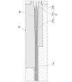
- FIG. 3 is an enlarged view of the fiber hole 11 and its periphery in FIG. 2.
- the fiber hole 11 has a guide portion 11a and a positioning portion 11b.
- the guide portion 11a is located closer to the base end (-Z side) than the positioning portion 11b.
- the inner diameter of the guide portion 11a is larger than the inner diameter of the positioning portion 11b.
- the guide portion 11a functions as a guide to facilitate entry of the bare fiber 21 into the positioning portion 11b.
- the guide portion 11a is not essential.
- the positioning portion 11b functions to define the position of the bare fiber 21. By determining the position of each bare fiber 21 inside the positioning portion 11b, an optical connection between the optical connector 1A and another optical connector is achieved.
- the optical connector to which the optical connector 1A is to be connected may have a so-called multi-core fiber.
- a multi-core fiber is an optical fiber with multiple cores inside one cladding.
- the multi-core fiber may have four cores.
- the optical connector to which the optical connector 1A is to be connected may have the same structure as the optical connector 1A, except for the presence or absence of a positioning pin 40.
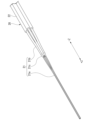
- FIG. 4 is a diagram of the multiple optical fibers 20 shown in FIG. 1.
- the optical connector 1A of this embodiment has four optical fibers 20.
- the number of optical fibers 20 may be changed.
- Each optical fiber 20 has a bare fiber 21 and a coating 22.
- the bare fiber 21 is formed of, for example, quartz glass.
- the bare fiber 21 has a core and a cladding, which are not shown.
- the coating 22 partially covers the bare fiber 21 and serves to protect the bare fiber 21.
- the coating 22 is made of resin or the like.
- the material of the coating 22 may be a UV-curable resin.
- the coating 22 is not provided and the bare fiber 21 is exposed. The exposed bare fiber 21 is inserted into the fiber hole 11 of the ferrule 10.
- the bare fiber 21 has a small diameter portion 21a, a large diameter portion 21b, and a tapered portion 21c.
- the outer diameter of the small diameter portion 21a is smaller than the outer diameter of the large diameter portion 21b.
- the small diameter portion 21a is located at the tip of the bare fiber 21.
- the tapered portion 21c is located between the small diameter portion 21a and the large diameter portion 21b.
- the outer diameter of the tapered portion 21c becomes smaller toward the front.
- the small diameter portion 21a and the tapered portion 21c can be formed by thinning the end of the bare fiber 21, which has a constant outer diameter (the same outer diameter as the large diameter portion 21b) in the longitudinal direction Z, for example by etching.
- the four small diameter portions 21a of the four optical fibers 20 are inserted into one fiber hole 11 of the ferrule 10.
- the bare fiber 21 does not have to have the tapered portion 21c. That is, the bare fiber 21 may have a shape in which the small diameter section 21a and the large diameter section 21b are connected in a step shape.
- the small diameter portion 21a and the tapered portion 21c can be formed by etching the bare fiber 21.
- the bare fiber 21 is quartz glass, hydrofluoric acid or buffered hydrofluoric acid (BHF) may be used as the etching solution.
- BHF buffered hydrofluoric acid
- the material of the bare fiber 21 and the method of forming the small diameter portion 21a and the tapered portion 21c are not limited to the above.
- adhesive 30 is disposed around small diameter portion 21a.
- Adhesive 30 has the function of fixing bare fiber 21 to ferrule 10.
- the volume of adhesive 30 changes when it hardens. For example, when adhesive 30 is heated to harden, adhesive 30 expands thermally and then contracts as it cools. The volume can also change when adhesive 30 is hardened by a chemical reaction. Adhesive 30 is filled inside ferrule 10. Therefore, when the volume of adhesive 30 changes, stress acts on bare fiber 21.
- the thickness of the cladding is small in the small diameter portion 21a.
- the cladding is thin, the light inside the bare fiber 21 is easily affected by the external force that the bare fiber 21 receives. More specifically, the small diameter portion 21a is thin and has low rigidity, so it is easily bent by external forces. This bending can cause light to leak.
- the cladding also has the function of confining light within the core. When the cladding is thin, the function of confining light is weakened, making it easier for light to leak. Light leakage leads to an increase in connection loss between the optical connector 1A and other optical connectors. In other words, a bare fiber 21 with a small diameter portion 21a has the problem that connection loss is easily caused by volumetric changes in the adhesive 30.
- a stress relief material 50 is provided around the small diameter portion 21a.
- the stress relief material 50 is also provided around the tapered portion 21c.
- the stress relief material 50 has the function of relieving the stress acting on the bare fiber 21 due to the volumetric change of the adhesive 30. To perform this function, the stress relief material 50 is made of a material with a smaller Young's modulus than the adhesive 30. Note that the stress relief material 50 and the guide portion 11a are not shown in FIG. 2.
- the stress relaxation material 50 is not provided in the portion of the small diameter portion 21a located in the positioning portion 11b (see FIG. 3) of the fiber hole 11. It is preferable that the stress relaxation material 50 is provided in the portion of the small diameter portion 21a located in the guide portion 11a of the fiber hole 11.
- the reason is as follows. Since the positioning portion 11b has a function of determining the position of the small diameter portion 21a, the gap between the positioning portion 11b and the small diameter portion 21a is very small. By not providing the stress relaxation material 50 inside the positioning portion 11b, it is possible to ensure that the small diameter portion 21a can be easily inserted into the positioning portion 11b. In addition, the volume of the adhesive 30 filled inside the positioning portion 11b is small. Therefore, inside the positioning portion 11b, the effect on the small diameter portion 21a due to the volume change of the adhesive 30 is small. It should be noted that no stress relaxation material 50 is provided on the tip side of the small diameter portion 21a located inside the guide portion 11a.
- the gap between the guide portion 11a and the small diameter portion 21a is larger than the gap between the positioning portion 11b and the small diameter portion 21a. Therefore, even if a stress relief material 50 is provided inside the guide portion 11a, it is possible to ensure that the small diameter portion 21a can be easily inserted into the guide portion 11a. For example, it is possible to determine the inner diameter of the guide portion 11a according to the thickness of the stress relief material 50. In addition, the volume of the adhesive 30 filled inside the guide portion 11a is larger than the volume of the adhesive 30 filled inside the positioning portion 11b. Therefore, inside the positioning portion 11b, the stress relief function of the stress relief material 50 can be effectively exerted.
- the specific Young's modulus of the adhesive 30 is, for example, 500 to 2000 MPa at room temperature.
- the specific Young's modulus of the stress relief material 50 is, for example, 0.4 to 1.5 MPa at room temperature.
- the Young's modulus of the stress relief material 50 is preferably 1/10 or less of the Young's modulus of the adhesive 30.
- Thermosetting resin or UV curing resin may be used as the adhesive 30.
- the adhesive 30 may be an epoxy-based, acrylic-based, or urethane-based resin.
- Thermosetting resin or UV curing resin may be used as the stress relief material 50.
- the stress relief material 50 may be an epoxy-based, acrylic-based, urethane-based, or silicone-based resin.
- the above materials and Young's modulus values are merely examples. If the Young's modulus of the stress relaxation material 50 is smaller than that of the adhesive 30, the effect of relaxing the stress acting on the small diameter portion 21a can be obtained.
- a plurality of optical fibers 20 each having a coating 22 are prepared.
- the coating 22 is partially removed from each of the plurality of optical fibers 20 to expose the bare fibers 21 .
- the exposed part of the bare fiber 21 is thinned by etching or the like. The time for immersion in the etching solution is changed for each position in the longitudinal direction of the bare fiber 21. This allows the small diameter portion 21a and the tapered portion 21c to have any desired outer diameter.
- stress relief material 50 is provided on at least a portion of small diameter portion 21a. Specifically, liquid resin that will become stress relief material 50 is applied to the periphery of small diameter portion 21a. The applied resin is then cured. This forms stress relief material 50 that covers small diameter portion 21a. Here, stress relief material 50 is not provided on the tip of small diameter portion 21a (the portion that is inserted into positioning portion 11b). An example of a method for providing stress relief material 50 partially on small diameter portion 21a in this manner will be described.
- a resin that will become the stress relief material 50 may be applied to the small diameter portion 21a except for the tip, and then cured.
- the resin that will become the stress relief material 50 may be applied to the entire small diameter portion 21a, and the resin may be cured only in the small diameter portion 21a except for the tip.
- the stress relief material 50 is a UV-curable resin
- the tip of the small diameter portion 21a may be masked, and the resin attached to the remaining portion may be cured. The uncured resin may then be removed to leave the tip of the small diameter portion 21a without the stress relief material 50 formed thereon.
- the stress relaxation material 50 may be provided in the tapered portion 21c by the same procedure as above.
- the stress relaxation material 50 may also be provided partially in the large diameter portion 21b.
- a plurality of bare fibers 21 may be processed collectively when forming the stress relaxation material 50.
- the bare fibers 21 are bundled together as shown in Fig. 4.
- a resin that will become the stress relaxation material 50 may be applied collectively to the small diameter portions 21a of the bundled bare fibers 21 and cured.
- the small diameter portions 21 a of the bare fibers 21 provided with the stress relaxation material 50 are inserted into the fiber holes 11 of the ferrule 10 .
- a resin that will become the adhesive 30 is injected through the injection hole 12 and the resin is cured. As a result, the bare fiber 21 is fixed to the ferrule 10.
- the stress relief material 50 is formed on the bare fibers 21 at once. Therefore, as shown in FIG. 6, the stress relief material 50 fills the space between the small diameter sections 21a. In this case, the stress relief material 50 also acts to bundle the small diameter sections 21a together to increase rigidity. This makes it easier to insert the small diameter sections 21a into the fiber holes 11.
- the stress relief material 50 may be formed individually for each bare fiber 21. In this case, as shown in FIG. 5, there may be portions between the small diameter portions 21a where there is no stress relief material 50.
- the optical connector 1A of this embodiment includes a ferrule 10 having a connection end face 10a and a fiber hole 11 opening into the connection end face 10a, a plurality of optical fibers 20 inserted into the fiber hole 11, an adhesive 30 that fixes the plurality of optical fibers 20 to the ferrule 10, and a stress relaxation material 50 having a smaller Young's modulus than the adhesive 30.
- Each of the plurality of optical fibers 20 has a small diameter portion 21a inserted into the fiber hole 11, a large diameter portion 21b having a larger diameter than the small diameter portion 21a, and a tapered portion 21c located between the small diameter portion 21a and the large diameter portion 21b and having a diameter that changes along the longitudinal direction Z.
- the stress relaxation material 50 covers at least a portion of the small diameter portion 21a.
- the fiber hole 11 has a positioning portion 11b that opens into the connection end face 10a, and a guide portion 11a that is located closer to the base end than the positioning portion 11b and has a larger inner diameter than the positioning portion 11b, and the stress relaxation material 50 covers the portion of the small diameter portion 21a that is located inside the guide portion 11a.
- This configuration makes it possible to easily insert the small diameter portion 21a into the fiber hole 11 while also providing a stress relaxation function by the stress relaxation material 50.
- the stress relief material 50 covers the tapered portion 21c.
- the manufacturing method of the optical connector 1A of this embodiment involves preparing multiple optical fibers 20 having a small diameter portion 21a, a tapered portion 21c, and a large diameter portion 21b, bundling the multiple optical fibers 20 together, applying a resin that will become the stress relief material 50 to at least a portion of the small diameter portion 21a, hardening the resin while the multiple optical fibers 20 are bundled together to form the stress relief material 50, and inserting the small diameter portions 21a into the fiber holes 11 of the ferrule 10 while the multiple optical fibers 20 are bundled together, and fixing the multiple optical fibers 20 to the ferrule 10 with an adhesive 30 that has a larger Young's modulus than the stress relief material 50.
- This manufacturing method allows the stress relief material 50 to cover the small diameter portions 21a of the multiple optical fibers 20 as a whole. This increases the rigidity of the bundle of optical fibers 20. This makes it easier to insert the small diameter portions 21a into the fiber holes 11.
- the Young's modulus of the stress relaxation material 50 is smaller than that of the adhesive 30.
- the stress relaxation function of the stress relaxation material 50 may be specified using an index other than Young's modulus.
- the linear expansion coefficient of the stress relaxation material 50 may be smaller than the linear expansion coefficient of the adhesive 30. More specifically, the linear expansion coefficient of the stress relaxation material 50 may be 1/10 or less of the linear expansion coefficient of the adhesive 30.
- the water absorption rate of the stress relief material 50 may be less than the water absorption rate of the adhesive 30. More specifically, the water absorption rate of the stress relief material 50 may be less than half the water absorption rate of the adhesive 30.
Landscapes
- Physics & Mathematics (AREA)
- General Physics & Mathematics (AREA)
- Optics & Photonics (AREA)
- Mechanical Coupling Of Light Guides (AREA)
Priority Applications (1)
| Application Number | Priority Date | Filing Date | Title |
|---|---|---|---|
| JP2025539604A JPWO2025033538A1 (https=) | 2023-08-10 | 2024-08-09 |
Applications Claiming Priority (2)
| Application Number | Priority Date | Filing Date | Title |
|---|---|---|---|
| JP2023-131668 | 2023-08-10 | ||
| JP2023131668 | 2023-08-10 |
Publications (1)
| Publication Number | Publication Date |
|---|---|
| WO2025033538A1 true WO2025033538A1 (ja) | 2025-02-13 |
Family
ID=94534383
Family Applications (1)
| Application Number | Title | Priority Date | Filing Date |
|---|---|---|---|
| PCT/JP2024/028646 Pending WO2025033538A1 (ja) | 2023-08-10 | 2024-08-09 | 光コネクタおよび光コネクタの製造方法 |
Country Status (2)
| Country | Link |
|---|---|
| JP (1) | JPWO2025033538A1 (https=) |
| WO (1) | WO2025033538A1 (https=) |
Citations (10)
| Publication number | Priority date | Publication date | Assignee | Title |
|---|---|---|---|---|
| JPH06337328A (ja) * | 1993-03-29 | 1994-12-06 | Sumitomo Electric Ind Ltd | 光コネクタ |
| US6409394B1 (en) * | 2000-03-21 | 2002-06-25 | Sumitomo Electric Industries, Ltd. | Optical connector |
| WO2012121320A1 (ja) * | 2011-03-09 | 2012-09-13 | 古河電気工業株式会社 | バンドル構造の製造方法、ファイバ接続方法、バンドル端末構造、ファイバの接続構造 |
| JP2013068891A (ja) * | 2011-09-26 | 2013-04-18 | Hitachi Cable Ltd | マルチコアインターフェイスの製造方法及びマルチコアインターフェイス |
| JP2015166818A (ja) * | 2014-03-04 | 2015-09-24 | 住友電気工業株式会社 | 光ファイバ用配列変換アダプタ |
| JP2015175980A (ja) * | 2014-03-14 | 2015-10-05 | 日立金属株式会社 | 光ファイバコネクタ及びその製造方法 |
| WO2016001818A1 (en) * | 2014-07-01 | 2016-01-07 | Tyco Electronics (Shanghai) Co. Ltd. | Ferrule device, apparatus and method for manufacturing the same |
| JP2016061944A (ja) * | 2014-09-18 | 2016-04-25 | 住友電気工業株式会社 | ファンアウト部品 |
| WO2017159710A1 (ja) * | 2016-03-16 | 2017-09-21 | 株式会社フジクラ | 光ファイバ付きフェルール、及び光ファイバ付きフェルールの製造方法 |
| JP2017181791A (ja) * | 2016-03-30 | 2017-10-05 | 古河電気工業株式会社 | 光ファイババンドル構造、光コネクタ、光ファイバ接続構造 |
-
2024
- 2024-08-09 WO PCT/JP2024/028646 patent/WO2025033538A1/ja active Pending
- 2024-08-09 JP JP2025539604A patent/JPWO2025033538A1/ja active Pending
Patent Citations (10)
| Publication number | Priority date | Publication date | Assignee | Title |
|---|---|---|---|---|
| JPH06337328A (ja) * | 1993-03-29 | 1994-12-06 | Sumitomo Electric Ind Ltd | 光コネクタ |
| US6409394B1 (en) * | 2000-03-21 | 2002-06-25 | Sumitomo Electric Industries, Ltd. | Optical connector |
| WO2012121320A1 (ja) * | 2011-03-09 | 2012-09-13 | 古河電気工業株式会社 | バンドル構造の製造方法、ファイバ接続方法、バンドル端末構造、ファイバの接続構造 |
| JP2013068891A (ja) * | 2011-09-26 | 2013-04-18 | Hitachi Cable Ltd | マルチコアインターフェイスの製造方法及びマルチコアインターフェイス |
| JP2015166818A (ja) * | 2014-03-04 | 2015-09-24 | 住友電気工業株式会社 | 光ファイバ用配列変換アダプタ |
| JP2015175980A (ja) * | 2014-03-14 | 2015-10-05 | 日立金属株式会社 | 光ファイバコネクタ及びその製造方法 |
| WO2016001818A1 (en) * | 2014-07-01 | 2016-01-07 | Tyco Electronics (Shanghai) Co. Ltd. | Ferrule device, apparatus and method for manufacturing the same |
| JP2016061944A (ja) * | 2014-09-18 | 2016-04-25 | 住友電気工業株式会社 | ファンアウト部品 |
| WO2017159710A1 (ja) * | 2016-03-16 | 2017-09-21 | 株式会社フジクラ | 光ファイバ付きフェルール、及び光ファイバ付きフェルールの製造方法 |
| JP2017181791A (ja) * | 2016-03-30 | 2017-10-05 | 古河電気工業株式会社 | 光ファイババンドル構造、光コネクタ、光ファイバ接続構造 |
Also Published As
| Publication number | Publication date |
|---|---|
| JPWO2025033538A1 (https=) | 2025-02-13 |
Similar Documents
| Publication | Publication Date | Title |
|---|---|---|
| US8417079B2 (en) | Method of producing a ferrule with an optical fiber | |
| US10627582B2 (en) | Optical connection component and method of manufacturing optical connection component | |
| CN100375670C (zh) | 光连接器套的制造方法与光连接器套制造用的金属模 | |
| CN110178063B (zh) | 光纤保持部件、光连接器及光耦合构造 | |
| JP5290713B2 (ja) | 曲げコネクタ構造およびその作製方法 | |
| JP2012185283A (ja) | 多心光コネクタ、多心光コネクタの製造方法、多心光コネクタ製造用の整列部材 | |
| WO2015093520A1 (ja) | 光接続部品 | |
| WO2012172869A1 (ja) | 光ファイバの接続方法及び光ファイバの接続構造 | |
| WO2020145011A1 (ja) | 光コネクタ及びその製造方法 | |
| CN116224503A (zh) | 光纤束构造、光连接构造体及光纤束构造的制造方法 | |
| JP7613462B2 (ja) | 光ファイバ接続部品及び光ファイバ接続部品の製造方法 | |
| WO2025033538A1 (ja) | 光コネクタおよび光コネクタの製造方法 | |
| JP5547686B2 (ja) | マルチコアファイバ用ファンナウト部品 | |
| TW202223466A (zh) | 光纖連接器構件及其製造方法 | |
| JP5224337B2 (ja) | 光導波路コネクタ及び光導波路コネクタの製造方法 | |
| WO2024171993A1 (ja) | 光コネクタおよび光コネクタの製造方法 | |
| JP2024009665A (ja) | 光ファイババンドル構造、光接続構造体、及び、光ファイババンドル構造の製造方法 | |
| WO2025032947A1 (ja) | 光コネクタ、光コネクタの製造方法、およびフェルールの製造方法 | |
| JP2005309367A (ja) | 光ファイバ接続器と光ファイバ接続体及び光ファイバの接続方法 | |
| JP2005024782A (ja) | 光導波路パッケージ | |
| JP2023082856A (ja) | 光ファイババンドル構造、光接続構造体、及び、光ファイババンドル構造の製造方法 | |
| JP4140276B2 (ja) | 光コネクタの製造方法 | |
| JP7724941B1 (ja) | 光コネクタ、および光接続構造 | |
| WO2025135039A1 (ja) | 光ファイババンドル、光接続構造体、及び、光ファイババンドルの製造方法 | |
| US12535642B2 (en) | Optical fiber bundle connector and method of manufacturing optical fiber bundle connector |
Legal Events
| Date | Code | Title | Description |
|---|---|---|---|
| 121 | Ep: the epo has been informed by wipo that ep was designated in this application |
Ref document number: 24851955 Country of ref document: EP Kind code of ref document: A1 |
|
| ENP | Entry into the national phase |
Ref document number: 2025539604 Country of ref document: JP Kind code of ref document: A |
|
| WWE | Wipo information: entry into national phase |
Ref document number: 2025539604 Country of ref document: JP |
|
| NENP | Non-entry into the national phase |
Ref country code: DE |