WO2025032887A1 - 車両用操舵装置 - Google Patents
車両用操舵装置 Download PDFInfo
- Publication number
- WO2025032887A1 WO2025032887A1 PCT/JP2024/014243 JP2024014243W WO2025032887A1 WO 2025032887 A1 WO2025032887 A1 WO 2025032887A1 JP 2024014243 W JP2024014243 W JP 2024014243W WO 2025032887 A1 WO2025032887 A1 WO 2025032887A1
- Authority
- WO
- WIPO (PCT)
- Prior art keywords
- rotating member
- thread
- axial end
- nut
- axial
- Prior art date
- Legal status (The legal status is an assumption and is not a legal conclusion. Google has not performed a legal analysis and makes no representation as to the accuracy of the status listed.)
- Pending
Links
Images






Classifications
-
- B—PERFORMING OPERATIONS; TRANSPORTING
- B62—LAND VEHICLES FOR TRAVELLING OTHERWISE THAN ON RAILS
- B62D—MOTOR VEHICLES; TRAILERS
- B62D5/00—Power-assisted or power-driven steering
- B62D5/04—Power-assisted or power-driven steering electrical, e.g. using an electric servo-motor connected to, or forming part of, the steering gear
-
- F—MECHANICAL ENGINEERING; LIGHTING; HEATING; WEAPONS; BLASTING
- F16—ENGINEERING ELEMENTS AND UNITS; GENERAL MEASURES FOR PRODUCING AND MAINTAINING EFFECTIVE FUNCTIONING OF MACHINES OR INSTALLATIONS; THERMAL INSULATION IN GENERAL
- F16H—GEARING
- F16H25/00—Gearings comprising primarily only cams, cam-followers and screw-and-nut mechanisms
- F16H25/08—Gearings comprising primarily only cams, cam-followers and screw-and-nut mechanisms for interconverting rotary motion and reciprocating motion
- F16H25/12—Gearings comprising primarily only cams, cam-followers and screw-and-nut mechanisms for interconverting rotary motion and reciprocating motion with reciprocation along the axis of rotation, e.g. gearings with helical grooves and automatic reversal
Definitions
- This disclosure relates to a vehicle steering device.
- a steer-by-wire type vehicle steering device In a steer-by-wire type vehicle steering device, the steering wheel and the steered wheels are mechanically disconnected. In this configuration, the steering reaction force is not transmitted from the steering mechanism, which includes the steered wheels, to the steering wheel. For this reason, a steering reaction force device and a stopper mechanism are provided on the steering shaft that is connected to the steering wheel.
- the steering reaction force device applies a reaction force to the steering wheel in the opposite direction to the direction of rotation (steering direction) of the steering wheel, giving the driver a natural steering feel.
- the steering reaction force device includes, for example, a motor and a reduction mechanism, and the steering reaction force generated by the motor is transmitted to the steering shaft via the reduction mechanism.
- the reduction mechanism includes, for example, a worm shaft and a worm wheel, and the rotation of the motor is transmitted to the worm wheel via the worm shaft as the shaft teeth of the worm shaft mesh with the wheel teeth of the worm wheel.
- the stopper mechanism comprises a rotating member that rotates with the steering wheel and has a male thread on its outer periphery, a nut that has a female thread on its inner periphery and moves linearly in the axial direction relative to the rotating member, and a stopper portion that stops the linear movement of the nut.
- the rotating member has a male thread portion and a cylindrical surface portion adjacent to the male thread portion in the axial direction.
- the stopper portion has an annular member that fits onto the outer periphery of the cylindrical surface portion, and a leaf spring that fits onto the outer periphery of the annular member.
- the male thread portion has a complete thread portion and an incomplete thread portion adjacent to both sides of the complete thread portion in the axial direction. Since an incomplete thread has less strength than a complete thread, in Patent Document 1, a cylindrical surface portion is provided at a position axially outward and inner than the axial end of the incomplete thread portion so that the annular member and leaf spring do not come into contact with the incomplete thread. For this reason, the stopper mechanism portion in Patent Document 1 is large in the axial direction, which may result in an increase in the size of the vehicle steering device.
- This disclosure was made in consideration of the above-mentioned problems, and aims to provide a more compact vehicle steering device.
- a vehicle steering device in which a steering wheel and steered wheels are mechanically disconnected, and includes a stopper mechanism that regulates the range of rotation angle of the steering wheel when the steering wheel is rotated, and the stopper mechanism includes a male thread portion having a male thread including a complete thread and an incomplete thread provided on its outer periphery, and a pair of cylindrical surface portions adjacent to the male thread portion on one and the other sides in the axial direction of a central axis and having a cylindrical surface with a diameter smaller than the outer diameter of the male thread portion, and includes a rotating member that rotates in a circumferential direction around the central axis in response to the rotation of the steering wheel, a nut that is provided on its inner periphery with a female thread that meshes with the male thread and that moves in the axial direction relative to the rotating member as the rotating member rotates, and a stopper mechanism that is inserted into each of the pair of cylindrical surface portions of the rotating member and
- the housing is arranged on the outer circumferential side of the rotating member, the nut, and the pair of annular members, and supports each of the pair of annular members between the rotating member and the nut.
- a first incomplete thread is arranged at one end in the axial direction
- a second incomplete thread is arranged at the other end in the axial direction
- the complete thread is arranged between the first incomplete thread and the second incomplete thread.
- the first incomplete thread has an axial end surface extending along a first plane perpendicular to the central axis and a separated portion spaced apart from the first plane to the other side in the axial direction.
- the second incomplete thread has an axial end surface extending along a second plane perpendicular to the central axis and a separated portion spaced apart from the second plane to the one side in the axial direction.
- an incomplete thread has less strength than a complete thread, so a cylindrical surface portion is provided at a position axially outward and inner than the axial end of the incomplete thread portion to prevent the annular member and leaf spring from hitting the incomplete thread. Then, an annular member is fitted into the cylindrical surface portion, and a leaf spring is fitted on the outer periphery of the annular member. For this reason, the stopper mechanism of Patent Document 1 is large in the axial direction, which may result in an increase in the size of the vehicle steering device.
- the axial end face portion on one side of the axial direction of the first incomplete thread abuts against the nut side end face of the vertical wall portion of the annular member
- the axial end face portion on the other side of the axial direction of the second incomplete thread abuts against the nut side end face of the vertical wall portion of the annular member
- the portion of the annular member that abuts the axial end face bulges toward the nut, while the portion facing the separation portion does not change in thickness. Therefore, when viewed from the side, the annular member is compressed but does not exhibit rotational behavior. Therefore, compared to the case where the annular member does not rotate (oscillate), the reaction force exerted by the annular member on the first incomplete thread and the second incomplete thread is smaller, making the first incomplete thread and the second incomplete thread less likely to be damaged.
- the rotating member is pushed out in the opposite direction to the movement direction of the nut, compressing the annular member, and the reaction force causes the annular member to push back the incomplete thread portion, thereby further reducing the force that the annular member exerts on the first and second incomplete threads.
- This makes it possible to abut the annular member against the first and second incomplete threads.
- the axial size can be set smaller than in Patent Document 1, and thus it is possible to provide a more compact vehicle steering device.
- the axial end surface portion of the first incomplete thread and the axial end surface portion of the second incomplete thread are positioned on the same side of the central axis.
- the axial end surface portion of the first incomplete thread and the axial end surface portion of the second incomplete thread are positioned on opposite sides of the central axis.
- the axial end face portion of the first incomplete thread and the axial end face portion of the second incomplete thread are arranged on opposite sides of the central axis. Therefore, compared to when the axial end face portion of the first incomplete thread and the axial end face portion of the second incomplete thread are arranged on the same side of the central axis, the behavior is the opposite, and the reaction force of the vertical wall portion against the compression causes the rotating member to swing in a clockwise direction when viewed from the radial direction.
- a local load may be applied to a specific part of the annular member, but for example, if the rotating member is rotated, for example, 180 degrees around the central axis after a predetermined period of time has elapsed, the local load is prevented from continuing to be applied to a specific part of the annular member.
- At least one of the pair of annular members has a main body and a coating layer provided on the surface of the main body, and the elastic modulus of the coating layer is smaller than the elastic modulus of the main body.
- a material that reduces the friction coefficient with the mating material may be selected for the coating layer to prevent the nut from getting caught when it comes into contact.
- Grease lubrication may also be used instead of the coating layer.
- At least one of the pair of annular members has a protruding portion that protrudes axially toward the nut and can abut against the nut.
- the distance the nut can move in the axial direction is reduced compared to an annular member that does not have a protruding portion. This reduces the limit range of the steering angle of the steered wheels, making it possible to set the angle at which the steering wheel can be turned smaller.
- the housing has a cylindrical housing body portion that extends circumferentially and a sealing portion that seals one axial side of the housing body portion.
- the housing is sealed by the sealing portion, which prevents foreign matter such as dust from entering the inside of the housing. It also prevents oil inside the housing from leaking out to the outside.
- the housing has a cylindrical housing main body portion that extends circumferentially and is open on one axial side, a protrusion portion that is disposed at one axial end of the housing main body portion and has a recess that protrudes to the inner periphery and is recessed to the outer periphery, and a seal member that is accommodated in the recess, and the annular member is disposed on the inner periphery side of the recess of the protrusion portion, and the tip of the inner periphery side of the seal member is capable of abutting against the outer periphery surface of the annular member.
- the housing main body has an opening, which can allow dust and other foreign matter to enter the housing from the opening into the inside.
- the tip of the sealing member abuts against the annular member, making it possible to prevent foreign matter from entering.
- the sealing member also prevents oil from inside the housing from leaking out to the outside.
- This disclosure makes it possible to provide a more compact vehicle steering device.
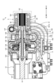
- FIG. 1 is a schematic diagram showing the overall configuration of a vehicle steering system according to a first embodiment.
- FIG. 2 is a cross-sectional view showing a part of FIG.
- FIG. 3 is a cross-sectional view showing a part of FIG.
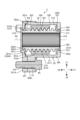
- FIG. 4 is a cross-sectional view of the stopper mechanism according to the first embodiment.
- FIG. 5 is an enlarged cross-sectional view of a portion of FIG.
- FIG. 6 is an exploded perspective view of the stopper mechanism according to the first embodiment.
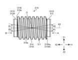
- FIG. 7 is a perspective view of the rotating member of FIG.
- FIG. 8 is a side view of the rotating member of FIG.
- FIG. 9 is a schematic diagram of the rotating member in FIG. 8 as viewed from the direction A.
- FIG. 10 is a schematic diagram of the rotating member in FIG.
- FIG. 11 is a side view of a rotating member according to a modified example.
- FIG. 12 is a schematic diagram of the rotating member of FIG. 11 as viewed from the direction A.
- FIG. 13 is a schematic diagram of the rotating member in FIG. 11 as viewed from the direction B.
- FIG. 14 is a cross-sectional view of the stopper mechanism according to the second embodiment.
- 15 is an enlarged cross-sectional view of the first annular member of FIG. 14.
- FIG. FIG. 16 is a cross-sectional view of a stopper mechanism according to the third embodiment.
- FIG. 17 is a cross-sectional view of the stopper mechanism according to the fourth embodiment.
- FIG. 18 is a cross-sectional view of a stopper mechanism according to the fifth embodiment.
- the form (embodiment) for carrying out the present invention will be described in detail with reference to the drawings.
- the present invention is not limited to the contents described in the following embodiment.
- the components described below include those that a person skilled in the art can easily imagine and those that are substantially the same.
- the components described below can be combined as appropriate.
- parts with the same structure are given the same reference numerals and their explanation will be omitted.
- the X direction indicates the axial direction of the rotating member
- the X1 side is one side in the axial direction
- the X2 side is the other side in the axial direction.
- FIG. 1 is a schematic diagram showing an overall configuration of a vehicle steering device according to the first embodiment.
- Fig. 2 is a cross-sectional view showing a part of Fig. 1.
- Fig. 3 is a cross-sectional view showing a part of Fig. 2.
- the vehicle steering device 100 includes a steering unit 4, a control device (ECU) 14, and a steering unit 20.
- ECU control device
- the steering unit 4 is provided with a steering reaction device 13.
- the steering reaction device 13 applies a steering reaction force to the steering wheel 10 in the opposite direction to the direction of rotation of the steering wheel 10.
- the control device (ECU) 14 calculates a reaction torque according to the vehicle's running state based on the operation information, adjusts the power value supplied to the motor 110 of the steering reaction device 13 based on the reaction torque, and the motor 110 operates according to the power value, thereby transmitting the steering reaction force of the steering wheel 10 to the operator.
- the steering wheel 10 and the steered wheels 22 are mechanically uncoupled.
- "uncoupled” also includes a mode in which the steering wheel 10 and the steered wheels 22 can be coupled by a clutch device or the like in an emergency, for example.
- the control device (ECU) 14 also calculates a current command value based on the operation information and controls the current supplied to the steering motor 21 of the steering unit 20.
- the steered wheels 22 are steered via various gears connected to the steering motor 21.
- Each component of the vehicle steering device 100 will be described in detail below.
- the steering unit 4 includes a steering wheel 10, a steering shaft 11, a steering housing 12, and a steering reaction device 13.
- the steering shaft 11 extends in the X direction (axial direction).
- the steering wheel 10 is rotatably connected to the steering shaft 11.
- the steering shaft 11 is housed inside the steering housing 12.
- the steering shaft 11 has a column shaft 15, an output shaft 16, and a torsion bar 17.
- the column shaft 15 and the output shaft 16 are connected via a torsion bar 17. Specifically, an insertion hole is provided in the axial direction at the X1 side end of the column shaft 15, and the torsion bar 17 is inserted into this insertion hole.
- the column shaft 15 and the torsion bar 17 are connected to each other via a pin 122 so that they cannot rotate relative to each other.
- a through hole that passes through the output shaft 16 in the axial direction is provided, and the X1 side end of the torsion bar 17 is fitted into this through hole. In this way, the output shaft 16 and the torsion bar 17 are connected to each other so that they cannot rotate relative to each other. As a result, when the steering wheel 10 is rotated, the steering shaft 11 also rotates.
- the steering housing 12 also includes a shaft holding member 121, rotation support members 123 and 124, and a sub-housing 127.
- the rotation support member 123 is located on the X1 side of the shaft holding member 121, and the rotation support member 124 is located on the X1 side of the rotation support member 123.
- the sub-housing 127 is located on the X1 side of the rotation support member 124.
- a bearing 125 is provided on the radial inside of the rotation support member 124, and a bearing 126 is provided on the radial inside of the sub-housing 127.
- the output shaft 16 is rotatably supported via the bearings 125 and 126.
- a torque sensor 128 is provided between the rotation support member 123 and the rotation support member 124. The torque sensor 128 detects the rotation torque transmitted between the column shaft 15 and the output shaft 16.
- the steering reaction force device 13 has a steering shaft 11, a worm wheel 18, a worm shaft 19, and a motor 110.
- a worm wheel 18 is attached to the outer periphery of the output shaft 16 of the steering shaft 11.
- the worm wheel 18 has a core metal portion 18a and a wheel tooth portion 18b.
- the wheel tooth portion 18b is provided on the outer periphery of the core metal portion 18a.
- a worm shaft 19 and a motor 110 are located on the Y2 side (see Figure 6) of the worm wheel 18.
- the worm shaft 19 is attached to the output shaft of the motor 110.
- the worm shaft 19 has a shaft tooth portion 19a.
- the shaft tooth portion 19a meshes with the wheel tooth portion 18b.
- the motor 110 is the source of the steering reaction force. In other words, the output of the motor 110 becomes a reaction torque, and the reaction torque is transmitted from the steering shaft 11 to the steering wheel 10 via the worm wheel 18 and the worm shaft 19.
- the rotating member 31 has a central axis AX, and the axial direction of the central axis AX coincides with the X direction.
- the rotating member 31 included in the stopper mechanism unit 3 is spline-fitted to the X1 side end of the output shaft 16 of the steering shaft 11. That is, a female spline 319 extending in the X direction is provided on the inner circumference side of the rotating member 31, and a male spline extending in the X direction is provided on the outer circumference side of the X1 side end of the output shaft 16.
- the male spline of the output shaft 16 is fitted into the female spline 319 of the rotating member 31.
- the rotating member 31 can move in the X direction relative to the output shaft 16 and cannot rotate in the circumferential direction around the central axis AX. That is, the rotating member 31 rotates integrally with the output shaft 16.
- Figure 4 is a cross-sectional view of the stopper mechanism according to the first embodiment.
- Figure 5 is a cross-sectional view of an enlarged portion of Figure 4.
- Figure 6 is an exploded perspective view of the stopper mechanism according to the first embodiment.
- the stopper mechanism 3 includes a rotating member 31, a nut 32, a first annular member 331, a second annular member 331A, and a housing 35.
- the rotating member 31 has a central axis AX.
- the axial direction of the central axis AX is the X direction.
- the direction around the central axis AX is the circumferential direction.
- the direction perpendicular to the central axis AX is the radial direction.
- the rotating member 31 has a male threaded portion 311, a first cylindrical surface portion 312, and a second cylindrical surface portion 312A.
- the male thread portion 311 has a male thread 310 on its outer periphery.
- the male thread 310 has a bottom portion 310a.
- the male thread 310 includes a complete thread 314, a first incomplete thread 315, and a second incomplete thread 316.
- the first incomplete thread 315 is located at the end closest to the X1 side
- the second incomplete thread 316 is located at the end closest to the X2 side.
- the first cylindrical surface portion 312 is adjacent to the male thread portion 311 on the X1 side.
- the first cylindrical surface portion 312 has a cylindrical surface 313.
- the cylindrical surface 313 extends in the circumferential direction around the central axis AX.
- the diameter of the cylindrical surface 313 is smaller than the outer diameter of the male thread portion 311.
- the second cylindrical surface portion 312A is adjacent to the male thread portion 311 on the X2 side.
- the second cylindrical surface portion 312A has a cylindrical surface 313.
- the end of the rotating member 31 on the X1 side has an axial end face 317, and the end of the rotating member 31 on the X2 side has an axial end face 318.
- the rotating member 31 will be described in more detail later.
- the nut 32 is provided on the outer periphery of the rotating member 31.
- the nut 32 has a female thread 321 on the inner periphery.
- the female thread 321 meshes with the male thread 310 of the rotating member 31.
- the outer periphery 324 of the nut 32 is a cylindrical surface extending in the circumferential direction.
- the end of the nut 32 on the X1 side has an axial end face 322, and the end of the nut 32 on the X2 side has an axial end face 323.
- the axial end face 322 of the nut 32 can abut against the vertical wall portion 332 of the first annular member 331.
- the axial end face 323 of the nut 32 can abut against the vertical wall portion 332A of the second annular member 331A.
- the first annular member 331 has an annular shape extending in the circumferential direction.
- the first annular member 331 is inserted into the first cylindrical surface portion 312.
- the inner diameter of the first annular member 331 is larger than the outer diameter of the first cylindrical surface portion 312. Therefore, the first annular member 331 can move in the X direction while inserted into the first cylindrical surface portion 312.
- the first annular member 331 has a vertical wall portion 332 and a tube portion 333.
- the vertical wall portion 332 extends radially outward.
- the tube portion 333 extends in the circumferential direction.
- the vertical wall portion 332 and the tube portion 333 are connected via a corner portion 334.
- the second annular member 331A is inserted into the second cylindrical surface portion 312A.
- the second annular member 331A has a vertical wall portion 332A and a tube portion 333A.
- the vertical wall portion 332A extends radially outward.
- the vertical wall portion 332A is positioned facing the X2 side of the nut 32.
- the tube portion 333A extends in the circumferential direction.
- the vertical wall portion 332A and the tube portion 333A are connected via a corner portion 334A.
- the housing 35 is disposed on the outer periphery of the rotating member 31, the nut 32, the first annular member 331, and the second annular member 331A.
- the housing 35 includes a first housing 351 and a second housing 352.
- the first housing 351 is disposed on the X2 side of the housing 35.
- the first housing 351 has a connecting portion 351a, a vertical wall portion 351b, a cylindrical portion 351c, and a flange 351d.
- the coupling portion 351a fits into the coupled portion 352a of the second housing 352 and is coupled to the coupled portion 352a.
- the vertical wall portion 351b extends in the radial direction, and the cylindrical portion 351c extends in the circumferential direction.
- a second bolt hole H2 is provided in the flange 351d.
- a female thread is provided on the inner periphery of the second bolt hole H2, and the female thread engages with the male thread of the bolt BL.
- the second housing 352 has a connecting portion 352a, a cylindrical portion 352b, a radial wall portion 352c, and a flange 352h.
- the cylindrical portion 352b extends in the circumferential direction.
- the radial wall portion 352c extends in the radial direction.
- a through hole 353 is provided in the radial center of the radial wall portion 352c, and the first annular member 331 and the rotating member 31 are fitted into the through hole 353.
- the flange 352h is provided with a first bolt hole H1.
- a through hole is provided on the inner circumference of the first bolt hole H1, and the shank of the bolt BL passes through the through hole. Therefore, the flanges 351d and 352h are fastened via the bolt BL.
- the outer diameters of the first annular member 331 and the second annular member 331A are both a first outer diameter D1.
- a first radial distance between the outer peripheral end of the vertical wall portion 332 of the first annular member 331 and the central axis AX is the same as a second radial distance between the outer peripheral end of the vertical wall portion 332A of the second annular member 331A and the central axis AX.
- the first outer diameter D1 is twice the first distance or twice the second distance.
- the outer diameter of the cylindrical surface 313 is a second outer diameter D2.
- the second outer diameter D2 is the same as the diameter of the bottom portion 310a of the male thread 310.
- the first outer diameter D1 is larger than the second outer diameter D2.
- the rotating member 31 is fastened to the inner periphery of the nut 32, the first annular member 331 is inserted into the first cylindrical surface portion 312 of the rotating member 31, and the second annular member 331A is inserted into the second cylindrical surface portion 312A.
- the rotating member 31, the nut 32, the first annular member 331, and the second annular member 331A are inserted into the inside of the second housing 352.
- the protrusion 325 is fitted into the groove portion 352j.
- the first housing 351 is bolted to the second housing 352.
- the flange 351d is butted against the flange 352h, and the second bolt hole H2 and the first bolt hole H1 are communicated. Then, the bolt BL is passed through the first bolt hole H1 and engaged with the female thread of the second bolt hole H2, completing the assembly of the stopper mechanism 3. As described above, the protrusion 325 of the nut 32 fits into the groove 352j of the second housing 352, so the nut 32 moves linearly in the X direction without rotating relative to the second housing 352.
- FIG. 7 is a perspective view of the rotating member of Fig. 6.
- Fig. 8 is a side view of the rotating member of Fig. 6.
- Fig. 9 is a schematic diagram of the rotating member of Fig. 8 as viewed from direction A.
- Fig. 10 is a schematic diagram of the rotating member of Fig. 8 as viewed from direction B.
- the axial end surface portion 315a and the axial end surface portion 316a are provided on the same side, that is, the Z1 side, with respect to the straight line L perpendicular to the central axis AX, as shown in Figures 9 and 10.
- the straight line L extends in the Y direction.
- the first incomplete thread 315 is disposed at the end of the male thread portion 311 closest to the X1 side.
- the axial end surface portion 315a on the X1 side of the first incomplete thread 315 is the hatched portion shown in Figure 9.
- the axial end surface portion 315a extends radially along a first plane perpendicular to the central axis AX.
- the axial end surface portion 315a is provided on the Z1 side of the circumferential direction of the male thread portion 311. Specifically, the axial end surface portion 315a extends over half a circumference from the Y1 side through the Z1 side to the Y2 side.
- the Y direction is a radial direction perpendicular (intersecting) to the X direction (axial direction)
- the Z direction is a radial direction perpendicular (intersecting) to the X direction and the Y direction.
- the Y1 side is one side of the Y direction
- the Y2 side is the other side of the Y direction.
- the Z1 side is one side of the Z direction
- the Z2 side is the other side of the Z direction.
- the radial width is smallest on the Y1 side, gradually increases from the Y1 side to the Z1 side, and is maximum on the Z1 side. Then, the width gradually decreases toward the Y2 side, and is minimum on the Y2 side.
- the radial width on the Z1 side is the same as the width of the complete thread 314 shown in FIG. 9.
- the separated portion 315b other than the hatched portion shown in FIG. 9 is located on the opposite side across the central axis AX in FIG. 9. That is, it extends in the circumferential direction from the Y1 side through the Z2 side to the Y2 side over half a circumference.
- an "incomplete thread” refers to a "thread portion with an incomplete thread shape created by the chamfered portion or the chamfered portion of the thread processing tool" (see JIS B 0101).
- the hatched axial end surface portion 315a abuts against the first plane.
- the separation portion 315b is spaced from the first plane toward the X2 side (the axial center side of the rotating member 31).
- the axial end surface portion 315a is located on the opposite side of the separation portion 315b with respect to the straight line L perpendicular to the central axis AX.
- a second incomplete thread 316 is disposed at the end of the male thread 311 closest to the X2 side.
- the axial end surface 316a of the second incomplete thread 316 on the X2 side is the hatched portion shown in FIG. 10.
- the axial end surface 316a extends radially along a second plane perpendicular to the central axis AX.
- the axial end surface 316a is provided on the Z1 side of the circumferential direction of the male thread 311. Specifically, the axial end surface 316a extends over half a circumference from the Y2 side through the Z1 side to the Y1 side.
- the radial width is smallest on the Y2 side, gradually increases from the Y2 side to the Z1 side, and is largest on the Z1 side. Then, the width gradually decreases as it approaches the Y1 side, and is smallest at Y1.
- the separated portion 316b shown in FIG. 10 is located on the opposite side of the axial end surface portion 316a with respect to a straight line L perpendicular to the central axis AX. In other words, the separated portion 316b extends in the circumferential direction over half a circumference from the Y2 side through the Z2 side to the Y1 side.
- the hatched axial end surface portion 316a abuts against the second plane.
- the separation portion 315b shown in FIG. 10 is separated from the second plane toward the X2 side (the axial center side of the rotating member 31).
- the axial end surface portion 316a is located on the opposite side of the separation portion 316b with respect to the straight line L perpendicular to the central axis AX.
- the rotating member 31 has the axial end surface portion 315a and the axial end surface portion 316a at both ends in the X direction.
- the axial end surface portion 315a and the axial end surface portion 316a are both provided over approximately half the circumference on the Z1 side, which is the same side in the circumferential direction.
- the axial end surface portion 315a and the axial end surface portion 316a are provided on the Z1 side, which is the same side, with respect to the straight line L perpendicular to the central axis AX.
- FIG. 11 is a side view of the rotating member according to the modified example.
- FIG. 12 is a schematic diagram of the rotating member of FIG. 11 as viewed from direction A.
- FIG. 13 is a schematic diagram of the rotating member of FIG. 11 as viewed from direction B.
- the axial end surface portion 315Aa and the axial end surface portion 316a are provided on the Z2 side and the Z1 side, which are opposite sides of the straight line L perpendicular to the central axis AX.
- the first incomplete thread 315A is disposed at the end of the male thread portion 311 closest to the X1 side.
- the axial end surface portion 315Aa on the X1 side of the first incomplete thread 315A is the hatched portion shown in FIG. 12.
- the axial end surface portion 315Aa extends radially along a first plane perpendicular to the central axis AX.
- the axial end surface portion 315Aa is provided on the Z2 side of the circumferential direction of the male thread portion 311. Specifically, the axial end surface portion 315Aa extends over half a circumference from the Y1 side through the Z2 side to the Y2 side. The radial width is smallest on the Y1 side, gradually increases from the Y1 side to the Z2 side, and is largest on the Z2 side. The width then gradually decreases toward the Y2 side, and is smallest at Y2.
- the separated portion 315Ab shown in FIG. 12 is located on the opposite side of the axial end surface portion 315Aa with respect to the straight line L perpendicular to the central axis AX. That is, the separated portion 315Ab extends circumferentially over half a circumference from the Y1 side through the Z1 side to the Y2 side.
- the hatched axial end surface portion 315Aa abuts against the first plane.
- the separation portion 315Ab shown in FIG. 12 is separated from the first plane on the X2 side (the axial center side of the rotating member 31A).
- a second incomplete thread 316 is disposed at the end of the male thread portion 311 closest to the X2 side.
- the axial end surface portion 316a on the X2 side of the second incomplete thread 316 is the hatched portion shown in FIG. 13.
- the axial end surface portion 316a extends radially along a second plane perpendicular to the central axis AX.
- the axial end surface portion 316a shown in FIG. 13 is the same as the axial end surface portion 316a shown in FIG. 10 described above.
- the rotating member 31A has the axial end surface portion 315Aa and the axial end surface portion 316a at both ends in the X direction.
- the axial end surface portion 315Aa and the axial end surface portion 316a are provided over approximately half the circumference on the Z2 side and the Z1 side, which are opposite sides in the circumferential direction.
- the axial end surface portion 315Aa and the axial end surface portion 316a are provided on the Z2 side and the Z1 side, which are opposite sides of the straight line L perpendicular to the central axis AX.
- the stopper mechanism 3 includes the rotating member 31 having the male thread portion 311 and a pair of cylindrical surface portions (first cylindrical surface portion 312 and second cylindrical surface portion 312A), the nut 32 moving in the X direction (axial direction) relative to the rotating member 31, a pair of annular members (first annular member 331 and second annular member 331A) inserted into each of the pair of cylindrical surface portions of the rotating member 31, and the housing 35.
- the annular members have flat vertical wall portions 332, 332A.
- the first incomplete thread 315 is disposed at the end on the X1 side (one side in the axial direction), and the second incomplete thread 316 is disposed at the end on the X2 side (the other side in the axial direction).
- the surface on the X1 side of the first incomplete thread 315 is provided with an axial end surface portion 315a and a separation portion 315b.
- the X2 side surface of the second incomplete thread 316 has an axial end surface portion 316a and a separation portion 316b.
- an incomplete thread has less strength than a complete thread, so a cylindrical surface portion is provided at a position axially outward and inner than the axial end of the incomplete thread portion to prevent the annular member and leaf spring from hitting the incomplete thread. Then, an annular member is fitted into the cylindrical surface portion, and a leaf spring is fitted on the outer periphery of the annular member. For this reason, the stopper mechanism of Patent Document 1 is large in the axial direction, which may result in an increase in the size of the vehicle steering device.
- the axial end surface 315a on the X1 side of the first incomplete thread 315 abuts against the end surface on the X2 side of the vertical wall portion 332 of the first annular member 331, and the axial end surface 316a on the X2 side of the second incomplete thread 316 abuts against the end surface on the X1 side of the vertical wall portion 332A of the second annular member 331A.
- the stopper mechanism 3 when the nut 32 moves to the X1 side due to the rotation of the rotating member 31, the vertical wall portion 332A of the second annular member 331A pushes back the axial end face portion 316a of the second incomplete thread 316 to the X1 side, but the separation portion 316b does not abut against the vertical wall portion 332A. Also, when the nut 32 moves to the X2 side due to the rotation of the rotating member 31, the vertical wall portion 332 of the first annular member 331 pushes back the axial end face portion 315a of the first incomplete thread 315 to the X2 side, but the separation portion 315b does not abut against the vertical wall portion 332. In this way, in the stopper mechanism 3 according to this embodiment, the first annular member 331 abuts against the first incomplete thread 315 of the rotating member 31, and the second annular member 331A abuts against the second incomplete thread 316.
- the stopper mechanism 3 in this embodiment can be set to a smaller axial size, making it possible to provide a more compact vehicle steering device 100.
- the swinging direction R2 is a direction that goes counterclockwise (left-handed) around the center O when the rotating member 31 is viewed from the Y1 side.
- the rotating member 31 when the nut 32 moves to the X1 side and when the rotating member 31 moves to the X2 side, the direction of oscillation of the rotating member 31 as viewed from the Y1 side is opposite to each other, so that the load is applied evenly to the first annular member 331 and the second annular member 331A, thereby improving the durability of the first annular member 331 and the second annular member 331A.
- the swing direction of the rotating member 31A according to the modified example will be described.
- the axial end surface portion 315Aa of the first incomplete thread 315A and the axial end surface portion 316a of the second incomplete thread 316 are arranged on the Z2 side and the Z1 side, which are opposite each other with respect to the straight line L perpendicular to the central axis AX, when viewed from the X direction.
- the swing direction R2 is a direction that goes in a counterclockwise direction (left-handed direction) around the center O when the rotating member 31A is viewed from the Y1 side.
- the rotating member 31A swings in the swing direction R1 regardless of whether the nut 32 moves to the X1 side or the X2 side.
- the rotating member 31A swings in the swing direction R1
- a detailed explanation will be given below.
- the separation portion 316b moves in a direction approaching the vertical wall portion 332A.
- the separation portion 316b is located on the X1 side of the axial end surface portion 316a, a gap is generated between the separation portion 316b and the vertical wall portion 332A. Therefore, the separation portion 316b is more likely to approach the vertical wall portion 332A of the second annular member 331A, making it easier for the rotating member 31A to swing in the swing direction R1.
- the separation portion 315Ab moves in a direction approaching the vertical wall portion 332.
- the separation portion 315Ab is located on the X2 side of the axial end surface portion 315Aa, a gap is generated between the separation portion 315Ab and the vertical wall portion 332. Therefore, the separation portion 315Ab can easily approach the vertical wall portion 332 of the first annular member 331, and the rotating member 31A can easily swing in the swing direction R1.
- Fig. 14 is a cross-sectional view of a stopper mechanism according to the second embodiment.
- Fig. 15 is an enlarged cross-sectional view of the first annular member of Fig. 14.
- the stopper mechanism 3A according to the second embodiment differs from the stopper mechanism 3 according to the first embodiment in that the first annular member 331B is different.
- the first annular member 331B has a vertical wall portion 332 and a tubular portion 333.
- Each of the vertical wall portion 332 and the tubular portion 333 has a main body portion 338 and a coating layer 339.
- the coating layer 339 is provided on the surface layer of the main body 338.
- the main body 338 is, for example, a metal, and the coating layer 339 is, for example, a resin.
- the elastic modulus of the main body 338 is, for example, 205 GPa.
- the elastic modulus of the coating layer 339 is, for example, 650 MPa. In this way, the elastic modulus of the coating layer 339 is smaller than the elastic modulus of the main body 338.
- the first annular member 331B and the second annular member 331C include a main body 338 and a coating layer 339 provided on the surface of the main body 338.
- the elastic coefficient of the coating layer 339 is smaller than the elastic coefficient of the main body 338. This makes it possible to reduce the contact noise (interference noise) generated when the nut 32 contacts the first annular member 331B or the second annular member 331C.
- a material that reduces the friction coefficient with the mating material may be selected for the coating layer 339 to prevent the nut from getting caught when it contacts the mating material.
- Grease lubrication may also be used instead of the coating layer.
- Fig. 16 is a cross-sectional view of a stopper mechanism according to the third embodiment.
- the stopper mechanism 3B according to the third embodiment differs from the stopper mechanism 3 according to the first embodiment in the first annular member 331D and the second annular member 331E.
- the first annular member 331 according to the first embodiment has a vertical wall portion 332 and a cylindrical portion 333.
- the first annular member 331D according to the third embodiment further has a protruding portion 336. That is, the first annular member 331D has a vertical wall portion 332, a cylindrical portion 333, and a protruding portion 336.
- the protruding portion 336 extends in the circumferential direction.
- the protruding portion 336 extends from the radially outer end of the vertical wall portion 332 to the X2 side.
- the second annular member 331E has a vertical wall portion 332A, a tubular portion 333A, and a protruding portion 337.
- the protruding portion 337 extends in the circumferential direction.
- the protruding portion 337 extends from the radially outer end of the vertical wall portion 332A toward the X1 side.
- the first annular member 331D has a protruding portion 336 that protrudes toward the nut side in the X direction (axial direction) and can abut against the nut 32.
- the second annular member 331E has a protruding portion 337 that protrudes toward the nut side in the X direction (axial direction) and can abut against the nut 32.
- the first annular member 331D and the second annular member 331E each have a protruding portion 336 or a protruding portion 337 that protrudes toward the nut in the X direction and can abut against the nut 32.
- the distance that the nut 32 can move in the X direction is smaller than the first annular member 331 and the second annular member 331A that do not have the protrusion 336 or the protrusion 337 in the first embodiment. This makes it possible to reduce the limit range of the steering angle of the steered wheels 22 and set the rotatable angle of the steering wheel 10 to a smaller value.
- FIG. 17 is a cross-sectional view of a stopper mechanism according to the fourth embodiment.
- the stopper mechanism 3C according to the fourth embodiment differs from the stopper mechanism 3 according to the first embodiment in the radial wall portion 352c. This is explained in detail below.
- the housing 35A has a cylindrical portion 352b (housing main body portion) and a sealing portion 352g that seals the X1 side of the cylindrical portion 352b.
- the end portion on the X1 side is sealed by the sealing portion 352g.
- the housing 35A has a cylindrical portion 352b (housing main body) that extends in the circumferential direction, and a sealing portion 352g that seals the X1 side of the cylindrical portion 352b.
- the housing 35A is sealed by the sealing portion 352g, so that foreign matter such as dust can be prevented from entering the inside of the housing 35A.
- the oil inside the housing 35A can be prevented from leaking out to the outside.
- Fig. 18 is a cross-sectional view of a stopper mechanism according to the fifth embodiment.
- a seal member S is provided in the housing 35B.
- the second housing 352B has a protrusion 352Bd at the end on the X1 side.
- a recess 354 is provided on the inner periphery of the protrusion 352Bd.
- the recess 354 extends in an annular shape along the circumferential direction. In the cross section shown in FIG. 18, the recess 354 has a generally trapezoidal shape whose distance in the X direction decreases as it moves radially outward.
- An annular seal member S is housed inside the recess 354.
- the first annular member 331F also has a vertical wall portion 332 and a tubular portion 333F.
- the first annular member 331F differs from the first annular member 331 in that the tubular portion 333F is different. Specifically, the distance in the X direction of the tubular portion 333F of the first annular member 331F is greater than the distance in the X direction of the tubular portion 333 of the first annular member 331.
- the tubular portion 333F seals the opening on the inner periphery side of the recess 354.
- the tip S10 on the inner periphery side of the seal member S abuts against the tubular portion 333F.
- the second housing 352B has a protrusion 352Bd in which a recess 354 is provided, and an annular seal member S is housed in the recess 354.
- the inner peripheral end S10 of the seal member S abuts against the tubular portion 333F.
- a through hole 353 is provided in the radial wall portion 352c of the second housing 352B.
- the sealing member S can prevent oil inside the second housing 352B from leaking out to the outside. There is also the possibility that foreign matter such as dust may enter the inside of the second housing 352B through the through hole 353. However, because the tip S10 of the sealing member S abuts against the first annular member 331F, it is possible to prevent the entry of such foreign matter.
- Steering unit 10 Steering wheel 11 Steering shaft 12 Steering housing 13 Steering reaction force device 14 Control device (ECU) 15 Column shaft 16 Output shaft 17 Torsion bar 18 Worm wheel 18a Core metal portion 18b Wheel tooth portion 19 Worm shaft 19a Shaft tooth portion 20 Turning unit 21 Steering motor 22 Steering wheel 31, 31A Rotation member 32 Nut 35, 35A, 35B Housing 100 Vehicle steering device 110 Motor 121 Shaft holding member 122 Pin 123 Rotation support member 124 Rotation support members 125, 126 Bearing 127 Sub-housing 128 Torque sensor 310 Male thread 310a Bottom portion 311 Male thread portion 312 First cylindrical surface portion 312A Second cylindrical surface portion 313 Cylindrical surface 314 Complete thread 315, 315A First incomplete thread 315a, 315Aa Axial end surface portion 315b, 315Ab Separation portion 316 Second incomplete thread 316a Axial end surface portion 316b Separation portion 317
Landscapes
- Engineering & Computer Science (AREA)
- General Engineering & Computer Science (AREA)
- Mechanical Engineering (AREA)
- Chemical & Material Sciences (AREA)
- Combustion & Propulsion (AREA)
- Transportation (AREA)
- Power Steering Mechanism (AREA)
Priority Applications (2)
| Application Number | Priority Date | Filing Date | Title |
|---|---|---|---|
| JP2025539122A JPWO2025032887A1 (https=) | 2023-08-07 | 2024-04-08 | |
| CN202480048860.4A CN121568869A (zh) | 2023-08-07 | 2024-04-08 | 车辆用转向装置 |
Applications Claiming Priority (2)
| Application Number | Priority Date | Filing Date | Title |
|---|---|---|---|
| JP2023-128858 | 2023-08-07 | ||
| JP2023128858 | 2023-08-07 |
Publications (1)
| Publication Number | Publication Date |
|---|---|
| WO2025032887A1 true WO2025032887A1 (ja) | 2025-02-13 |
Family
ID=94533854
Family Applications (1)
| Application Number | Title | Priority Date | Filing Date |
|---|---|---|---|
| PCT/JP2024/014243 Pending WO2025032887A1 (ja) | 2023-08-07 | 2024-04-08 | 車両用操舵装置 |
Country Status (3)
| Country | Link |
|---|---|
| JP (1) | JPWO2025032887A1 (https=) |
| CN (1) | CN121568869A (https=) |
| WO (1) | WO2025032887A1 (https=) |
Citations (14)
| Publication number | Priority date | Publication date | Assignee | Title |
|---|---|---|---|---|
| JPH0911926A (ja) * | 1995-07-03 | 1997-01-14 | Toyota Autom Loom Works Ltd | 全油圧式操舵装置 |
| JPH09315333A (ja) * | 1995-12-26 | 1997-12-09 | Kayaba Ind Co Ltd | 後輪舵角規制装置 |
| JPH10194152A (ja) * | 1997-01-16 | 1998-07-28 | Koyo Seiko Co Ltd | 自動車の舵取装置 |
| JP2004338501A (ja) * | 2003-05-14 | 2004-12-02 | Toyota Motor Corp | 車両用操舵装置 |
| JP2008012944A (ja) * | 2006-07-03 | 2008-01-24 | Toyota Motor Corp | 車両用ステアリング装置 |
| JP2008195240A (ja) * | 2007-02-13 | 2008-08-28 | Denso Corp | 電動パワーステアリング装置 |
| JP2013132949A (ja) * | 2011-12-26 | 2013-07-08 | Jtekt Corp | 操舵装置 |
| JP2013132948A (ja) * | 2011-12-26 | 2013-07-08 | Jtekt Corp | 操舵装置 |
| JP2013189187A (ja) * | 2012-02-17 | 2013-09-26 | Jtekt Corp | 車両用操舵装置 |
| JP2013252804A (ja) * | 2012-06-07 | 2013-12-19 | Jtekt Corp | 車両用操舵装置 |
| KR20180095335A (ko) * | 2017-02-17 | 2018-08-27 | 주식회사 만도 | 스토퍼 구조체 및 이를 구비한 스티어 바이 와이어식 조향 시스템 |
| JP2019151152A (ja) * | 2018-02-28 | 2019-09-12 | 株式会社ショーワ | 操舵装置 |
| JP2019182296A (ja) * | 2018-04-13 | 2019-10-24 | 株式会社ジェイテクト | 車両用操舵装置 |
| DE102020126785A1 (de) | 2019-10-17 | 2021-04-22 | Rollax Gmbh & Co. Kg | Drehanschlagvorrichtung |
-
2024
- 2024-04-08 WO PCT/JP2024/014243 patent/WO2025032887A1/ja active Pending
- 2024-04-08 JP JP2025539122A patent/JPWO2025032887A1/ja active Pending
- 2024-04-08 CN CN202480048860.4A patent/CN121568869A/zh active Pending
Patent Citations (14)
| Publication number | Priority date | Publication date | Assignee | Title |
|---|---|---|---|---|
| JPH0911926A (ja) * | 1995-07-03 | 1997-01-14 | Toyota Autom Loom Works Ltd | 全油圧式操舵装置 |
| JPH09315333A (ja) * | 1995-12-26 | 1997-12-09 | Kayaba Ind Co Ltd | 後輪舵角規制装置 |
| JPH10194152A (ja) * | 1997-01-16 | 1998-07-28 | Koyo Seiko Co Ltd | 自動車の舵取装置 |
| JP2004338501A (ja) * | 2003-05-14 | 2004-12-02 | Toyota Motor Corp | 車両用操舵装置 |
| JP2008012944A (ja) * | 2006-07-03 | 2008-01-24 | Toyota Motor Corp | 車両用ステアリング装置 |
| JP2008195240A (ja) * | 2007-02-13 | 2008-08-28 | Denso Corp | 電動パワーステアリング装置 |
| JP2013132949A (ja) * | 2011-12-26 | 2013-07-08 | Jtekt Corp | 操舵装置 |
| JP2013132948A (ja) * | 2011-12-26 | 2013-07-08 | Jtekt Corp | 操舵装置 |
| JP2013189187A (ja) * | 2012-02-17 | 2013-09-26 | Jtekt Corp | 車両用操舵装置 |
| JP2013252804A (ja) * | 2012-06-07 | 2013-12-19 | Jtekt Corp | 車両用操舵装置 |
| KR20180095335A (ko) * | 2017-02-17 | 2018-08-27 | 주식회사 만도 | 스토퍼 구조체 및 이를 구비한 스티어 바이 와이어식 조향 시스템 |
| JP2019151152A (ja) * | 2018-02-28 | 2019-09-12 | 株式会社ショーワ | 操舵装置 |
| JP2019182296A (ja) * | 2018-04-13 | 2019-10-24 | 株式会社ジェイテクト | 車両用操舵装置 |
| DE102020126785A1 (de) | 2019-10-17 | 2021-04-22 | Rollax Gmbh & Co. Kg | Drehanschlagvorrichtung |
Also Published As
| Publication number | Publication date |
|---|---|
| JPWO2025032887A1 (https=) | 2025-02-13 |
| CN121568869A (zh) | 2026-02-24 |
Similar Documents
| Publication | Publication Date | Title |
|---|---|---|
| JP7155877B2 (ja) | 車両用操舵装置 | |
| JP7118673B2 (ja) | ステアリング装置 | |
| JP4828353B2 (ja) | ステアリング装置 | |
| US20020017420A1 (en) | Electric power steering apparatus | |
| JP2008254495A (ja) | 電動パワーステアリング装置 | |
| WO2011129280A1 (ja) | 電動パワーステアリング装置 | |
| WO1997038244A1 (en) | Yoke apparatus for rack and pinion | |
| US20180304915A1 (en) | Worm reducer and electric power steering system | |
| CN101264724A (zh) | 螺纹进给机构 | |
| WO2017163684A1 (ja) | 電動パワーステアリング装置及び電動パワーステアリング装置の製造方法 | |
| US5802919A (en) | Yoke apparatus for rack and pinion | |
| US5845532A (en) | Yoke apparatus for rack and pinion | |
| JPH0736868Y2 (ja) | 動力操向装置におけるバルブアッシー構造 | |
| WO2025032887A1 (ja) | 車両用操舵装置 | |
| US5957236A (en) | Electric steering actuator | |
| US20230024110A1 (en) | Torque transfer joint and electric motor with worm reduction gear | |
| WO2025032888A1 (ja) | 車両用操舵装置 | |
| US20050111907A1 (en) | Ball joint | |
| JP2005047340A (ja) | ステアリング装置 | |
| WO2025032889A1 (ja) | 車両用操舵装置 | |
| JP3375972B2 (ja) | パワーステアリングの入力トルク検出装置 | |
| JP2013119284A (ja) | 電動パワーステアリング装置 | |
| JPH06329033A (ja) | 弾性軸継手 | |
| CN115803246A (zh) | 机动车线控转向装置的致动器以及用于装配该致动器的方法 | |
| JPH0711870U (ja) | 電動直線作動機の出力軸の回転止め構造 |
Legal Events
| Date | Code | Title | Description |
|---|---|---|---|
| 121 | Ep: the epo has been informed by wipo that ep was designated in this application |
Ref document number: 24851321 Country of ref document: EP Kind code of ref document: A1 |
|
| ENP | Entry into the national phase |
Ref document number: 2025539122 Country of ref document: JP Kind code of ref document: A |
|
| WWE | Wipo information: entry into national phase |
Ref document number: 2025539122 Country of ref document: JP |
|
| WWE | Wipo information: entry into national phase |
Ref document number: 2024851321 Country of ref document: EP |
|
| NENP | Non-entry into the national phase |
Ref country code: DE |