WO2025027856A1 - 搬送システム及び制御装置 - Google Patents
搬送システム及び制御装置 Download PDFInfo
- Publication number
- WO2025027856A1 WO2025027856A1 PCT/JP2023/028460 JP2023028460W WO2025027856A1 WO 2025027856 A1 WO2025027856 A1 WO 2025027856A1 JP 2023028460 W JP2023028460 W JP 2023028460W WO 2025027856 A1 WO2025027856 A1 WO 2025027856A1
- Authority
- WO
- WIPO (PCT)
- Prior art keywords
- thrust
- coils
- mover
- current
- target value
- Prior art date
- Legal status (The legal status is an assumption and is not a legal conclusion. Google has not performed a legal analysis and makes no representation as to the accuracy of the status listed.)
- Pending
Links
Images




Classifications
-
- B—PERFORMING OPERATIONS; TRANSPORTING
- B65—CONVEYING; PACKING; STORING; HANDLING THIN OR FILAMENTARY MATERIAL
- B65G—TRANSPORT OR STORAGE DEVICES, e.g. CONVEYORS FOR LOADING OR TIPPING, SHOP CONVEYOR SYSTEMS OR PNEUMATIC TUBE CONVEYORS
- B65G43/00—Control devices, e.g. for safety, warning or fault-correcting
- B65G43/08—Control devices operated by article or material being fed, conveyed or discharged
-
- B—PERFORMING OPERATIONS; TRANSPORTING
- B65—CONVEYING; PACKING; STORING; HANDLING THIN OR FILAMENTARY MATERIAL
- B65G—TRANSPORT OR STORAGE DEVICES, e.g. CONVEYORS FOR LOADING OR TIPPING, SHOP CONVEYOR SYSTEMS OR PNEUMATIC TUBE CONVEYORS
- B65G54/00—Non-mechanical conveyors not otherwise provided for
- B65G54/02—Non-mechanical conveyors not otherwise provided for electrostatic, electric, or magnetic
-
- H—ELECTRICITY
- H02—GENERATION; CONVERSION OR DISTRIBUTION OF ELECTRIC POWER
- H02P—CONTROL OR REGULATION OF ELECTRIC MOTORS, ELECTRIC GENERATORS OR DYNAMO-ELECTRIC CONVERTERS; CONTROLLING TRANSFORMERS, REACTORS OR CHOKE COILS
- H02P25/00—Arrangements or methods for the control of AC motors characterised by the kind of AC motor or by structural details
- H02P25/02—Arrangements or methods for the control of AC motors characterised by the kind of AC motor or by structural details characterised by the kind of motor
- H02P25/06—Linear motors
-
- H—ELECTRICITY
- H02—GENERATION; CONVERSION OR DISTRIBUTION OF ELECTRIC POWER
- H02P—CONTROL OR REGULATION OF ELECTRIC MOTORS, ELECTRIC GENERATORS OR DYNAMO-ELECTRIC CONVERTERS; CONTROLLING TRANSFORMERS, REACTORS OR CHOKE COILS
- H02P25/00—Arrangements or methods for the control of AC motors characterised by the kind of AC motor or by structural details
- H02P25/02—Arrangements or methods for the control of AC motors characterised by the kind of AC motor or by structural details characterised by the kind of motor
- H02P25/06—Linear motors
- H02P25/064—Linear motors of the synchronous type
-
- H—ELECTRICITY
- H02—GENERATION; CONVERSION OR DISTRIBUTION OF ELECTRIC POWER
- H02P—CONTROL OR REGULATION OF ELECTRIC MOTORS, ELECTRIC GENERATORS OR DYNAMO-ELECTRIC CONVERTERS; CONTROLLING TRANSFORMERS, REACTORS OR CHOKE COILS
- H02P6/00—Arrangements for controlling synchronous motors or other dynamo-electric motors using electronic commutation dependent on the rotor position; Electronic commutators therefor
- H02P6/006—Controlling linear motors
-
- H—ELECTRICITY
- H02—GENERATION; CONVERSION OR DISTRIBUTION OF ELECTRIC POWER
- H02P—CONTROL OR REGULATION OF ELECTRIC MOTORS, ELECTRIC GENERATORS OR DYNAMO-ELECTRIC CONVERTERS; CONTROLLING TRANSFORMERS, REACTORS OR CHOKE COILS
- H02P6/00—Arrangements for controlling synchronous motors or other dynamo-electric motors using electronic commutation dependent on the rotor position; Electronic commutators therefor
- H02P6/28—Arrangements for controlling current
-
- H—ELECTRICITY
- H10—SEMICONDUCTOR DEVICES; ELECTRIC SOLID-STATE DEVICES NOT OTHERWISE PROVIDED FOR
- H10P—GENERIC PROCESSES OR APPARATUS FOR THE MANUFACTURE OR TREATMENT OF DEVICES COVERED BY CLASS H10
- H10P72/00—Handling or holding of wafers, substrates or devices during manufacture or treatment thereof
- H10P72/30—Handling or holding of wafers, substrates or devices during manufacture or treatment thereof for conveying, e.g. between different workstations
Definitions
- This disclosure relates to a transport system that transports objects and a control device provided in the transport system.
- conveyor systems are commonly used to transport workpieces.
- conveyor systems have been widely used in which the transport path along which the workpieces are transported is divided into multiple zones, and carts carrying the workpieces are driven by control devices located in each zone.
- This type of conveyor system is one of the conveyor systems that excels in terms of production efficiency.
- a so-called moving magnet type linear motor is used, in which a magnet is placed on the carriage, which is the mover, and a coil is placed on the stator that forms the transport path.
- Moving magnet type linear motors are more suitable for long-distance transport than moving coil type linear motors, which use a coil as the mover.
- moving magnet type linear motor requires transport over a long distance compared to the size of the mover, multiple coils are required according to the transport distance.
- Patent Document 1 discloses a transport system that uses a linear motor.
- the transport system disclosed in Patent Document 1 comprises a cart with a magnet and multiple coil units arranged on a transport path. Each coil unit comprises multiple coils.
- the transport system disclosed in Patent Document 1 generates a thrust for moving the cart by the interaction between the current flowing through the coils and the magnetic field generated by the magnet.
- the transport system comprises a control unit, which determines the ratio of currents supplied to each of the coil units based on the positions of the multiple carts and the impedance and thrust characteristics of each of the multiple coil units.
- Patent Document 1 states that the cart can be controlled with high precision even when it is controlled by multiple coil units.
- the conveying system disclosed in Patent Document 1 is provided with a switch in addition to the current control unit that controls the current flowing to the coil. Furthermore, in the conveying system disclosed in Patent Document 1, it is necessary to generate and output an opening/closing command to control the switch. For this reason, the conveying system according to Patent Document 1 has an issue in that the circuit configuration becomes more complex because of the need for a switch. Furthermore, in the conveying system according to Patent Document 1, it is necessary to generate and output an opening/closing command in addition to the current command, which causes an issue in that the processing for controlling the conveying system becomes more complex.
- the present disclosure has been made in consideration of the above, and aims to provide a transport system that can simplify the circuit configuration and enable control through simple processing.
- the conveying system is a conveying system including a mover and a conveying path along which the mover moves, and includes a drive unit, a thrust command generation unit, and a current command generation unit.
- the drive unit supplies a drive current to multiple coils arranged along the conveying path.
- the thrust command generation unit generates a thrust command, which is a command value for the thrust to be generated by the mover, based on an operation target value that is a target value for a time-series operation input from outside or generated internally.
- the current command generation unit generates a current target value, which is a target value for the drive current to be applied to the multiple coils so that the thrust generated by the mover follows the thrust command, as a current command.
- the current command generation unit generates a current target value to be applied to the multiple coils using a portion of the actual thrust characteristics determined by the characteristics of the multiple coils and the mover so as to reduce the number of coils through which the drive current flows.
- the conveying system disclosed herein has the advantage of being able to simplify the circuit configuration and enable control through simple processing.
- FIG. 1 is a diagram showing a configuration example of a transport system according to a first embodiment
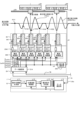
- FIG. 1 is a diagram showing an example of the configuration of a control device and a drive device according to a first embodiment
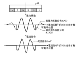
- FIG. 1 is a diagram for explaining a problem in the first embodiment
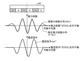
- FIG. 13 is a diagram for explaining a corrected thrust coefficient distribution used in the current command generating unit of the first embodiment
- FIG. 5 is a diagram for explaining the effect when a current command is generated using the corrected thrust coefficient distribution shown in FIG. 4 .
- FIG. 1 is a diagram showing a configuration example of a control device according to a first modification of the first embodiment
- FIG. 13 is a diagram showing a configuration example of a control device according to a second modification of the first embodiment
- FIG. 1 is a diagram for explaining a problem in the second embodiment.
- FIG. 13 is a diagram for explaining the operation of the control device according to the second embodiment;
- FIG. 10 is a diagram for explaining the problem in the third embodiment.
- FIG. 13 is a diagram for explaining a corrected thrust coefficient distribution used in a current command generating unit according to a third embodiment;
- FIG. 13 is a diagram for explaining the operation of the control device according to the fourth embodiment;
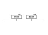
- FIG. 1 is a block diagram showing an example of a hardware configuration for implementing the functions of a control device and a drive device according to the first to fourth embodiments.
- FIG. 11 is a block diagram showing another example of a hardware configuration for implementing the functions of the control device and the drive device according to the first to fourth embodiments.
- FIG. 1 is a diagram showing an example of the configuration of a transport system 10 according to the first embodiment.
- the transport system 10 according to the first embodiment includes a control device 1, drive devices 2A, 2B, 2C, 2D, 2E, 2F, 2G, and 2H (hereinafter referred to as "2A to 2H" as appropriate, and the other reference characters are written similarly), coil units 3A to 3H, movers 4A to 4C, and scale heads 5A to 5C.
- the transport system 10 according to the first embodiment includes linear scales 6A and 6B.
- the drive devices 2C to 2H also include linear scales.
- the multiple driving devices 2 are connected to each other.
- the multiple driving devices 2 are connected to each other to form a conveying path 8 along which the mover 4 moves.
- the multiple driving devices 2 apply current to the coil unit 3 to generate thrust in the mover 4, causing the mover 4 to move.
- Drivers 2A, 2B, 2E, and 2F are linear drive units 2 that form a linear path.
- Drive units 2C, 2D, 2G, and 2H are curved drive units 2 that form a curved path, and change the direction of travel of the mover 4.
- the transport path 8 may not have linear drive units 2, and may consist only of curved drive units 2. In other words, the overall shape of the transport path 8 is arbitrary.
- the conveying system 10 is a moving magnet type linear motor.
- the mover 4 moves along a guide rail (not shown) provided on the side of the conveying path 8.
- the mover 4 has a permanent magnet (not shown) and is attached to the side of the conveying path 8.
- the mover 4 also has a guide roller (not shown) that moves on the guide rail by rotating.
- the mover 4 moves on the side of the conveying path 8 and stops on the side of the conveying path 8.
- the guide roller may be provided on the upper surface of the conveying path 8.
- each mover 4 is either clockwise in FIG. 1 or counterclockwise in FIG. 1.
- the clockwise direction of travel in FIG. 1 is the forward direction.
- the counterclockwise direction of travel in FIG. 1 is the reverse direction.
- Arrow 17A indicates the forward direction
- arrow 17B indicates the reverse direction.
- the conveying system 10 includes eight driving devices 2 and three movers 4.
- the number of driving devices 2 included in the conveying system 10 is arbitrary. That is, the number of driving devices 2 that configure the conveying path 8 is arbitrary, and the number of movers 4 that move on the conveying path 8 is also arbitrary. In addition, the number of movers 4 that move on the conveying path 8 may be one.
- the control device 1 is connected to each of the driving devices 2 via a data communication line 7.
- the control device 1 controls each of the multiple driving devices 2.
- the data communication line 7 is composed of a communication line that connects the control device 1 to a driving device 2 that is one of the multiple driving devices 2, and a communication line that connects adjacent driving devices 2 to each other. That is, the conveying system 10 is configured such that the control device 1 is connected to each of the driving devices 2 by a daisy chain connection. Note that the connection between the control device 1 and each of the driving devices 2 is not limited to a daisy chain connection.
- the connection between the control device 1 and each of the driving devices 2 may be a star connection in which each of the driving devices 2 is connected to the control device 1 via a communication hub.
- the conveying system 10 may be configured to include multiple data communication lines 7, and the control device 1 and each of the driving devices 2 may be directly connected by the data communication lines 7.
- the data communication line 7 may not be a physical communication line, but may be a communication path capable of wireless communication.
- the mover 4A is equipped with a permanent magnet 40.
- the permanent magnet 40 equipped to the mover 4A is a permanent magnet that contributes to driving the mover 4A.
- drive units 2A, 2B, 2E, and 2F are all linear drive units 2.
- drive units 2C, 2D, 2G, and 2H are curved drive units 2.
- the configuration of the curved drive unit 2 is the same as that of the linear drive unit 2, except that the arrangement of the coils 9 is different compared to the linear drive unit 2. Therefore, the following explanation will focus on drive unit 2A, which is a linear drive unit 2. The contents explained below are not limited to the linear drive unit 2.
- the five coils 9A in the coil unit 3A are labeled 9A1 to 9A5, and the five current control units 22A in the drive unit 20A are labeled 22A1 to 22A5.
- the five coils 9A labeled 9A1 to 9A5 are coils arranged in a range that is affected by the magnetic field emitted from the permanent magnet 40 provided in the mover 4A, and are coils that contribute to the drive of the mover 4A.
- the five current control units 22A labeled 22A1 to 22A5 are current control units connected to the coils 9A labeled 9A1 to 9A5.
- the coils 9A that are far from the mover 4A do not contribute significantly to the drive of the mover 4A.
- the coils 9A1 to 9A5 are described as the coils that contribute to the drive of the mover 4A.
- the coils 9A1 to 9A5 are supplied with driving current by the current control units 22A1 to 22A5, which are connected one-to-one to each other.
- the number of coils 9 that contribute to driving one mover 4 is determined by the number of coils 9 arranged in an area that is affected by the size of the permanent magnet 40 of the mover 4 and the strength of the magnetic field.
- the number of coils 9A that drive one mover 4A described here is an example, and is not limited to this example. In other words, the number of coils 9A that contribute to driving one mover 4A may be other than five.
- a scale head 5A is attached to the mover 4A.
- the scale head 5A moves on the linear scale 6A together with the mover 4A.
- the linear scale 6A detects the position information of the mover 4A and transmits it to the detector communication unit 24A of the drive device 2.
- the linear scale 6 detects a motion detection value yA such as the position and speed of the mover 4A from the position of the scale head 5 connected to the mover 4A, and transmits the detected motion detection value yA to the detector communication unit 24A.
- the scale head 5A can be composed of, for example, a permanent magnet for position detection, and the linear scale 6A can be composed of a sensor element that detects the magnetic field of the position detection magnet.
- the control device 1 includes a motion target value generating unit 11, a position and speed control unit 12, a current command generating unit 13, and a data communication unit 14.
- the motion target value generating unit 11 and the position and speed control unit 12 constitute a thrust command generating unit 15.
- the data communication unit 14 and data communication unit 21A are connected by communication line 7A, and the data communication unit 21A and data communication unit 21B are connected by communication line 7B.
- This connection is the daisy chain connection described above, and the communication data TxRx sent and received between the data communication unit 14 and data communication unit 21A includes not only information about the drive unit 2A, but also information about the drive units 2B to 2H.
- the data communication unit 21A of the drive unit 2A transmits the communication data TxRx received from the data communication unit 14 to the data communication unit 21B of the drive unit 2B.
- the data communication unit 21B similarly transmits the received communication data TxRx to the drive unit 2C, which is not shown in FIG. 2 below.
- the thrust command generating unit 15 generates a thrust command ⁇ ref, which is a command value of the thrust to be generated in the mover 4, based on the motion target value yref, which is a target value of the time series motion generated by the motion target value generating unit 11, and the motion detection value y, which indicates the motion position or motion speed of the mover 4.
- the position and speed control unit 12 generates the thrust command ⁇ ref so that the motion detection value y follows the motion target value yref.
- the motion target value yref includes motion target values for all movers 4A to 4C present in the transport system 10.
- the thrust command ⁇ ref is generated for each mover 4 and includes thrust commands for all movers 4A to 4C.
- the motion target value yref is configured to be generated inside the control device 1 in FIG. 2, this is not a limitation.
- the motion target value yref may be configured to be input to the control device 1 from outside.
- the current command generating unit 13 generates a current target value, which is a target value of the drive current to be applied to the multiple coils 9, as a current command Iref based on the thrust command ⁇ ref and the motion detection value y indicating the motion position or motion speed of the mover 4. A specific method of generating the current command Iref will be described later. Information related to the generated current command Iref is transmitted to the data communication unit 21A by the data communication unit 14.
- the data communication unit 21A of the drive unit 2A extracts current commands IrefA1 to IrefA5, which are current commands for the drive unit 2A, from the communication data TxRx transmitted from the data communication unit 14, and outputs the extracted current commands IrefA1 to IrefA5 to the current control units 22A1 to 22A5. It goes without saying that the communication data TxRx transmitted from the data communication unit 14 includes the current commands Iref for the drive units 2B to 2H.
- Current detectors 23A1-23A5 detect currents IA1-IA5 flowing through coils 9A1-9A5.
- Current control units 22A1-22A5 obtain current commands IrefA1-IrefA5 from data communication unit 21A, obtain operation detection value yA from detector communication unit 24A, and obtain detection values of currents IA1-IA5 from current detectors 23A1-23A5.
- Current control units 22A1-22A5 control currents IA1-IA5, which are drive currents provided to coils 9A1-9A5, so that the detection values of currents IA1-IA5 follow current commands IrefA1-IrefA5. Any method may be used to control currents IA1-IA5.
- Fig. 3 is a diagram for explaining the problem in the first embodiment.
- Fig. 4 is a diagram for explaining the corrected thrust coefficient distribution used in the current command generating unit 13 in the first embodiment.
- Fig. 5 is a diagram for explaining the effect when the current command Iref is generated using the corrected thrust coefficient distribution shown in Fig. 4.
- Figs. 3 and 5 are diagrams of the control device 1, driving unit 2A, coil unit 3A, mover 4A, scale head 5A, and linear scale 6A extracted from Fig. 2, and components that are the same or equivalent to those in Fig. 2 are indicated with the same reference numerals. Note that in the following description, parts that overlap with the above content will be omitted as appropriate.
- the current command generating unit 13 generates a current command IrefA based on the thrust command ⁇ ref and the motion detection value y of the mover 4. Specifically, the current command generating unit 13 calculates current commands IrefA1 to IrefA5, which are target values of the drive current to be applied to the coils 9A1 to 9A5, using the following formula (1). Note that the current command generating unit 13 calculates the current command Iref for each of the coils 9 of each coil unit 3 included in the transport system 10, but for convenience, the calculation of the five current commands IrefA1 to IrefA5 will be explained here.
- KA1 to KA5 are coefficients that represent the magnitude of thrust generated in response to currents IA1 to IA5 flowing through coils 9A1 to 9A5. In this paper, these coefficients are called "thrust coefficients.”
- FIG. 3 shows the waveform of the actual thrust coefficient distribution KA(x).
- the actual thrust coefficient distribution KA(x) is a waveform that shows the relationship between the mover position, which indicates the distance from the center position of the mover 4, and the thrust coefficient.
- the horizontal axis of the graph showing the waveform of the actual thrust coefficient distribution KA(x) indicates the mover position and is the axis that coincides with the thrust coefficient "0 (zero)".
- the thrust coefficients KA1 to KA5 in the above formula (1) can be found from the actual thrust coefficient distribution KA(x) shown in FIG. 3.
- the actual thrust coefficient distribution KA(x) is the actual thrust characteristic determined by the characteristics of the coil 9 and the mover 4.
- the characteristics of the coil 9 for determining the actual thrust characteristic are the number of windings of the coil 9, the radius of the coil winding, etc., and the characteristics of the mover 4 are the magnetic flux and magnetic pole pitch of the permanent magnet 40 provided in the mover 4.
- the thrust coefficients KA1 to KA5 in the actual thrust coefficient distribution KA(x) have the same value as the induced voltage coefficient that represents the relationship between the mover position and the induced voltage generated in coils 9A1 to 9A5 when the mover 4 moves. For this reason, this paper uses the actual thrust coefficient distribution KA(x) created using the induced voltage generated in coils 9A1 to 9A5 when the mover 4 moves.
- a current command IrefA of 0 [A] is generated.
- the current command IrefA of 0 [A] is input to the current control unit 22A via the data communication units 14, 21A.
- the current control unit 22A controls the current flowing through the coil 9A to 0 [A]. As a result, no drive current flows through the coil 9A to which the current command IrefA of 0 [A] is commanded.
- a current command IrefA other than 0 [A] is generated.
- the current command IrefA other than 0 [A] is input to the current control unit 22A via the data communication units 14, 21A.
- the current control unit 22A controls the current flowing through the coil 9A to a value other than 0 [A].
- a drive current flows through the coil 9A to which the current command IrefA other than 0 [A] is commanded.
- the corrected thrust coefficient distribution K'A(x) shown in FIG. 4 is used instead of the actual thrust coefficient distribution KA(x) shown in FIG. 3.
- the actual thrust coefficient distribution KA(x) shown in FIG. 3 is shown by a dashed line
- the corrected thrust coefficient distribution K'A(x) is shown by a solid line.
- FIG. 5 shows an example of the configuration of a control device 1' that uses the corrected thrust coefficient distribution K'A(x).
- the current command generation unit 13 shown in FIG. 3 is replaced with a current command generation unit 13'.
- FIG. 5 shows an example of the configuration of a control device 1' that uses the corrected thrust coefficient distribution K'A(x).
- the current command IrefA (IrefA1 to IrefA5) input to the current control unit 22A is set to the current command Iref'A (Iref'A1 to Iref'A5).
- the current command generation unit 13' generates the current command Iref'A, which is the current target value, using a part of the actual thrust characteristic determined by the characteristics of the coil 9 and the mover 4.
- parts that are the same as or equivalent to those in Figure 3 are denoted with the same reference numerals, and duplicate explanations are omitted where appropriate.
- K'A1 to K'A5 are thrust coefficients calculated from the corrected thrust coefficient distribution K'A(x).
- the corrected thrust coefficient distribution K'A(x) is a waveform that represents a corrected thrust characteristic created using a portion of the actual thrust coefficient distribution KA(x), which is the actual thrust characteristic determined by the characteristics of the multiple coils 9 and the mover 4.
- the corrected thrust coefficient distribution K'A(x) is created by cutting out a portion of the actual thrust coefficient distribution KA(x), which is determined by the characteristics of the coils 9A1 to 9A5 and the mover 4A.
- the value of the thrust coefficient K'A1 corresponding to coil 9A1 and the value of the thrust coefficient K'A5 corresponding to coil 9A5 are set to "0". Therefore, when the current command Iref'A1, which is the target value of the drive current given to coil 9A1, and the current command Iref'A5, which is the target value of the drive current given to coil 9A5, are calculated using equation (2), they become current commands of 0 [A]. As a result, the number of coils 9A through which the drive current flows becomes three from five, reducing the number of coils 9A through which the drive current flows.
- control device 1' As described above, by using the control device 1' according to the first embodiment, it is possible to reduce the number of coils through which the drive current flows, without connecting switches to multiple coils 9 as in Patent Document 1.
- the motion target value generating unit 11'' when the motion target value yref generated by the motion target value generating unit 11'' can be regarded as a thrust command ⁇ ref, the motion target value generating unit 11 can be configured as a thrust command generating unit 15'' as shown in FIG. 6, and the thrust command ⁇ ref output from the thrust command generating unit 15'' can be input to the current command generating unit 13''.
- the current command generating unit 13'' generates a current command Iref'' using the thrust command ⁇ ref and outputs it to the data communication unit 14.
- the current control unit 22A receives the current commands Iref''A (Iref''A1 to Iref''A5) via the data communication units 14 and 21A.
- the current control unit 22A controls the currents IA1 to IA5, which are the drive currents provided to the coils 9A1 to 9A5, so that the detection values of the currents IA1 to IA5 follow Iref''A1 to Iref''A5.
- FIG. 7 is a diagram showing an example of the configuration of a control device 1''' according to a second modified example of embodiment 1.
- the thrust command generating unit 15 shown in FIG. 5 is replaced with a thrust command generating unit 15'''.
- the position and speed control unit 12 and the current command generating unit 13' shown in FIG. 5 are moved to the drive device 2A in FIG. 7 and configured as a position and speed control unit 25A''' and a current command generating unit 26A'''.
- the operation target value generating unit 11 shown in FIG. 5 is replaced with an operation target value generating unit 11'''. That is, in FIG.
- the operation target value generating unit 11''' and the position and speed control unit 25A''', which are components of the thrust command generating unit 15''', are separately arranged in the control device 1'' and the drive device 2A'''', respectively.
- the data communication unit 14 shown in FIG. 5 is replaced with a data communication unit 14'''
- the data communication unit 21A shown in FIG. 5 is replaced with a data communication unit 21A'''.
- parts that are the same as or equivalent to those in FIG. 5 are denoted with the same reference numerals, and duplicate explanations will be omitted as appropriate.
- the motion target value yref generated by the motion target value generating unit 11''' is output to the data communication unit 14 and transmitted to the drive unit 2A.
- the position and speed control unit 25A''' receives information on the motion target value yref via the data communication unit 21A'''.
- the position and speed control unit 25A''' generates a thrust command ⁇ ref so that the motion detection value y follows the motion target value yref, and outputs it to the current command generating unit 26A'''.
- the current command generating unit 26A''' generates current commands Iref''A (Iref''A1 to Iref''A5) based on the thrust command ⁇ ref and the motion detection value yA of the mover 4A, and outputs it to the current control unit 22A.
- the current control unit 22A controls the currents IA1 to IA5, which are the drive currents provided to the coils 9A1 to 9A5, so that the detected values of the currents IA1 to IA5 follow the current commands Iref''A1 to Iref''A5.
- the conveying system is a conveying system including a mover and a conveying path along which the mover moves.
- the conveying system includes a driving unit that supplies a driving current to a plurality of coils arranged along the conveying path, and a thrust command generating unit that generates a thrust command, which is a command value of a thrust to be generated in the mover, based on an operation target value that is a target value of a time series operation input from the outside or generated internally.
- the conveying system also includes a current command generating unit that generates a current target value, which is a target value of a driving current to be applied to the plurality of coils so that the thrust generated by the mover follows the thrust command, as a current command.
- the current command generating unit generates a current target value to be applied to the plurality of coils by using a part of the actual thrust characteristics determined by the characteristics of the plurality of coils and the mover so as to reduce the number of coils through which the driving current flows.
- the conveying system configured in this way, it is possible to reduce the number of coils through which the driving current flows without connecting a switch to the plurality of coils as in Patent Document 1. This makes it possible to obtain a conveying system that can simplify the circuit configuration and enable control by simple processing.
- the control device is a control device configured to be applicable to a conveying system including a mover, a conveying path along which the mover moves, and a driving device that supplies a driving current to a plurality of coils arranged along the conveying path.
- the control device includes a thrust command generating unit that generates a thrust command, which is a command value of a thrust to be generated in the mover, based on an operation target value that is a target value of a time-series operation input from the outside or generated internally.
- the control device also includes a current command generating unit that generates a current target value, which is a target value of a driving current to be applied to the plurality of coils so that the thrust generated by the mover follows the thrust command, as a current command.
- the current command generating unit generates a current target value to be applied to the plurality of coils by using a part of the actual thrust characteristics determined by the characteristics of the plurality of coils and the mover so as to reduce the number of coils through which the driving current flows. According to the control device configured in this way, it is possible to reduce the number of coils through which the driving current flows without connecting a switch to the plurality of coils as in Patent Document 1. This makes it possible to obtain a control device that can simplify the circuit configuration and enable control by simple processing.
- Embodiment 2 In the second embodiment, a transport system and a control device that can solve the problem in the first embodiment and also solve another problem will be described.
- Fig. 8 is a diagram for explaining the problem in the second embodiment. In Fig. 8, the same components and elements as those in Fig. 3 are denoted by the same reference numerals. In the following description, parts that overlap with the above content will be omitted as appropriate.
- Figure 8 shows a situation where multiple movers 4 are adjacent to each other on a linear scale 6A, with the adjacent mover 4B shown along with the mover 4A. Also in Figure 8, the waveform of the actual thrust coefficient distribution KA(x) using the characteristics of the mover 4A is shown by a solid line, and the waveform of the actual thrust coefficient distribution KB(x) using the characteristics of the mover 4B is shown by a dashed line.
- the actual thrust coefficient distribution KA(x) is used when generating the current command Iref for the coil 9 that passes a drive current to drive the mover 4A, and the actual thrust coefficient distribution KB(x) is used when generating the current command Iref for the coil 9 that passes a drive current to drive the mover 4B.
- the coils 9 that drive these movers 4A and 4B are also adjacent.
- the multiple coils 9A that drive mover 4A (the "first coil group” described below) and the multiple coils 9B that drive mover 4B (the “second coil group” described below) are adjacent.
- adjacent refers to a situation in which, as shown in Figure 8, the right-hand coils 9A4 and 9A5 of the coil group 9A1 to 9A5 that drives mover 4A, one of the movers, overlap with the left-hand coils 9B1 and 9B2 of the coil group 9B1 to 9B5 (coils 9B3 to 9B5 are not shown) that drives mover 4B, the other mover.
- the thrust coefficients KA4, KA5 used when generating the current commands IrefA4, A5 for the coils 9A4, 9A5 when driving the mover 4A overlap with the thrust coefficients KB1, KB2 used when generating the current commands IrefB1, B2 for the coils 9B1, 9B2 when driving the mover 4B, so this situation can be considered adjacent.
- any one of the multiple movers 4 may be referred to as the "first mover,” and a coil group consisting of multiple coils 9 that drive the first mover may be referred to as the "first coil group.”
- the mover 4 adjacent to the first mover may be referred to as the "second mover,” and a coil group consisting of multiple coils 9 that drive the second mover may be referred to as the "second coil group.”
- the current command IrefA5 for coil 9A4 and the current command IrefB2 for the same coil, coil 9B1 can be expressed as the following equations (3) and (4) using the above equation (1).
- IrefA5 KA5/(KA1 ⁇ 2+KA2 ⁇ 2+KA3 ⁇ 2+KA4 ⁇ 2+KA5 ⁇ 2) ⁇ refA ...Equation (3)
- IrefB2 KB2/(KB1 ⁇ 2+KB2 ⁇ 2+KB3 ⁇ 2+KB4 ⁇ 2+KB5 ⁇ 2) ⁇ refB ...Equation (4)
- ⁇ refA is a thrust command for the mover 4A
- ⁇ refB is a thrust command for the mover 4B. Because the thrust commands ⁇ refA and ⁇ refB change over time, the current command IrefA5 for the overlapping coil 9A5 and the current command IrefB2 for the overlapping coil 9B2 do not always match. If these current commands IrefA5 and B2 do not match, when the current command IrefA5 calculated from formula (3) is input to the current control unit 22A5 that passes the drive current to the coil 9A5 (9B2), the thrust generated in the mover 4B will not match the thrust command ⁇ refB.
- control device 1' described in the first embodiment is used, and the corrected thrust coefficient distribution K'A(x) proposed in the first embodiment is used to drive the mover 4.
- Figure 9 is a diagram used to explain the operation of the control device 1' according to the second embodiment.
- components that are the same as or equivalent to those in Figure 5 are denoted by the same reference numerals. Note that in the following description, parts that overlap with the above content will be omitted as appropriate.
- the waveform of the corrected thrust coefficient distribution K'A(x) is shown by a solid line, and the waveform of the corrected thrust coefficient distribution K'B(x) is shown by a dashed line.
- the corrected thrust coefficient distribution K'A(x) is used when generating a current command Iref for the coil 9 that passes a drive current to drive the mover 4A
- the corrected thrust coefficient distribution K'B(x) is used when generating a current command Iref for the coil 9 that passes a drive current to drive the mover 4B.
- FIG. 9 describes a case where two movers 4A and 4B are adjacent, this is not limiting. The same explanation can be given for cases where movers 4B and 4C are adjacent, or where movers 4A and 4C are adjacent. Also, while FIG. 9 describes a case where two movers 4A and 4B are adjacent, the same explanation can be given for cases where three or more movers 4 are adjacent.
- the current command Iref' can always be calculated using equation (2) and the corrected thrust coefficient distributions K'A(x) and K'B(x), regardless of the adjacent state of multiple movers 4. Therefore, by using the method of the second embodiment, the current command Iref' can be calculated using only simple arithmetic operations, and complex calculations such as simultaneous equations are not required. This has the effect of reducing the amount of calculation and the computational load.
- the current command Iref' can be calculated using the same formula (2) for all of the multiple movers 4, so the corrected thrust coefficient distribution K'(x) can be set to the same value for all of the multiple movers 4. This has the effect of enabling the same control for all movers 4, since the thrust command generated for all movers 4 is the same value.
- the current command generation unit generates a current target value to be given to the coils of the first coil group using a portion of the actual thrust characteristics determined by the coils of the first coil group and the characteristics of the first movable element driven by the first coil group. Also, the current command generation unit generates a current target value to be given to the coils of the second coil group using a portion of the actual thrust characteristics determined by the coils of the second coil group and the characteristics of the second movable element driven by the second coil group.
- the first coil group referred to here is a coil group consisting of multiple coils that drive the first movable element
- the second coil group is a coil group consisting of multiple coils that drive the second movable element and is adjacent to the first coil group.
- the operation and effects of using the control device 1' and drive device 2A shown in FIG. 5 are described, but the effects of the second embodiment can also be obtained when using the control device 1'' and drive device 2A shown in FIG. 6. Also, the effects of the second embodiment can also be obtained when using the control device 1''' and drive device 2A''' shown in FIG. 7.
- Embodiment 3 a method for generating a corrected thrust coefficient distribution K''A(x) used when the transport system 10 according to the third embodiment calculates the current command Iref'' will be described.
- the corrected thrust coefficient distribution K'A(x) described in the first embodiment can be a waveform that is a portion of the actual thrust coefficient distribution KA(x), so it can be said that there is a high degree of freedom in its creation.
- an inappropriate corrected thrust coefficient distribution K'A(x) is created, there is a problem that the mover 4 cannot be controlled with high precision.
- a method of generating a corrected thrust coefficient distribution K'''A(x) that can address this problem is proposed.
- FIG. 10 is a diagram used to explain the problem in the third embodiment.
- the actual thrust coefficient distribution KA(x) shown in FIG. 3 is shown by a dashed line
- the corrected thrust coefficient distribution K′′A(x) generated using this actual thrust coefficient distribution KA(x) is shown by a solid line.
- the corrected thrust coefficient distribution K′′A(x) shown in FIG. 10 is an example of an inappropriate corrected thrust coefficient distribution.
- the horizontal axis of the graph showing the waveform of the current command Iref′′ indicates the position of the mover and coincides with the current command "0 (zero)". The same applies to the following figures.
- the corrected thrust coefficient distribution K''A(x) shown in FIG. 10 is created using the actual thrust coefficient distribution KA(x), but the thrust coefficient value changes discontinuously and abruptly. Therefore, the current command Iref'' generated using this corrected thrust coefficient distribution K''A(x) also changes discontinuously and abruptly. On the other hand, even if such a current command Iref' is given to the coil 9, it is difficult to abruptly change the current IA flowing through the coil 9 due to the inductance of the coil 9. This causes a large error between the current IA flowing through the coil 9 and the current command Iref'', making it difficult to control the multiple movers 4 with high precision.
- FIG. 11 is a diagram used to explain the corrected thrust coefficient distribution used in the current command generating unit 13' of the third embodiment.
- the explanation here uses the control device 1' and drive device 2A shown in FIG. 5 or FIG. 10.
- the actual thrust coefficient distribution KA(x) shown in Figure 3 is shown by a dashed line
- the corrected thrust coefficient distribution K'''A(x) generated using this actual thrust coefficient distribution KA(x) is shown by a solid line.
- the corrected thrust coefficient distribution K'''A(x) shown in Figure 11 is an example of an appropriate corrected thrust coefficient distribution.
- Figure 11 shows an example in which the thrust coefficient values are cut out so that they are continuous when a portion of the actual thrust coefficient distribution KA(x) is used to create the distribution.
- Continuous here means that the thrust coefficient values in the newly created modified thrust coefficient distribution K'''A(x) do not deviate from the values of the actual thrust characteristics defined by the actual thrust coefficient distribution KA(x).
- the thrust coefficient value in the modified thrust coefficient distribution K'''A(x) is 0.
- the thrust coefficient value in the modified thrust coefficient distribution K'''A(x) is set to 0 starting from the point where the actual thrust coefficient distribution KA(x) crosses zero. Therefore, the current command Iref''' generated using this modified thrust coefficient distribution K'''A(x) changes continuously and smoothly, unlike the case of Figure 10. As a result, even if the current flowing through the coil 9 is controlled using the current command Iref''' generated using the corrected thrust coefficient distribution K''A(x), the error between the current IA flowing through the coil 9 and the current command Iref'' can be reduced, making it possible to control multiple movers 4 with high precision.
- the current command generation unit generates a current command using a thrust coefficient whose value does not deviate from the value of the actual thrust characteristic determined by the characteristics of the multiple coils and movers. This makes it possible to reduce the error between the current flowing through the coils and the current command, and to control the multiple movers with high precision.
- the operation and effects of using the control device 1' and drive device 2A shown in FIG. 5 or FIG. 10 are described, but the operation may be performed using the control device 1'' and drive device 2A shown in FIG. 6, or the operation may be performed using the control device 1''' and drive device 2A'' shown in FIG. 7. In this way, it is possible to enjoy the effects obtained in the first and second embodiments, as well as the effects obtained in the third embodiment.
- Embodiment 4 In the first embodiment, a method for generating the current command Iref' using the corrected thrust coefficient distribution K'A(x) created using part of the actual thrust characteristics determined by the characteristics of a plurality of coils and a mover, and further using the above formula (2) has been described. In the fourth embodiment, a method for generating the current command Iref'''' using a calculation formula different from that of the first embodiment will be described.
- FIG. 12 is a diagram for explaining the operation of the control device 1'''' according to embodiment 4.
- the current command generating unit 13' shown in FIG. 5 is replaced with a current command generating unit 13''''.
- FIG. 12 also shows the same actual thrust coefficient distribution KA(x) as FIG. 3.
- FIG. 12 also shows the virtual conductance distribution CA(x).
- the horizontal axis of the graph showing the waveform of the virtual conductance CA(x) indicates the position of the mover and is the axis that coincides with the virtual conductance "0 (zero)".
- FIG. 12 also shows the waveform of the current command obtained from the product of the actual thrust coefficient distribution KA(x) and the virtual conductance distribution CA(x).
- This waveform of the current command is a waveform that represents the relationship between the mover position, which represents the distance from the center position of the mover 4, and the current command.
- the virtual conductance distribution CA(x) is a waveform that represents the relationship between the mover position, which represents the distance from the center position of the mover 4, and the virtual conductance. Additionally, the virtual conductance is a correction coefficient that changes depending on the position of the mover.
- parts that are the same as or equivalent to those in FIG. 5 are denoted by the same reference numerals, and duplicated explanations are omitted as appropriate.
- the current command generating unit 13''''' generates a current target value, which is a target value of the drive current to be applied to the multiple coils 9, as a current command Iref'''', based on the thrust command ⁇ ref and the motion detection value y indicating the motion position or motion speed of the mover 4. Specifically, the current command generating unit 13''''' calculates current commands Iref''''A1 to Iref''''A5, which are target values of the drive current to be applied to the coils 9A1 to 9A5, using the following formula (5).
- the current command generating unit 13''''' calculates the current command Iref'''' for each of the coils 9 of each coil unit 3 provided in the transport system 10, but for convenience, the calculation of five current commands Iref''''A1 to Iref''''A5 will be explained here.
- CA1 to CA5 are virtual conductances, and are coefficients introduced to adjust the value of the current command Iref''''A calculated by the current command generating unit 13''''.
- the virtual conductances CA1 to CA5 can be obtained from the virtual conductance distribution CA(x).
- the current commands Iref''''A1 to Iref''''A5 calculated by equation (5) can set the thrust ⁇ generated in the mover 4 to the thrust command ⁇ ref, which is the target value of the thrust ⁇ , regardless of the values of the virtual conductances CA1 to CA5. In other words, even if virtual conductances CA1 to CA5 are introduced, the thrust ⁇ generated in the mover 4 will not deviate from the thrust command ⁇ ref.
- a current command Iref''''A that is not 0 [A] is generated.
- the current command Iref''''A that is not 0 [A] is input to the current control unit 22A via the data communication units 14, 21A.
- the current control unit 22A controls the current flowing through the coil 9A to a value other than 0 [A]. As a result, a drive current flows through the coil 9A to which the current command Iref''''A that is not 0 [A] is commanded.
- the number of coils through which the drive current flows can be freely changed by adjusting the values of the virtual conductances CA1 to CA5 multiplied by the thrust coefficients KA1 to KA5, making it possible to reduce the number of coils through which the drive current flows without connecting switches to the multiple coils 9.
- generating a current command Iref''''A to reduce the number of coils through which the drive current flows using the virtual conductances CA1 to CA5 multiplied by the thrust coefficients KA1 to KA5 generates a current target value to be given to the multiple coils 9 using a portion of the actual thrust characteristics determined by the characteristics of the multiple coils 9 and the mover 4.
- the current command generation unit generates a current target value to be given to the multiple coils using a corrected thrust characteristic created using the actual thrust characteristic determined by the characteristics of the multiple coils and the mover, and a correction coefficient that changes depending on the position of the mover.
- the current command generation unit generates a current target value to be given to the multiple coils using a portion of the actual thrust characteristic determined by the characteristics of the multiple coils and the mover. This makes it possible to reduce the error between the current flowing through the coil and the current command, and to control the multiple movers with high precision.
- control device 1 and drive device 2A shown in FIG. 3 the operation and effects of using the control device 1 and drive device 2A shown in FIG. 3 have been described, but the operation may be performed using the control device 1' and drive device 2A shown in FIGS. 5 and 9, the control device 1'' and drive device 2A shown in FIG. 6, or the control device 1''' and drive device 2A'' shown in FIG. 7.
- the control device 1' and drive device 2A shown in FIG. 5 may also be operated using the corrected thrust coefficient distribution K''A(x) described in the third embodiment. In this way, it is possible to enjoy the effects obtained in the first to third embodiments and the effects obtained in the fourth embodiment.
- Fig. 13 is a block diagram showing an example of a hardware configuration for realizing the functions of the control devices 1-1'''' and drive devices 2A-2H in embodiments 1 to 4.
- Fig. 14 is a block diagram showing another example of a hardware configuration for realizing the functions of the control devices 1-1'''' and drive devices 2A-2H in embodiments 1 to 4.
- the configuration can include a processor 300 that performs calculations, a memory 302 that stores programs read by the processor 300, and a communication circuit 304 that transmits and receives signals, as shown in FIG. 13.
- Processor 300 is an example of a computing means.
- Processor 300 may be a computing means called a microprocessor, a microcomputer, a CPU (Central Processing Unit), or a DSP (Digital Signal Processor).
- Examples of memory 302 include non-volatile or volatile semiconductor memory such as RAM (Random Access Memory), ROM (Read Only Memory), flash memory, EPROM (Erasable Programmable ROM), and EEPROM (registered trademark) (Electrically EPROM), magnetic disks, flexible disks, optical disks, compact disks, mini disks, and DVDs (Digital Versatile Discs).
- Memory 302 stores programs that execute the functions of control devices 1-1'''' and drive devices 2A-2H in embodiments 1 to 4.
- Processor 300 receives and transmits necessary information via communication circuit 304, executes the programs stored in memory 302, and refers to the tables stored in memory 302, thereby performing the above-mentioned processing.
- the results of calculations by processor 300 can be stored in memory 302.
- the processing circuit 303 shown in FIG. 14 can be used.
- the processing circuit 303 can be a single circuit, a composite circuit, an ASIC (Application Specific Integrated Circuit), an FPGA (Field-Programmable Gate Array), or a combination of these.
- Information input to the processing circuit 303 and information output from the processing circuit 303 can be transmitted and received via the communication circuit 304.
- control devices 1-1'''' and the drive devices 2A-2H may be performed by the processing circuit 303, and the processing that is not performed by the processing circuit 303 may be performed by the processor 300 and memory 302.
Landscapes
- Engineering & Computer Science (AREA)
- Power Engineering (AREA)
- Control Of Linear Motors (AREA)
- Linear Motors (AREA)
Priority Applications (5)
| Application Number | Priority Date | Filing Date | Title |
|---|---|---|---|
| DE112023006274.9T DE112023006274T5 (de) | 2023-08-03 | 2023-08-03 | Fördersystem und Steuervorrichtung |
| PCT/JP2023/028460 WO2025027856A1 (ja) | 2023-08-03 | 2023-08-03 | 搬送システム及び制御装置 |
| KR1020257042936A KR102947930B1 (ko) | 2023-08-03 | 2023-08-03 | 반송 시스템 및 제어 장치 |
| CN202380100119.3A CN121464577A (zh) | 2023-08-03 | 2023-08-03 | 输送系统及控制装置 |
| JP2023574285A JP7515752B1 (ja) | 2023-08-03 | 2023-08-03 | 搬送システム及び制御装置 |
Applications Claiming Priority (1)
| Application Number | Priority Date | Filing Date | Title |
|---|---|---|---|
| PCT/JP2023/028460 WO2025027856A1 (ja) | 2023-08-03 | 2023-08-03 | 搬送システム及び制御装置 |
Publications (1)
| Publication Number | Publication Date |
|---|---|
| WO2025027856A1 true WO2025027856A1 (ja) | 2025-02-06 |
Family
ID=91810484
Family Applications (1)
| Application Number | Title | Priority Date | Filing Date |
|---|---|---|---|
| PCT/JP2023/028460 Pending WO2025027856A1 (ja) | 2023-08-03 | 2023-08-03 | 搬送システム及び制御装置 |
Country Status (5)
| Country | Link |
|---|---|
| JP (1) | JP7515752B1 (https=) |
| KR (1) | KR102947930B1 (https=) |
| CN (1) | CN121464577A (https=) |
| DE (1) | DE112023006274T5 (https=) |
| WO (1) | WO2025027856A1 (https=) |
Citations (2)
| Publication number | Priority date | Publication date | Assignee | Title |
|---|---|---|---|---|
| JPH0919178A (ja) * | 1995-06-27 | 1997-01-17 | Canon Inc | リニア・モータ装置 |
| JP2017079569A (ja) * | 2015-10-22 | 2017-04-27 | キヤノン株式会社 | 可動磁石型リニアモータ制御システム |
Family Cites Families (1)
| Publication number | Priority date | Publication date | Assignee | Title |
|---|---|---|---|---|
| JP7025256B2 (ja) | 2018-03-16 | 2022-02-24 | キヤノン株式会社 | ステージ装置、リソグラフィ装置、および物品の製造方法 |
-
2023
- 2023-08-03 KR KR1020257042936A patent/KR102947930B1/ko active Active
- 2023-08-03 CN CN202380100119.3A patent/CN121464577A/zh active Pending
- 2023-08-03 DE DE112023006274.9T patent/DE112023006274T5/de active Pending
- 2023-08-03 WO PCT/JP2023/028460 patent/WO2025027856A1/ja active Pending
- 2023-08-03 JP JP2023574285A patent/JP7515752B1/ja active Active
Patent Citations (2)
| Publication number | Priority date | Publication date | Assignee | Title |
|---|---|---|---|---|
| JPH0919178A (ja) * | 1995-06-27 | 1997-01-17 | Canon Inc | リニア・モータ装置 |
| JP2017079569A (ja) * | 2015-10-22 | 2017-04-27 | キヤノン株式会社 | 可動磁石型リニアモータ制御システム |
Also Published As
| Publication number | Publication date |
|---|---|
| DE112023006274T5 (de) | 2026-04-16 |
| KR20260011187A (ko) | 2026-01-22 |
| CN121464577A (zh) | 2026-02-03 |
| JP7515752B1 (ja) | 2024-07-12 |
| KR102947930B1 (ko) | 2026-04-03 |
| JPWO2025027856A1 (https=) | 2025-02-06 |
Similar Documents
| Publication | Publication Date | Title |
|---|---|---|
| JP6704705B2 (ja) | 可動磁石型リニアモータ制御システム及びその制御方法 | |
| CN101356714B (zh) | 传送工具、传送方法、和传送系统 | |
| CN109217768B (zh) | 长定子线性电动机和用于移动长定子线性电动机的运输单元的方法 | |
| JP7452952B2 (ja) | 移行位置における運搬ユニットを移行するための方法と長固定子リニアモータ | |
| JP2007500495A (ja) | 移動調整機能付きリニアモータ | |
| JP2007536178A5 (https=) | ||
| US20210261351A1 (en) | Independent Mover Transport System And Method Of Extending Range Of Operations In An Independent Mover Transport System | |
| CN103270694B (zh) | 电动机控制装置、电动机控制方法及控制程序 | |
| JP7515752B1 (ja) | 搬送システム及び制御装置 | |
| JP2018177002A (ja) | 無人搬送台車 | |
| Defoort et al. | Integral sliding mode control of an extended Heisenberg system | |
| JP7415085B1 (ja) | 搬送システム | |
| JP7682421B1 (ja) | 制御装置及び搬送システム | |
| TWI888770B (zh) | 馬達系統 | |
| WO2024029047A1 (ja) | 搬送システム | |
| JPWO2024100885A5 (https=) | ||
| CN119731100A (zh) | 货物传输系统,控制单元,构造套件,模拟程序产品和平面马达的主动构件的应用 | |
| JP7665874B1 (ja) | 搬送システム | |
| JP7721039B1 (ja) | 搬送システム | |
| JP5348107B2 (ja) | 搬送車 | |
| JP2004237384A (ja) | ロボットの動作制御方法 | |
| JPWO2025027856A5 (https=) | ||
| CN121626713A (zh) | 磁驱输送系统的动子运行驱动方法及相关设备 | |
| JPS63253413A (ja) | リニアモ−タ搬送台車 | |
| HK1237902B (zh) | 搬运机器人运行控制方法、装置及机器人 |
Legal Events
| Date | Code | Title | Description |
|---|---|---|---|
| WWE | Wipo information: entry into national phase |
Ref document number: 2023574285 Country of ref document: JP |
|
| 121 | Ep: the epo has been informed by wipo that ep was designated in this application |
Ref document number: 23947653 Country of ref document: EP Kind code of ref document: A1 |
|
| ENP | Entry into the national phase |
Ref document number: 1020257042936 Country of ref document: KR Free format text: ST27 STATUS EVENT CODE: A-0-1-A10-A15-NAP-PA0105 (AS PROVIDED BY THE NATIONAL OFFICE) |
|
| WWE | Wipo information: entry into national phase |
Ref document number: 1020257042936 Country of ref document: KR |
|
| WWE | Wipo information: entry into national phase |
Ref document number: 112023006274 Country of ref document: DE |
|
| WWP | Wipo information: published in national office |
Ref document number: 1020257042936 Country of ref document: KR |