WO2025018335A1 - 開閉体の開閉装置 - Google Patents
開閉体の開閉装置 Download PDFInfo
- Publication number
- WO2025018335A1 WO2025018335A1 PCT/JP2024/025480 JP2024025480W WO2025018335A1 WO 2025018335 A1 WO2025018335 A1 WO 2025018335A1 JP 2024025480 W JP2024025480 W JP 2024025480W WO 2025018335 A1 WO2025018335 A1 WO 2025018335A1
- Authority
- WO
- WIPO (PCT)
- Prior art keywords
- opening
- closing body
- locking member
- locking
- biasing
- Prior art date
- Legal status (The legal status is an assumption and is not a legal conclusion. Google has not performed a legal analysis and makes no representation as to the accuracy of the status listed.)
- Pending
Links
Images






Classifications
-
- B—PERFORMING OPERATIONS; TRANSPORTING
- B60—VEHICLES IN GENERAL
- B60K—ARRANGEMENT OR MOUNTING OF PROPULSION UNITS OR OF TRANSMISSIONS IN VEHICLES; ARRANGEMENT OR MOUNTING OF PLURAL DIVERSE PRIME-MOVERS IN VEHICLES; AUXILIARY DRIVES FOR VEHICLES; INSTRUMENTATION OR DASHBOARDS FOR VEHICLES; ARRANGEMENTS IN CONNECTION WITH COOLING, AIR INTAKE, GAS EXHAUST OR FUEL SUPPLY OF PROPULSION UNITS IN VEHICLES
- B60K15/00—Arrangement in connection with fuel supply of combustion engines or other fuel consuming energy converters, e.g. fuel cells; Mounting or construction of fuel tanks
- B60K15/03—Fuel tanks
- B60K15/04—Tank inlets
- B60K15/05—Inlet covers
-
- B—PERFORMING OPERATIONS; TRANSPORTING
- B60—VEHICLES IN GENERAL
- B60L—PROPULSION OF ELECTRICALLY-PROPELLED VEHICLES; SUPPLYING ELECTRIC POWER FOR AUXILIARY EQUIPMENT OF ELECTRICALLY-PROPELLED VEHICLES; ELECTRODYNAMIC BRAKE SYSTEMS FOR VEHICLES IN GENERAL; MAGNETIC SUSPENSION OR LEVITATION FOR VEHICLES; MONITORING OPERATING VARIABLES OF ELECTRICALLY-PROPELLED VEHICLES; ELECTRIC SAFETY DEVICES FOR ELECTRICALLY-PROPELLED VEHICLES
- B60L53/00—Methods of charging batteries, specially adapted for electric vehicles; Charging stations or on-board charging equipment therefor; Exchange of energy storage elements in electric vehicles
- B60L53/10—Methods of charging batteries, specially adapted for electric vehicles; Charging stations or on-board charging equipment therefor; Exchange of energy storage elements in electric vehicles characterised by the energy transfer between the charging station and the vehicle
- B60L53/14—Conductive energy transfer
-
- E—FIXED CONSTRUCTIONS
- E05—LOCKS; KEYS; WINDOW OR DOOR FITTINGS; SAFES
- E05B—LOCKS; ACCESSORIES THEREFOR; HANDCUFFS
- E05B83/00—Vehicle locks specially adapted for particular types of wing or vehicle
- E05B83/28—Locks for glove compartments, console boxes, fuel inlet covers or the like
- E05B83/34—Locks for glove compartments, console boxes, fuel inlet covers or the like for fuel inlet covers essentially flush with the vehicle surface
Definitions
- the present invention relates to an opening/closing device for an opening/closing body that opens and closes an opening of a fixed member having an opening into which an insert member is inserted.
- a charging gun power supply gun
- electricity is supplied from an electricity supply facility (such as a power supply station) to the electric vehicle's battery, causing the battery to be charged.
- Such a charging port is located inside a power supply opening formed in the vehicle body, and the power supply opening can be opened and closed by a lid. Furthermore, it is common for the charging port to have an opening for normal charging and an opening for quick charging. Furthermore, the opening for quick charging is often further covered by an openable and closable cover.
- Patent Document 1 describes a connection device for charging a vehicle battery device, which has a cover flap that is attached to an opening for quick charging so as to be able to open and close, a biasing member that biases the cover flap to a closed state, a latching means that holds the cover flap in an open state and releases the held state when a charging gun is inserted, and a spring member that biases the latching means to the latched position.
- connection device of Patent Document 1 two biasing members were required: a biasing member that biases the cover flap to the closed state, and a spring member that biases the latch means to the latched position, resulting in a large number of parts and a complex structure.
- the object of the present invention is therefore to provide an opening and closing device for an opening and closing body that can reduce the number of parts and simplify the structure.
- the present invention provides an opening/closing device for an opening/closing body that opens and closes an opening of a fixed member having an opening into which an insertion member is inserted, the opening/closing device comprising: a base member fixed to the fixed member; an opening/closing body that is rotatably attached to the base member via a first pivot support portion to open and close the opening and has an engaged portion; a locking member that is rotatably attached to the base member via a second pivot support portion and has an abutment portion with which the insertion member abuts and an engagement portion that engages with the engaged portion to hold the opening/closing body in an open state when the opening/closing body is opened relative to the opening; and a biasing member that has a winding portion, a first arm portion extending from one end of the winding portion, and a second arm portion extending from the other end of the winding portion, the opening/closing body having a first engaging portion, and the first arm portion
- the opening/closing body is biased in a direction to close the opening
- the locking member has a second locking portion
- the second arm portion is engaged with the second locking portion
- the locking member is biased in a direction opposite to the biasing direction of the opening/closing body and such that the abutting portion enters the insertion path along the insertion direction of the insertion member into the opening
- a stopper portion is provided between the base member and the locking member and/or between the opening/closing body and the locking member to prevent the locking member from coming off the base member, and when the insertion member is inserted into the opening and abuts against the abutting portion, the locking member rotates in the opposite direction to the biasing direction against the biasing force of the biasing member, and the engagement of the engaging portion with the engaged portion is released, resulting in a disengaged state.
- a single biasing member can simultaneously bias two members, the opening/closing body and the locking member, reducing the number of parts and simplifying the structure.
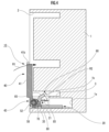
- FIG. 1 is an exploded perspective view showing an embodiment of an opening/closing device for an opening/closing body according to the present invention
- FIG. 2 is an enlarged perspective view of an opening/closing body constituting an opening/closing device of the opening/closing body, as viewed from a direction different from that of FIG. 1
- 11 is a cross-sectional view of the opening/closing body with an opening/closing device fixed to a fixed member and with the opening/closing body closed relative to an opening of the fixed member.
- FIG. FIG. 5 is an enlarged cross-sectional view of a main portion of FIG. 4 .
- 3 is a cross-sectional view taken along the line AA of FIG. 2.
- FIG. 1 is a plan view of an opening/closing device for an opening/closing body according to the present invention
- 3 is a cross-sectional view taken along the line BB of FIG. 2.
- 5 is a cross-sectional view of the state in which the opening/closing body is opened relative to the opening of the fixed member in the state shown in FIG. 4 .
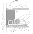
- FIG. 10 is an enlarged cross-sectional view of a main portion of FIG. 9 .
- 10 is a cross-sectional view of the state in which an insertion member is inserted into the opening of the fixed member in the state shown in FIG. 9 .
- FIG. 12 is an enlarged cross-sectional view of a main portion of FIG. 11 .
- FIG. 11 is an enlarged cross-sectional view of a main portion of another embodiment of the opening/closing device for an opening/closing body according to the present invention.
- a fixed member 1 that is provided with a charging port for an electric vehicle or the like is provided with an opening 2 for normal charging and an opening 3 for rapid charging.
- An insert member 5 such as a power supply gun is inserted into the openings 2 and 3.
- an opening/closing body 40 such as a lid, which is a member that constitutes the opening/closing body opening/closing device 10 of the present invention (hereinafter also simply referred to as "opening/closing device 10"), is attached to the opening 3 so that it can be opened and closed.
- the opening/closing device 10 in this embodiment is, for example, a device for opening and closing the opening/closing body 40 relative to the opening of the fixed member 1 (here, the opening 3 for rapid charging).
- the plug-in member 5 is inserted into the openings 2 and 3 to charge the battery (not shown) of the electric vehicle, forming a so-called charging gun.
- the fixed member is not limited to a member having a charging port for an electric vehicle, but may be other members.
- the opening is also not limited to an opening for quick charging, but may be other parts.
- this opening/closing device 10 has a base member 20 fixed to a fixed member 1, an opening/closing body 40 that is rotatably attached to the base member 20 via a first pivot support part to open and close the opening 3 and has an engaged part 58, a locking member 60 that is rotatably attached to the base member 20 via a second pivot support part and has an abutment part 65 with which the insertion member 5 abuts and an engagement part 70 that engages with the engaged part 58 when the opening/closing body is opened relative to the opening 3 to hold the opening/closing body 40 in an open state, and a biasing member 80.
- the biasing member 80 has a wound portion 81 formed by winding a metal wire, a first arm portion 83 extending from one end of the wound portion 81, and a second arm portion 85 extending from the other end of the wound portion 81.
- the fixed member 1 has a receiving portion 1a for receiving and fixing the base member 20 of the opening/closing device 10, and also has an insertion groove 1b that communicates with the opening 3 for inserting and removing the locking member 60 of the opening/closing device 10.
- the first pivot support portion is provided between the base member 20 and the opening/closing body 40.
- the first pivot support portion is composed of a pair of support holes 27, 27 provided on the base member 20 side, and shaft portions 50, 52 provided on the opening/closing body 40 side.
- the central axis (axis center) that is the radial center of the support hole 27, passes through the radial center of the shaft portions 50, 52 and runs along the axial direction is defined as the pivot axis C1 of the first pivot support portion (see FIG. 8).
- the second rotation support part is provided between the base member 20 and the locking member 60.
- the second rotation support part is composed of a shaft part 35 provided on the base member 20 side and a support part 63 provided on the locking member 60 side.
- the central axis (axis center) that passes through the radial center of the shaft part 35 and runs along the axial direction, and the radial center of the support part 63, is set as the rotation axis C2 of the second rotation support part (see Figure 8).
- the opening/closing body 40 has a first locking portion 54, and the first arm portion 83 is locked to this first locking portion 54, biasing the opening/closing body 40 in the direction of closing the opening 3 (see arrow R1).
- the locking member 60 also has a second engaging portion 74, and the second arm portion 85 is engaged with this second engaging portion 74 (see FIG. 6).
- the locking member 60 is biased in the direction opposite to the biased direction (direction R1) of the opening/closing body 40, and in such a way that the abutment portion 65 enters the insertion path F2 (hereinafter also referred to simply as "insertion path F2 of the insertion member 5"; see FIGS. 9 and 10) along the insertion direction F1 of the insertion member 5 into the opening 3 (see arrow R2).
- a stopper portion is provided between the base member 20 and the locking member 60, the stopper portion being made up of the inner edge portion 38 of the recess 37 of the base member 20 and the tip portion 75 and flange portion 77 of the projection 73 of the locking member 60.
- a stopper portion is provided between the opening/closing body 40 and the locking member 60, the stopper portion being made up of the abutting end portion 57a of the recessed groove 57 of the opening/closing body 40 and the engaging portion 70 of the locking member 60.
- this embodiment has two stopper portions.
- the base member 20 in this embodiment has a substantially rectangular frame shape having a bottom wall portion 21 in the shape of a substantially rectangular plate and a pair of side walls 23, 25 standing on a pair of opposing sides of the bottom wall portion 21 and extending a predetermined length.
- a locking member 60 is disposed between the pair of side walls 23, 25 (see FIG. 7).
- One side wall portion 23 is disposed on the front side of the paper in FIG. 1, and the other side wall portion 25 is disposed on the back side of the paper in FIG. 1.
- the direction in which the side walls 23 and 25 extend is referred to as the "extension direction X.”
- a circular support hole 27 is formed on one end side of each side wall portion 23, 25 in the extension direction X (left side of the paper in FIG. 1).
- the shaft portions 50, 52 of the opening/closing body 40 are inserted into the pair of support holes 27, 27, respectively, and are supported for rotation. As a result, the opening/closing body 40 is rotatably attached to the base member 20 (see FIG. 2).
- extension direction Y The direction in which the pair of side walls 23, 25 are arranged and the axes of the shafts 50, 52 face is referred to as the "axial direction Y.” Furthermore, the direction perpendicular to the extension direction X and perpendicular to the axial direction Y is referred to as the "height direction Z.” Note that the above “extension direction X,” “axial direction Y,” and “height direction Z” have the same meanings for other members (opening/closing body 40, locking member 60, etc.) other than the base member 20.
- an extension portion 29 extends from the other end side of the bottom wall portion 21 in the extension direction X (the right side of the paper in FIG. 1) and the center in the axial direction Y.
- the tip portion 29a of this extension portion 29 is removably inserted and fixed into a fixing recess (not shown) formed in the accommodation portion 1a of the fixed member 1, so that the base member 20 is removably fixed to the fixed member 1.
- a guide surface 31 is formed on the end face of one end of the bottom wall portion 21 in the extension direction X, and in the range from one end in the axial direction Y (the end on the front side of the paper in FIG. 1) to the middle of the axial direction Y (see FIG. 6).
- This guide surface 31 is curved to fit the outer peripheral surface of the peripheral wall portion 47 (see FIG. 3) that constitutes the axial structure portion 43 of the opening/closing body 40, and serves as a rotation guide for the axial structure portion 43 when the opening/closing body 40 rotates.
- a substantially rectangular cutout hole 33 is formed at one end of the bottom wall 21 in the extension direction X and near the side wall 25, and the shaft 50 is provided through this cutout hole 33.
- the shaft portion 50 is generally cylindrical with its axis parallel to the axial direction Y, with one end in the axial direction Y connected to one inner side of the notched hole 33 and the other end in the axial direction Y connected to the other inner side of the notched hole 33. In other words, both axial ends of the shaft portion 50 are bridged across both inner sides of the notched hole 33.
- the shaft portion 50 is also positioned such that a predetermined portion of it (here, roughly the upper half of the shaft portion 50) protrudes from the inner surface of the bottom wall portion 21 (see Figure 6).
- the shaft portion 50 is supported by the support portion 63 of the locking member 60, so that the locking member 60 is rotatably attached to the base member 20.
- a recess 37 is formed on the inner surface of the side wall 25 (the surface facing the side wall 23) at the other end in the extension direction X, recessed from the inner surface toward the outer surface to a predetermined depth.
- the tip 75 and flange 77 of the protrusion 73 of the locking member 60 are adapted to be rotatably inserted into this recess 37.
- an inner edge 38 is formed on one end side of the recess 37 on the extension direction X side (also called the first pivot support side). This inner edge 38 is formed parallel to the height direction Z. Also, an inclined surface 39 is formed from one end of the inner edge 38 in the height direction Z (the bottom end of the paper in Figure 1) to the other end in the extension direction X, the height of which gradually decreases toward the other end.
- the tip 75 and flange 77 of the projection 73 of the locking member 60 abut against the inner edge 38 of the recess 37, preventing the locking member 60 from coming off the base member 20.
- the opening/closing body 40 in this embodiment has a cover body 41 that is generally plate-shaped and extends long in the axial direction Y with four chamfered corners, an extension portion 42 that extends from the middle of one long side 41a of the cover body 41 in the axial direction Y, and an axis structure portion 43 that is connected to the cover body 41 via the extension portion 42.
- the shaft structure 43 has a first wall 45 extending along the extension direction of the extension portion 42, a second wall 46 extending diagonally outward relative to the extension direction of the extension portion 42, a peripheral wall 47 that connects the extension direction tip ends of the first wall 45 and the second wall 46 to each other and has a curved outer periphery, and a side wall 48 that connects one end of each wall 45, 46, 47 in the axial direction Y (the front side of the paper in FIG. 1) to each other.
- a roughly cylindrical shaft portion 50 protrudes from the outer surface of the side wall portion 48. This shaft portion 50 is inserted into the support hole 27 in the side wall portion 23 of the base member 20 (see Figure 2).
- the other end side of the shaft structure 43 in the axial direction Y is cut out by a notch 49, and a recessed accommodation recess 51 is formed in which the winding portion 81 of the biasing member 80 is accommodated.
- a generally cylindrical shaft portion 52 protrudes from the bottom surface 51a of the storage recess 51 so as to be coaxial with the shaft portion 50.
- This shaft portion 52 is inserted into a support hole 27 formed on the side wall portion 23 side of the base member 20.
- the shaft portion 52 is inserted inside the winding portion 81 housed in the storage recess 51, and the winding portion 81 is fitted onto the shaft portion 52.
- the pair of shafts 50, 52 are inserted into the pair of support holes 27, 27 and are supported for rotation, so that the opening/closing body 40 is rotatably attached to the base member 20. That is, in this embodiment, the pair of shafts 50, 52 of the opening/closing body 40 and the pair of support holes 27, 27 of the base member 20 form the "first rotation support portion" of the present invention.
- a first engagement portion 54 having a slit groove shape is formed at a position adjacent to the first wall portion 45 of the peripheral wall portion 47 constituting the shaft structure portion 43, and is cut out from the other end face in the axial direction Y by a predetermined length toward one end side in the axial direction Y.
- the first arm 83 of the biasing member 80 is inserted into and engaged with this first locking portion 54 (see Figures 3 and 6), so that the opening/closing body 40 is biased in the direction of closing the opening 3, as shown by arrow R1.
- the opening/closing body 40 is biased to rotate in the R1 direction by the biasing force from the first arm 83 of the biasing member 80.
- a shallow concave arm insertion groove 55 is formed at the boundary between the tip of the second wall portion 46 in the extension direction and the other end of the peripheral wall portion 47 in the axial direction Y.
- the second arm portion 85 of the biasing member 80 is inserted from this arm insertion groove 55 (see Figs. 3 and 6).
- a groove 57 extending in the circumferential direction from the second wall portion 46 side toward the first wall portion 45 side, and an engaged portion 58 formed in a position adjacent to the groove 57. It can also be said that the engaged portion 58 is provided between the groove 57 and the first engaging portion 54 having a slit groove shape.
- one circumferential end of the groove 57 (the end farthest from the engaged portion 58) is the abutting end 57a.
- the engaging portion 70 of the locking member 60 abuts against or separates from this abutting end 57a (see Figures 5, 10, and 12).
- the engaged portion 58 is recessed, and has a concave curved surface 58a that is curved in an arc shape, and apexes 58b and 58c that are provided on both circumferential ends and protrude the highest.
- the apex 58b is located on the first engaging portion 54 side, and the apex 58c is located on the recessed groove 57 side.
- the engaging portion 70 of the locking member 60 engages with the concave curved surface 58a of the engaged portion 58, thereby holding the opening/closing body 40 in an open state relative to the opening 3 against the biasing force of the biasing member 80 (the biasing force from the first arm portion 83).
- the engaging portion 70 of the locking member 60 and the abutting end portion 57a of the recessed groove 57 come into contact with each other. That is, the abutting end portion 57a of the recessed groove 57 of the opening/closing body 40, which is biased to rotate in the R1 direction by the biasing force from the first arm portion 83 of the biasing member 80, and the engaging portion 70 of the locking member 60, which is biased to rotate in the R2 direction by the biasing force from the second arm portion 85 of the biasing member 80, come into contact while pressing against each other.
- the locking member 60 in this embodiment has a base 61 in the shape of a rectangular block extending a predetermined length, a support portion 63 provided at one end of the base 61 in the extension direction, and an abutment portion 65 provided at the other end of the base 61 in the extension direction.
- the support portion 63 has a pair of clamping claws 67, 67 that are separated via a notch 66 and are capable of bending and deforming.
- the pair of clamping claws 67, 67 have an outer periphery that expands in diameter in a roughly arc shape, and the inner periphery is an arc-shaped curved surface.
- a slit 68 is formed midway in the extension direction of the base 61 toward the support portion 63, making both side edge portions of the slit 68 easier to bend, and thus making the pair of clamping claws 67, 67 easier to bend.
- the pair of clamping claws 67, 67 are pressed against the shaft portion 35 of the base member 20 from the cutout 66 side, and the pair of clamping claws 67, 67 are flexibly deformed while clamping the shaft portion 35, so that the locking member 60 is attached to the base member 20 in a rotatable and non-removable state, as shown in FIG. 5.
- the shaft portion 35 of the base member 20 and the pair of clamping claws 67, 67 of the support portion 63 of the locking member 60 form the "second rotation support portion" in the present invention.
- a convex engaging portion 70 protrudes from the front surface 61a (the surface facing the opening/closing body 40) of the base 61, near the support portion 63.
- This engaging portion 70 is a roughly semicircular convex portion with a curved outer periphery so as to fit the concave curved surface 58a of the engaged portion 58.
- the engaging portion 70 which is a convex portion, engages with the concave curved surface 58a of the engaged portion 58 of the opening/closing body 40 (this can also be said to be a convex-concave fit), thereby holding the opening/closing body 40 in an open state relative to the opening 3 against the biasing force of the biasing member 80 (the biasing force from the first arm portion 83).
- the abutment portion 65 is bent at a predetermined angle relative to the extension direction of the base 61 at the other end side of the extension direction of the base 61 (here, the abutment portion 65 is bent relative to the base 61 so as to form a roughly V-shape).
- the surface of the abutment portion 65 facing the opening/closing body 40 forms the abutment surface 65a.
- the locking member 60 rotates in the opposite direction to the R2 direction, which is the biasing direction, against the biasing force of the biasing member 80 (the biasing force from the second arm portion 85), and the engaging portion 70, which is a convex portion, comes out of the concave curved surface 58a of the engaged portion 58, and the engagement between the engaged portion 58 and the engaging portion 70 is released.
- the abutting end 57a of the groove 57 of the opening/closing body 40 and the engagement portion 70 of the locking member 60 form a single stopper portion provided between the opening/closing body 40 and the locking member 60.
- a protrusion 73 is formed from the abutment portion 65 of the locking member 60, protruding toward one side wall portion 25 of the base member 20, and the base end of the protrusion 73 in the protruding direction forms the second locking portion (the protrusion 73 protrudes from the abutment portion 65 via a protruding piece 72).
- a protrusion 72 protrudes (or protrudes out) from the other end edge of the abutment portion 65 in the axial direction Y on the rear side opposite the abutment surface 65a, so as to form a generally triangular plate together with the abutment portion 65.
- a projection 73 protrudes from the outer surface of the tip end (the end separated from the abutment surface 65a) in the protruding direction of the protrusion 72, parallel to the rotation axis C2 of the second rotation support portion, and toward the side wall portion 25 of the base member 20.
- the base end of the projection 73 in the protruding direction forms the second locking portion 74.
- the second arm 85 of the biasing member 80 is locked to this second locking portion 74.
- the locking member 60 is biased in the opposite direction (R1 direction) to the direction in which the opening/closing body 40, which is engaged and biased by the first arm portion 83 of the biasing member 80, is biased, and so that the abutment portion 65 enters the insertion path F2 of the insertion member 5.
- the locking member 60 is biased to rotate in the R2 direction by the biasing force from the second arm portion 85 of the biasing member 80.
- a flange portion 77 is provided from the tip portion 75 of the projection 73 in the protruding direction so as to be positioned between the side wall portion 25 of the base member 20 and the second arm portion 85 of the biasing member 80 (see Figures 2 and 7).
- a plate-shaped flange portion 77 projects from the outer peripheral edge of the tip portion 75 of the projection 73 on the support portion 63 side in parallel with the extension direction of the base portion 61 and toward the support portion 63 side.
- This flange portion 77 fits into the recess 37 formed in the side wall portion 25 of the base member 20 together with the tip portion 75 of the protrusion 73, and rotates within the recess 37 when the locking member 60 rotates relative to the base member 20. In other words, it serves as a rotation guide for the locking member 60.
- the tip 75 and flange 77 of the projection 73 of the locking member 60 abut against the inner edge 38 of the recess 37 formed in the side wall 25 of the base member 20, preventing the locking member 60 from coming off the base member 20.
- the inner edge 38 of the recess 37 of the base member 20 and the tip 75 and flange 77 of the protrusion 73 of the locking member 60 form another stopper portion provided between the base member 20 and the locking member 60.
- the rotation axis C1 of the opening/closing body 40 and the rotation axis C2 of the locking member 60 are arranged parallel to each other, and the winding portion 81 of the biasing member 80 and the locking member 60 are arranged to overlap in a direction perpendicular to the rotation axis C1 of the opening/closing body 40 and the rotation axis C2 of the locking member 60.
- the base member may have an overall shape of a box or a cylinder with a bottom.
- the cover of the opening/closing body may be a circular plate or an elliptical plate.
- an axis structure may be provided on the inner surface side of the cover (the surface side facing the opening).
- the locking member may be, for example, columnar, cylindrical, square columnar, or square tube-shaped, as long as it has at least a shape that includes an abutment portion.
- the first rotation support part may be provided by providing an axle on the base member side and a support hole on the opening/closing body side to support the axle rotationally, or by providing support holes on both the base member and the opening/closing body and inserting and supporting a separate shaft through these support holes.
- the second rotation support part may be provided by providing an axle on the lock member side and a bearing part on the base member side.
- the stopper portion may be provided only between the base member and the locking member, or between the opening/closing body and the locking member. Note that an embodiment in which the stopper portion is provided only between the base member and the locking member will be described later.
- the engaged portion may be a convex portion and the engaging portion may be a concave portion, or both the engaged portion and the engaging portion may be projections that engage with each other.
- the insertion member 5 is inserted into the openings 2 and 3 of the fixed member 1 along the insertion direction F1, and the insertion member 5 is inserted into the openings 2 and 3 to a predetermined depth as shown in Figures 11 and 12.
- the tip of the insertion member 5 abuts against and is pressed against the abutment surface 65a of the abutment portion 65 of the locking member 60, causing the locking member 60 to rotate in the direction opposite to the R2 direction against the biasing force from the second arm portion 85 of the biasing member 80.
- the abutment portion 65 is released from the insertion path F2 of the insertion member 5.
- the engaging portion 70 of the locking member 60 comes out of the concave curved surface 58a of the engaged portion 58 of the opening/closing body 40, and the engagement between the engaged portion 58 and the engaging portion 70 is released, so that the opening/closing body 40 rotates in the R1 direction due to the biasing force from the first arm portion 83 of the biasing member 80.
- the tip of the contact surface 65a of the contact portion 65 contacts the outer peripheral surface of the insertion member 5, restricting the rotation of the locking member 60 in the R2 direction.
- the plug-in member 5 is pulled out from the openings 2, 3 of the fixed member 1.
- the opening/closing body 40 to which a biasing force is applied from the first arm 83 of the biasing member 80 via the first engagement portion 54, rotates in the R1 direction to close the opening 3 again
- the locking member 60 to which a biasing force is applied from the second arm 85 of the biasing member 80 via the second engagement portion 74, rotates in the R2 direction, and its abutment portion 65 again enters the insertion path F2 of the insertion member 5, returning to the state shown in Figures 4 and 5.
- the engaging portion 70 of the locking member 60 abuts against the abutment end portion 57a of the groove 57 of the opening/closing body 40, and as shown in FIG. 7, the tip portion 75 and flange portion 77 of the projection 73 of the locking member 60 abut against the inner edge portion 38 of the recess 37 of the base member 20, restricting further rotation of the locking member 60 in the R2 direction (the rotation stopper functions), and preventing the locking member 60 from coming off the base member 20 (the anti-slip stopper functions).
- the first arm 83 of the biasing member 80 is engaged with the first engagement portion 54 of the opening/closing body 40, thereby biasing the opening/closing body 40 in the R1 direction, which is the direction in which the opening/closing body 40 closes the opening 3, and the second arm 85 of the biasing member 80 is engaged with the second engagement portion 74 of the locking member 60, thereby biasing the locking member 60 in the R2 direction, which is the opposite direction to R1, which is the direction in which the opening/closing body 40 is biased, and so that the abutment portion 65 enters the insertion path F2 of the insertion member 5.
- one biasing member 80 can bias two members, the opening/closing body 40 and the locking member 60, simultaneously, which reduces the number of parts in the opening/closing device 10 and simplifies the structure of the opening/closing device 10.
- the rotation axis C1 of the opening/closing body 40 and the rotation axis C2 of the locking member 60 are arranged parallel to each other, and the winding portion 81 of the biasing member 80 and the locking member 60 are arranged to overlap in a direction perpendicular to the rotation axis C1 of the opening/closing body 40 and the rotation axis C2 of the locking member 60.
- the winding portion 81 of the biasing member 80 and the locking member 60 are arranged to overlap in a direction perpendicular to the rotation axis C1 of the opening/closing body 40 and the rotation axis C2 of the locking member 60, so that the opening/closing device 10 can have a compact structure while stably applying the biasing force from the second arm portion 85 of the biasing member 80 to the locking member 60.
- a pair of side walls 23, 25 are provided on the base member 20, a locking member 60 is disposed between the pair of side walls 23, 25, a first pivot support portion (a pair of support holes 27, 27 and a pair of shaft portions 50, 52) is provided on the side walls 23, 25 and the locking member 60, the biasing member 80 is disposed offset toward one of the side walls 25, a protrusion 73 is formed from the abutment portion 65 of the locking member 60 and protrudes toward one of the side walls 25, and the base end of the protrusion 73 in the protruding direction forms a second engaging portion 74 (see Figures 2, 7, 8, etc.).
- a protrusion 73 is formed from the abutment portion 65 of the locking member 60, protruding toward one side wall portion 25 and having a base end portion in the protruding direction that forms the second engagement portion 74. This makes it easier to engage the second arm portion 85 of the biasing member 80 with the second engagement portion 74 at the base end portion of the protrusion 73 when attaching the locking member 60 to the base member 20, thereby improving the ease of attachment (assembly) of the locking member 60 to the base member 20.
- a recess 37 is formed on the inner surface of one of the side walls 25 of the base member 20 into which the protrusion of the locking member 60 fits, and the tip 75 of the protrusion 73 in the protruding direction abuts against the inner edge 38 on the first rotation support side of the recess 37 to hold the locking member 60 in place and prevent it from slipping out of the base member 20, with the inner edge 38 and the tip 75 of the protrusion 73 forming a stopper portion (see Figures 2 and 7, etc.).
- the inner edge 38 on the first rotation support side of the recess 37 on the base member 20 side and the tip 75 of the protrusion 73 of the locking member 60 form a stopper portion, so that while a stopper portion of the locking member 60 is provided, the stopper portion wraps in the thickness direction of the side wall portion 25, making it possible to further compactify the opening and closing device 10.
- a flange portion 77 is provided from the tip portion 75 of the projection 73 in the protruding direction, protruding so as to be positioned between one side wall portion 25 and the second arm portion 85 of the biasing member 80 (see Figures 2 and 7).
- the flange portion 77 configured as described above can prevent the second arm portion 85 of the biasing member 80 from contacting one of the side walls 25, so that the biasing force from the second arm portion 85 of the biasing member 80 can be stably applied to the locking member 60.
- the biasing force from the second arm 85 of the biasing member 80 can be reliably applied only to the second engaging portion 74 of the locking member 60 without being dispersed toward the base member 20, so that the biasing force can be stably applied to the locking member 60.
- stopper portions are provided at two locations, between the base member 20 and the locking member 60, and between the opening/closing body 40 and the locking member 60, to prevent the locking member 60 from coming off the base member 20.
- a first stopper portion is provided between the base member 20 and the locking member 60, and is made up of the inner edge portion 38 of the recess 37 of the base member 20 and the tip portion 75 and flange portion 77 of the projection 73 of the locking member 60
- a second stopper portion is provided between the opening/closing body 40 and the locking member 60, and is made up of the abutment end portion 57a of the recessed groove 57 of the opening/closing body 40 and the engagement portion 70 of the locking member 60, providing two stopper portions.
- the locking member 60 can be more reliably held against the base member 20 to prevent it from coming loose.
- FIG. 13 Another embodiment of the opening and closing device for an opening and closing body according to the present invention is shown in Fig. 13. Note that parts substantially the same as those in the above embodiment are given the same reference numerals and the description thereof will be omitted.
- An opening/closing device 10A of an opening/closing body in this embodiment (hereinafter, also simply referred to as "opening/closing device 10A") has a different structure of a stopper portion from that in the above-described embodiment.
- a protruding stopper protrusion 36 is provided on the other edge in the height direction Z of the inner surface of the side wall portion 25 of the base member 20, between the axis C1' of the opening/closing body 40 and the axis C2' of the locking member 60.
- the stopper projection 36 has a tapered tip surface 36a facing the opening/closing body 40, and is configured not to interfere with the peripheral wall portion 47 of the shaft structure portion 43 when the opening/closing body 40 rotates.
- the base end surface 36b of the stopper projection 36 opposite the tip surface 36a is a vertical surface along the height direction Z.
- the front surface 61a of the base 61 of the locking member 60 which is biased to rotate by the second arm 85 of the biasing member 80, abuts against the base end surface 36b of the stopper protrusion 36, restricting the rotation of the locking member 60 and preventing the locking member 60 from coming off the base member 20 (functioning as a stopper to prevent it coming off).
Landscapes
- Engineering & Computer Science (AREA)
- Transportation (AREA)
- Mechanical Engineering (AREA)
- Life Sciences & Earth Sciences (AREA)
- Sustainable Development (AREA)
- Sustainable Energy (AREA)
- Chemical & Material Sciences (AREA)
- Combustion & Propulsion (AREA)
- Power Engineering (AREA)
- Pivots And Pivotal Connections (AREA)
Priority Applications (1)
| Application Number | Priority Date | Filing Date | Title |
|---|---|---|---|
| JP2025534060A JPWO2025018335A1 (https=) | 2023-07-20 | 2024-07-16 |
Applications Claiming Priority (2)
| Application Number | Priority Date | Filing Date | Title |
|---|---|---|---|
| JP2023-118663 | 2023-07-20 | ||
| JP2023118663 | 2023-07-20 |
Publications (1)
| Publication Number | Publication Date |
|---|---|
| WO2025018335A1 true WO2025018335A1 (ja) | 2025-01-23 |
Family
ID=94281558
Family Applications (1)
| Application Number | Title | Priority Date | Filing Date |
|---|---|---|---|
| PCT/JP2024/025480 Pending WO2025018335A1 (ja) | 2023-07-20 | 2024-07-16 | 開閉体の開閉装置 |
Country Status (2)
| Country | Link |
|---|---|
| JP (1) | JPWO2025018335A1 (https=) |
| WO (1) | WO2025018335A1 (https=) |
Citations (6)
| Publication number | Priority date | Publication date | Assignee | Title |
|---|---|---|---|---|
| US5382171A (en) * | 1992-08-04 | 1995-01-17 | Schoeller & Co. | Electric socket especially for motor vehicles |
| JP2016219242A (ja) * | 2015-05-20 | 2016-12-22 | トヨタ自動車株式会社 | 充電コネクタ接続装置 |
| JP2017155449A (ja) * | 2016-02-29 | 2017-09-07 | 株式会社パイオラックス | ハウジングユニット及び開閉体のロック装置 |
| JP2018065532A (ja) * | 2016-10-21 | 2018-04-26 | 豊田合成株式会社 | フィラーリッド構造体 |
| WO2018149468A1 (de) * | 2017-02-15 | 2018-08-23 | Dr. Ing. H.C. F. Porsche Aktiengesellschaft | Anschlussvorrichtung zum aufladen einer batterievorrichtung eines fahrzeugs |
| JP2019018673A (ja) * | 2017-07-14 | 2019-02-07 | 株式会社ニフコ | 車両のリッド装置 |
-
2024
- 2024-07-16 WO PCT/JP2024/025480 patent/WO2025018335A1/ja active Pending
- 2024-07-16 JP JP2025534060A patent/JPWO2025018335A1/ja active Pending
Patent Citations (6)
| Publication number | Priority date | Publication date | Assignee | Title |
|---|---|---|---|---|
| US5382171A (en) * | 1992-08-04 | 1995-01-17 | Schoeller & Co. | Electric socket especially for motor vehicles |
| JP2016219242A (ja) * | 2015-05-20 | 2016-12-22 | トヨタ自動車株式会社 | 充電コネクタ接続装置 |
| JP2017155449A (ja) * | 2016-02-29 | 2017-09-07 | 株式会社パイオラックス | ハウジングユニット及び開閉体のロック装置 |
| JP2018065532A (ja) * | 2016-10-21 | 2018-04-26 | 豊田合成株式会社 | フィラーリッド構造体 |
| WO2018149468A1 (de) * | 2017-02-15 | 2018-08-23 | Dr. Ing. H.C. F. Porsche Aktiengesellschaft | Anschlussvorrichtung zum aufladen einer batterievorrichtung eines fahrzeugs |
| JP2019018673A (ja) * | 2017-07-14 | 2019-02-07 | 株式会社ニフコ | 車両のリッド装置 |
Also Published As
| Publication number | Publication date |
|---|---|
| JPWO2025018335A1 (https=) | 2025-01-23 |
Similar Documents
| Publication | Publication Date | Title |
|---|---|---|
| US4087145A (en) | Magnetic tape cartridge case with biasing means | |
| JPS5928543Y2 (ja) | カセツトケ−ス | |
| JPH03195000A (ja) | Icキャリア | |
| US4646191A (en) | Recording tape cassette | |
| CN114761654B (zh) | 解锁装置 | |
| WO2025018335A1 (ja) | 開閉体の開閉装置 | |
| US5315336A (en) | Battery housing structure | |
| JP2025015328A (ja) | 開閉体の開閉装置 | |
| JP2001084975A (ja) | 電池収納装置 | |
| JP4112160B2 (ja) | テープカートリッジ | |
| JP2017141000A (ja) | 車両用ボードのハンドル装置 | |
| JP3098379B2 (ja) | 収納体 | |
| JP2538720Y2 (ja) | カセットハーフの収納ケース | |
| JPH0454615Y2 (https=) | ||
| JPH08153551A (ja) | コネクタ | |
| JP2006298301A (ja) | 可動式収納ポケット | |
| JP2003036926A (ja) | レバー式コネクタ | |
| JP2798157B2 (ja) | テープカートリッジ | |
| JPH01254929A (ja) | 電池収容用蓋部開閉機構 | |
| JPH087590Y2 (ja) | テープカセット | |
| JPH0713108Y2 (ja) | テープカセット | |
| JPS63234479A (ja) | テ−プカ−トリツジ | |
| JPS6316063Y2 (https=) | ||
| JPH063829Y2 (ja) | テ−プカ−トリツジの収納ケ−ス | |
| JPS6312463Y2 (https=) |
Legal Events
| Date | Code | Title | Description |
|---|---|---|---|
| 121 | Ep: the epo has been informed by wipo that ep was designated in this application |
Ref document number: 24843125 Country of ref document: EP Kind code of ref document: A1 |
|
| ENP | Entry into the national phase |
Ref document number: 2025534060 Country of ref document: JP Kind code of ref document: A |
|
| WWE | Wipo information: entry into national phase |
Ref document number: 2025534060 Country of ref document: JP |
|
| NENP | Non-entry into the national phase |
Ref country code: DE |