WO2025013287A1 - 加工シミュレーション装置 - Google Patents
加工シミュレーション装置 Download PDFInfo
- Publication number
- WO2025013287A1 WO2025013287A1 PCT/JP2023/025897 JP2023025897W WO2025013287A1 WO 2025013287 A1 WO2025013287 A1 WO 2025013287A1 JP 2023025897 W JP2023025897 W JP 2023025897W WO 2025013287 A1 WO2025013287 A1 WO 2025013287A1
- Authority
- WO
- WIPO (PCT)
- Prior art keywords
- tool
- speed
- model
- machining
- simulation device
- Prior art date
- Legal status (The legal status is an assumption and is not a legal conclusion. Google has not performed a legal analysis and makes no representation as to the accuracy of the status listed.)
- Pending
Links
Images

Classifications
-
- B—PERFORMING OPERATIONS; TRANSPORTING
- B23—MACHINE TOOLS; METAL-WORKING NOT OTHERWISE PROVIDED FOR
- B23Q—DETAILS, COMPONENTS, OR ACCESSORIES FOR MACHINE TOOLS, e.g. ARRANGEMENTS FOR COPYING OR CONTROLLING; MACHINE TOOLS IN GENERAL CHARACTERISED BY THE CONSTRUCTION OF PARTICULAR DETAILS OR COMPONENTS; COMBINATIONS OR ASSOCIATIONS OF METAL-WORKING MACHINES, NOT DIRECTED TO A PARTICULAR RESULT
- B23Q15/00—Automatic control or regulation of feed movement, cutting velocity or position of tool or work
-
- G—PHYSICS
- G05—CONTROLLING; REGULATING
- G05B—CONTROL OR REGULATING SYSTEMS IN GENERAL; FUNCTIONAL ELEMENTS OF SUCH SYSTEMS; MONITORING OR TESTING ARRANGEMENTS FOR SUCH SYSTEMS OR ELEMENTS
- G05B19/00—Program-control systems
- G05B19/02—Program-control systems electric
- G05B19/18—Numerical control [NC], i.e. automatically operating machines, in particular machine tools, e.g. in a manufacturing environment, so as to execute positioning, movement or co-ordinated operations by means of program data in numerical form
- G05B19/406—Numerical control [NC], i.e. automatically operating machines, in particular machine tools, e.g. in a manufacturing environment, so as to execute positioning, movement or co-ordinated operations by means of program data in numerical form characterised by monitoring or safety
- G05B19/4069—Simulating machining process on screen
Definitions
- the present invention relates to a processing simulation device.
- a machining simulation device that simulates the operation of the machine tool may be used to check the suitability of the machining program, specifically to check for interference between the tool and other objects, such as unintended contact of the tool with the workpiece.
- a machining simulation device uses a three-dimensional tool model of the tool and a three-dimensional model of the workpiece, etc., to simulate the operation of the machine tool and, in turn, the presence or absence of interference (see, for example, Patent Document 1).
- the operation of a machine tool is achieved by outputting an interpolation pulse generated by a numerical control device to a servo motor, but there is a technology that simulates the machine operation after output of this interpolation pulse to the servo motor before outputting it, predicts in advance whether the tool will interfere with another object, and stops output of the interpolation pulse to the servo motor if interference occurs (see, for example, Patent Document 2).
- a 3D tool model of a tool has a fixed shape and is defined by data described in a specific format, such as an STL file.
- some tools change shape when rotated.
- a tool with an eccentric shape occupies a larger space when rotating than when not rotating. For this reason, it is necessary to confirm that the tool does not interfere with other objects by making the model shape of the tool the sum of the spaces that it can occupy at each rotation speed.
- there is a possibility that the tool will be judged to interfere even when interference does not occur at the actual rotation speed, and a machining simulation device that can more accurately confirm tool interference is desired.
- a machining simulation device is a machining simulation device that simulates the operation of a machine tool including a tool and a workpiece, and includes a speed acquisition unit that acquires speed information indicating the rotational speed of the tool, a tool model acquisition unit that acquires a tool model that corresponds to the speed information acquired by the speed acquisition unit and whose shape can change depending on the rotational speed, a simulation execution unit that executes a simulation of the machining operation of the workpiece by the tool in the machine tool using the tool model acquired by the tool model acquisition unit, and an interference confirmation unit that confirms interference of the tool with another object based on the result of the simulation by the simulation execution unit.
- FIG. 1 is a block diagram showing a configuration of a processing simulation device according to a first embodiment of the present disclosure.
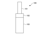
- FIG. 2 is a schematic side view showing a tool model of a chip blower tool when not rotating.
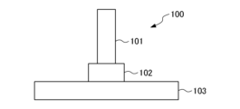
- FIG. 3 is a schematic side view showing a tool model of the same chip blower tool as in FIG. 2 during high speed rotation.
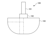
- FIG. 3 is a schematic side view showing a tool model of the same chip blower tool as in FIG. 2 , covering a range from no rotation to high speed rotation.
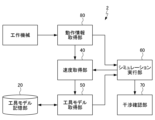
- FIG. 11 is a block diagram showing a configuration of a processing simulation device according to a second embodiment of the present disclosure.
- Figure 1 is a block diagram showing the configuration of a machining simulation device 1 according to a first embodiment of the present disclosure.
- the machining simulation device 1 simulates the operation of a machine tool including a tool and a workpiece based on a machining program.
- the machining simulation device 1 includes a program storage unit 10, a tool model storage unit 20, a program analysis unit 30, a speed acquisition unit 40, a tool model acquisition unit 50, a simulation execution unit 60, and an interference confirmation unit 70.
- the machining simulation device 1 can be realized by having one or more computer devices having a memory, a processor, an input/output interface, etc. execute an appropriate processing program.
- Each component of the machining simulation device 1 is a classification of the function of the machining simulation device 1, and does not have to be clearly distinguishable in terms of physical configuration and program configuration.
- the program storage unit 10 stores at least a portion of the machining program.
- the program storage unit 10 has a working memory space that stores the portion necessary to execute a simulation of the machining program.
- the machining program may be written in a well-known language such as G-code.
- the configuration of the program storage unit 10 may be the same as that in a well-known machining simulation device.
- the tool model storage unit 20 stores one or more tool models that model the three-dimensional shape of the space occupied by the tool.
- the tool models may be stored as well-known data files such as STL files. At least one of the tool models stored in the tool model storage unit 20 changes shape depending on the rotation speed. For this reason, the tool model storage unit 20 stores the relationship between the rotation speed of the tool (which may be a value of the speed information described later) and the tool model (the shape of the space occupied by the tool).
- the tool model storage unit 20 may define at least a part of the shape of the space occupied by the tool, such as the diameter, length, angle, etc., as a function of the rotational speed of the tool, but it is more convenient to classify the rotational speed of the tool into multiple categories and register one tool model for each category to which the rotational speed belongs.
- the tool model of the tool stored in the tool model storage unit 20 preferably has the shape of a rotating body of the tool when the rotational speed has a value.
- the shape of the cross section including the rotation axis of the tool model is preferably constant regardless of the cross section angle. This makes it possible to reduce the calculation load since it is not necessary to take into account the rotational angle position of the tool when checking for interference with the tool.
- the tool model may be a non-rotating body whose cross section shape differs depending on the cross section angle.
- a tool whose occupied space changes shape according to the rotation speed typically has a movable part whose posture changes according to the rotation speed, and the actual shape changes.
- the tool model storage unit 20 preferably stores the relationship between the rotation speed and the tool model derived from the posture of the movable part. This makes it possible to more accurately represent the shape of the occupied space of the tool that changes according to the rotation speed.
- a specific example of a tool whose actual shape changes according to the rotation speed is a chip blower tool.
- a chip blower tool has multiple blower blades that are swingably attached to a rotating shaft as movable parts, and when the rotation speed is low, the blower blades extend in the axial direction to reduce the diameter of the entire tool, and when the rotation speed is high, the blower blades are deployed by centrifugal force to spread outward in the radial direction. For this reason, the diameter and axial length of the tool model of the chip blower tool change according to the rotation speed.
- the tool model may be one of three types: a rotating body shape applied when the rotation speed is sufficiently small (no rotation or low rotation speed) and when the attitude of the moving part is in the initial state; a rotating body shape applied when the rotation speed is sufficiently high and when the attitude of the moving part has changed to a limit state; and a rotating body shape that includes all attitudes of the moving part and is applied when the attitude of the moving part cannot be specified because the rotation speed is in an intermediate region that does not fall under the above two cases and is unclear.
- the tool model storage unit 20 may store a tool model of a rotating body shape when the attitude of the moving part is in the initial state, a tool model of a rotating body shape that includes all attitudes of the moving part, and a tool model of a rotating body shape when the attitude of the moving part has changed to a limit state.
- FIG. 2 shows a tool model 100 of a chip blower tool when it is not rotating (or when it is rotating at a low speed below a predetermined rotation speed)
- FIG. 3 shows a tool model 100 of the same chip blower tool when it is rotating at high speed
- FIG. 4 shows a tool model 100 that includes all shapes of the same chip blower tool.
- the tool model 100 of the chip blower tool has a round bar-shaped shaft portion 101 that models a shaft that is coaxially attached to the main shaft of a machine tool, a disk-shaped holding portion 102 that models a holding portion that swingably holds multiple blower blades, and a transforming portion 103 that is a rotor containing multiple blower blades and changes shape depending on the rotation speed. If the rotation speed range in which the posture of the movable portion is in a limit state is small, the tool model storage unit 20 may store two tool models by dividing the rotation speed into two sections: no rotation (or low-speed rotation region) and all other rotation speed regions (including when the rotation speed is unknown).
- the shape of the tool model can be changed according to the rotation speed.
- the tool model storage unit 20 stores two tool models, one for when the rotation speed is zero and one for when the rotation speed has a value (other than zero).
- the program analysis unit 30 analyzes the machining program and derives command values that specify the position, posture, and rotational speed of the tool for each control cycle according to the machining program.
- the configuration of the program analysis unit 30 can be the same as that of a known machining simulation device.
- the speed acquisition unit 40 acquires speed information indicating the rotational speed of the tool.
- the rotational speed of the tool is obtained by the analysis of the machining program in the program analysis unit 30 or the analysis of the state of the machine tool in the simulation execution unit 60.
- the speed information is preferably at least one of the following: a spindle speed command value (a value output according to the machining program), a spindle speed estimate value (an estimate of the spindle rotational speed estimated from the current value of the spindle motor in the simulation, an estimate of the spindle rotational speed estimated from the gear ratio, or an estimate of the spindle rotational speed during acceleration/deceleration estimated from the acceleration/deceleration of the spindle).
- the rotational speed of the tool may differ from the spindle rotational speed, for example, when the tool is driven by the spindle via a gear.
- the drive current frequency of the spindle motor, etc. may also be used as the speed information.
- the tool model acquisition unit 50 acquires a tool model corresponding to the speed information acquired by the speed acquisition unit 40 from the tool model storage unit 20.
- the tool model acquisition unit 50 may be configured to transmit the speed information or the tool rotational speed converted from the speed information to the tool model storage unit 20 and acquire a data file of the corresponding tool model from the tool model storage unit 20.
- the tool model acquisition unit 50 may also be configured to identify the tool to be used based on the tool number described in the machining program and acquire a tool model corresponding to the identified tool rotational speed.
- the tool model acquisition unit 50 may also be configured to generate or modify a tool model based on the information acquired from the tool model storage unit 20.
- the simulation execution unit 60 uses the tool model acquired by the tool model acquisition unit 50 to perform a simulation of the machining operation of the workpiece by the tool in the machine tool. Specifically, the simulation execution unit 60 places the tool model acquired by the tool model acquisition unit 50 and a model of the workpiece, etc. in a virtual space, and moves the tool model within the virtual space based on the machining program.
- the configuration of the simulation execution unit 60 can be the same as that of a known machining simulation device, except that a tool model whose shape changes depending on the rotation speed is used.
- the interference checking unit 70 checks whether or not the tool interferes with other objects, that is, whether or not there is unintended overlap between the tool model and a model of another object such as a workpiece, based on the results of the simulation performed by the simulation execution unit 60. Typically, the interference checking unit 70 determines that the tool will interfere with other objects when the tool model and the model of the workpiece overlap spatially while the tool model is being moved from one machining point to the next machining point, and when the tool model and the model of an object other than the workpiece overlap spatially. If it is determined that the tool will interfere with other objects, the interference checking unit 70 can be configured to notify the user of this fact, thereby urging the user to modify the machining program.
- the configuration of the interference checking unit 70 can be the same as that in known machining simulation devices.
- the machining simulation device 1 having the above configuration changes the shape of the tool model according to the rotation speed of the tool to check for interference of the tool with other objects. Therefore, interference between the tool and other objects can be checked using a tool model that represents the shape of the minimum necessary occupying space according to the rotation speed of the tool, making it possible to prevent erroneous detection of interference when no interference actually occurs.
- FIG. 5 is a block diagram showing the configuration of a processing simulation device 2 according to a fifty-second embodiment of the present disclosure.
- components similar to those in the processing simulation device 1 of FIG. 1 will be given the same reference numerals, and duplicate descriptions may be omitted.
- the machining simulation device 2 uses information generated by a numerical control device to simulate the operation of a machine tool including a tool and a workpiece.
- the machining simulation device 2 can be configured to predict interference between a tool and other objects in advance by simulating future command values calculated in advance by reading ahead the machining program in the machine tool's control device before the machine tool executes it.
- the machining simulation device 2 can be configured to predict interference between a tool and other objects in advance by simulating the machine operation when an interpolation pulse is output to a motor in a numerical control device that performs interpolation processing to move the motor, before outputting the pulse to the motor.
- the machining simulation device 2 can stop the machine tool before the tool actually interferes with another object.
- the machining simulation device 2 comprises a tool model storage unit 20, an operation information acquisition unit 80, a speed acquisition unit 40, a tool model acquisition unit 50, a simulation execution unit 60, and an interference confirmation unit 70.
- the machining simulation device 2 is realized by causing one or more computer devices to execute appropriate processing programs, and its components are classifications of the functions of the machining simulation device 2.
- the operation information acquisition unit 80 acquires various types of operation information that indicate the state of the machine tool. Specifically, the operation information acquisition unit 80 acquires from the machine tool, as operation information, information necessary to identify the operating state of the machine tool in a simulation of the operation of the machine tool, such as the tools used by the machine tool, interpolation pulses, position information of each axis, and the rotational speed of the spindle measured by equipment such as an encoder. The operation information acquisition unit 80 may convert the information acquired from the machine tool into operation information to be used in the simulation as necessary.
- the speed acquisition unit 40 acquires speed information indicating the rotational speed of the tool (actual spindle speed) from the analysis results of the state of the machine tool in the operation information acquired by the operation information acquisition unit 80.
- the tool model acquisition unit 50 acquires from the tool model storage unit 20 a tool model that corresponds to the tool used by the machine tool acquired by the operation information acquisition unit 80 and the speed information acquired by the speed acquisition unit 40.
- the simulation execution unit 60 places the tool model and the model of the workpiece, etc. acquired by the tool model acquisition unit 50 in a virtual space, and moves the tool model and the model of the workpiece, etc. in the virtual space at a speed corresponding to the speed of each axis acquired by the operation information acquisition unit 80.
- the interference checking unit 70 checks whether the tool will interfere with another object based on the results of the simulation performed by the simulation execution unit 60. If it is determined that the tool will interfere with another object, the interference checking unit 70 can stop the machine tool before the tool actually interferes with the other object by sending an emergency stop signal to the machine tool.
- the machining simulation device (1) is a machining simulation device (1) that simulates the operation of a machine tool including a tool and a workpiece, and includes a speed acquisition (40) that acquires speed information indicating the rotational speed of the tool by analyzing a machining program or a state of the machine tool, a tool model acquisition unit (50) that acquires a tool model whose shape can change depending on the rotational speed and corresponds to the speed information acquired by the speed acquisition unit (40), a simulation execution unit (60) that executes a simulation of the machining operation of the workpiece by the tool in the machine tool using the tool model acquired by the tool model acquisition unit (50), and an interference confirmation unit (70) that confirms interference of the tool with another object based on a result of the simulation by the simulation execution unit (60).
- the machining simulation device (1) of supplementary note 1 or 2 may further include a tool model storage unit (20) that stores a relationship between the rotational speed of the tool and the tool model.
- the tool may include a movable part whose posture changes according to the rotation speed, and the tool model storage unit (20) may store a relationship between the speed information and a tool model derived from the posture of the movable part.
- the tool model may have a shape of a rotating body of the tool when the rotational speed has a value.
- the machining simulation device may not include a tool model storage unit, and may acquire a tool model corresponding to tool speed information from an external device.
- the tool model storage unit may be provided in an external device.
- the machining simulation device according to the present disclosure may be configured as one unit with a numerical control device that controls a machine tool.
- the machining simulation device according to the present disclosure may be realized as one function of a control device for a machine tool.
- REFERENCE SIGNS LIST 1 Machining simulation device 10 Program storage unit 20 Tool model storage unit 30 Program analysis unit 40 Speed acquisition unit 50 Tool model acquisition unit 60 Simulation execution unit 70 Interference checking unit 80 Operation information acquisition unit
Landscapes
- Engineering & Computer Science (AREA)
- Human Computer Interaction (AREA)
- Manufacturing & Machinery (AREA)
- Physics & Mathematics (AREA)
- General Physics & Mathematics (AREA)
- Automation & Control Theory (AREA)
- Mechanical Engineering (AREA)
- Numerical Control (AREA)
Priority Applications (2)
| Application Number | Priority Date | Filing Date | Title |
|---|---|---|---|
| JP2025532352A JPWO2025013287A1 (cg-RX-API-DMAC7.html) | 2023-07-13 | 2023-07-13 | |
| PCT/JP2023/025897 WO2025013287A1 (ja) | 2023-07-13 | 2023-07-13 | 加工シミュレーション装置 |
Applications Claiming Priority (1)
| Application Number | Priority Date | Filing Date | Title |
|---|---|---|---|
| PCT/JP2023/025897 WO2025013287A1 (ja) | 2023-07-13 | 2023-07-13 | 加工シミュレーション装置 |
Publications (1)
| Publication Number | Publication Date |
|---|---|
| WO2025013287A1 true WO2025013287A1 (ja) | 2025-01-16 |
Family
ID=94214866
Family Applications (1)
| Application Number | Title | Priority Date | Filing Date |
|---|---|---|---|
| PCT/JP2023/025897 Pending WO2025013287A1 (ja) | 2023-07-13 | 2023-07-13 | 加工シミュレーション装置 |
Country Status (2)
| Country | Link |
|---|---|
| JP (1) | JPWO2025013287A1 (cg-RX-API-DMAC7.html) |
| WO (1) | WO2025013287A1 (cg-RX-API-DMAC7.html) |
Citations (4)
| Publication number | Priority date | Publication date | Assignee | Title |
|---|---|---|---|---|
| US3200673A (en) * | 1964-05-22 | 1965-08-17 | Degussa | Tool for fine cutting |
| JP2011110614A (ja) * | 2009-11-24 | 2011-06-09 | Kanto Auto Works Ltd | 切屑排除工具 |
| JP2011251383A (ja) * | 2010-06-03 | 2011-12-15 | Fanuc Ltd | 工具回転半径可変の工具ホルダおよび該工具を備えた工作機械ならびに前記工作機械を用いた加工方法 |
| WO2014128890A1 (ja) * | 2013-02-21 | 2014-08-28 | 三菱電機株式会社 | 干渉チェック装置および数値制御装置 |
-
2023
- 2023-07-13 JP JP2025532352A patent/JPWO2025013287A1/ja active Pending
- 2023-07-13 WO PCT/JP2023/025897 patent/WO2025013287A1/ja active Pending
Patent Citations (4)
| Publication number | Priority date | Publication date | Assignee | Title |
|---|---|---|---|---|
| US3200673A (en) * | 1964-05-22 | 1965-08-17 | Degussa | Tool for fine cutting |
| JP2011110614A (ja) * | 2009-11-24 | 2011-06-09 | Kanto Auto Works Ltd | 切屑排除工具 |
| JP2011251383A (ja) * | 2010-06-03 | 2011-12-15 | Fanuc Ltd | 工具回転半径可変の工具ホルダおよび該工具を備えた工作機械ならびに前記工作機械を用いた加工方法 |
| WO2014128890A1 (ja) * | 2013-02-21 | 2014-08-28 | 三菱電機株式会社 | 干渉チェック装置および数値制御装置 |
Also Published As
| Publication number | Publication date |
|---|---|
| JPWO2025013287A1 (cg-RX-API-DMAC7.html) | 2025-01-16 |
Similar Documents
| Publication | Publication Date | Title |
|---|---|---|
| JP7338743B2 (ja) | 診断装置、診断方法、プログラムおよび診断システム | |
| US11036199B2 (en) | Control device, control program, and control method for anomaly detection | |
| JP6156566B2 (ja) | 診断装置、診断方法、プログラムおよび診断システム | |
| JP6553508B2 (ja) | Cncコントローラに組み込まれたcam機能を有するコンピュータ数値制御(cnc)システム及びcnc機械を修正する方法 | |
| US12085912B2 (en) | Information processing apparatus, information processing method, and information processing program | |
| CN111052015A (zh) | 数控系统及电动机控制装置 | |
| JP2018097662A (ja) | 制御装置、制御プログラムおよび制御方法 | |
| JP2021505990A (ja) | ツールパス仮想化および最適化システム、方法および装置 | |
| US11454952B2 (en) | Numerical control apparatus | |
| JP7518171B2 (ja) | ポストプロセッサ開発支援装置、ポストプロセッサ開発支援システム、及びコンピュータが実行可能な方法 | |
| WO2025013287A1 (ja) | 加工シミュレーション装置 | |
| JP2023092934A (ja) | 情報処理装置 | |
| JP7479571B2 (ja) | パラメータ調整装置、工作機械システムおよびパラメータ調整方法 | |
| WO2022138055A1 (ja) | 情報処理装置および情報処理プログラム | |
| Neugebauer et al. | Realistic machine simulation with virtual reality | |
| JP3764436B2 (ja) | 機械の制御装置 | |
| WO2025069314A1 (ja) | 制御装置 | |
| JP2022143423A (ja) | 診断装置、診断システム、診断方法及び診断プログラム | |
| JP7618067B2 (ja) | 表示装置、数値制御装置、加工システム、表示方法、数値制御方法および加工方法 | |
| JP6997360B1 (ja) | 数値制御装置、加工システムシミュレータ及び数値制御プログラム | |
| JP3857662B2 (ja) | 系統間軸交換制御機能を有する多系統数値制御装置 | |
| JP7822534B1 (ja) | ワイヤ放電加工装置、ワイヤ放電加工方法、制御プログラムおよびワイヤ放電加工システム | |
| WO2025134408A1 (ja) | 演算装置、加工システム、演算方法およびプログラム | |
| JP2002091526A (ja) | 数値制御装置 | |
| Hardwick et al. | Enabling machining vision using STEP-NC |
Legal Events
| Date | Code | Title | Description |
|---|---|---|---|
| 121 | Ep: the epo has been informed by wipo that ep was designated in this application |
Ref document number: 23945160 Country of ref document: EP Kind code of ref document: A1 |
|
| ENP | Entry into the national phase |
Ref document number: 2025532352 Country of ref document: JP Kind code of ref document: A |
|
| WWE | Wipo information: entry into national phase |
Ref document number: 2025532352 Country of ref document: JP |
|
| NENP | Non-entry into the national phase |
Ref country code: DE |