WO2025009563A1 - 塗装鋼板 - Google Patents
塗装鋼板 Download PDFInfo
- Publication number
- WO2025009563A1 WO2025009563A1 PCT/JP2024/024107 JP2024024107W WO2025009563A1 WO 2025009563 A1 WO2025009563 A1 WO 2025009563A1 JP 2024024107 W JP2024024107 W JP 2024024107W WO 2025009563 A1 WO2025009563 A1 WO 2025009563A1
- Authority
- WO
- WIPO (PCT)
- Prior art keywords
- coating layer
- steel sheet
- particles
- resin
- rust
- Prior art date
- Legal status (The legal status is an assumption and is not a legal conclusion. Google has not performed a legal analysis and makes no representation as to the accuracy of the status listed.)
- Ceased
Links
Images

Classifications
-
- C—CHEMISTRY; METALLURGY
- C23—COATING METALLIC MATERIAL; COATING MATERIAL WITH METALLIC MATERIAL; CHEMICAL SURFACE TREATMENT; DIFFUSION TREATMENT OF METALLIC MATERIAL; COATING BY VACUUM EVAPORATION, BY SPUTTERING, BY ION IMPLANTATION OR BY CHEMICAL VAPOUR DEPOSITION, IN GENERAL; INHIBITING CORROSION OF METALLIC MATERIAL OR INCRUSTATION IN GENERAL
- C23C—COATING METALLIC MATERIAL; COATING MATERIAL WITH METALLIC MATERIAL; SURFACE TREATMENT OF METALLIC MATERIAL BY DIFFUSION INTO THE SURFACE, BY CHEMICAL CONVERSION OR SUBSTITUTION; COATING BY VACUUM EVAPORATION, BY SPUTTERING, BY ION IMPLANTATION OR BY CHEMICAL VAPOUR DEPOSITION, IN GENERAL
- C23C28/00—Coating for obtaining at least two superposed coatings either by methods not provided for in a single one of groups C23C2/00 - C23C26/00 or by combinations of methods provided for in subclasses C23C and C25C or C25D
- C23C28/30—Coatings combining at least one metallic layer and at least one inorganic non-metallic layer
- C23C28/32—Coatings combining at least one metallic layer and at least one inorganic non-metallic layer including at least one pure metallic layer
- C23C28/322—Coatings combining at least one metallic layer and at least one inorganic non-metallic layer including at least one pure metallic layer only coatings of metal elements only
- C23C28/3225—Coatings combining at least one metallic layer and at least one inorganic non-metallic layer including at least one pure metallic layer only coatings of metal elements only with at least one zinc-based layer
Definitions
- the present invention relates to coated steel sheets.
- the present inventors have conducted intensive research and come up with the following idea. That is, if the surface of the particles contained in the organic resin coating layer and having a particle diameter larger than the average film thickness can be covered with an organic resin, the interface between the large particle and the binder resin layer can be made long. In addition, according to the "long interface between the large particle and the binder resin layer", a certain part of the particle protruding from the binder resin layer is covered with a film-forming component, so that the exposed part of the particle can be reduced. In addition, by making the interface between the large particle and the binder resin layer long in this way, the intrusion of corrosion factors can be suppressed, and corrosion can be suppressed.
- the present inventors have conducted detailed research on the application conditions of a paint containing particles having a particle diameter larger than the average film thickness. As a result, the inventors have found that when the average particle size of the particles, the average film thickness of the organic resin coating layer, the thickness of the organic resin coating the surfaces of the particles, etc. satisfy certain conditions, it is possible to prevent particles from falling off from the organic resin coating layer and to prevent deformation, thereby achieving further improvements in the design and productivity of the coated steel sheet.
- the gist of the present invention which was completed based on these findings, is as follows.
- At least one side of a steel sheet having a Zn-containing plating layer It has two or more coating layers including an anti-rust coating layer,
- the 60 degree specular gloss GS(60 °) of the coating layer on at least one surface of the steel plate as defined in JIS Z 8741:1997 is 20% or less;
- the average thickness of the anticorrosive coating layer is 5 ⁇ m or more and 15 ⁇ m or less,
- the anticorrosive coating layer comprises a binder resin, a crosslinking agent, and an anticorrosive pigment;
- a coated steel sheet wherein the ratio of the anti-rust pigment to the total area of the anti-rust coating film layer is, in terms of area ratio, 30% or more and 60% or less.
- the anti-rust pigment contains at least one of Si, P, Mg, and V.
- the Si includes at least one of calcium ion-exchanged silica and magnesium ion-exchanged silica
- the P includes at least one of zinc phosphate, magnesium dihydrogen phosphate, and aluminum dihydrogen tripolyphosphate
- the Mg includes at least one of magnesium dihydrogen phosphate, magnesium oxide, and magnesium hydroxide.
- the steel plate has, on the surface having a 60 degree specular gloss GS(60°) of 20% or less, the rust-preventive coating film layer as a lower layer of the two or more coating layers, and a colored coating film layer as an outermost layer located on the side furthest from the steel plate, the colored coating film layer containing resin particles, and a binder resin, a crosslinking agent, and a color pigment as film-forming components,
- the average particle size is a value obtained by measuring the circle equivalent diameters of the resin particles present in one observation field of view on the cross section, calculating the average of the two largest circle equivalent diameters among the circle equivalent diameters, and similarly averaging the average values obtained for any 10 observation fields of view by the number of fields of view.
- the coated steel sheet according to [1] or [2] above having one or two of the following characteristics selected from: on the surface of the steel sheet where the 60 degree specular gloss GS(60°) is 20% or less, the surface roughness of the steel sheet is 2 ⁇ m or more in Ra; or the coating layer contains 15% or more of an aggregate composed of a pigment containing silica.
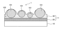
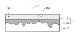
- FIG. 1 is a schematic diagram for explaining an example of a structure of a coated steel plate according to an embodiment of the present invention.
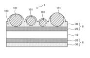
- FIG. 2 is a schematic diagram for explaining an example of the structure of a coated steel plate according to the embodiment.
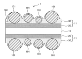
- FIG. 2 is a schematic diagram for explaining an example of a structure of a coated steel plate according to the embodiment.
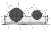
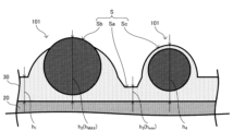
- FIG. 2 is a schematic diagram for explaining an outermost coating layer in the coated steel plate according to the embodiment.
- FIG. 2 is a schematic diagram for explaining an outermost coating layer in the coated steel sheet according to the embodiment.
- FIG. 11 is a schematic diagram for explaining a thin film portion in a coated steel plate according to another embodiment.
- FIG. 11 is a schematic diagram for explaining a thin film portion in a coated steel plate according to still another embodiment.
- various steel sheets can be used as the base material, that is, the steel sheet 10.
- various steel sheets can be used, such as Al-killed steel, extra-low carbon steel containing Ti, Nb, etc., and high-strength steel in which extra-low carbon steel further contains strengthening elements such as P, Si, Mn, etc.
- a sheet containing a small amount of different metal elements or impurities such as cobalt, molybdenum, tungsten, nickel, titanium, chromium, aluminum, manganese, iron, magnesium, lead, bismuth, antimony, tin, copper, cadmium, arsenic, etc. in the above plating, or a sheet having inorganic substances such as silica, alumina, and titania dispersed therein may be used.
- the zinc-based plated steel sheet a steel sheet having a multi-layer plating that combines the above plating with other types of plating (e.g., iron plating, iron-phosphorus plating, nickel plating, cobalt plating, etc.) may be used.
- the plating method is not particularly limited, and various known plating methods such as electroplating, hot-dip plating, vapor deposition plating, dispersion plating, vacuum plating, etc. may be used.
- the thickness of the steel plate 10 as described above is not particularly limited, and may be set appropriately depending on the mechanical strength (e.g., tensile strength, etc.) and workability required for the coated steel plate 1 according to this embodiment.
- the anti-rust pigment contained in the anti-rust coating layer 20 can be any of various known anti-rust pigments that contain at least one of the elements P, V, Si, and Mg.
- the average thickness of the rust-preventive coating layer 20 is preferably 12 ⁇ m or less.
- the ratio of the presence of the anti-rust pigment to the total area of the anti-rust coating layer 20 is calculated as follows. That is, as in the case of the above-mentioned average film thickness measurement, attention is paid to a cross section obtained by cutting the coating film 11 according to this embodiment in the thickness direction at an arbitrary position. In the cross section of interest, attention is paid to one observation field area (length in the width direction: 40 ⁇ m). In this case, the magnification of the FE-SEM may be an appropriate magnification (for example, about 3000 times) such that a length of 40 ⁇ m in the width direction fits in one field of view.
- the area ratio (i.e., area ratio) of the anti-rust pigment in the total area of the anti-rust coating layer 20 in the observation field area of such size is calculated by various functions implemented in the electron microscope, image processing, etc.
- 10 measured values of the area ratio of the anti-rust pigment can be obtained.
- the average value of the 10 measured values obtained in this way is calculated to be the average area ratio of the anti-rust pigment in the cross section.
- this average area ratio is the average value of the area ratio of the anti-rust pigment to the total area of the anti-rust coating layer 20 in the 10 observed viewing areas.
- This average value is the abundance ratio of the anti-rust pigment.
- the anti-rust pigment in the coating 11 can be identified by confirming the elements present in the particles present in the coating 11 by EDS analysis (energy dispersive X-ray spectroscopy).
- organic resin particles used as particles 101 include resin particles made of acrylic resin, resin particles made of polyester resin, resin particles made of urethane resin, resin particles made of fluorine resin, resin particles made of silicone resin, and resin particles made of polyolefin resin. Among these, from the viewpoint of more easily achieving the desired toughness and ductility, it is more preferable to use resin particles made of urethane resin or resin particles made of acrylic resin as particles 101. Among these, it is even more preferable to use resin particles whose main component is acrylic resin as particles 101.
- the particles 101 may contain multiple types of particles with different average particle sizes.
- the particles 101 may also function as various additives that can be added to the outermost coating layer 30, such as colorants and rust inhibitors.
- the binder resin 103 as a film-forming component contained in the outermost coating layer 30 according to this embodiment can be any material as long as it functions as a binder for the particles 101.
- various organic resins as the binder resin 103.
- binder resins 103 include acrylic resins, polyester resins, urethane resins, and fluorine resins. Among them, it is even more preferable to use a binder resin whose main component is an acrylic resin or a polyester resin.
- the abundance ratio of particles 101 in the cross section described above in the outermost coating layer 30 of this embodiment is the average area ratio (i.e., average area ratio), which is the area ratio of particles 101 in the outermost coating layer 30, and is in the range of 5% or more and 30% or less.
- the average area ratio of particles 101 in the cross section is less than 5%, the presence ratio of particles 101 is too small and the desired design cannot be achieved. If the average area ratio of particles 101 is 5% or more, it is possible to achieve an excellent design that combines a grained appearance and a matte appearance.
- the average area ratio of particles 101 in the cross section is preferably 10% or more, and more preferably 15% or more.
- the average thickness T of the outermost coating layer 30 in the cross section not containing particles 101 exceeds 40 ⁇ m, the thickness of the outermost coating layer 30 becomes too thick, and the adhesion of the outermost coating layer 30 decreases, which is not preferred.
- the average thickness T 40 ⁇ m or less it is possible to achieve the desired corrosion resistance while ensuring the adhesion of the outermost coating layer 30.
- the average thickness T is preferably 35 ⁇ m or less, and more preferably 25 ⁇ m or less.
- the average thickness T of the outermost coating layer 30 in the portion not containing the particles 101 in the above cross section is determined by the following procedure. First, as in the case of the above-mentioned anticorrosive coating layer 20, attention is paid to a cross section obtained by cutting the coating film 11 according to this embodiment in the thickness direction at an arbitrary position. In one observation field of view of interest, the thickness of the outermost coating layer 30 in the portion not containing the particles 101 is measured at at least 10 points. At this time, the thickness of the outermost coating layer 30 in the portion not containing the particles 101 may be measured using a length measuring function or the like implemented in the FE-SEM.
- the average value of the obtained three or more measurements is calculated, and this is taken as the average value of the thickness of the outermost coating layer 30 in the observation field of view of interest.
- the above operation is performed for any 10 observation fields of interest, and the average values obtained from each observation field of view are further averaged by the number of fields of view. The value obtained in this manner is taken as the average thickness T of the outermost coating layer 30 in the portion not containing the particles 101.
- the average value of the thickness of the outermost coating layer 30 in one observation field of view of interest is (1/3) x ( T1 + T2 + T3 ).
- Such observation is performed for any 10 observation field of view areas, and the obtained average values are further averaged by the number of fields of view to obtain the average thickness T of the outermost coating layer 30 in the portion not containing particles 101.
- the average particle diameter ⁇ 10 of the particles 101 specified by a procedure described below is 2 to 5 times the average film thickness T (hereinafter simply referred to as "average film thickness T") in the portion of the outermost coating layer 30 that does not contain resin particles.
- the average particle diameter ⁇ 10 of the particles 101 is preferably 2.1 times or more, more preferably 2.2 times or more, more preferably 2.3 times or more, more preferably 2.4 times or more, and most preferably 2.5 times or more, relative to the average film thickness T of the outermost coating layer 30.
- the particles 101 have an average particle size ⁇ 10 that is preferably 4.5 times or less, more preferably 4 times or less, and most preferably 3.5 times or less, the average film thickness T of the outermost coating layer 30 .
- the protruding portion of the particle 101 protruding from the surface position in the part of the outermost coating layer 30 that does not contain resin particles (hereinafter referred to as the "protruding portion P") is covered with a film-forming component having a thickness of 0.5 ⁇ m or more over more than half of the length along the outer periphery of the protruding portion (hereinafter referred to as the "circumferential length L 1 of the protruding portion").
- the portion located above the dotted line segment B connecting the surface position of the outermost coating layer 30 in the portion where the particle 101 does not exist is the protruding portion P.
- the portion of the protruding portion P of the particle 101 covered with a film-forming component having a thickness of 0.5 ⁇ m or more is referred to as the "particle-covered portion C"
- the portion of the particle 101 not covered with a film-forming component having a thickness of 0.5 ⁇ m or more is referred to as the "particle-exposed portion E".
- the protruding portion P of the particle 101 is covered with a film-forming component for more than half of the length along the outer periphery of the protruding portion P
- the ratio (L 2 /L 1 ) of the length along the outer periphery of the protruding portion P in the particle-covered portion C (hereinafter referred to as the "particle-covered portion circumferential length L 2 " ) to the protruding portion circumferential length L 1 is 1/2 or more.
- the entire protruding portion P may be covered with a film-forming component.
- the peripheral length L 1 of the protruding portion and the peripheral length L 2 of the particle-covered portion are equal to each other, and the ratio (L 2 /L 1 ) is 1.
- the protruding portion circumferential length L1 and the particle-coated portion circumferential length L2 are equal, and it is clear that the ratio ( L2 / L1 ) is 1, so measurement is omitted.
- a dotted line segment B is specified that connects the surface positions of the outermost coating layer 30 in the portion where the particles 101 do not exist. The length of the arc connecting the two intersections between the line segment B and the outer periphery of the particle 101 is measured and set as the protruding portion circumferential length L1 .
- the length L21 of the arc connecting the left one of the two intersections of the line segment B and the outer periphery of the particle 101 and the left one of the two points on the outer periphery of the particle 101 at the boundary between the particle-coated portion C and the particle-exposed portion E, and the length L22 of the arc connecting the right one of the two intersections of the line segment B and the outer periphery of the particle 101 and the right one of the two points on the outer periphery of the particle 101 at the boundary between the particle-coated portion C and the particle-exposed portion E are measured, and the sum of the arc lengths L21 and L22 is the particle-coated portion circumferential length L2.
- the protruding portion circumferential length L1 and the arc lengths L21 and L22 can be calculated by various functions implemented in the electron microscope, image processing, etc. Furthermore, the above ratio ( L2 / L1 ) is calculated. When the ratio ( L2 / L1 ) calculated in this manner for each particle 101 is 1/2 or more, it can be said that "the protruding portion P of the particle 101 is covered with the film-forming component for half or more of the length along the outer periphery of the protruding portion P.” In addition, in Figure 2, point G is the center of gravity of the particle 101.
- the ratio ( L2 / L1 ) of the protruding portion circumferential length L1 to the particle-coated portion circumferential length L2 of the particles 101 is most preferably 100%.
- the particle exposed portion E may expand depending on the usage state, and the ratio ( L2 / L1 ) may exceptionally be outside the range of the above specification. Therefore, the ratio ( L2 / L1 ) of the protruding portion circumferential length L1 to the particle-coated portion circumferential length L2 of the particles 101 may be 60% or more, more preferably 80% or more.
- the average particle size of all particles 101 is preferably 15 ⁇ m or more when the thickness of the anti-rust coating film is 10 ⁇ m.
- the average particle size of all particles 101 is preferably 40 ⁇ m or less when the thickness of the anti-rust coating film is 10 ⁇ m.
- the average particle size of all particles 101 is less than 15 ⁇ m, the average particle size of the particles 101 is too small to achieve the desired design and scratch resistance.
- the average particle size of all particles 101 is 15 ⁇ m or more, the design and scratch resistance required for the coated steel plate 1 according to this embodiment can be more effectively achieved.
- the average particle size of the particles 101 is more preferably 18 ⁇ m or more, and even more preferably 20 ⁇ m or more.
- the average particle size of the particles 101 exceeds 40 ⁇ m, the average particle size of the particles 101 becomes too large, and as a result, there is a risk that particles may be missing during the manufacturing process.
- the average particle size of the particles 101 is more preferably 30 ⁇ m or less.
- the average particle size of all the particles 101 can be measured in the same manner as the average particle size ⁇ 10 of the top 10 particles 101. Specifically, in one observation field when calculating the average particle size ⁇ 10 , the average value of the circle equivalent diameters of all the particles 101 in that observation field is calculated. Such a measurement is performed for any 10 observation field regions, and the average values obtained from each observation field region are further averaged by the number of fields. The value obtained in this manner is the average particle size of all the particles 101.
- the ratio ( HMAX / Hmin ) of the maximum film thickness HMAX to the minimum film thickness Hmin is preferably 5 or more and 20 or less.
- the ratio ( HMAX / Hmin ) is in the above range, the value of the 60-degree specular gloss Gs (60°) of the outermost coating layer 30 can be made more preferable. This results in a more excellent matte appearance (and thus a more excellent design).
- the ratio ( HMAX / Hmin ) is 5 or more, the tactile feel of the surface of the coated steel plate 1 can be made preferable.
- the ratio ( HMAX / Hmin ) of the maximum film thickness HMAX is more preferably 6 or more, and even more preferably 7.5 or more. Moreover, the ratio (H MAX /H min ) is more preferably 17.5 or less, and further more preferably 15 or less.
- the portion of the outermost coating layer 30 with the minimum film thickness H min may be a thin film portion.
- the coated steel sheet 1 according to this embodiment includes the rust-preventive coating layer 20, and therefore can suppress corrosion on the surface of the steel sheet 10 even if a corrosion factor penetrates.
- the ratio (H MAX /H min ) of the maximum film thickness H MAX to the minimum film thickness H min is specified by the following procedure.
- a length measuring function implemented in the FE-SEM is used to identify the part of the minimum film thickness h min and the part of the maximum film thickness h MAX , and the film thicknesses of each are measured.
- the above-mentioned operation is performed for 10 arbitrary observation field of views.
- the smallest value among the minimum film thicknesses h min obtained from each observation field of view is set as the minimum film thickness H min
- the largest value among the maximum film thicknesses h MAX is set as the maximum film thickness H MAX .
- the ratio (H MAX /H min ) of the maximum film thickness H MAX to the minimum film thickness H min is specified from the obtained values.
- the portion of minimum thickness h min is the portion where the outermost layer is the thinnest in each visual field, and where the distance between the surface in contact with the rust-preventive coating layer 20 and the exposed surface S is the shortest.
- the portion of maximum thickness h MAX is the portion where the outermost coating layer 30 is the thickest in each visual field, and where the distance between the surface in contact with the rust-preventive coating layer 20 and the exposed surface S is the longest.
- the above “distance” is a direction perpendicular to the in-plane direction of the steel sheet 10.
- the "exposed surface S" in the outermost coating layer 30 includes the exposed surface Sa of the binder resin 103 in the portion where the particles 101 are not present, the exposed surface Sb of the particle exposed portion E of the particle 101, and the exposed surface Sc of the binder resin 103 in the particle-coated portion C.
- the portions with thicknesses h 1 and h 3 are the thicknesses h 1 and h 3 , respectively, of the surface in contact with the rust-preventive coating layer 20 and the exposed surface Sa of the binder resin 103 in the portion where the particles 101 are not present.
- the portion with thickness h 2 is the thickness h 2 , which is the distance between the surface in contact with the rust-preventive coating layer 20 and the exposed surface Sb in the particle exposed portion E.
- the distance between the surface in contact with the rust-preventive coating layer 20 and the exposed surface Sc of the binder resin 103 in the particle-coated portion C is the thickness h4 .
- the minimum film thickness h min and the maximum film thickness h MAX in identifying the minimum film thickness h min and the maximum film thickness h MAX , the largest of the film thicknesses h 1 to h 4 is h 2 , and this portion is identified as the portion with the maximum film thickness h MAX . Also, the smallest is h 3 , and this portion is identified as the portion with the minimum film thickness h min . In the above cross-sectional observation, the minimum film thickness h min and the maximum film thickness h MAX are identified in this manner.
- the outermost coating layer 30 may have any other desired configuration, such as not including the particles 101, so long as the 60 degree specular gloss G S (60°) of the outermost coating layer 30 is 20% or less.
- the outermost coating layer 30 may include a thin film portion 200 when observed in a cross section cut in the thickness direction at any position of the coating film 11.
- Figures 3A and 3B are cross-sectional views showing the configuration of a coated steel plate 1 including an outermost coating layer 30 including a thin film portion 200. If a defect or the like occurs in the thin film portion 200, corrosion factors are likely to penetrate through the defect. In contrast, the coated steel plate 1 according to this embodiment includes the above-mentioned rust-preventive coating layer 20, and therefore corrosion on the surface of the steel plate 10 can be suppressed even if a corrosion factor penetrates.
- the portion between the coated steel plate 1 and the recesses of the outermost coating layer 30 may correspond to the thin film portion 200.
- the thin film portion 200 is, for example, 20 ⁇ m or less.
- the outermost coating layer 30 may contain 1% or more of a curing catalyst, causing the outermost coating layer 30 to harden and shrink, resulting in irregularities.
- the portion between the convex portions of the coated steel plate 1 and the outermost coating layer 30 may correspond to the thin film portion 200.
- the thin film portion 200 is, for example, 20 ⁇ m or less.
- the coated steel plate 1 has a rough surface shape with certain irregularities
- a case where the surface roughness of the coated steel plate 1 is 2 ⁇ m or more in Ra can be considered.
- a steel sheet serving as a base material is subjected to various pretreatments, including an alkaline degreasing treatment, a water washing treatment, and an acid pickling treatment, to prepare a clean steel sheet surface.
- anti-rust paints for forming an anti-rust coating layer are applied to the steel plate and dried.
- the application of the above-mentioned anti-rust paint can be carried out by a generally known application method, such as roll coating, curtain flow coating, air spray, airless spray, immersion, bar coating, brush coating, etc.
- a generally known application method such as roll coating, curtain flow coating, air spray, airless spray, immersion, bar coating, brush coating, etc.
- any method may be used, such as hot air, near infrared rays, far infrared rays, induction heating, or a combination of these heating methods.
- a coating liquid for forming an organic resin film layer is applied to the surface of the steel plate on which the rust-preventive coating layer has been formed, and the organic resin film layer is formed by heating and drying.
- a coating liquid is prepared by adding the binder resin as described above, and further adding various additives as necessary, to a solvent.
- the coating liquid applied to at least one surface of the steel plate may contain particles as described above to form the outermost coating layer 30.
- a coating liquid for forming another organic resin film layer may be applied to the surface of the rust-preventive coating layer, and the outermost coating layer may be formed on the surface of the other organic resin film layer.
- curtain flow coater it is also important to use a curtain flow coater to apply the prepared coating solution.
- a curtain flow coater By using a curtain flow coater to apply a coating solution containing particles, it is possible to apply the coating solution without causing the particles to settle or causing coating defects (roping).
- the coating liquid is heated and cured by baking.
- the heating temperature during baking can be set according to the solvent used, but it is preferable to set the maximum plate temperature within the range of 180 to 250°C.
- the method for heating the coating liquid is not particularly limited, and any method may be used, such as hot air, near infrared rays, far infrared rays, induction heating, or a combination of these.
- coated steel sheet according to this embodiment will be specifically described with reference to examples and comparative examples. Note that the examples shown below are merely examples of the coated steel sheet according to this embodiment, and the coated steel sheet according to this embodiment is not limited to the examples below.
- the treatment liquid used for the paint primer treatment contained a silane coupling agent as an ingredient, and the film layer formed by such paint primer treatment functions as a paint primer treatment film layer. The presence or absence of paint primer treatment is shown in Tables 4-1 to 4-3 below.
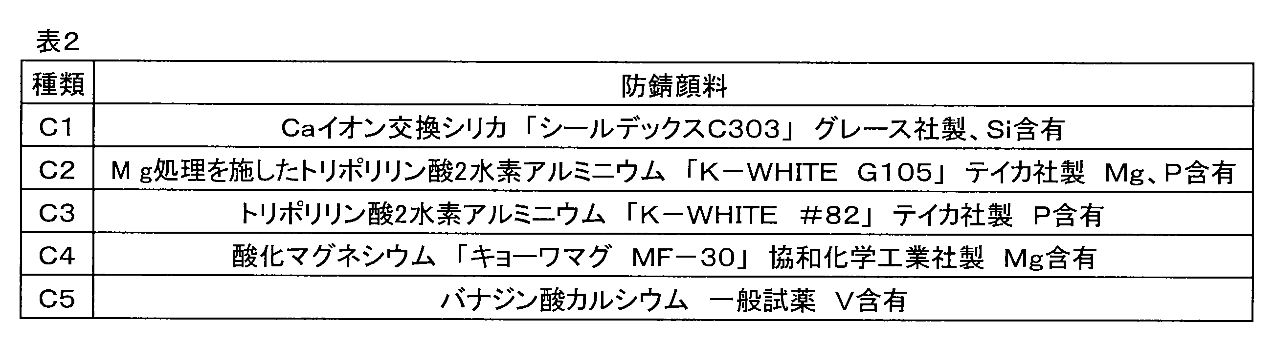
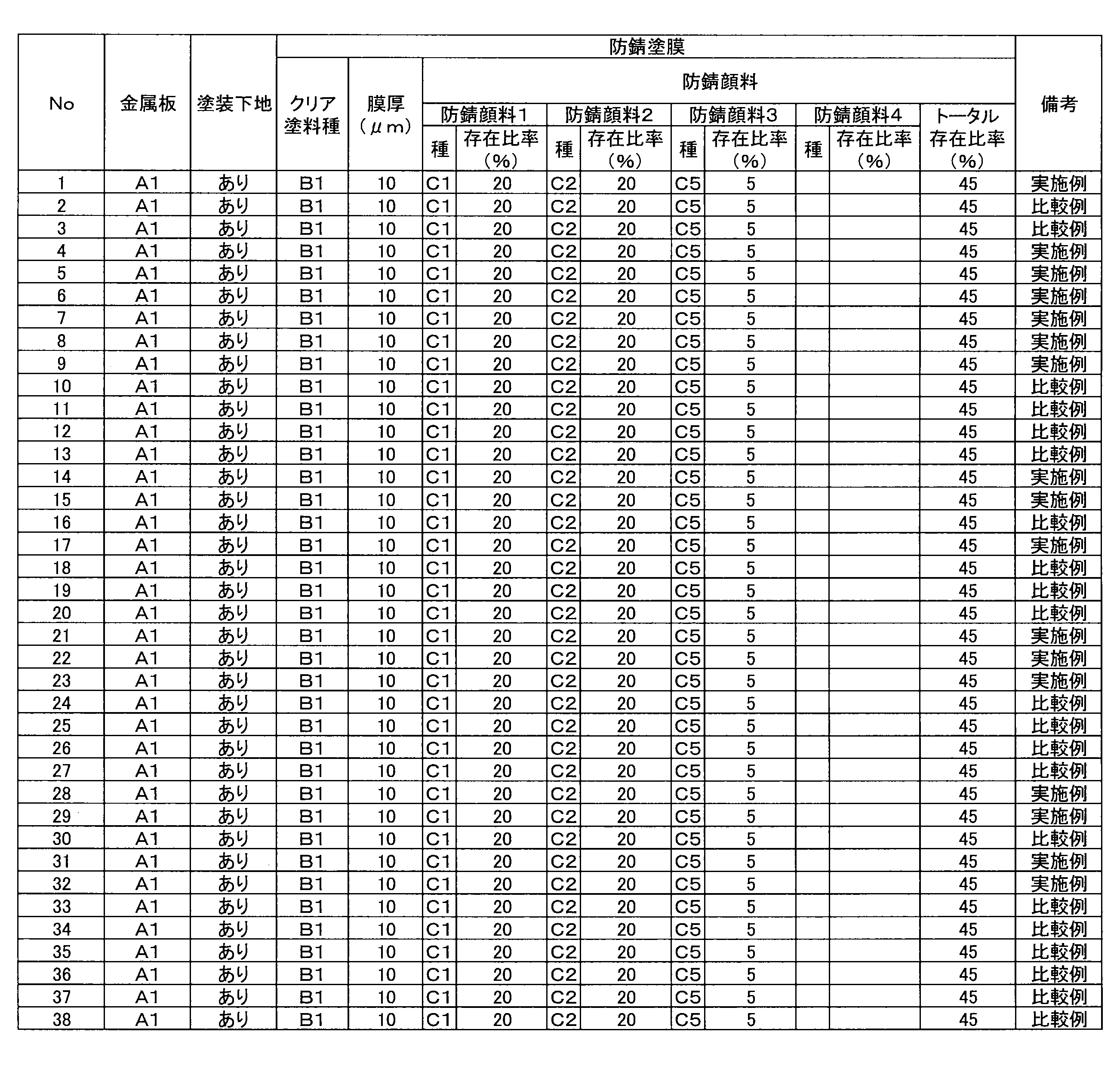
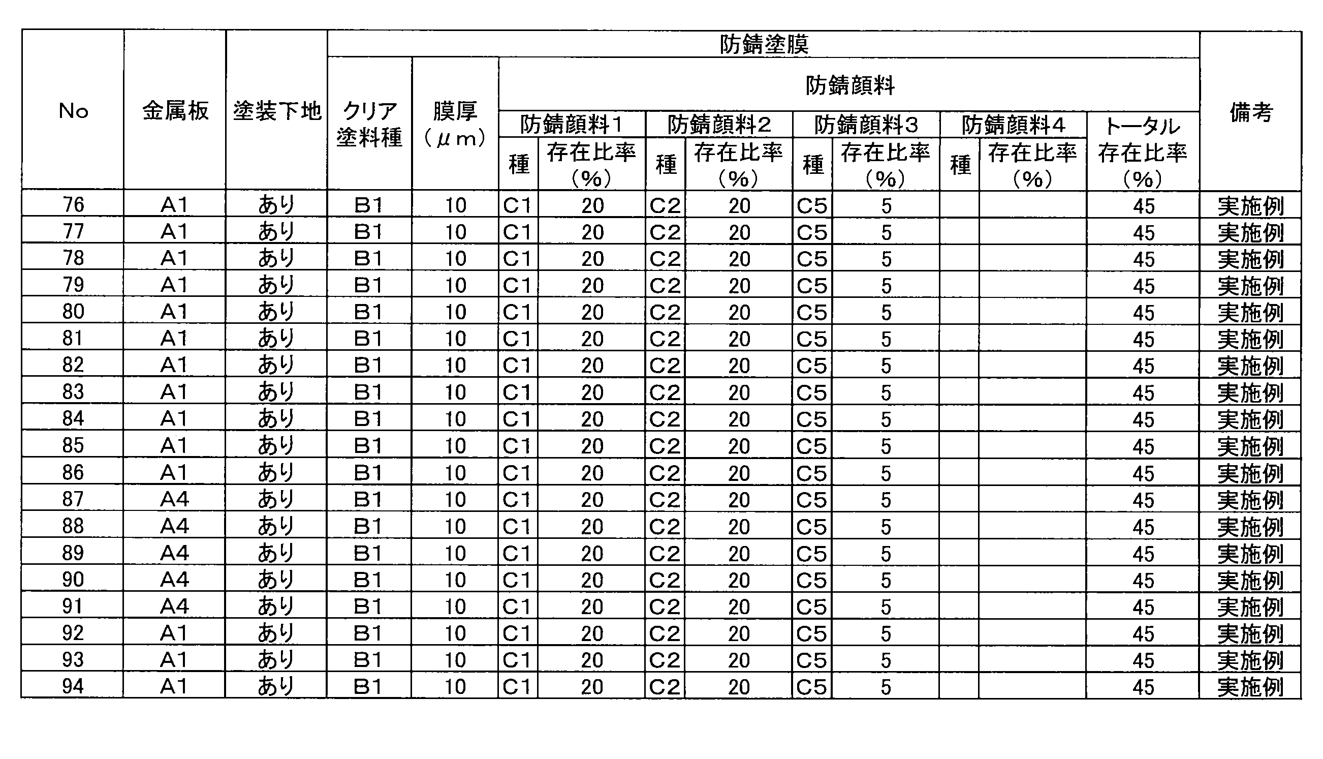
- the following clear anti-rust paints B1 to B3 not containing an anti-rust pigment were prepared by the following procedure, and then any one or more of the anti-rust pigments C1 to C5 listed in Table 2 were added and dispersed to prepare an anti-rust coating layer paint.
- the polyester resin and epoxy resin contained therein mainly functioned as a binder resin in the anti-rust coating layer.
- the polyester resin contained therein mainly functioned as a binder resin in the anti-rust coating layer.
- the polyester resin and urethane resin contained therein mainly functioned as a binder resin in the anti-rust coating layer.
- the prepared anti-rust paint was applied to one side of a plated steel sheet that had been subjected to a surface treatment using a bar coater, and then baked at a PMT (maximum steel sheet temperature) of 220°C ⁇ 10°C for a baking time of 10 seconds.
- PMT maximum steel sheet temperature
- the film thicknesses ( ⁇ m) of the anti-rust coating films are also shown in Tables 4-1 to 4-3.
- Table 2 "SHIELDEX” is a registered trademark, "K-WHITE” is a registered trademark, and "Kyowamag” is a registered trademark.
- Polyester resin (Vylon TM270, manufactured by Toyobo, "Vylon” is a registered trademark), epoxy resin (Epiclon TM1000, manufactured by DIC Corporation, “EPICLON” is a registered trademark), and melamine resin as a crosslinking agent (Cymel 327, manufactured by Allnex, “Cymel” is a registered trademark) were blended in a solid content ratio of 75:5:20, and an organic solvent (a mixture of cyclohexanone:Solvesso 150 in a mass ratio of 1:1 was used) was added to adjust the solid content concentration to 25 mass% to prepare this resin.
- an organic solvent a mixture of cyclohexanone:Solvesso 150 in a mass ratio of 1:1 was used
- ⁇ Clear anti-rust paint B2> Polyester resin (Vylon GK-140, manufactured by Toyobo) and a melamine resin as a crosslinking agent (Cymel 327, manufactured by Allnex) were blended in a solid content ratio of 80:20, and an organic solvent (a mixture of cyclohexanone:Solvesso 150 in a mass ratio of 1:1 was used) was added so that the solid content concentration was 25 mass% to prepare the resin.
- an organic solvent a mixture of cyclohexanone:Solvesso 150 in a mass ratio of 1:1 was used
- ⁇ Clear anti-rust paint B3> A polyester resin (Vylonal MD1480, manufactured by Toyobo, "Vylonal” is a registered trademark), a urethane resin (Superflex 150, manufactured by Dai-ichi Kogyo Seiyaku, “Superflex” is a registered trademark), and a melamine resin as a crosslinking agent (Cymel 327, manufactured by Allnex) were blended in a solids ratio of 40:40:20, and water was added to adjust the solids concentration to 25% by mass to prepare this resin.
- Vylonal MD1480 manufactured by Toyobo, "Vylonal” is a registered trademark
- Superflex 150 manufactured by Dai-ichi Kogyo Seiyaku
- Superflex a registered trademark
- a melamine resin as a crosslinking agent Cymel 327, manufactured by Allnex
- the paint used as the outermost coating layer was a commercially available polyester-based topcoat paint "FLC100HQ (white)" manufactured by Nippon Paint Co., Ltd., which was used as a binder resin.
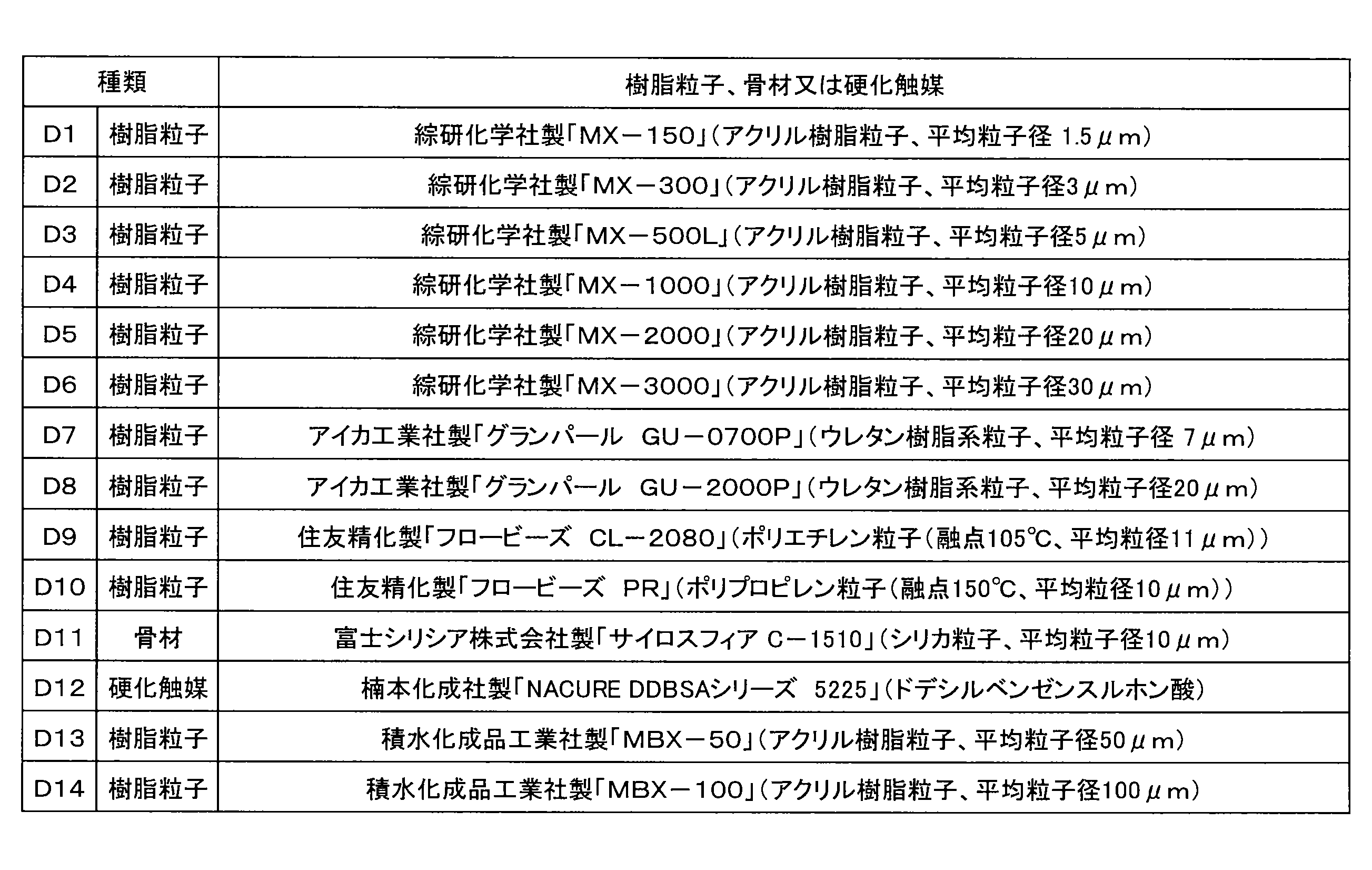
- This paint was prepared by adding a predetermined amount of one or more of the resin particles D1 to D10, D13 or D14, silica D11 as an aggregate, or curing catalyst D12, as shown in Table 3, and adjusting the amount.
- an organic solvent a mixture of cyclohexanone and Solvesso 150 at a mass ratio of 1:1 was used was added to adjust the viscosity.
- the prepared paint was applied to one side of a steel plate coated with a rust-preventive coating film using a curtain coater or a bar coater.
- a curtain coater after application with the curtain coater, baking was performed with a PMT (maximum steel plate temperature) of 230°C and a baking time of 40 seconds.
- a bar coater baking was performed with a PMT (maximum steel sheet temperature) of 230°C and a baking time of 12 seconds. For some samples, the baking time was changed while maintaining the PMT at 230°C.
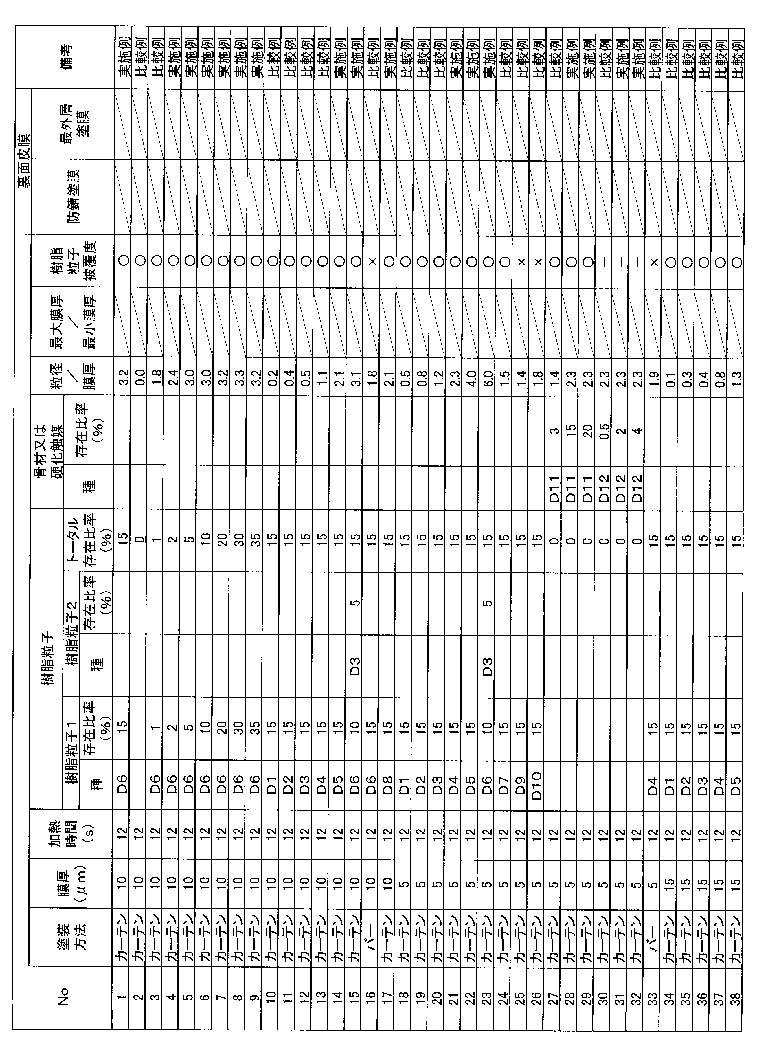
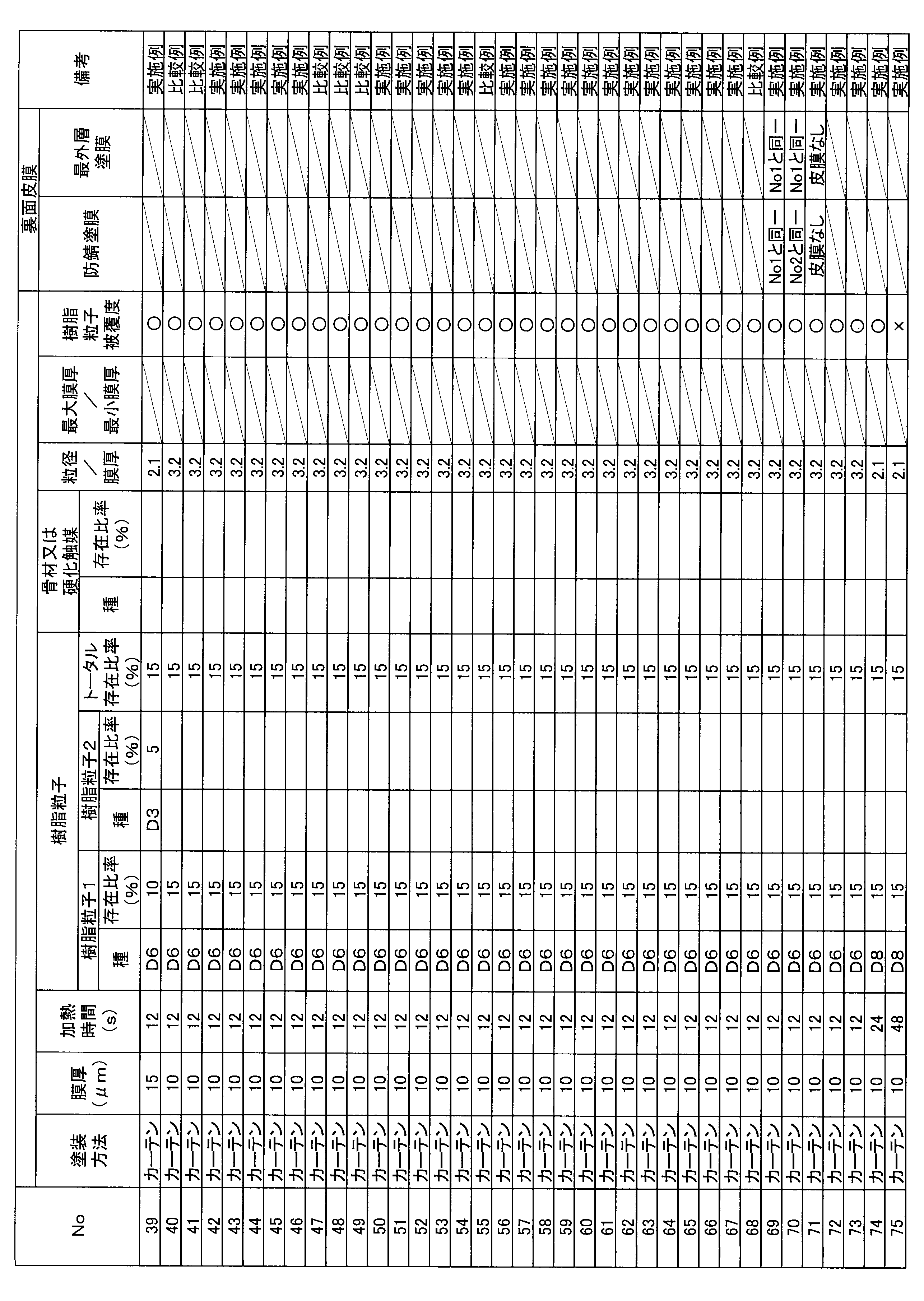
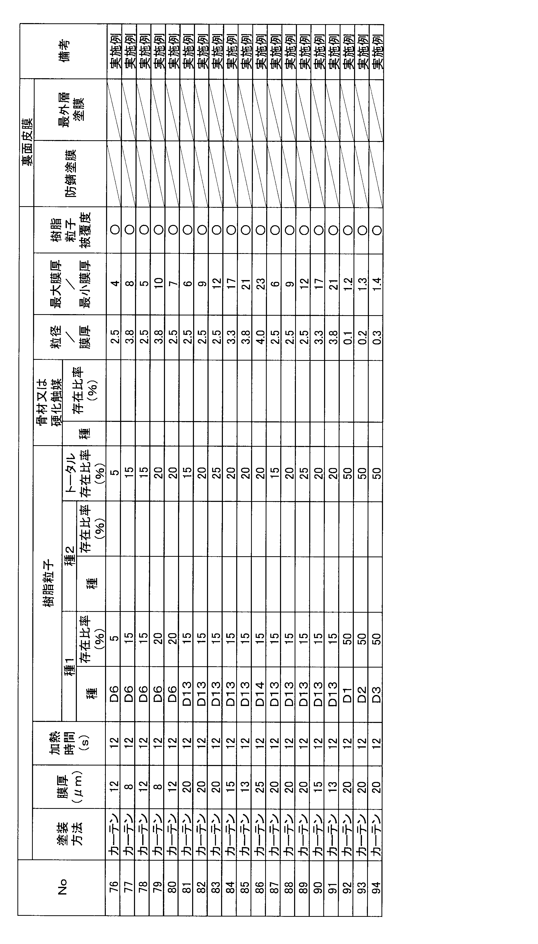
- the coating methods used are shown in Tables 5-1 to 5-3.
- the anti-rust coating film and the outermost coating film were applied to only the front surface, or to both the front surface and the back surface.
- the presence or absence and type of coating film on the back surface are shown in Table 5.
- Table 3 "Grand Pearl” is a registered trademark, and "Sylosphere” is a registered trademark.
- the respective resin particle abundance ratios (%) of the prepared outermost coating layers and the total abundance ratio (%) obtained by adding up the abundance ratios of all the resin particles contained therein are shown in Tables 5-1 to 5-3.
- the thickness T ( ⁇ m) of the outermost coating layer and the ratio (particle size/film thickness) of the average particle size ⁇ 10 to the average film thickness T are also shown in Tables 5-1 to 5-3.
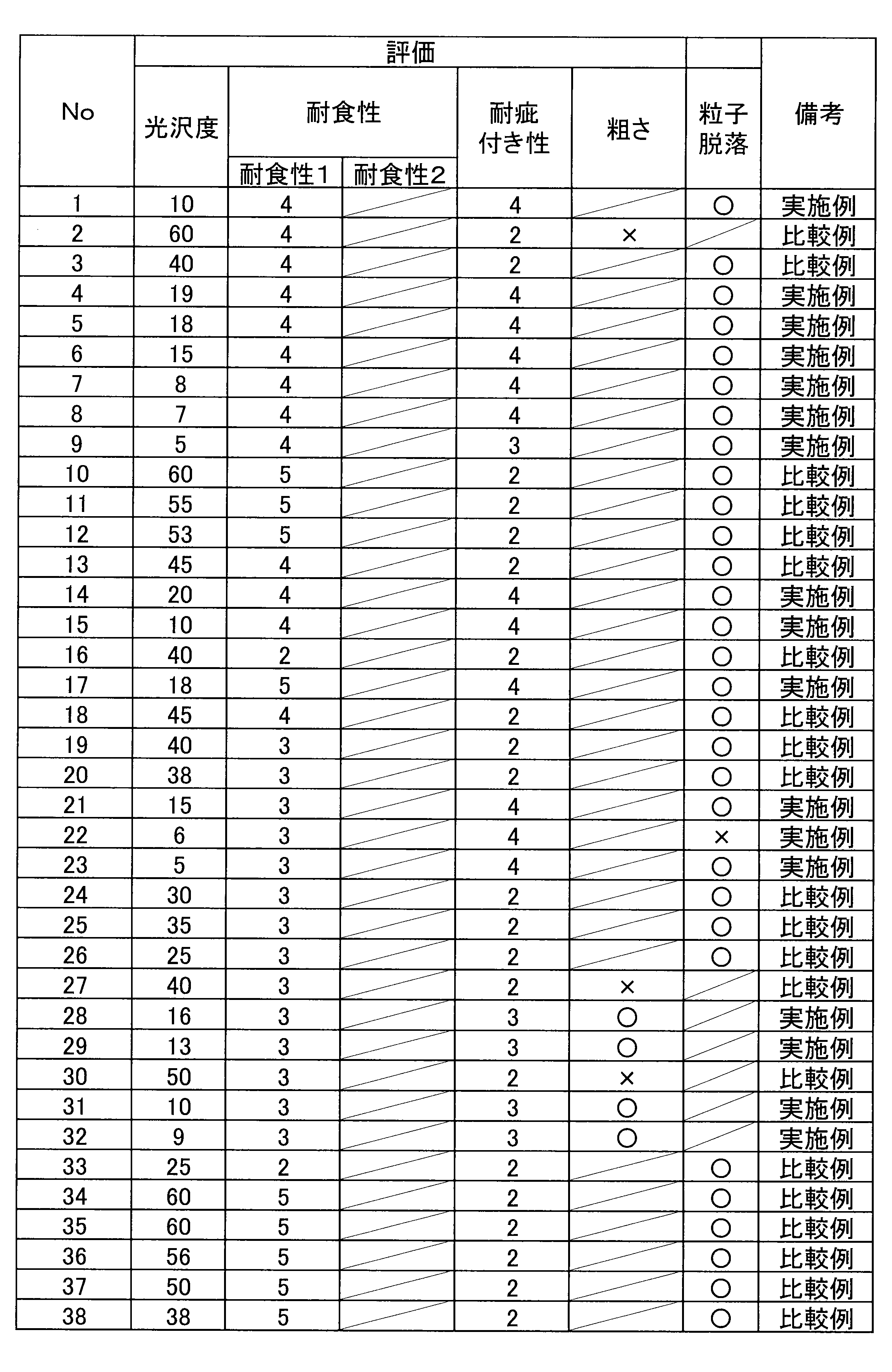
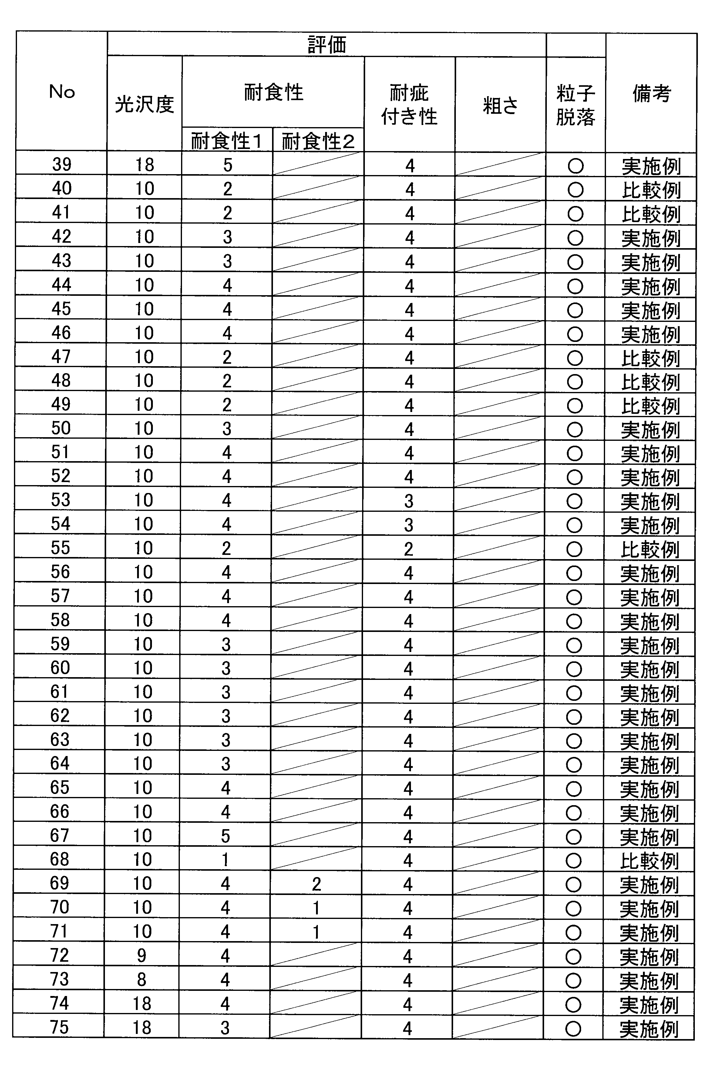
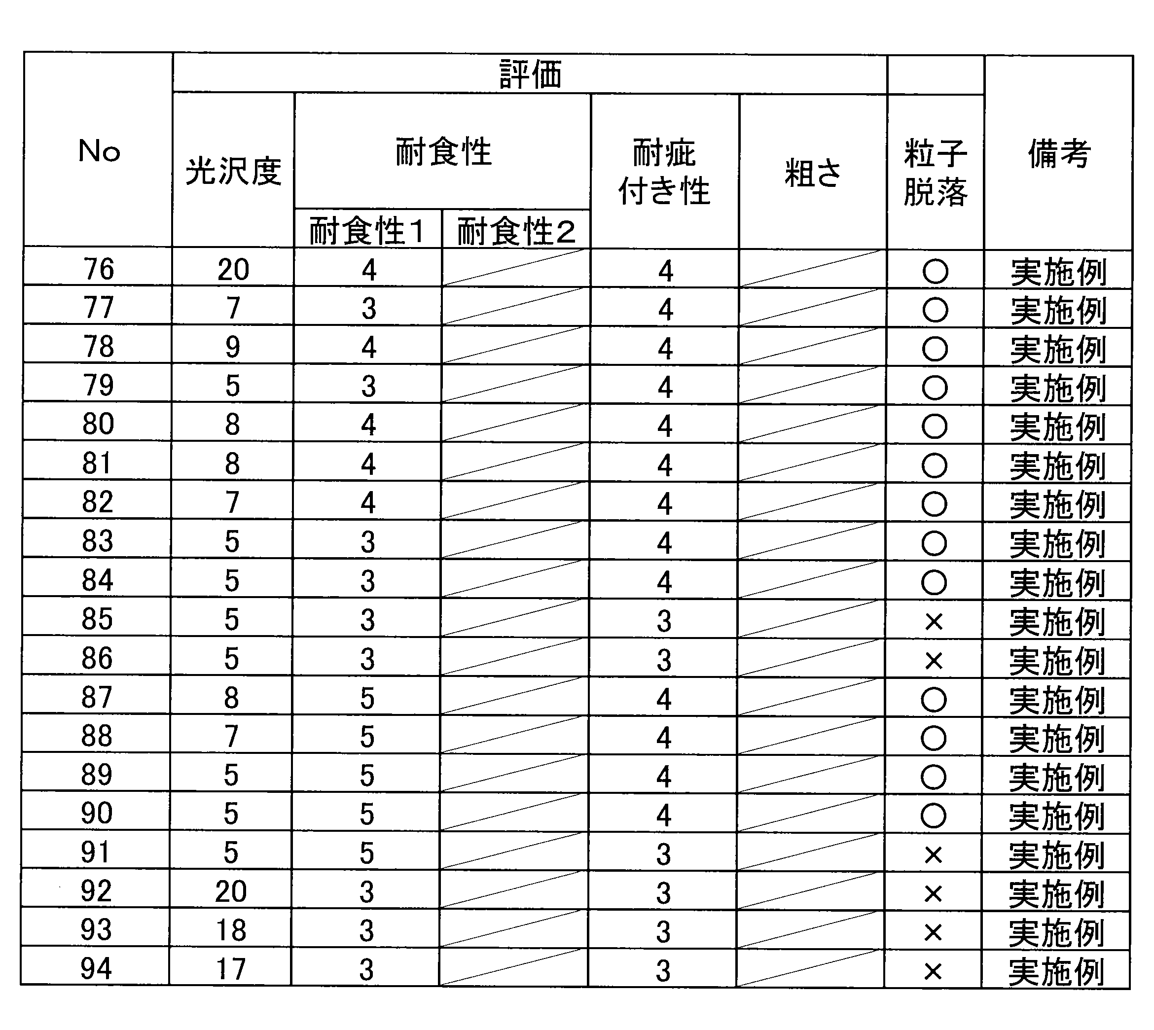
- the gloss (more specifically, the 60-degree specular gloss G S (60°)) of each of the obtained test materials was measured according to the method previously described, and the results are shown in Tables 6-1 to 6-3 below.
- Corrosion resistance 1 Regarding the corrosion resistance (corrosion resistance 1) on the coating surface, the end face of the surface-treated steel sheet was sealed with a seal tape, and a cross cut was made in the center of the test piece with a cutter, reaching the steel sheet base material. After 500 hours of salt spray (SST, 5% NaCl, 35°C atmosphere), the average coating blister width from the cut part was measured and calculated. The average coating blister width can be calculated by measuring the area of the coating blister part and then dividing it by the length of the cut part. The evaluation criteria are as follows. The pass level was 3 or higher.
- the test material had an anti-rust coating film and an outermost coating film formed on both the front and back sides.
- the average coating blister width from the left and right end faces (left: lower burr, right: upper burr) after 500 hours of salt spray (SST, 5% NaCl, 35°C atmosphere) was measured and calculated.
- the average coating blister width can be calculated by measuring the area of the coating blister and then dividing it by the end face length.
- the evaluation criteria are as follows. A score of 2 was determined to be the pass level. ⁇ Evaluation criteria> Rating 2: Average blister width is less than 5 mm and no red rust occurs. Rating 1: Average blister width is 5 mm or more, or red rust occurs.
- the scratch resistance of the coating surface was evaluated by a coin scratch test. A coin was placed in contact with the coating surface of the sample at a 45 degree angle and scratched with a load of 500 g. The scratches were evaluated according to the following criteria, with a pass level of 3 or higher. ⁇ Evaluation criteria> Rating 4: No coating peeling or very slight coating peeling was observed. 3: Slight peeling of the coating film was observed. 2: Partial peeling of the coating is observed. 1: The coating film is completely peeled off.
- the roughness (arithmetic mean roughness Ra) obtained from the surface of the coated steel plate was measured using a contact type roughness meter in accordance with JIS B 0601:2001.
- the measurement length was 8.0 mm, and the cutoff value was 0.8 mm.
- Ra of 2 ⁇ m or more was evaluated as ⁇ , and Ra of less than 2 ⁇ m was evaluated as ⁇ .
- test materials corresponding to the examples of the present invention are shown to be capable of achieving both an excellent low gloss matte appearance and high corrosion resistance. In addition, as a secondary effect, they are shown to exhibit high scratch resistance. Furthermore, the test materials corresponding to the configurations that satisfy the preferred aspects of the present invention are shown to exhibit the effect of suppressing particle shedding. On the other hand, the test materials corresponding to the comparative examples of the present invention failed at least either the low gloss or the corrosion resistance.
- No. 2 did not contain resin particles in the outermost coating layer, and No. 3 contained resin particles but at a low ratio.
- No. 27 did not contain resin particles in the outermost coating layer, but contained aggregate at a low ratio.
- No. 30 did not contain resin particles in the outermost coating layer, but contained curing catalyst at a low ratio. As a result, the gloss level was outside the range, and it is believed that the desired design could not be achieved.
- the ratio of the average particle diameter ⁇ 10 to the average film thickness T was less than twice that disclosed in the present application. Therefore, it is considered that the gloss level was outside the range, and the desired design could not be achieved.
- the thickness of the rust-preventive coating was less than 5 ⁇ m (see Table 4-1), and it is believed that the effect of inhibiting corrosion against corrosion factors that may penetrate through the thin film portion or the interface between the particles 101 and the binder resin 103 was insufficient. Therefore, it is believed that the desired corrosion resistance was not obtained.
- the thickness of the rust-preventive coating was more than 15 ⁇ m, and it is believed that painting defects occurred. Therefore, it is believed that the desired corrosion resistance was not obtained.
- the proportion of the rust-preventive pigment was less than 30% (see Table 4-1), and therefore it is believed that the effect of inhibiting corrosion against corrosion factors that may penetrate through the thin film portion or the interface between the particles 101 and the binder resin 103 was insufficient. Therefore, it is believed that the desired corrosion resistance was not obtained.
- the proportion of the rust-preventive pigment was more than 60% (see Table 4-1), and therefore it is believed that the adhesion between the rust-preventive coating layer 20 and the steel sheet 10, particularly in the processed portion, was insufficient. Therefore, it is believed that the desired corrosion resistance was not obtained.
- At least one side of a steel sheet having a Zn-containing plating layer It has two or more coating layers including an anti-rust coating layer,
- the 60 degree specular gloss GS(60 °) of the coating layer on at least one surface of the steel plate as defined in JIS Z 8741:1997 is 20% or less;
- the average thickness of the anticorrosive coating layer is 5 ⁇ m or more and 15 ⁇ m or less,
- the anticorrosive coating layer comprises a binder resin, a crosslinking agent, and an anticorrosive pigment;
- a coated steel sheet, wherein the ratio of the anti-rust pigment to the total area of the anti-rust coating film layer is, in terms of area ratio, 30% or more and 60% or less.
- the anti-rust pigment contains at least one of Si, P, Mg, and V.
- the Si includes at least one of calcium ion-exchanged silica and magnesium ion-exchanged silica
- the P includes at least one of zinc phosphate, magnesium dihydrogen phosphate, and aluminum dihydrogen tripolyphosphate
- the Mg includes at least one of magnesium dihydrogen phosphate, magnesium oxide, and magnesium hydroxide.
- the steel plate has, on the surface having a 60 degree specular gloss GS(60°) of 20% or less, the rust-preventive coating film layer as a lower layer of the two or more coating layers, and a colored coating film layer as an outermost layer located on the side furthest from the steel plate, the colored coating film layer containing resin particles, and a binder resin, a crosslinking agent, and a color pigment as film-forming components,
- the coated steel sheet according to any one of the above [1] to [3], wherein the average particle size of the resin particles is from 2 to 5 times the average film thickness of the outermost coating layer in a portion not containing the resin particles.
- the average particle size is a value obtained by measuring the circle equivalent diameters of the resin particles present in one observation field of view on the cross section, calculating the average of the two largest circle equivalent diameters among the circle equivalent diameters, and similarly averaging the average values obtained for any 10 observation fields of view by the number of fields of view.
Landscapes
- Chemical & Material Sciences (AREA)
- Organic Chemistry (AREA)
- Engineering & Computer Science (AREA)
- Chemical Kinetics & Catalysis (AREA)
- Materials Engineering (AREA)
- Mechanical Engineering (AREA)
- Metallurgy (AREA)
- Inorganic Chemistry (AREA)
- Wood Science & Technology (AREA)
- Life Sciences & Earth Sciences (AREA)
- Laminated Bodies (AREA)
- Health & Medical Sciences (AREA)
- Medicinal Chemistry (AREA)
- Polymers & Plastics (AREA)
- Application Of Or Painting With Fluid Materials (AREA)
- Other Surface Treatments For Metallic Materials (AREA)
Abstract
Description
かかる知見に基づき完成された本発明の要旨は、以下の通りである。
防錆塗膜層を含む2層以上の塗膜層を有し、
前記鋼板の少なくとも一方の面における前記塗膜層のJIS Z 8741:1997で規定される60度鏡面光沢度GS(60°)が、20%以下であり、
前記防錆塗膜層の平均膜厚は、5μm以上15μm以下であり、
前記防錆塗膜層は、バインダー樹脂、架橋剤、及び防錆顔料を含み、
前記塗膜層の任意の位置を厚み方向に切断した断面において、
前記防錆塗膜層の全面積に対する前記防錆顔料の存在比率が、面積率で、30%以上60%以下である、塗装鋼板。
[2]前記防錆顔料が、Si、P、Mg、及びVの少なくとも1種以上を含有する、上記[1]に記載の塗装鋼板。
[3]前記Siはカルシウムイオン交換シリカ又はマグネシウムイオン交換シリカのいずれか一つ以上を含み、前記Pはリン酸亜鉛、リン酸2水素マグネシウム又はトリポリリン酸2水素アルミニウムのいずれか一つ以上を含み、前記Mgはリン酸2水素マグネシウム、酸化マグネシウム又は水酸化マグネシウムのいずれか一つ以上を含む、上記[2]に記載の塗装鋼板。
[4]前記鋼板の前記60度鏡面光沢度GS(60°)が20%以下である前記面において、前記2層以上の塗膜層の下層において前記防錆塗膜層を有し、前記鋼板から最も遠い側に位置する最外層において着色塗膜層を有し、前記着色塗膜層は、樹脂粒子並びに、造膜成分としてのバインダー樹脂、架橋剤、及び着色顔料を含み、
前記断面において、
前記樹脂粒子の平均粒径が、前記最外層塗膜層の前記樹脂粒子を含有しない部分における平均膜厚に対して、2倍以上5倍以下である、上記[1]又は[2]に記載の塗装鋼板。
ただし、前記平均粒径は、前記断面における1つの観察視野領域において、前記観察視野領域中に存在している前記樹脂粒子の円相当直径を測定し、前記円相当直径のうち大きいものの順に上位2個の前記円相当直径の平均値を算出し、同様にして任意の10箇所の観察視野領域について得られた前記平均値を、更に視野数で平均することで得られる値とする。
[5]前記最外層塗膜層の全面積に対する前記樹脂粒子の存在比率が、面積率で、5%以上30%以下である、上記[4]に記載の塗装鋼板。
[6]前記断面において、
前記最外層塗膜層の前記樹脂粒子を含有しない前記部分における表面の位置から突出している前記樹脂粒子の突出部分は、前記突出部分の外周部に沿った長さの半分以上が、厚み0.5μm以上の前記造膜成分で覆われている、上記[4]に記載の塗装鋼板。
[7]前記樹脂粒子は、アクリル樹脂製の樹脂粒子である、上記[4]に記載の塗装鋼板。
[8]前記樹脂粒子は、アクリル樹脂製の樹脂粒子である、上記[5]に記載の塗装鋼板。
[9]前記樹脂粒子は、アクリル樹脂製の樹脂粒子である、上記[6]に記載の塗装鋼板。
[10]前記バインダー樹脂は、アクリル樹脂製又はポリエステル樹脂製のバインダー樹脂である、上記[4]に記載の塗装鋼板。
[11]前記バインダー樹脂は、アクリル樹脂製又はポリエステル樹脂製のバインダー樹脂である、上記[5]に記載の塗装鋼板。
[12]前記バインダー樹脂は、アクリル樹脂製又はポリエステル樹脂製のバインダー樹脂である、上記[6]に記載の塗装鋼板。
[13]前記バインダー樹脂は、アクリル樹脂製又はポリエステル樹脂製のバインダー樹脂である、上記[7]に記載の塗装鋼板。
[14]前記バインダー樹脂は、アクリル樹脂製又はポリエステル樹脂製のバインダー樹脂である、上記[8]に記載の塗装鋼板。
[15]前記バインダー樹脂は、アクリル樹脂製又はポリエステル樹脂製のバインダー樹脂である、上記[9]に記載の塗装鋼板。
[16]前記鋼板の前記60度鏡面光沢度GS(60°)が20%以下である前記面において、前記鋼板の表面粗さは、Raで2μm以上であること、又は、前記塗膜層は、シリカを含む顔料から構成される骨材を15%以上含有することの何れか1つ又は2つから選択される特徴を有する、上記[1]又は[2]に記載の塗装鋼板。
本実施形態に係る塗装鋼板1において、母材である鋼板10としては、各種の鋼板を用いることが可能である。このような鋼板の素材として、例えば、Alキルド鋼、Ti、Nb等を含有させた極低炭素鋼、極低炭素鋼にP、Si、Mn等の強化元素を更に含有させた高強度鋼等といった、種々の鋼板を用いること可能である。
本実施形態に係る塗装鋼板1において、鋼板10の表面に設けられる防錆塗膜層20について説明する。かかる防錆塗膜層20は、バインダー樹脂、架橋剤、及び防錆顔料を含有する樹脂皮膜層である。
本実施形態にかかる最外層塗膜層30は、図1A~図1Cに例示したように、塗膜11の最外層に位置し、粒子101が、造膜成分としてのバインダー樹脂103中に分散した状態で存在している樹脂皮膜層である。最外層塗膜層30は、上記の粒子101及びバインダー樹脂103に加えて、更に、架橋剤や着色剤等といった各種の添加剤を含有していてもよい。
本実施形態に係る最外層塗膜層30において、粒子101は、最外層塗膜層30の粒子101を含有しない部分における表面の位置から突出している。これにより、塗装鋼板1全体としてシボ外観とマット調外観とを兼ね備えた優れた意匠性を実現することができる。最外層塗膜層30と粒子101の関係の詳細については、後述する。
また、本実施形態に係る最外層塗膜層30が含有する、造膜成分としてのバインダー樹脂103は、粒子101のバインダーとして機能するものであれば、任意の素材を用いることが可能である。ただし、製造の簡便性及びコスト性の観点、並びに、耐食性及び耐疵付き性の観点から、バインダー樹脂103として、各種の有機樹脂を用いることが好ましい。このようなバインダー樹脂103として、例えば、アクリル系樹脂、ポリエステル系樹脂、ウレタン系樹脂、フッ素系樹脂等を挙げることができる。なかでも、アクリル系樹脂又はポリエステル系樹脂を主成分とするバインダー樹脂を用いることが、さらにより好ましい。
続いて、図2を参照しながら、本実施形態に係る最外層塗膜層30中における粒子101の分布状態について、詳細に説明する。図2は、本実施形態に係る塗装鋼板1における最外層塗膜層30について説明するための説明図である。
本実施形態に係る最外層塗膜層30における上記のような断面における粒子101の存在比率は、最外層塗膜層30に占める粒子101の面積割合である面積率の平均値(すなわち、平均面積率)で、5%以上30%以下の範囲内となっている。
本実施形態に係る最外層塗膜層30における、上記のような断面において、粒子101を含有しない部分での最外層塗膜層30の平均膜厚Tは、好ましくは、10μm以上である。また平均膜厚Tは、好ましくは、40μm以下である。断面における粒子101を含有しない部分での最外層塗膜層30の平均膜厚Tが10μm未満である場合には、最外層塗膜層30の厚みが薄すぎて、所望の耐食性を実現することができない。平均膜厚Tが10μm以上となることで、本実施形態に係る塗装鋼板1に求められる耐食性を実現することができる。平均膜厚Tは、より好ましくは12μm以上であり、さらにより好ましくは15μm以上である。
続いて、図2を参照しながら、最外層塗膜層30中における粒子101の存在状態について、詳細に説明する。図2は、本実施形態にかかる塗装鋼板1における最外層塗膜層30が有する粒子101について説明するための模式図である。
また、塗膜11の任意の位置を厚み方向に切断した断面において、最外層塗膜層30の樹脂粒子を含有しない部分における表面の位置から突出している粒子101の突出部分(以下、「突出部分P」という。)は、当該突出部分の外周部に沿った長さ(以下、「突出部分周長さL1」という。)の半分以上が、厚み0.5μm以上の造膜成分で覆われている。
粒子101の平均粒径φ10が上述の構成を備えるほか、粒子101の全部の平均粒径は、防錆塗膜の膜厚が10μmの場合、好ましくは、15μm以上である。また、粒子101の全部の平均粒径は、防錆塗膜の膜厚が10μmの場合、好ましくは、40μm以下である。粒子101の全部の平均粒径が、15μm未満である場合には、粒子101の平均粒径が小さすぎて、所望の意匠性、耐疵付き性を実現することができない。粒子101の全部の平均粒径が15μm以上となることで、本実施形態に係る塗装鋼板1に求められる意匠、耐疵付き性をより実現することができる。粒子101の平均粒径は、より好ましくは18μm以上であり、さらにより好ましくは20μm以上である。
本実施形態に係る最外層塗膜層30において、後述の手順で特定される最小膜厚Hminに対する最大膜厚HMAXの比(HMAX/Hmin)が、好ましくは、5以上20以下である。当該比(HMAX/Hmin)が上記範囲であることにより、最外層塗膜層30の60度鏡面光沢度GS(60°)の値をより好ましいものとすることができる。これにより、より優れたマット調外観(ひいては、より優れた意匠性)を示すこととなる。また、上記比(HMAX/Hmin)を5以上とすることにより、塗装鋼板1における当該表面の触感を好適なものとすることができる。かかる観点から、最大膜厚HMAXの比(HMAX/Hmin)は、より好ましくは6以上であり、さらにより好ましくは、7.5以上である。また、上記比(HMAX/Hmin)は、より好ましくは、17.5以下であり、さらにより好ましくは、15以下である。
最外層塗膜層30は、最外層塗膜層30の60度鏡面光沢度GS(60°)の値が20%以下となる限りにおいて、粒子101を含まないような所望の他の構成をとり得る。
続いて、本実施形態に係る塗装鋼板の製造方法の一例について説明する。
まず、母材となる鋼板に対して、アルカリ脱脂処理、水洗処理、酸洗処理等をはじめとする各種の前処理を施して、清浄な鋼板表面とする。
以下の表1に示す、A1~A5の5種類の鋼板を準備した(いずれも市販のものである。)。以下の表1において、めっき付着量は、片面あたりの付着量である。準備した鋼板に対して、クロメートフリー系塗装下地処理(CT-E300/日本パーカライジング社製と同等のもの)を60mg/m2施しためっき鋼板(板厚0.6mm)も準備した。塗装下地処理に用いた処理液は、その成分としてシランカップリング剤を含有するものであり、かかる塗装下地処理により形成される皮膜層は、塗装下地処理皮膜層として機能する。なお、塗装下地処理の有無は、以下の表4-1~4-3に記載した。
まず、防錆顔料を含まない下記のクリア防錆塗料B1~B3を以下の手順で作製し、その後表2に記載の防錆顔料C1~C5の何れか1つ又は2つ以上を添加、顔料分散することで防錆塗膜塗料を作製した。クリア防錆塗料B1を用いる場合は、これに含まれるポリエステル樹脂及びエポキシ樹脂が、主に防錆塗膜層におけるバインダー樹脂として機能する。クリア防錆塗料B2を用いる場合は、これに含まれるポリエステル樹脂が、主に防錆塗膜層におけるバインダー樹脂として機能する。クリア防錆塗料B3を用いる場合は、これに含まれるポリエステル樹脂及びウレタン樹脂が、主に防錆塗膜層におけるバインダー樹脂として機能する。作製した防錆塗料を用い、下地処理を施しためっき鋼板の片面にバーコーターで塗布した後、PMT(鋼板最高到達温度)が220℃±10℃、焼付け時間10秒で焼付けを行った。作製した防錆塗膜の防錆顔料C1~C5の種別及びそれぞれの存在比率(%)並びに、含まれる全ての防錆顔料の存在比率を足し合わせたトータル存在比率(%)を表4-1~4-3に記載した。また、防錆塗膜の膜厚(μm)を表4-1~4-3に記載した。表2で、「SHIELDEX」は登録商標であり、「K-WHITE」は登録商標であり、「Kyowamag\キョ-ワマグ」は登録商標である。
ポリエステル樹脂(バイロンTM270、東洋紡製、「バイロン」は登録商標である。)、エポキシ樹脂(エピクロンTM1000、DIC社製、「EPICLON」は登録商標である。)、架橋剤としてメラミン樹脂(サイメル327、allnex社製、「サイメル」は登録商標である。)を固形分比率で、75:5:20でブレンドし、固形分濃度が25質量%となるように有機溶剤(質量比でシクロヘキサノン:ソルベッソ150=1:1に混合したものを使用)を加え調整し作製した。
ポリエステル樹脂(バイロンGK-140、東洋紡製)、架橋剤としてメラミン樹脂(サイメル327、allnex社製)を固形分比率で、80:20でブレンドし、固形分濃度が25質量%となるように有機溶剤(質量比でシクロヘキサノン:ソルベッソ150=1:1に混合したものを使用)を加え調整し作製した。
ポリエステル樹脂(バイロナールMD1480、東洋紡製、「バイロナール」は登録商標である。)、ウレタン樹脂(スーパーフレックス150、第一工業製薬製、「スーパーフレックス」は登録商標である。)、架橋剤としてメラミン樹脂(サイメル327、allnex社製)を固形分比率で、40:40:20でブレンドし、固形分濃度が25質量%となるように水を加え調整し作製した。
最外層塗膜として使用した塗料は、バインダー樹脂として、市販のポリエステル系上塗り塗料である日本ペイント社製「FLC100HQ(白色系)」を用いた。この塗料に表3記載の樹脂粒子D1~D10、D13若しくはD14、骨材としてのシリカD11、または、硬化触媒D12の何れか1つ又は2つ以上を所定量添加し、調整し作製した。なお、作製した塗料の粘度に応じ、有機溶剤(質量比でシクロヘキサノン:ソルベッソ150=1:1に混合したものを使用)を加え粘度を調整した。作製した塗料を用い、防錆塗膜を塗布した鋼板の片面にカーテンコーター又はバーコーターで塗布した。カーテンコーターの場合、カーテンコーターで塗布した後、PMT(鋼板最高到達温度)が230℃、焼付け時間40秒で焼付けを行った。バーコーターの場合も同様に、PMT(鋼板最高到達温度)が230℃、焼付け時間12秒で焼付けを行った。一部サンプルにおいては、PMTは230℃で維持しつつ、焼付け時間を変更して行なった。使用した塗装方法を表5-1~表5-3に記載した。防錆塗膜及び最外層塗膜は、おもて面のみ、又は、おもて面及び裏面の両方に塗布した。裏面における塗膜の有無及び種別を表5に記載した。表3で、「グランパール」は登録商標であり、「Sylosphere\サイロスフェア」は登録商標である。
塗膜形成面における耐食性(耐食性1)について、表面処理鋼板の端面をシールテープし、試験片中央部に鋼板素地まで到達するクロスカットをカッターで付与した後、塩水噴霧(SST、5%NaCl、35℃雰囲気)500hr実施後のカット部からの平均塗膜膨れ幅を測定・算出した。なお、平均塗膜膨れ幅は、塗膜膨れ部の面積を計測後、カット部長さで除することより算出できる。また、評価基準は、以下の通りである。合格レベルは3以上とした。
<評価基準>
評点5:0.5mm未満で赤錆発生なし
4:0.5mm以上1mm未満で赤錆発生なし
3:1mm以上2mm未満で赤錆発生なし
2:2mm以上5mm未満で赤錆発生なし
1:5mm以上、または、赤錆発生
端面耐食性(耐食性2)について、おもて面及び裏面の両方に防錆塗膜及び最外層塗膜を形成した供試材において、表面処理鋼板の上下端面をシールテープした後、塩水噴霧(SST、5%NaCl、35℃雰囲気)500hr実施後の左右の端面部(左:下バリ、右:上バリ)からの平均塗膜膨れ幅を測定・算出した。なお、平均塗膜膨れ幅は、塗膜膨れ部の面積を計測後、端面部長さで除することより算出できる。また、評価基準は、以下の通りである。評点2を合格レベルとした。
<評価基準>
評点2:平均膨れ幅が5mm未満で赤錆発生なし
1:平均膨れ幅が5mm以上、または、赤錆発生
塗膜形成面における耐疵付き性について、コインスクラッチ試験により、耐疵付き性を評価した。作製したサンプルの塗装面に対し、硬貨を45度の角度で傾けた状態で接触させ、荷重を500gでスクラッチした。付与した疵を以下のような基準で評価し、合格レベルは3以上とした。
<評価基準>
評点4:塗膜剥離なし、または極僅かに塗膜剥離が認められる。
3:僅かに塗膜剥離が認められる。
2:部分的に塗膜剥離が認められる。
1:塗膜が完全に剥離している。
塗装鋼板の表面から得られる粗さ(算術平均粗さRa)は、JIS B 0601:2001に準拠して、接触式の粗さ計にて求めた。測定長さを8.0mmとし、カットオフ値を0.8mmとした。Raが2μm以上を〇とし、Raが2μm未満を×とした。
最外層塗膜層に樹脂粒子を含む試料において、試験面(塗装面)が外面になるように円筒絞り(絞り条件:ブランク径が100mmφ、パンチ径が50mmφ、ダイ径が52.4mmφ、しわ押え力(BHF)が1.5ton)した後、円筒絞り壁面の疵発生の有無を目視で確認した。疵発生が確認された疵発生部位に関しては、疵部を含む壁部を切り取り、表面SEM観察にて樹脂粒子の脱落が生じているか確認した。壁部に疵発生が確認されなかったもの、または、疵発生は確認されたものの樹脂粒子の脱落が生じていないものを〇とし、疵発生が確認され、樹脂粒子の脱落が生じていると確認されたものを×とした。


[1]Zn含有めっき層を有する鋼板上の少なくとも片面に、
防錆塗膜層を含む2層以上の塗膜層を有し、
前記鋼板の少なくとも一方の面における前記塗膜層のJIS Z 8741:1997で規定される60度鏡面光沢度GS(60°)が、20%以下であり、
前記防錆塗膜層の平均膜厚は、5μm以上15μm以下であり、
前記防錆塗膜層は、バインダー樹脂、架橋剤、及び防錆顔料を含み、
前記塗膜層の任意の位置を厚み方向に切断した断面において、
前記防錆塗膜層の全面積に対する前記防錆顔料の存在比率が、面積率で、30%以上60%以下である、塗装鋼板。
[2]前記防錆顔料が、Si、P、Mg、及びVの少なくとも1種以上を含有する、上記[1]に記載の塗装鋼板。
[3]前記Siはカルシウムイオン交換シリカ又はマグネシウムイオン交換シリカのいずれか一つ以上を含み、前記Pはリン酸亜鉛、リン酸2水素マグネシウム又はトリポリリン酸2水素アルミニウムのいずれか一つ以上を含み、前記Mgはリン酸2水素マグネシウム、酸化マグネシウム又は水酸化マグネシウムのいずれか一つ以上を含む、上記[2]に記載の塗装鋼板。
[4]前記鋼板の前記60度鏡面光沢度GS(60°)が20%以下である前記面において、前記2層以上の塗膜層の下層において前記防錆塗膜層を有し、前記鋼板から最も遠い側に位置する最外層において着色塗膜層を有し、前記着色塗膜層は、樹脂粒子並びに、造膜成分としてのバインダー樹脂、架橋剤、及び着色顔料を含み、
前記断面において、
前記樹脂粒子の平均粒径が、前記最外層塗膜層の前記樹脂粒子を含有しない部分における平均膜厚に対して、2倍以上5倍以下である、上記[1]~[3]のいずれか一つに記載の塗装鋼板。
ただし、前記平均粒径は、前記断面における1つの観察視野領域において、前記観察視野領域中に存在している前記樹脂粒子の円相当直径を測定し、前記円相当直径のうち大きいものの順に上位2個の前記円相当直径の平均値を算出し、同様にして任意の10箇所の観察視野領域について得られた前記平均値を、更に視野数で平均することで得られる値とする。
[5]前記最外層塗膜層の全面積に対する前記樹脂粒子の存在比率が、面積率で、5%以上30%以下である、上記[4]に記載の塗装鋼板。
[6]前記断面において、
前記最外層塗膜層の前記樹脂粒子を含有しない前記部分における表面の位置から突出している前記樹脂粒子の突出部分は、前記突出部分の外周部に沿った長さの半分以上が、厚み0.5μm以上の前記造膜成分で覆われている、上記[4]又は[5]に記載の塗装鋼板。
[7]前記樹脂粒子は、アクリル樹脂製の樹脂粒子である、上記[4]~[6]のいずれか一つに記載の塗装鋼板。
[8]前記バインダー樹脂は、アクリル樹脂製又はポリエステル樹脂製のバインダー樹脂である、上記[4]~[7]のいずれか一つに記載の塗装鋼板。
[9]前記鋼板の前記60度鏡面光沢度GS(60°)が20%以下である前記面において、前記鋼板の表面粗さは、Raで2μm以上であること、又は、前記塗膜層は、シリカを含む顔料から構成される骨材を15%以上含有することの何れか1つ又は2つから選択される特徴を有する、上記[1]~[8]のいずれか一つに記載の塗装鋼板。
10 鋼板
20 防錆塗膜層
30 最外層塗膜層
101 粒子
103 バインダー樹脂
Claims (10)
- Zn含有めっき層を有する鋼板上の少なくとも片面に、
防錆塗膜層を含む2層以上の塗膜層を有し、
前記鋼板の少なくとも一方の面における前記塗膜層のJIS Z 8741:1997で規定される60度鏡面光沢度GS(60°)が、20%以下であり、
前記防錆塗膜層の平均膜厚は、5μm以上15μm以下であり、
前記防錆塗膜層は、バインダー樹脂、架橋剤、及び防錆顔料を含み、
前記塗膜層の任意の位置を厚み方向に切断した断面において、
前記防錆塗膜層の全面積に対する前記防錆顔料の存在比率が、面積率で、30%以上60%以下である、塗装鋼板。 - 前記防錆顔料が、Si、P、Mg、及びVの少なくとも1種以上を含有する、請求項1に記載の塗装鋼板。
- 前記Siはカルシウムイオン交換シリカ又はマグネシウムイオン交換シリカのいずれか一つ以上を含み、前記Pはリン酸亜鉛、リン酸2水素マグネシウム又はトリポリリン酸2水素アルミニウムのいずれか一つ以上を含み、前記Mgはリン酸2水素マグネシウム、酸化マグネシウム又は水酸化マグネシウムのいずれか一つ以上を含む、請求項2に記載の塗装鋼板。
- 前記鋼板の前記60度鏡面光沢度GS(60°)が20%以下である前記面において、前記2層以上の塗膜層は、下層において前記防錆塗膜層を有し、前記鋼板から最も遠い側に位置する最外層において着色塗膜層を有し、前記着色塗膜層は、樹脂粒子並びに、造膜成分としてのバインダー樹脂、架橋剤、及び着色顔料を含み、
前記断面において、
前記樹脂粒子の平均粒径が、前記着色塗膜層の前記樹脂粒子を含有しない部分における平均膜厚に対して、2倍以上5倍以下である、請求項1に記載の塗装鋼板。
ただし、前記平均粒径は、前記断面における1つの観察視野領域において、前記観察視野領域中に存在している前記樹脂粒子の円相当直径を測定し、前記円相当直径のうち大きいものの順に上位2個の前記円相当直径の平均値を算出し、同様にして任意の10箇所の観察視野領域について得られた前記平均値を、更に視野数で平均することで得られる値とする。 - 前記着色塗膜層の全面積に対する前記樹脂粒子の存在比率が、面積率で、5%以上30%以下である、請求項4に記載の塗装鋼板。
- 前記断面において、
前記着色塗膜層の前記樹脂粒子を含有しない前記部分における表面の位置から突出している前記樹脂粒子の突出部分は、前記突出部分の外周部に沿った長さの半分以上が、厚み0.5μm以上の前記造膜成分で覆われている、請求項4に記載の塗装鋼板。 - 前記樹脂粒子は、アクリル樹脂製の樹脂粒子である、請求項4~6のいずれか一項に記載の塗装鋼板。
- 前記バインダー樹脂は、アクリル樹脂製又はポリエステル樹脂製のバインダー樹脂である、請求項4~6のいずれか一項に記載の塗装鋼板。
- 前記バインダー樹脂は、アクリル樹脂製又はポリエステル樹脂製のバインダー樹脂である、請求項7に記載の塗装鋼板。
- 前記鋼板の前記60度鏡面光沢度GS(60°)が20%以下である前記面において、前記鋼板の表面粗さは、Raで2μm以上であること、又は、前記塗膜層は、シリカを含む顔料から構成される骨材を15%以上含有することの何れか1つ又は2つから選択される特徴を有する、請求項1又は2に記載の塗装鋼板。
Priority Applications (5)
| Application Number | Priority Date | Filing Date | Title |
|---|---|---|---|
| EP24836076.0A EP4741153A1 (en) | 2023-07-03 | 2024-07-03 | Coated steel sheet |
| KR1020267001951A KR20260028048A (ko) | 2023-07-03 | 2024-07-03 | 도장 강판 |
| JP2025531580A JPWO2025009563A1 (ja) | 2023-07-03 | 2024-07-03 | |
| CN202480042346.XA CN121368526A (zh) | 2023-07-03 | 2024-07-03 | 涂装钢板 |
| MX2025015831A MX2025015831A (es) | 2023-07-03 | 2025-12-19 | Lamina de acero pintada |
Applications Claiming Priority (2)
| Application Number | Priority Date | Filing Date | Title |
|---|---|---|---|
| JP2023-109649 | 2023-07-03 | ||
| JP2023109649 | 2023-07-03 |
Publications (1)
| Publication Number | Publication Date |
|---|---|
| WO2025009563A1 true WO2025009563A1 (ja) | 2025-01-09 |
Family
ID=94171750
Family Applications (1)
| Application Number | Title | Priority Date | Filing Date |
|---|---|---|---|
| PCT/JP2024/024107 Ceased WO2025009563A1 (ja) | 2023-07-03 | 2024-07-03 | 塗装鋼板 |
Country Status (7)
| Country | Link |
|---|---|
| EP (1) | EP4741153A1 (ja) |
| JP (1) | JPWO2025009563A1 (ja) |
| KR (1) | KR20260028048A (ja) |
| CN (1) | CN121368526A (ja) |
| MX (1) | MX2025015831A (ja) |
| TW (1) | TWI903611B (ja) |
| WO (1) | WO2025009563A1 (ja) |
Citations (8)
| Publication number | Priority date | Publication date | Assignee | Title |
|---|---|---|---|---|
| JPH08183928A (ja) * | 1994-12-29 | 1996-07-16 | Nkk Corp | 耐摩耗性に優れた塗料組成物および塗装金属板 |
| JP2000192254A (ja) * | 1998-12-22 | 2000-07-11 | Sumitomo Metal Ind Ltd | 耐傷付き性に優れた高加工性塗装鋼板とその製造方法 |
| JP2004209974A (ja) * | 2002-12-16 | 2004-07-29 | Nippon Steel Corp | 意匠性に優れた塗装金属板及びその製造方法 |
| JP2009119360A (ja) * | 2007-11-14 | 2009-06-04 | Nippon Fine Coatings Inc | 塗装鋼板及び鋼板の塗装方法 |
| WO2012133671A1 (ja) * | 2011-03-29 | 2012-10-04 | 新日本製鐵株式会社 | 表面処理鋼板及びその製造方法 |
| WO2014112544A1 (ja) | 2013-01-17 | 2014-07-24 | 新日鐵住金株式会社 | 有機被覆亜鉛系めっき鋼板及びその製造方法 |
| JP2020142373A (ja) * | 2019-03-04 | 2020-09-10 | 日鉄日新製鋼株式会社 | 塗装金属板およびその製造方法 |
| JP2020157246A (ja) * | 2019-03-27 | 2020-10-01 | 日鉄日新製鋼株式会社 | 塗装金属板および塗装金属板の製造方法 |
Family Cites Families (1)
| Publication number | Priority date | Publication date | Assignee | Title |
|---|---|---|---|---|
| CN111683811B (zh) * | 2018-05-25 | 2022-06-14 | 日本制铁株式会社 | 表面处理钢板 |
-
2024
- 2024-07-03 TW TW113124837A patent/TWI903611B/zh active
- 2024-07-03 JP JP2025531580A patent/JPWO2025009563A1/ja active Pending
- 2024-07-03 CN CN202480042346.XA patent/CN121368526A/zh active Pending
- 2024-07-03 EP EP24836076.0A patent/EP4741153A1/en active Pending
- 2024-07-03 WO PCT/JP2024/024107 patent/WO2025009563A1/ja not_active Ceased
- 2024-07-03 KR KR1020267001951A patent/KR20260028048A/ko active Pending
-
2025
- 2025-12-19 MX MX2025015831A patent/MX2025015831A/es unknown
Patent Citations (8)
| Publication number | Priority date | Publication date | Assignee | Title |
|---|---|---|---|---|
| JPH08183928A (ja) * | 1994-12-29 | 1996-07-16 | Nkk Corp | 耐摩耗性に優れた塗料組成物および塗装金属板 |
| JP2000192254A (ja) * | 1998-12-22 | 2000-07-11 | Sumitomo Metal Ind Ltd | 耐傷付き性に優れた高加工性塗装鋼板とその製造方法 |
| JP2004209974A (ja) * | 2002-12-16 | 2004-07-29 | Nippon Steel Corp | 意匠性に優れた塗装金属板及びその製造方法 |
| JP2009119360A (ja) * | 2007-11-14 | 2009-06-04 | Nippon Fine Coatings Inc | 塗装鋼板及び鋼板の塗装方法 |
| WO2012133671A1 (ja) * | 2011-03-29 | 2012-10-04 | 新日本製鐵株式会社 | 表面処理鋼板及びその製造方法 |
| WO2014112544A1 (ja) | 2013-01-17 | 2014-07-24 | 新日鐵住金株式会社 | 有機被覆亜鉛系めっき鋼板及びその製造方法 |
| JP2020142373A (ja) * | 2019-03-04 | 2020-09-10 | 日鉄日新製鋼株式会社 | 塗装金属板およびその製造方法 |
| JP2020157246A (ja) * | 2019-03-27 | 2020-10-01 | 日鉄日新製鋼株式会社 | 塗装金属板および塗装金属板の製造方法 |
Also Published As
| Publication number | Publication date |
|---|---|
| TWI903611B (zh) | 2025-11-01 |
| CN121368526A (zh) | 2026-01-20 |
| EP4741153A1 (en) | 2026-05-13 |
| MX2025015831A (es) | 2026-02-03 |
| KR20260028048A (ko) | 2026-03-03 |
| TW202508828A (zh) | 2025-03-01 |
| JPWO2025009563A1 (ja) | 2025-01-09 |
Similar Documents
| Publication | Publication Date | Title |
|---|---|---|
| US6465114B1 (en) | -Zn coated steel material, ZN coated steel sheet and painted steel sheet excellent in corrosion resistance, and method of producing the same | |
| JP6680412B1 (ja) | 表面処理鋼板 | |
| TWI633205B (zh) | Method for manufacturing coated metal sheets and exterior building materials | |
| KR20170041766A (ko) | 도장 금속판, 그 제조 방법 및 외장 건재 | |
| JPWO2007013232A1 (ja) | プレコート金属板及びその製造方法 | |
| JP7143786B2 (ja) | 塗装金属板およびその製造方法 | |
| JP6772943B2 (ja) | 塗装鋼板 | |
| JP2010247347A (ja) | プレコート冷延鋼板およびこの製造方法 | |
| TWI903611B (zh) | 塗裝鋼板 | |
| JP2007119858A (ja) | クロムフリープレコート鋼板 | |
| JP3477174B2 (ja) | 非クロメート型表面処理金属板とその製造方法 | |
| JP7832576B2 (ja) | 塗装金属板 | |
| TWI906936B (zh) | 預塗覆鋼板 | |
| JPH0813156A (ja) | 高端面耐食性の着色潤滑処理亜鉛系めっき鋼板とその製法 | |
| JPH08120461A (ja) | 耐食性および電着塗装性に優れた有機複合被覆鋼板 | |
| JP2862208B1 (ja) | 耐疵付き性に優れた塗装金属板 | |
| JP5309648B2 (ja) | 塗装済み金属部材 | |
| JP2972126B2 (ja) | 着色化潤滑処理鋼板およびその製造法 | |
| JP2025161754A (ja) | プレコート金属板、部材及び表面処理金属板 | |
| JP2007289889A (ja) | 耐食性に優れた塗装鋼板 | |
| JP4983305B2 (ja) | 塗装鋼板、加工品及び薄型テレビ用パネル | |
| JP2005206921A (ja) | 非クロメート型表面処理金属板 | |
| JP6796100B2 (ja) | 被覆めっき鋼板 | |
| JPH0760897A (ja) | 潤滑性黒色鋼板 | |
| JPH07126826A (ja) | 重量シャッター用プレコート塗装鋼板 |
Legal Events
| Date | Code | Title | Description |
|---|---|---|---|
| 121 | Ep: the epo has been informed by wipo that ep was designated in this application |
Ref document number: 24836076 Country of ref document: EP Kind code of ref document: A1 |
|
| ENP | Entry into the national phase |
Ref document number: 2025531580 Country of ref document: JP Kind code of ref document: A |
|
| WWE | Wipo information: entry into national phase |
Ref document number: 2025531580 Country of ref document: JP |
|
| WWE | Wipo information: entry into national phase |
Ref document number: MX/A/2025/015831 Country of ref document: MX |
|
| WWE | Wipo information: entry into national phase |
Ref document number: 2501008849 Country of ref document: TH |
|
| WWE | Wipo information: entry into national phase |
Ref document number: 202617000813 Country of ref document: IN |
|
| WWP | Wipo information: published in national office |
Ref document number: 202617000813 Country of ref document: IN |
|
| ENP | Entry into the national phase |
Ref document number: 1020267001951 Country of ref document: KR Free format text: ST27 STATUS EVENT CODE: A-0-1-A10-A15-NAP-PA0105 (AS PROVIDED BY THE NATIONAL OFFICE) |
|
| WWE | Wipo information: entry into national phase |
Ref document number: 1020267001951 Country of ref document: KR |
|
| WWE | Wipo information: entry into national phase |
Ref document number: 2024836076 Country of ref document: EP |
|
| WWP | Wipo information: published in national office |
Ref document number: MX/A/2025/015831 Country of ref document: MX |
|
| NENP | Non-entry into the national phase |
Ref country code: DE |
|
| ENP | Entry into the national phase |
Ref document number: 2024836076 Country of ref document: EP Effective date: 20260203 |
|
| WWP | Wipo information: published in national office |
Ref document number: 1020267001951 Country of ref document: KR |
|
| WWP | Wipo information: published in national office |
Ref document number: 2024836076 Country of ref document: EP |