WO2025009374A1 - GaNエピタキシャル膜の製造方法及び半導体デバイスの製造方法 - Google Patents
GaNエピタキシャル膜の製造方法及び半導体デバイスの製造方法 Download PDFInfo
- Publication number
- WO2025009374A1 WO2025009374A1 PCT/JP2024/021963 JP2024021963W WO2025009374A1 WO 2025009374 A1 WO2025009374 A1 WO 2025009374A1 JP 2024021963 W JP2024021963 W JP 2024021963W WO 2025009374 A1 WO2025009374 A1 WO 2025009374A1
- Authority
- WO
- WIPO (PCT)
- Prior art keywords
- layer
- gan
- epitaxial film
- substrate
- gan epitaxial
- Prior art date
- Legal status (The legal status is an assumption and is not a legal conclusion. Google has not performed a legal analysis and makes no representation as to the accuracy of the status listed.)
- Ceased
Links
Images

Classifications
-
- H—ELECTRICITY
- H10—SEMICONDUCTOR DEVICES; ELECTRIC SOLID-STATE DEVICES NOT OTHERWISE PROVIDED FOR
- H10P—GENERIC PROCESSES OR APPARATUS FOR THE MANUFACTURE OR TREATMENT OF DEVICES COVERED BY CLASS H10
- H10P14/00—Formation of materials, e.g. in the shape of layers or pillars
- H10P14/20—Formation of materials, e.g. in the shape of layers or pillars of semiconductor materials
- H10P14/34—Deposited materials, e.g. layers
- H10P14/3402—Deposited materials, e.g. layers characterised by the chemical composition
- H10P14/3414—Deposited materials, e.g. layers characterised by the chemical composition being group IIIA-VIA materials
- H10P14/3416—Nitrides
-
- C—CHEMISTRY; METALLURGY
- C30—CRYSTAL GROWTH
- C30B—SINGLE-CRYSTAL GROWTH; UNIDIRECTIONAL SOLIDIFICATION OF EUTECTIC MATERIAL OR UNIDIRECTIONAL DEMIXING OF EUTECTOID MATERIAL; REFINING BY ZONE-MELTING OF MATERIAL; PRODUCTION OF A HOMOGENEOUS POLYCRYSTALLINE MATERIAL WITH DEFINED STRUCTURE; SINGLE CRYSTALS OR HOMOGENEOUS POLYCRYSTALLINE MATERIAL WITH DEFINED STRUCTURE; AFTER-TREATMENT OF SINGLE CRYSTALS OR A HOMOGENEOUS POLYCRYSTALLINE MATERIAL WITH DEFINED STRUCTURE; APPARATUS THEREFOR
- C30B25/00—Single-crystal growth by chemical reaction of reactive gases, e.g. chemical vapour-deposition growth
- C30B25/02—Epitaxial-layer growth
- C30B25/18—Epitaxial-layer growth characterised by the substrate
-
- C—CHEMISTRY; METALLURGY
- C30—CRYSTAL GROWTH
- C30B—SINGLE-CRYSTAL GROWTH; UNIDIRECTIONAL SOLIDIFICATION OF EUTECTIC MATERIAL OR UNIDIRECTIONAL DEMIXING OF EUTECTOID MATERIAL; REFINING BY ZONE-MELTING OF MATERIAL; PRODUCTION OF A HOMOGENEOUS POLYCRYSTALLINE MATERIAL WITH DEFINED STRUCTURE; SINGLE CRYSTALS OR HOMOGENEOUS POLYCRYSTALLINE MATERIAL WITH DEFINED STRUCTURE; AFTER-TREATMENT OF SINGLE CRYSTALS OR A HOMOGENEOUS POLYCRYSTALLINE MATERIAL WITH DEFINED STRUCTURE; APPARATUS THEREFOR
- C30B29/00—Single crystals or homogeneous polycrystalline material with defined structure characterised by the material or by their shape
- C30B29/10—Inorganic compounds or compositions
- C30B29/38—Nitrides
-
- H—ELECTRICITY
- H10—SEMICONDUCTOR DEVICES; ELECTRIC SOLID-STATE DEVICES NOT OTHERWISE PROVIDED FOR
- H10P—GENERIC PROCESSES OR APPARATUS FOR THE MANUFACTURE OR TREATMENT OF DEVICES COVERED BY CLASS H10
- H10P14/00—Formation of materials, e.g. in the shape of layers or pillars
- H10P14/20—Formation of materials, e.g. in the shape of layers or pillars of semiconductor materials
- H10P14/29—Formation of materials, e.g. in the shape of layers or pillars of semiconductor materials characterised by the substrates
Definitions
- the present invention relates to a method for manufacturing a GaN epitaxial film and a method for manufacturing a semiconductor device.
- Si, GaAs, and Sap (sapphire) bulk substrates are promising substrates for forming GaN epitaxial films because they can be obtained with large diameter substrates and are inexpensive, but when attempting to grow a thick epitaxial film to reduce dislocations in the epitaxial film, problems arise with substrate warping and cracks. Furthermore, attempts to overcome this make the buffer process extremely complicated, lowering productivity.
- GaN and AlN bulk substrate systems which have similar thermal expansion coefficients and lattice constants, are promising in terms of physical properties, but they cannot be mass-produced with a diameter of 150 mm or more and are expensive.
- Patent Document 1 there is a method of creating a GaN film with low dislocation density on a heterogeneous substrate using the VAS (Void-Assisted Separation) method and using this as a substrate, but it is unclear whether it can be made into a large diameter, and the process is complicated.
- Non-Patent Document 1 there is an example of GaN on Si substrates having a high defect density, which is improved by using GaN on GaN, but it is unclear whether it can be made into a large diameter.
- a vertical transistor can be produced by separating the support substrate including the ceramic core by ion implantation as described in Patent Document 4.
- an ultraviolet emitting element can be produced by separating the support substrate including the ceramic core by etching the planarizing layer ( SiO2 layer) as described in Patent Document 5.
- Patent Documents 4 and 6 disclose that, in addition to Si, SiC, AlN, AlGaN, Al2O3 , and the like can be used as the single crystal layer on the support substrate containing a ceramic core, and that those having similar lattice constants are preferable, but do not disclose whether the dislocation density can be reduced.
- ELO Epitaxial Lateral Overgrowth
- Patent Documents 7 and 8 describe ELO growth using island-shaped SiN on the support substrate of Patent Document 2.
- Patent Documents 9 and 10 describe the concept of growing GaN in two-stage island-like growth on a Si-containing film containing island-shaped SiN and then growing it by ELO to reduce dislocations, and describe the Si (doping) concentration of the two-stage island-shaped growth portion of GaN being 1.0 ⁇ 10 17 to 10 20 /cm 3 .
- Patent Document 11 describes that no mask such as SiN is used, and that island-shaped GaN is created under growth conditions to reduce dislocations by ELO growth, and describes that a GaN film with a TD (threading dislocation) density of 5.0 x 10 / cm can be obtained in one step, and 5.0 x 10 / cm in three steps.
- a known method for reducing dislocation density is to form a film composed of inclined planes as an underlayer, rather than growing the (0001) plane along which dislocations from below tend to propagate.
- This method uses a mask such as island-shaped SiN (Patent Document 1, Patent Documents 12-13), or grows an inclined plane film by adjusting the growth conditions without patterning a mask layer (Patent Documents 14-17).
- the substrate used is a free-standing GaN substrate that has been fabricated by the VAS method on a substrate such as Si, GaAs, or Sap. However, it is unclear whether it is possible to increase the diameter.
- the present invention has been made to solve the above problems, and has an object to provide a method for manufacturing a GaN epitaxial film that produces a GaN thick film that is large in diameter but free of warping or cracks and has a dislocation density of 1.0 ⁇ 10 6 /cm 2 or less, at low cost, through a simple process.
- Another object of the present invention is to provide a method for manufacturing semiconductor devices that can produce high-quality semiconductor devices at low cost.
- the present invention has been made to achieve the above-mentioned object, and provides a method for producing a GaN epitaxial film, comprising the steps of: a preparation step of preparing a support substrate having a diameter of 150 mm or more and a thickness of less than 1 mm, the support substrate having a core made of nitride ceramic sealed with a sealing layer; a substrate production step of sequentially laminating a planarizing layer and a seed crystal layer made of a SiC single crystal on the support substrate to obtain a substrate for epitaxial growth; and an epitaxial step of growing a GaN epitaxial film having a thickness of 7 ⁇ m or more on the substrate for epitaxial growth, thereby producing the GaN epitaxial film having a dislocation density of 1.0 ⁇ 10 6 /cm 2 or less.
- This method of manufacturing GaN epitaxial films allows the growth of GaN epitaxial films on an epitaxial growth substrate containing a ceramic core, making it possible to manufacture thick GaN films, unlike bulk substrates such as Si, Sap, and GaAs, which are inexpensive and have large diameter products but on which thick GaN epitaxial films cannot be formed due to differences in thermal expansion coefficients. Furthermore, if such thick films with low dislocations can be manufactured, the crystallinity of the device layer will be good, improving the breakdown voltage and reducing leakage current in electronic devices, and in visible and ultraviolet light devices, higher output or higher efficiency can be achieved, contributing to energy savings.
- the single crystal layer on the support substrate is made into a SiC single crystal.
- SiC is a material whose lattice constant is closer to that of GaN than Si, and is available at a lower cost and in a larger diameter than other crystal layers such as GaN and AlN that can be used to produce high-quality GaN epitaxial films. This makes it possible to form a GaN epitaxial film that is free from warping and cracks and has a dislocation density of 1.0 x 10⁶ /cm2 or less using a simple process.
- the diameter of the support substrate 150 mm or more it is possible to form a large-diameter GaN epitaxial film.
- GaN epitaxial film by growing the GaN epitaxial film to 7 ⁇ m or more, it is possible to produce an epitaxial film thicker than is possible on bulk substrates such as Si, Sap, and GaAs, on which thick GaN epitaxial films cannot be formed due to differences in thermal expansion coefficients.
- CMOS lines for conventional silicon epitaxial wafers.
- problems such as warping and cracking caused by differences in thermal expansion coefficients mean that Si substrates of the normal standard thickness cannot be used and a thicker substrate of 1 mm or more must be used by bonding or other methods, which means that conventional silicon CMOS lines cannot be passed through, but with the present invention, CMOS lines can be passed through.
- a GaN thick film that is free from warping or cracks and has a dislocation density of 1.0 ⁇ 10 6 /cm 2 or less despite its large diameter can be produced at low cost through a simple process.
- the epitaxial process includes a formation step for forming an island-shaped SiN layer, an ELO step for growing a GaN layer using the SiN layer as a mask, and then a growth step for growing a GaN epitaxial film on the topmost SiN layer or GaN layer.
- the formation step and the ELO step can be performed alternately in the epitaxial process.
- the SiC single crystal can have an off-angle of 0° to 4°.
- III-nitride epitaxial films to be grown in step-flow mode.
- the present invention also provides a method for manufacturing a semiconductor device, which is characterized in that after a device is fabricated on the GaN epitaxial film manufactured by the above-described method for manufacturing a GaN epitaxial film, the planarization layer is etched to separate the device from the support substrate.
- a GaN thick film that is large in diameter but free of warping or cracking and has a dislocation density of 1.0 ⁇ 10 6 /cm 2 or less is produced by a low-cost, simple process, and devices are fabricated on the epitaxial film. This makes it possible to manufacture high-quality semiconductor devices free of warping or cracking at low cost.
- the insulating support substrate portion by isolating the insulating support substrate portion by etching the planarization layer between the support substrate and the epitaxial film, it is possible to use only the conductive GaN film in the semiconductor device. Even if there is an insulating support substrate portion, the device fabrication process can be simplified by passing current from the back side of the substrate in vertical devices that require current to flow vertically.
- a GaN epitaxial film of the present invention it is possible to produce a thick GaN film that is large in diameter but free of warping or cracks and has a dislocation density of 1.0 x 10⁶ /cm2 or less, using a simple process at low cost. Furthermore, according to the method for manufacturing a semiconductor device of the present invention, a high-quality semiconductor device can be manufactured at low cost.
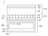
- 1 shows an epitaxial substrate on which a GaN epitaxial film is formed, the epitaxial film being obtained by a method for manufacturing a GaN epitaxial film according to an embodiment of the present invention.
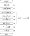
- An example of a method for manufacturing a GaN epitaxial film and a method for manufacturing a semiconductor device using the manufactured epitaxial film will be described.
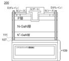
- 1 shows a device using the GaN epitaxial film of the present invention.
- 1 shows a device using the GaN epitaxial film of the present invention.
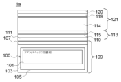
- 1 shows the epitaxial film of Example 1.
- the manufacturing procedure of the epitaxial film and the semiconductor device of Example 2 will be described.
- the manufacturing procedure of the epitaxial film and the semiconductor device of Example 2 will be described.
- Example 3 shows a cross-sectional photograph of the epitaxial film of Example 3.
- the manufacturing procedure of the epitaxial film and the semiconductor device of Example 4 will be described.
- the manufacturing procedure of the epitaxial film and the semiconductor device of Example 5 will be described.
- the manufacturing procedure of the epitaxial film and the semiconductor device of Example 6 will be described.
- the manufacturing procedure of the epitaxial film and the semiconductor device of Comparative Example 1 will be described.
- a GaN epitaxial film manufacturing method comprising the steps of: preparing a support substrate having a diameter of 150 mm or more and a thickness of less than 1 mm, the support substrate having a core made of nitride ceramic sealed with a sealing layer; a substrate manufacturing step of sequentially laminating a planarizing layer and a seed crystal layer made of a SiC single crystal on the support substrate to obtain an epitaxial growth substrate; and an epitaxial step of growing a GaN epitaxial film having a thickness of 7 ⁇ m or more on the epitaxial growth substrate, thereby manufacturing the GaN epitaxial film having a dislocation density of 1.0 ⁇ 10 6 /cm 2 or less, thereby making it possible to produce a GaN thick film having a large diameter but no warping or cracks and a dislocation density of 1.0 ⁇ 10 6 /cm 2 by a simple process at low cost, and have completed the present
- a high-quality semiconductor device can be manufactured at low cost by a semiconductor device manufacturing method characterized in that a device is fabricated on the GaN epitaxial film manufactured by the above-described GaN epitaxial film manufacturing method, and then the planarization layer is etched to separate the device from the support substrate, thereby completing the present invention.
- the GaN epitaxial film obtained by the GaN epitaxial film manufacturing method according to an embodiment of the present invention will be described with reference to FIG. 1.
- a film for a vertical power device MOS-FET
- MOS-FET vertical power device
- the GaN epitaxial film 112 is formed on an epitaxial growth substrate 109.
- the epitaxial growth substrate 109 serves as a base on which the GaN epitaxial film 112 grows, and also serves as a support member for preventing deformation of the GaN epitaxial film 112, such as warping.
- the GaN epitaxial film 112 formed on the epitaxial growth substrate 109 as shown in FIG. 1 will be referred to as an epitaxial substrate 1.
- the epitaxial growth substrate 109 includes a support substrate 100, a planarization layer 105, and a seed crystal layer 107.
- a buffer layer 111 is formed on the epitaxial growth substrate 109, and an ELO layer 113 is further formed on the buffer layer 111.
- the support substrate 100 is a support member for preventing deformation of the GaN epitaxial film 112 , and includes a core 101 and a sealing layer 103 .
- the core 101 is a layer that forms the base of the support substrate 100, and is made of, for example, nitride ceramics such as AlN.
- the sealing layer 103 is a layer that covers the periphery (both sides) of the core 101 to prevent the diffusion of impurities, and is, for example, SiO2 , SiN, or a mixed composition of these, with SiN being preferred.
- the thickness of the coating is, for example, about 200 nm.
- the planarizing layer 105 is a layer that planarizes unevenness resulting from the outer shapes of the core 101 and the sealing layer 103.
- the planarizing layer 105 is also a portion that is removed by etching when the GaN epitaxial film 112 is separated from the epitaxial growth substrate 109 after a device is formed on the GaN epitaxial film 112.
- the planarizing layer 105 contains, for example, any one of silicon oxide, silicon oxynitride, and aluminum arsenide, and more specifically, is silicon oxide (SiO 2 ).
- the planarizing layer 105 is provided at least on the side where the seed crystal layer 107 is bonded, but may be provided so as to encompass the entire substrate, or may be provided on both sides of the substrate.
- the seed crystal layer 107 is a layer that serves as a base on which the GaN epitaxial film 112 grows, and is made of a SiC single crystal.
- SiC is a material that has a lattice constant closer to that of GaN than Si, and is available at a low cost and with a large diameter compared to GaN and AlN, which are crystal layers that can be used to manufacture high-quality GaN epitaxial films. Therefore, a GaN epitaxial film that is free from warping and cracks and has a dislocation density of 1.0 ⁇ 10 6 /cm 2 or less can be formed using a simple process.
- the lower limit of the dislocation density is not particularly limited, but can be set to, for example, 1.0 ⁇ 10 4 /cm 2 or more.
- the crystal structure of the SiC single crystal is not particularly limited, and examples include 6H-SiC, 4H-SiC, and 3C-SiC.
- 4H-SiC is suitable for use in electronic devices
- 6H-SiC and 4H-SiC are suitable for use in visible and ultraviolet light devices.
- the buffer layer 111 is a layer that is provided as necessary when it is necessary to alleviate mismatch caused by the difference in lattice constant between the seed crystal layer 107 and the GaN epitaxial film 112, or to alleviate stress on the GaN epitaxial film 112.
- AlN or AlGaN is used for the buffer layer 111.
- the ELO layer 113 is a layer for reducing dislocation density when the GaN epitaxial film 112 is epitaxially grown, and is formed as necessary when it is desired to further reduce the dislocation density.
- the ELO layer 113 comprises a SiN layer 110 and a GaN layer 115 .
- the SiN layer 110 is an island-like layer that serves as a mask when the GaN layer 115 grows.
- the GaN layer 115 is a layer of GaN that grows from gaps that are not masked by the SiN layer 110, and the GaN layer 115 is a layer that bends the direction of dislocations by restricting the growth direction by the SiN layer 110 during growth, thereby reducing dislocations that reach the GaN epitaxial film 112.
- the density and size of the island-like SiN layer 110 can be appropriately adjusted depending on the device application. Although the characteristics of the SiN layer 110 are conceptually and typically illustrated in FIG. 1, the SiN layer 110 is shown in a layered shape in the following figures for convenience.
- the GaN epitaxial film 112 is a single crystal layer on which a semiconductor device is formed.
- the composition of the GaN epitaxial film 112 is not limited to GaN, but includes other group III nitrides such as InN and AlN and their mixed crystals.
- the composition, structure, and conductivity type of the GaN epitaxial film 112 may be appropriately selected according to the device to be formed, and the GaN epitaxial film 112 may be multi-layered.
- FIG. 1 illustrates a stacked structure of an n-GaN layer 118, a p-GaN layer 122, and a GaN layer 123.
- the thickness of the GaN epitaxial film needs to be 7 ⁇ m or more.
- the upper limit of the thickness of the GaN epitaxial film is not particularly limited, but may be, for example, 50 ⁇ m or less. The above is the description of the GaN epitaxial film 112.
- the diameter of the support substrate needs to be 150 mm or more. If the diameter is less than 150 mm, the diameter of the GaN epitaxial film 112 will also be less than 150 mm, making it impossible to increase the diameter.
- the upper limit of the diameter of the support substrate is not particularly limited, but can be, for example, 500 mm or less.
- the thickness of the support substrate must be less than 1 mm. If the thickness is 1 mm or more, the epitaxial substrate 1 will be 1 mm or more thick, and even if an attempt is made to introduce it into a conventional silicon CMOS line to form a device on the GaN epitaxial film 112, it will be too thick to pass through the line.
- the lower limit of the thickness of the support substrate is not particularly limited, but can be, for example, 0.1 mm or more.
- the thickness of the support substrate 100 should be within the JEITA or SEMI Si substrate thickness standards. This will ensure that conventional silicon CMOS lines can be passed through reliably.
- a planarization layer 105 and a seed crystal layer 107 made of a SiC single crystal are laminated in this order on the support substrate 100 shown in FIG. 1 to obtain a substrate 109 for epitaxial growth (S2 in FIG. 2: substrate manufacturing process).
- a specific method for forming the planarization layer 105 is to form an oxide film such as SiO2 on the surface of the support substrate 100 by plasma CVD, LPCVD, low pressure MOCVD, or the like, perform a thermal stabilization process, and then polish and smooth the surface by a known polishing method such as CMP.
- the thickness of the planarization layer 105 after polishing is, for example, 0.05 ⁇ m or more and 3.0 ⁇ m or less.
- One example of a method for forming the seed crystal layer 107 is to transfer the surface layer of a SiC single crystal substrate. Specifically, hydrogen ions are first implanted into the C-face side of a SiC single crystal substrate fabricated by sublimation to form a split interface in advance. Next, the C-face side of the SiC single crystal substrate into which hydrogen ions have been implanted is bonded to the planarization layer 105. At this time, surface activation treatment can be performed as necessary to eliminate voids.
- a split heat treatment is performed on the SiC single crystal substrate while it is bonded to the planarization layer 105, causing peeling starting from the hydrogen ion implantation layer, transferring the surface layer of the SiC single crystal substrate to the planarization layer 105, and the split interface appears as the surface.
- the damaged layer caused by the peeling is then removed by surface polishing such as CMP, wet etching, or dry etching.
- SiC single crystal with an off-angle of 0° to 4° for the seed crystal layer 107. This allows the III-nitride epitaxial film formed on the seed crystal layer 107 to grow in step-flow mode. If a lower off-angle is required depending on the circumstances, a 0° off substrate may be cut out from a 4° off substrate and used.
- the thickness of the seed crystal layer 107 is, for example, 0.04 ⁇ m or more and 1.0 ⁇ m or less, but is set appropriately depending on the structure and type of device to be formed on the GaN epitaxial film 112.
- the conductivity of the seed crystal layer 107 can be selected to be conductive or non-conductive depending on the structure and type of the device to be formed on the GaN epitaxial film 112. For example, low resistivity (about 20 m ⁇ cm) or high resistivity (1.0 ⁇ 10 ⁇ cm or more) can be used.
- the electrodes can be formed on either the same surface as shown in Figure 3, or on the top and bottom surfaces as shown in Figure 4.
- the device layer portion is the collective name for the portion above the seed crystal layer 107, and refers to the GaN epitaxial film 112, or the combined portion of the buffer layer 111, ELO layer 113, and GaN epitaxial film 112.
- the seed crystal layer 107 is conductive, and the device is used with the epitaxial growth substrate 109 attached.
- the seed crystal layer 107 is used to form a drain electrode, so the seed crystal layer 107 is preferably thick to reduce lateral resistance, and a thickness of 300 nm or more is preferable.
- the resistivity of the seed crystal layer 107 is preferably reduced to about 0.01 to 0.03 ⁇ cm.
- the device 201 shown in Fig. 4 is a case where the seed crystal layer 107 has high resistivity, semi-insulation, or insulation, and after forming a device on the GaN epitaxial film 112, only the device layer portion is separated and used as a device.
- the seed crystal layer 107 is preferably thin since it is to be removed, and is preferably less than 300 nm, for example. Note that when the seed crystal layer 107 is conductive, there is no need to remove the seed crystal layer 107, and therefore the device can be used in the electrode formation type of Fig. 4 with the seed crystal layer 107 remaining under the device layer portion. For devices where it is not desired to pass current underneath, such as RF devices, a semi-insulating seed layer 107 is desirable.
- the buffer layer 111 is formed, for example, by MOCVD.
- the ELO layer 113 is formed as necessary. Specifically, a step of forming island-shaped SiN layers 110 (S4 in FIG. 2) and an ELO step of growing GaN layer 115 using SiN layer 110 as a mask (S5 in FIG. 2) are performed. This makes it possible to further reduce the dislocation density in the GaN epitaxial film.
- the formation step and the ELO step may be alternately performed as necessary to form multiple SiN layers 110 and GaN layers 115. This can further reduce the dislocation density of the GaN epitaxial film 112 compared to performing the formation step and the ELO step once each.
- a GaN epitaxial film 112 is grown (S6 in FIG. 2: growth step).
- the GaN epitaxial film 112 is formed on the outermost SiN layer 110 or GaN layer 115 when the formation step and ELO step have been performed, and is formed on the buffer layer 111 when the formation step and ELO step have not been performed and the buffer layer 111 has been formed.
- the GaN epitaxial film 112 is formed on the seed crystal layer 107.
- the surface of the seed crystal layer 107 on which the epitaxial growth is performed is preferably a Si surface, which tends to make the epitaxial layer flat, but may be a C surface.
- Steps S3 to S6 are collectively referred to as the epitaxial process. The above is a description of the method for producing the GaN epitaxial film 112.
- the desired device is fabricated on the GaN epitaxial film 112 (S7 in FIG. 2). Fabrication of the device includes changing the conductivity type by ion implantation, etc., and forming insulating layers and electrodes by sputtering, etc.
- the device is completed through the above steps.
- the support substrate 100 is to be separated from the GaN epitaxial film 112 even after a device is formed on the GaN epitaxial film 112, as in the case of device 201 shown in Fig. 4, the device is separated from the support substrate 100 by etching the planarizing layer 105 (S8 in Fig. 2).
- the planarizing layer 105 There are no particular limitations on the etchant as long as it dissolves the planarizing layer 105, but when the planarizing layer 105 is made of SiO2 , an HF (hydrogen fluoride) solution can be used as an example.
- the semiconductor device to be manufactured is not particularly limited, but examples thereof include LEDs, LDs (laser diodes), PDs (photodiodes), HEMTs (high mobility field effect transistors), FETs, and HBTs.
- Example 1 Epitaxial substrate for vertical device First, a GaN epitaxial film 112 was grown in the following manner to produce an epitaxial substrate 1a shown in FIG.
- a nitride ceramic substrate (AlN) serving as a core 101 was wrapped in a sealing layer 103, and a planarizing layer 105 of silicon oxide with a thickness of 0.05 ⁇ m to 3.0 ⁇ m was provided on at least the side where the seed crystal layer 107 was to be bonded.
- AlN nitride ceramic substrate
- 4H-SiC resistivity 20 ⁇ cm, thickness 0.04 ⁇ m to 1.0 ⁇ m, epitaxial growth surface is a Si surface with an off angle of 0°
- the epitaxial growth substrate 109 was placed in a growth apparatus and heated to a growth temperature (1000 to 1200° C.), and TMA (trimethylaluminum), TMG (trimethylgallium), and NH 3 gas were supplied to form an Al 0.2 Ga 0.8 N layer of 0.15 ⁇ m as a buffer layer 111 on the seed crystal layer 107.
- the Al 0.2 Ga 0.8 N layer was doped with Si as an n-type dopant at 1.0 ⁇ 10 19 atoms/cm 3 .
- the supply of TMA and TMG was interrupted, and SiH 4 and NH 3 were supplied to grow the SiN layer 110 on the buffer layer 111 in an island shape with a thickness of 1 nm, after which the supply of SiH 4 was stopped and TMG was flowed to epitaxially grow the GaN layer 115 to a thickness of 3.0 ⁇ m.
- the Si-doped n-GaN layer 114 was epitaxially grown to a thickness of 7 ⁇ m, and further, the Mg-doped p-GaN layer 119 was formed to a thickness of 0.5 ⁇ m, and the GaN layer 120 was formed to a thickness of 0.5 ⁇ m thereon.
- Mg doped in the GaN layer is often inactivated immediately after epitaxial growth, and in that case, a separate heat treatment is required to activate it as a p-type dopant.
- heat treatment was performed at 1300° C. in a nitrogen atmosphere at normal pressure.
- Mg-doped p-GaN layer is described, it should be understood that the same treatment was performed.
- the dislocation density near the surface of the epitaxial substrate 1a was evaluated in a range of 20 ⁇ m ⁇ 20 ⁇ m using a Hitachi SU-70 semiconductor backscattered electron detector (PDBSE) at an accelerating voltage of 5 kV.
- the dislocation density was 7.5 ⁇ 10 5 cm ⁇ 2 , and an epitaxial substrate 1a for a vertical device on which a high-quality GaN epitaxial film was grown could be manufactured.
- the dislocation density rapidly decreases in the upper layer. Therefore, if the epitaxial substrate is one on which a GaN epitaxial film of 7 ⁇ m or more is grown according to the present invention, the quality required for device performance can be guaranteed by evaluating the surface vicinity of the epitaxial substrate produced.
- Example 2 MOS-FET First, a GaN epitaxial film 112 was grown in the following manner to produce an epitaxial substrate 1b shown in FIG. 6(a).
- a nitride ceramic substrate (AlN) serving as a core 101 was wrapped in a sealing layer 103, and a planarization layer 105 of silicon oxide with a thickness of 0.05 ⁇ m to 3.0 ⁇ m was provided on at least the side where the seed crystal layer 107 was to be bonded.
- 4H—SiC resistivity 20 ⁇ cm, thickness 0.04 ⁇ m to 1.0 ⁇ m, epitaxial growth surface is a Si surface with an off angle of 0°
- 4H—SiC resistivity 20 ⁇ cm, thickness 0.04 ⁇ m to 1.0 ⁇ m, epitaxial growth surface is a Si surface with an off angle of 0°
- an Al 0.2 Ga 0.8 N layer of 0.15 ⁇ m was formed as the buffer layer 111 on the seed crystal layer 107 in the same manner as in Example 1.
- the Al 0.2 Ga 0.8 N layer was doped with Si at 1.0 ⁇ 10 19 atoms/cm 3 .
- a SiN layer 110 was grown in an island shape with a thickness of 1 nm on the buffer layer 111, and then a GaN layer 115 was epitaxially grown to a thickness of 2.0 ⁇ m.
- a SiN layer 110 was grown in an island shape with a thickness of 1 nm on top of that, and then a GaN layer 115 was epitaxially grown to a thickness of 1.0 ⁇ m.
- the number of times the ELO layer 113 is laminated is increased compared to the first embodiment.
- a Si-doped n-GaN layer 114 was epitaxially grown to a thickness of 7 ⁇ m, a Mg-doped p-GaN layer 119 was grown to a thickness of 0.5 ⁇ m, and a GaN layer 120 was grown on top of that to a thickness of 0.5 ⁇ m.
- the epitaxial substrate 1b was manufactured.
- the dislocation density near the surface of the epitaxial substrate 1b was measured in the same manner as in Example 1 and was found to be 6.0 ⁇ 10 5 cm ⁇ 2 , indicating that an epitaxial substrate 1b for vertical devices having a high-quality GaN epitaxial film grown thereon could be manufactured.
- this epitaxial substrate 1b for a vertical device was processed by the following device process to fabricate a vertical power device (MOS-FET).
- MOS-FET vertical power device
- a mask 301 with a predetermined pattern shape was formed on the outermost surface by photolithography, and an n + layer 303 was formed on the outermost GaN layer 120 by ion implantation into the opening of the mask 301.
- a mask 301 having an opening formed in the center of the n + layer 303 was formed by photolithography, and dry etching was performed down to the n-GaN layer 114 .
- a mask 301 was formed on the dry-etched portion by photolithography, and a SiN film 305 was formed by sputtering. Thereafter, the mask 301 was removed, and a SiO2 film 307 was formed by sputtering, as shown in Fig. 6(e).
- a mask 301 was formed by photolithography, and then the center of the SiO2 film 307 was etched by dry etching. Thereafter, the mask 301 was removed, and a mask 301 for the gate electrode was formed by photolithography, as shown in Fig. 7(a).
- a gate electrode 309 was sputtered, and the mask 301 was removed.
- a mask 301 was formed by photolithography, and a SiO2 film 311 was formed by sputtering to insulate the gate electrode 309.
- a source electrode 313 was sputtered.
- a mask 301 for element isolation was formed by photolithography, and then dry etching was performed down to the SiO2 layer, which is the planarization layer 105.
- the layers above the seed crystal layer 107 are collectively shown as a device layer portion 315 for the sake of simplicity.
- the mask 301 was removed, and a temporary support substrate 317 was attached to the device layer portion 315, and immersed in an HF solution 319. This dissolved the SiO 2 layer, which was the planarization layer 105, and separated the device layer portion 315 from the portion below the planarization layer 105.
- a drain electrode 316 was sputtered onto the seed crystal layer 107 on the side of the separated device layer 315, and an ohmic electrode was formed by RTA (Rapid Thermal Anneal) in a nitrogen atmosphere, and then Au 320 was sputtered onto the surface.
- RTA Rapid Thermal Anneal
- Au 320 was sputtered onto the surface.
- a metal bond was formed with a substrate on which Au 320 was sputtered onto the surface of a conductive substrate 321 prepared in advance.
- each chip on the side of the separated device layer 315 was picked up and soldered onto a substrate 323 on which an electronic circuit was formed. This allowed the formation of a vertical power device (MOS-FET) as a semiconductor device.
- MOS-FET vertical power device
- Example 3 SBD (Schottky Barrier Diode) First, an HVPE-GaN epitaxial film 401 was grown as the GaN epitaxial film 112 in the following manner to produce the epitaxial substrate 1c shown in FIG. 8(a).
- a nitride ceramic substrate (AlN) serving as a core 101 was wrapped in a sealing layer 103, and a planarization layer 105 of silicon oxide with a thickness of 0.05 ⁇ m to 3.0 ⁇ m was provided on at least the side where the seed crystal layer 107 was to be bonded.
- 4H—SiC resistivity 20 ⁇ cm, thickness 0.04 ⁇ m to 1.0 ⁇ m, epitaxial growth surface is a Si surface with an off angle of 0°
- 4H—SiC resistivity 20 ⁇ cm, thickness 0.04 ⁇ m to 1.0 ⁇ m, epitaxial growth surface is a Si surface with an off angle of 0°
- an Al 0.2 Ga 0.8 N layer of 0.15 ⁇ m was formed as the buffer layer 111 on the seed crystal layer 107 in the same manner as in Example 1.
- the Al 0.2 Ga 0.8 N layer was doped with Si at 1.0 ⁇ 10 19 atoms/cm 3 .
- a SiN layer 110 was grown on the buffer layer 111 in an island shape with a thickness of 1 nm, and then a GaN layer 115 was epitaxially grown to a thickness of 3.4 ⁇ m. Then, a SiN layer 110 was grown in an island shape with a thickness of 1 nm, and then a GaN layer 115 was epitaxially grown to a thickness of 2.1 ⁇ m.
- HVPE-GaN epitaxial film 401 was further epitaxially grown to a thickness of 19 ⁇ m using HVPE (Hydride Vapor Phase Epitaxy). Through the above steps, the epitaxial substrate 1c was manufactured.
- the dislocation density near the surface of HVPE-GaN epitaxial film 401 was measured in the same manner as in Example 1 and was found to be 3.0 ⁇ 10 5 cm ⁇ 2 , indicating that an epitaxial substrate 1 c for vertical devices having a high quality GaN epitaxial film grown thereon could be produced.
- a layer with a thickness of approximately 24.7 ⁇ m was observed in the SEM image shown in FIG. 9(a). This is approximately the same as the total thickness of the buffer layer 111 (thickness 0.15 ⁇ m), GaN layer 115 (thickness 3.4 ⁇ m + 2.1 ⁇ m), and HVPE-GaN epitaxial film 401 (19 ⁇ m), and it was found that the total thickness of these layers was as targeted.
- the TEM images shown in FIGS. 9(d) and 9(e) confirm that the planarizing layer 105 (SiO 2 ), the seed crystal layer 107 (SiC), the buffer layer 111 (Al 0.2 Ga 0.8 N), and the SiN layer 110 are laminated in this order.
- this epitaxial substrate 1c for a vertical device was processed by the following device process to fabricate a vertical power device (SBD).
- SBD vertical power device
- a mask 501 for a Schottky electrode was prepared by photolithography, and a Schottky electrode 503 was formed by sputtering.
- a mask 501 was formed by photolithography, and then dry etching was performed down to the SiO2 planarization layer 105.
- a temporary support substrate 504 was bonded to the Schottky electrode 503 side, and immersed in an HF solution 319 to dissolve the SiO2 planarization layer 105, separating the upper part (device layer portion) and the lower part from the planarization layer 105, and exposing the SiC seed crystal layer 107 on the device layer portion side.
- a drain electrode 505 was formed on the surface of the seed crystal layer 107, and then Au 507 was formed as shown in FIG. 8(f). Furthermore, a metal bond was performed with a conductive substrate 321 prepared in advance to which Au 507 was attached. Furthermore, as shown in FIG. 8(g), each of the separated chips was picked up and soldered onto a substrate 322 on which an electronic circuit was formed. This allowed the formation of a vertical power device (SBD) as a semiconductor device.
- SBD vertical power device
- Example 4 Vertical Light Emitting Device First, a GaN epitaxial film 112 was grown in the following manner to produce an epitaxial substrate 1d shown in FIG. 10(a).
- a nitride ceramic substrate (AlN) serving as a core 101 was wrapped in a sealing layer 103, and a planarization layer 105 of silicon oxide with a thickness of 0.05 ⁇ m to 3.0 ⁇ m was provided on at least the side where the seed crystal layer 107 was to be bonded.
- 6H-SiC resistivity 20 ⁇ cm, thickness 0.04 ⁇ m to 1.0 ⁇ m, epitaxial growth surface is a Si surface with an off angle of 0°
- 6H-SiC resistivity 20 ⁇ cm, thickness 0.04 ⁇ m to 1.0 ⁇ m, epitaxial growth surface is a Si surface with an off angle of 0°
- an Al 0.2 Ga 0.8 N layer was formed to a thickness of 0.15 ⁇ m as the buffer layer 111 on the seed crystal layer 107 in the same manner as in Example 1.
- the Al 0.2 Ga 0.8 N layer was doped with Si at 1.0 ⁇ 10 19 atoms/cm 3 .
- a SiN layer 110 was grown in an island shape with a thickness of 1 nm on the buffer layer 111, and then a GaN layer 115 was epitaxially grown with a thickness of 3.0 ⁇ m.
- a SiN layer 110 was grown on top of that in an island shape with a thickness of 1 nm, and then a GaN epitaxial film 112 was epitaxially grown with a thickness of 4.0 ⁇ m.
- the dislocation density near the surface of the epitaxial substrate 1d was measured in the same manner as in Example 1 and was found to be 9.0 ⁇ 10 5 cm ⁇ 2 , indicating that an epitaxial substrate 1d for vertical devices having a high-quality GaN epitaxial film 112 grown thereon could be manufactured.
- this epitaxial substrate 1d for a vertical device was processed by the following device process to fabricate a vertical light emitting device.
- a mask 601 was formed by photolithography on the outermost surface of an epitaxial substrate 1c for a vertical device, and then a p-electrode 603 was formed by sputtering.
- a mask 601 was formed by photolithography to protect the p-electrode 603 and also to separate elements.
- etching was performed down to the SiO2 planarization layer 105.
- a temporary support substrate 605 was attached to the p-electrode 603 side and immersed in an HF solution 319 to dissolve the planarization layer 105, and the device layer portion was separated from the part below the planarization layer 105.
- an n-electrode 607 was formed by sputtering on the seed crystal layer 107 exposed on the separated device layer side. Furthermore, as shown in FIG. 10(g), Au was sputtered onto the surface, and a metal bond was formed with a conductive substrate 321 prepared in advance, on whose surface Au was formed, and a sintering process was performed. Furthermore, as shown in FIG. 10(f), each chip was picked up and soldered onto a substrate 322 on which an electronic circuit was formed. This allowed the formation of a vertical light-emitting element as a semiconductor device.
- Example 5 Lateral power device First, a GaN epitaxial film 112 was grown in the following manner to produce an epitaxial substrate 1e for a lateral power device as shown in FIG. 11(a).
- a nitride ceramic substrate (AlN) serving as a core 101 was wrapped in a sealing layer 103, and a planarization layer 105 of silicon oxide with a thickness of 0.05 ⁇ m to 3.0 ⁇ m was provided on at least the side where the seed crystal layer 107 was to be bonded.
- a SiN layer 110 was grown in an island shape with a thickness of 1 nm on the buffer layer 111, then a GaN layer 115 was epitaxially grown to a thickness of 3.4 ⁇ m, a SiN layer 110 was grown in an island shape with a thickness of 1 nm on top of that, and further a GaN epitaxial film 112 was epitaxially grown to a thickness of 4.0 ⁇ m.
- An Al 0.25 Ga 0.75 N layer 701 serving as a barrier layer was epitaxially grown thereon to a thickness of 25 nm, and an Mg-doped p-GaN layer 703 was further grown thereon to a thickness of 3 nm.
- an epitaxial substrate 1e for a lateral power device was manufactured.
- the dislocation density near the surface of the epitaxial substrate 1e was measured in the same manner as in Example 1 and was found to be 9.0 ⁇ 10 5 cm ⁇ 2 , indicating that an epitaxial substrate 1e for use in a lateral power device having a high-quality GaN epitaxial film 112 grown thereon could be manufactured.
- this epitaxial substrate 1e for a lateral power device was processed by the following device process to fabricate a lateral power device.
- a mask 705 for forming S (source) and D (drain) electrodes was formed by photolithography, and then 4 nm was etched away to the top of the Al 0.25 GaN layer 701 by dry etching.
- an S electrode 707 and a D electrode 709 were formed by sputtering. Furthermore, as shown in FIG. 11(c), a mask 705 for forming a G (gate) electrode was formed by photolithography, and a G electrode 711 was sputtered and sintered.
- a mask 705 for isolating elements was formed by photolithography, and etching was performed by dry etching down to the planarization layer 105 as shown in Fig. 11(d). Furthermore, as shown in Fig. 11(e), a temporary support substrate 713 was bonded, and immersed in an HF solution 319 to dissolve the SiO2 of the planarization layer 105, and the device layer portion was separated from the lower part of the planarization layer 105.
- the exposed seed crystal layer 107 was covered with a thin film of Au 715 and metal-bonded to a heat dissipation substrate 717 covered with a thin film of Au 715.
- each chip was picked up and mounted at a designated position on the substrate 322 on which the electronic circuit was formed. This resulted in the formation of a lateral power device as a semiconductor device.
- Example 6 Lateral Light Emitting Element First, a GaN epitaxial film 112 was grown in the following manner to produce an epitaxial substrate 1f for a lateral light emitting element as shown in FIG. 12(a).
- a nitride ceramic substrate (AlN) serving as a core 101 was wrapped in a sealing layer 103, and a planarization layer 105 of silicon oxide with a thickness of 0.05 ⁇ m to 3.0 ⁇ m was provided on at least the side where the seed crystal layer 107 was to be bonded.
- 6H-SiC resistivity 20 ⁇ cm, thickness 0.04 ⁇ m to 1.0 ⁇ m, epitaxial growth surface is a Si surface with an off angle of 0°
- 6H-SiC resistivity 20 ⁇ cm, thickness 0.04 ⁇ m to 1.0 ⁇ m, epitaxial growth surface is a Si surface with an off angle of 0°
- an Al 0.2 Ga 0.8 N layer was formed to a thickness of 0.15 ⁇ m as a buffer layer 111 on the seed crystal layer 107 in the same manner as in Example 1.
- the Al 0.2 Ga 0.8 N layer was doped with Si at 1.0 ⁇ 10 19 atoms/cm 3 .
- a SiN layer 110 was grown in an island shape with a thickness of 1 nm on the buffer layer 111, then a GaN layer 115 was epitaxially grown with a thickness of 3 ⁇ m, and a SiN layer 110 was grown on top of that in an island shape with a thickness of 1 nm, and then a GaN epitaxial film 112 was epitaxially grown with a thickness of 4 ⁇ m.
- the dislocation density near the surface of the epitaxial substrate 1f was measured in the same manner as in Example 1 and was found to be 9.0 ⁇ 10 5 cm ⁇ 2 , indicating that an epitaxial substrate 1f for a lateral light emitting device having a high quality GaN epitaxial film 112 grown thereon could be manufactured.
- this epitaxial substrate 1f for the lateral light emitting device was processed by the following device process to fabricate a lateral light emitting device.
- a mask 901 was formed by photolithography, and a p-electrode 903 was formed by sputtering.
- a mask 901 is formed by photolithography to form an n-electrode, and the n-electrode forming portion and element isolation portion are simultaneously dry-etched down to the top of the Al 0.2 Ga 0.8 N buffer layer 111 by dry etching.
- a mask 901 was formed by photolithography to form an n-electrode 904, and sintering was performed to form an ohmic electrode.
- a mask 901 was formed by photolithography for element isolation, and the buffer layer 111 ( Al0.2Ga0.8N ) and the seed crystal layer 107 ( SiC) were dry etched to expose the SiO2 planarization layer 105.
- a temporary support substrate 906 was bonded, and the substrate was immersed in an HF solution 319 to dissolve the SiO 2 planarization layer 105.
- the device layer portion was separated from the lower portion of the planarization layer 105, and a thin film 905 of Au was formed on the seed crystal layer 107 exposed on the device layer portion side ( FIG. 12( f )).
- each chip was picked up and mounted at a designated position on the substrate 322 on which the electronic circuit was formed. This resulted in the formation of a horizontal light-emitting element as a semiconductor device.
- Example 7 Epitaxial Substrate for Vertical Device An epitaxial substrate was produced in the same manner as in Example 1, except that the SiN layer 110 and the GaN layer 115 thereon were not formed.
- the dislocation density of the GaN layer 120 was measured in the same manner as in Example 1 and found to be 1 ⁇ 10 6 cm ⁇ 2 , which was higher than that of Example 1, but was a high-quality epitaxial substrate with a dislocation density of 1 ⁇ 10 6 cm ⁇ 2 or less.
- a nitride ceramic substrate (AlN) serving as a core 101 was wrapped in a sealing layer 103, and a planarization layer 105 of silicon oxide with a thickness of 0.05 ⁇ m to 3.0 ⁇ m was provided on at least the side where the seed crystal layer 107 was to be bonded.
- Si resistivity 20 ⁇ cm, thickness 0.04 ⁇ m to 1.0 ⁇ m, off angle 0°
- SiC resistivity 20 ⁇ cm, thickness 0.04 ⁇ m to 1.0 ⁇ m, off angle 0°
- SiC resistivity 20 ⁇ cm, thickness 0.04 ⁇ m to 1.0 ⁇ m, off angle 0°
- an Al 0.2 Ga 0.8 N layer was formed to a thickness of 0.15 ⁇ m as the buffer layer 111 on the seed crystal layer 107 in the same manner as in Example 1.
- the Al 0.2 Ga 0.8 N layer was doped with Si to 1.0 ⁇ 10 19 atoms/cm 3.
- a GaN layer 907 was epitaxially grown to a thickness of 7 ⁇ m in the same manner as in Example 1.
- the dislocation density near the surface of the GaN layer 907 was measured in the same manner as in Example 1, and was found to be 2 ⁇ 10 8 cm -2 , which was higher than that of the Example. Thereafter, the GaN layer 909 was further epitaxially grown to a thickness of 19 ⁇ m by HVPE, to produce an epitaxial substrate for a vertical device. The dislocation density near the surface of the GaN layer 907 was further measured in the same manner as in Example 1, and was found to be 9 ⁇ 10 6 cm -2 , which was higher than that of the Example.
- a method for producing a GaN epitaxial film comprising the steps of: A preparation step of preparing a support substrate having a diameter of 150 mm or more and a thickness of less than 1 mm, the support substrate having a nitride ceramic core sealed with a sealing layer; a substrate manufacturing process for obtaining an epitaxial growth substrate by sequentially stacking a planarizing layer and a seed crystal layer made of a SiC single crystal on the support substrate; an epitaxial step of growing a GaN epitaxial film having a thickness of 7 ⁇ m or more on the epitaxial growth substrate; and producing the GaN epitaxial film having a dislocation density of 1.0 ⁇ 10 6 /cm 2 or less by containing the above.
- [4] A method for producing a GaN epitaxial film according to any one of [1] to [3] above, characterized in that the SiC single crystal has an off-angle of 0° to 4°.
- [5] A method for manufacturing a semiconductor device, comprising the steps of: forming a device on the GaN epitaxial film manufactured by the GaN epitaxial film manufacturing method according to any one of [1] to [4] above; and then etching the planarization layer to separate the device from the support substrate.
- the present invention is not limited to the above-described embodiments.
- the above-described embodiments are merely examples, and anything that has substantially the same configuration as the technical idea described in the claims of the present invention and exhibits similar effects is included within the technical scope of the present invention.
Landscapes
- Chemical & Material Sciences (AREA)
- Engineering & Computer Science (AREA)
- Crystallography & Structural Chemistry (AREA)
- Materials Engineering (AREA)
- Metallurgy (AREA)
- Organic Chemistry (AREA)
- Chemical Kinetics & Catalysis (AREA)
- General Chemical & Material Sciences (AREA)
- Inorganic Chemistry (AREA)
- Recrystallisation Techniques (AREA)
- Crystals, And After-Treatments Of Crystals (AREA)
Priority Applications (3)
| Application Number | Priority Date | Filing Date | Title |
|---|---|---|---|
| KR1020257043103A KR20260029292A (ko) | 2023-07-03 | 2024-06-18 | GaN 에피택셜 막의 제조방법 및 반도체 디바이스의 제조방법 |
| CN202480042967.8A CN121399308A (zh) | 2023-07-03 | 2024-06-18 | GaN外延膜的制造方法及半导体器件的制造方法 |
| EP24835888.9A EP4741542A1 (en) | 2023-07-03 | 2024-06-18 | Production method for gan epitaxial film and production method for semiconductor device |
Applications Claiming Priority (2)
| Application Number | Priority Date | Filing Date | Title |
|---|---|---|---|
| JP2023-109212 | 2023-07-03 | ||
| JP2023109212A JP2025007662A (ja) | 2023-07-03 | 2023-07-03 | GaNエピタキシャル膜の製造方法及び半導体デバイスの製造方法 |
Publications (1)
| Publication Number | Publication Date |
|---|---|
| WO2025009374A1 true WO2025009374A1 (ja) | 2025-01-09 |
Family
ID=94172055
Family Applications (1)
| Application Number | Title | Priority Date | Filing Date |
|---|---|---|---|
| PCT/JP2024/021963 Ceased WO2025009374A1 (ja) | 2023-07-03 | 2024-06-18 | GaNエピタキシャル膜の製造方法及び半導体デバイスの製造方法 |
Country Status (6)
| Country | Link |
|---|---|
| EP (1) | EP4741542A1 (enExample) |
| JP (1) | JP2025007662A (enExample) |
| KR (1) | KR20260029292A (enExample) |
| CN (1) | CN121399308A (enExample) |
| TW (1) | TW202517849A (enExample) |
| WO (1) | WO2025009374A1 (enExample) |
Citations (17)
| Publication number | Priority date | Publication date | Assignee | Title |
|---|---|---|---|---|
| JPH10312971A (ja) * | 1997-03-13 | 1998-11-24 | Nec Corp | III−V族化合物半導体膜とその成長方法、GaN系半導体膜とその形成方法、GaN系半導体積層構造とその形成方法、GaN系半導体素子とその製造方法 |
| JP2013177285A (ja) | 2011-10-07 | 2013-09-09 | Sumitomo Electric Ind Ltd | GaN系膜の製造方法およびそれに用いられる複合基板 |
| JP2015029042A (ja) | 2013-06-27 | 2015-02-12 | 株式会社東芝 | 窒化物半導体素子、窒化物半導体ウェーハ及び窒化物半導体層の形成方法 |
| JP2016041654A (ja) | 2005-12-15 | 2016-03-31 | サン−ゴバン クリストー エ デテクトゥール | 低転位密度GaNの成長のためのプロセス |
| JP2018088528A (ja) | 2013-06-27 | 2018-06-07 | 株式会社東芝 | 窒化物半導体素子、窒化物半導体ウェーハ及び窒化物半導体層の形成方法 |
| JP2019523994A (ja) | 2016-06-14 | 2019-08-29 | クロミス,インコーポレイテッド | 電力およびrf用途用の設計された基板構造 |
| JP2020505767A (ja) | 2017-01-18 | 2020-02-20 | クロミス,インコーポレイテッド | パワーデバイス用の窒化ガリウムエピタキシャル構造 |
| JP2020033211A (ja) | 2018-08-29 | 2020-03-05 | 株式会社サイオクス | 窒化物半導体基板の製造方法、窒化物半導体基板および積層構造体 |
| JP2020033253A (ja) | 2019-09-20 | 2020-03-05 | 株式会社サイオクス | 窒化物半導体基板 |
| JP2020033212A (ja) | 2018-08-29 | 2020-03-05 | 株式会社サイオクス | 窒化物半導体基板、窒化物半導体基板の製造方法および積層構造体 |
| JP2020033254A (ja) | 2019-09-20 | 2020-03-05 | 株式会社サイオクス | 窒化物半導体基板 |
| JP2020033210A (ja) | 2018-08-29 | 2020-03-05 | 株式会社サイオクス | 窒化物半導体基板の製造方法、窒化物半導体基板および積層構造体 |
| JP2020070229A (ja) | 2018-10-26 | 2020-05-07 | 株式会社サイオクス | 窒化物半導体基板の製造方法、窒化物半導体基板および積層構造体 |
| WO2021230148A1 (ja) | 2020-05-11 | 2021-11-18 | 信越化学工業株式会社 | Iii-v族化合物結晶用ベース基板及びその製造方法 |
| WO2022004165A1 (ja) * | 2020-07-01 | 2022-01-06 | 信越化学工業株式会社 | 大口径iii族窒化物系エピタキシャル成長用基板とその製造方法 |
| JP2022056492A (ja) | 2020-09-30 | 2022-04-11 | 信越半導体株式会社 | 紫外線発光素子用エピタキシャルウェーハ、紫外線発光素子用金属貼り合わせ基板の製造方法、紫外線発光素子の製造方法、及び紫外線発光素子アレイの製造方法 |
| WO2023027045A1 (ja) * | 2021-08-25 | 2023-03-02 | 京セラ株式会社 | 半導体素子の製造方法、半導体素子及び半導体装置 |
Family Cites Families (1)
| Publication number | Priority date | Publication date | Assignee | Title |
|---|---|---|---|---|
| US10622468B2 (en) * | 2017-02-21 | 2020-04-14 | QROMIS, Inc. | RF device integrated on an engineered substrate |
-
2023
- 2023-07-03 JP JP2023109212A patent/JP2025007662A/ja active Pending
-
2024
- 2024-06-18 KR KR1020257043103A patent/KR20260029292A/ko active Pending
- 2024-06-18 CN CN202480042967.8A patent/CN121399308A/zh active Pending
- 2024-06-18 EP EP24835888.9A patent/EP4741542A1/en active Pending
- 2024-06-18 WO PCT/JP2024/021963 patent/WO2025009374A1/ja not_active Ceased
- 2024-06-19 TW TW113122617A patent/TW202517849A/zh unknown
Patent Citations (20)
| Publication number | Priority date | Publication date | Assignee | Title |
|---|---|---|---|---|
| JPH10312971A (ja) * | 1997-03-13 | 1998-11-24 | Nec Corp | III−V族化合物半導体膜とその成長方法、GaN系半導体膜とその形成方法、GaN系半導体積層構造とその形成方法、GaN系半導体素子とその製造方法 |
| JP2016041654A (ja) | 2005-12-15 | 2016-03-31 | サン−ゴバン クリストー エ デテクトゥール | 低転位密度GaNの成長のためのプロセス |
| JP2013177285A (ja) | 2011-10-07 | 2013-09-09 | Sumitomo Electric Ind Ltd | GaN系膜の製造方法およびそれに用いられる複合基板 |
| JP2015029042A (ja) | 2013-06-27 | 2015-02-12 | 株式会社東芝 | 窒化物半導体素子、窒化物半導体ウェーハ及び窒化物半導体層の形成方法 |
| JP2018088528A (ja) | 2013-06-27 | 2018-06-07 | 株式会社東芝 | 窒化物半導体素子、窒化物半導体ウェーハ及び窒化物半導体層の形成方法 |
| JP2019523994A (ja) | 2016-06-14 | 2019-08-29 | クロミス,インコーポレイテッド | 電力およびrf用途用の設計された基板構造 |
| JP2020505767A (ja) | 2017-01-18 | 2020-02-20 | クロミス,インコーポレイテッド | パワーデバイス用の窒化ガリウムエピタキシャル構造 |
| JP2022165964A (ja) | 2017-01-18 | 2022-11-01 | クロミス,インコーポレイテッド | パワーデバイス用の窒化ガリウムエピタキシャル構造 |
| JP2020033211A (ja) | 2018-08-29 | 2020-03-05 | 株式会社サイオクス | 窒化物半導体基板の製造方法、窒化物半導体基板および積層構造体 |
| JP2020033212A (ja) | 2018-08-29 | 2020-03-05 | 株式会社サイオクス | 窒化物半導体基板、窒化物半導体基板の製造方法および積層構造体 |
| JP2020033210A (ja) | 2018-08-29 | 2020-03-05 | 株式会社サイオクス | 窒化物半導体基板の製造方法、窒化物半導体基板および積層構造体 |
| JP2020070230A (ja) | 2018-10-26 | 2020-05-07 | 株式会社サイオクス | 窒化物半導体基板 |
| JP2020070229A (ja) | 2018-10-26 | 2020-05-07 | 株式会社サイオクス | 窒化物半導体基板の製造方法、窒化物半導体基板および積層構造体 |
| JP2020033254A (ja) | 2019-09-20 | 2020-03-05 | 株式会社サイオクス | 窒化物半導体基板 |
| JP2020033253A (ja) | 2019-09-20 | 2020-03-05 | 株式会社サイオクス | 窒化物半導体基板 |
| WO2021230148A1 (ja) | 2020-05-11 | 2021-11-18 | 信越化学工業株式会社 | Iii-v族化合物結晶用ベース基板及びその製造方法 |
| WO2022004165A1 (ja) * | 2020-07-01 | 2022-01-06 | 信越化学工業株式会社 | 大口径iii族窒化物系エピタキシャル成長用基板とその製造方法 |
| JP2022012558A (ja) | 2020-07-01 | 2022-01-17 | 信越化学工業株式会社 | 大口径iii族窒化物系エピタキシャル成長用基板とその製造方法 |
| JP2022056492A (ja) | 2020-09-30 | 2022-04-11 | 信越半導体株式会社 | 紫外線発光素子用エピタキシャルウェーハ、紫外線発光素子用金属貼り合わせ基板の製造方法、紫外線発光素子の製造方法、及び紫外線発光素子アレイの製造方法 |
| WO2023027045A1 (ja) * | 2021-08-25 | 2023-03-02 | 京セラ株式会社 | 半導体素子の製造方法、半導体素子及び半導体装置 |
Also Published As
| Publication number | Publication date |
|---|---|
| TW202517849A (zh) | 2025-05-01 |
| KR20260029292A (ko) | 2026-03-04 |
| CN121399308A (zh) | 2026-01-23 |
| EP4741542A1 (en) | 2026-05-13 |
| JP2025007662A (ja) | 2025-01-17 |
Similar Documents
| Publication | Publication Date | Title |
|---|---|---|
| JP5441297B2 (ja) | Iii−v族発光デバイス | |
| US10833186B2 (en) | Gallium nitride epitaxial structures for power devices | |
| CN101528991B (zh) | 蓝宝石衬底、使用该蓝宝石衬底的氮化物半导体发光元件及氮化物半导体发光元件的制造方法 | |
| CN102308370B (zh) | 外延晶片、氮化镓系半导体器件的制作方法、氮化镓系半导体器件及氧化镓晶片 | |
| JP5441298B2 (ja) | Iii−v族発光デバイスを成長させるための基板 | |
| US11335557B2 (en) | Multi-deposition process for high quality gallium nitride device manufacturing | |
| WO2005112080A1 (ja) | Iii族窒化物半導体結晶およびその製造方法、iii族窒化物半導体デバイスおよびその製造方法ならびに発光機器 | |
| CN103828030B (zh) | 半导体元件、hemt元件、以及半导体元件的制造方法 | |
| JPWO2005015642A1 (ja) | 半導体装置及びその製造方法 | |
| JP7052503B2 (ja) | トランジスタの製造方法 | |
| JP4210823B2 (ja) | シヨットキバリアダイオード及びその製造方法 | |
| WO2008012877A1 (fr) | DISPOSITIF À SEMI-CONDUCTEURS COMPOSÉ EMPLOYANT UN SUBSTRAT DE SiC ET PROCÉDÉ POUR PRODUIRE CELUI-CI | |
| JP2016058693A (ja) | 半導体装置、半導体ウェーハ、及び、半導体装置の製造方法 | |
| US20230343890A1 (en) | Epitaxial wafer for ultraviolet light emitting device, method for producing metal bonded substrate for ultraviolet light emitting device, method for producing ultraviolet light emitting device, and method for producing ultraviolet light emitting device array | |
| CN113539786A (zh) | 硅基氮化镓外延结构及其制备方法 | |
| JP5412093B2 (ja) | 半導体ウェハ製造方法及び半導体装置製造方法 | |
| JP2010040692A (ja) | 窒化物系半導体素子及びその製造方法 | |
| JP2025007662A (ja) | GaNエピタキシャル膜の製造方法及び半導体デバイスの製造方法 | |
| JP2022182954A (ja) | Iii-n系半導体構造物及びその製造方法 | |
| EP2728629B1 (en) | Hetero-Substrate for nitride-Based Semiconductor Light Emitting Device, and Method for Manufacturing the same | |
| WO2026100536A1 (ja) | 縦型素子の検査が可能なエピタキシャルウエハおよび検査方法 | |
| JP2026081618A (ja) | 縦型素子の検査が可能なエピタキシャルウエハおよび検査方法 | |
| CN121398093A (zh) | Ⅲ族氮化物外延结构及其制备方法、hemt器件及其制备方法 | |
| KR20060076675A (ko) | 질화물 반도체 및 이의 제조 방법 | |
| JP2016167473A (ja) | 窒化物半導体積層基板、窒化物半導体装置および窒化物半導体積層基板の製造方法 |
Legal Events
| Date | Code | Title | Description |
|---|---|---|---|
| 121 | Ep: the epo has been informed by wipo that ep was designated in this application |
Ref document number: 24835888 Country of ref document: EP Kind code of ref document: A1 |
|
| WWE | Wipo information: entry into national phase |
Ref document number: 2024835888 Country of ref document: EP |
|
| NENP | Non-entry into the national phase |
Ref country code: DE |
|
| ENP | Entry into the national phase |
Ref document number: 2024835888 Country of ref document: EP Effective date: 20260203 |
|
| WWP | Wipo information: published in national office |
Ref document number: 2024835888 Country of ref document: EP |