WO2025004795A1 - ウェブ形成装置および形成方法、および、二重袋の製袋機 - Google Patents
ウェブ形成装置および形成方法、および、二重袋の製袋機 Download PDFInfo
- Publication number
- WO2025004795A1 WO2025004795A1 PCT/JP2024/021226 JP2024021226W WO2025004795A1 WO 2025004795 A1 WO2025004795 A1 WO 2025004795A1 JP 2024021226 W JP2024021226 W JP 2024021226W WO 2025004795 A1 WO2025004795 A1 WO 2025004795A1
- Authority
- WO
- WIPO (PCT)
- Prior art keywords
- web
- double
- gusset
- webs
- tension adjustment
- Prior art date
- Legal status (The legal status is an assumption and is not a legal conclusion. Google has not performed a legal analysis and makes no representation as to the accuracy of the status listed.)
- Ceased
Links
Images





Classifications
-
- B—PERFORMING OPERATIONS; TRANSPORTING
- B31—MAKING ARTICLES OF PAPER, CARDBOARD OR MATERIAL WORKED IN A MANNER ANALOGOUS TO PAPER; WORKING PAPER, CARDBOARD OR MATERIAL WORKED IN A MANNER ANALOGOUS TO PAPER
- B31B—MAKING CONTAINERS OF PAPER, CARDBOARD OR MATERIAL WORKED IN A MANNER ANALOGOUS TO PAPER
- B31B70/00—Making flexible containers, e.g. envelopes or bags
- B31B70/02—Feeding or positioning sheets, blanks or webs
- B31B70/10—Feeding or positioning webs
-
- B—PERFORMING OPERATIONS; TRANSPORTING
- B31—MAKING ARTICLES OF PAPER, CARDBOARD OR MATERIAL WORKED IN A MANNER ANALOGOUS TO PAPER; WORKING PAPER, CARDBOARD OR MATERIAL WORKED IN A MANNER ANALOGOUS TO PAPER
- B31B—MAKING CONTAINERS OF PAPER, CARDBOARD OR MATERIAL WORKED IN A MANNER ANALOGOUS TO PAPER
- B31B70/00—Making flexible containers, e.g. envelopes or bags
- B31B70/14—Cutting, e.g. perforating, punching, slitting or trimming
- B31B70/16—Cutting webs
-
- B—PERFORMING OPERATIONS; TRANSPORTING
- B31—MAKING ARTICLES OF PAPER, CARDBOARD OR MATERIAL WORKED IN A MANNER ANALOGOUS TO PAPER; WORKING PAPER, CARDBOARD OR MATERIAL WORKED IN A MANNER ANALOGOUS TO PAPER
- B31B—MAKING CONTAINERS OF PAPER, CARDBOARD OR MATERIAL WORKED IN A MANNER ANALOGOUS TO PAPER
- B31B70/00—Making flexible containers, e.g. envelopes or bags
- B31B70/26—Folding sheets, blanks or webs
- B31B70/36—Folding sheets, blanks or webs by continuously feeding them to stationary members, e.g. plates, ploughs or cores
-
- B—PERFORMING OPERATIONS; TRANSPORTING
- B31—MAKING ARTICLES OF PAPER, CARDBOARD OR MATERIAL WORKED IN A MANNER ANALOGOUS TO PAPER; WORKING PAPER, CARDBOARD OR MATERIAL WORKED IN A MANNER ANALOGOUS TO PAPER
- B31B—MAKING CONTAINERS OF PAPER, CARDBOARD OR MATERIAL WORKED IN A MANNER ANALOGOUS TO PAPER
- B31B70/00—Making flexible containers, e.g. envelopes or bags
- B31B70/60—Uniting opposed surfaces or edges; Taping
- B31B70/64—Uniting opposed surfaces or edges; Taping by applying heat or pressure
-
- B—PERFORMING OPERATIONS; TRANSPORTING
- B31—MAKING ARTICLES OF PAPER, CARDBOARD OR MATERIAL WORKED IN A MANNER ANALOGOUS TO PAPER; WORKING PAPER, CARDBOARD OR MATERIAL WORKED IN A MANNER ANALOGOUS TO PAPER
- B31B—MAKING CONTAINERS OF PAPER, CARDBOARD OR MATERIAL WORKED IN A MANNER ANALOGOUS TO PAPER
- B31B70/00—Making flexible containers, e.g. envelopes or bags
- B31B70/74—Auxiliary operations
- B31B70/81—Forming or attaching accessories, e.g. opening devices, closures or tear strings
- B31B70/84—Forming or attaching means for filling or dispensing contents, e.g. valves or spouts
Definitions
- This application relates to a web forming device and a web forming method for forming a folded double web used in making double-layered bags, such as a double gusset web. This application also relates to a bag making machine for sequentially producing double-layered bags.
- Double-walled bags are widely known, as disclosed in, for example, Patent Documents 1 and 2.
- a double-walled bag has at least two double bodies facing each other.
- a storage space is formed between the two double bodies.
- Each double body is made up of an inner body and an outer body that are overlapped on top of each other.
- the double-layered bags disclosed in Patent Documents 1 and 2 have a pair of double-layered gussets.
- the double-layered gussets also have a double structure, and are made up of an outer gusset portion and an inner gusset portion that are folded in half while overlapping each other.
- Patent Document 1 discloses a bag making machine that sequentially produces such double-layered bags.
- This bag making machine is equipped with a gusset forming device that forms a double-layered gusset web that becomes a double gusset.
- the gusset forming device unrolls an outer gusset web (for the outer gusset portion) and an inner gusset web (for the inner gusset portion) from their respective rolls and overlaps them on top of each other.
- the gusset forming device then folds the overlapped outer gusset web and inner gusset web in half along the fold curves that extend in the length direction of the web, thereby forming a double-layered gusset web.
- This application provides a web forming device and web forming method for forming a double-folded web with a good finish, and a bag making machine equipped with the web forming device.
- the present application provides a web forming apparatus for producing a double-sided bag, the apparatus being configured to form a folded double web including a first web and a second web, the apparatus comprising:
- the web forming device includes: a first tension adjustment mechanism that controls the tension of the first web being fed in a longitudinal direction; a second tension adjustment mechanism that controls the tension of the second web being fed in the longitudinal direction independently of the first tension adjustment mechanism; a guide member located downstream of the first and second tension adjustment mechanisms and arranged to guide the first web and the second web downstream while overlapping each other; and a triangular plate located downstream of the guide member and arranged to fold the first web and the second web, which are overlapped with each other by the guide member, in half along a fold line extending in the longitudinal direction.
- the web forming device may, for example, The gusset forming device may be for forming a double gusset web having an outer gusset web as the first web and an inner gusset web as the second web, as the double web.
- the first tension adjustment mechanism may further convert the feeding of the first web from continuous to intermittent.
- the second tension adjustment mechanism may further convert the feeding of the second web from continuous to intermittent.
- the first tension adjustment mechanism may be a first dancer mechanism.
- the second tension adjustment mechanism may be a second dancer mechanism.
- the first dancer mechanism may include a first dancer roller that engages with the first web to apply tension to the first web.
- the second dancer mechanism may include a second dancer roller that engages with the second web to apply tension to the second web.
- the guide member may be, for example, a guide roller.
- the web forming device may further include a temporary fastening device disposed downstream of the triangular plate for temporarily fastening the first web and the second web to each other.
- the present application also provides a bag making machine for sequentially manufacturing double layer bags having a first double layer body, a second double layer body, and a double gusset.
- the bag making machine comprises: an intermittent feeding device that intermittently feeds the first outer body web, the first inner body web, the second outer body web and the second inner body web in a longitudinal direction thereof; a pair of overlapping rollers for overlapping the first outer body web, the first inner body web, the second inner body web, and the second outer body web on one another in this order; a web forming device as the above-mentioned gusset web forming device, the web forming device supplying the double gusset web so that when the first outer body web, the first inner body web, the second inner body web and the second outer body web are overlapped with each other at the position of the overlapping roller pair, the double gusset web is interposed between the first inner body web and the second inner body web and arranged in the longitudinal direction; at least one heat sealing device provided downstream of the overlapping roller pair and
- the bag making machine may further include a spout attachment device that is located downstream of the pair of overlapping rollers and upstream of the heat sealing device and that attaches a spout to the first outer body web and the first inner body web that are overlapped with each other at each intermittent feed.
- a spout attachment device that is located downstream of the pair of overlapping rollers and upstream of the heat sealing device and that attaches a spout to the first outer body web and the first inner body web that are overlapped with each other at each intermittent feed.
- the spout mounting device is a plurality of guide rollers for temporarily separating the second outer body web, the second inner body web, and the double gusset web from the first outer body web and the first inner body web to provide a temporary separation section; a temporary fastening unit provided in the temporary separation section and configured to temporarily fasten the first outer body web and the first inner body web to each other; a hole making unit provided downstream of the temporary fastening unit in the temporary separation section, the hole making unit forming holes for the spouts in the first outer body web and the first inner body web; and an attachment unit that is provided downstream of the hole punching unit in the temporary separation section and inserts the spout into the hole and attaches the inserted spout to the first outer body web and the first inner body web by heat sealing.
- the web forming device may further include a hole punching device that forms holes for heat sealing in the double gusset web so that the first and second inner body webs are welded to each other through the holes by the heat sealing device.
- the present application provides a web forming method for forming a folded double web including a first web and a second web for manufacturing a double bag, the method comprising the steps of:
- the web forming method includes: feeding the first web in a longitudinal direction thereof; feeding the second web in a longitudinal direction thereof; Controlling the tension of the first web by a first tension adjustment mechanism; controlling the tension of the second web by a second tension adjustment mechanism independently of the tension control of the first web by the first tension adjustment mechanism; guiding the first web and the second web downstream while overlapping each other by a guide member located downstream of the first and second tension adjustment mechanisms;
- the method comprises folding the first web and the second web in half along a fold curve extending in the longitudinal direction of the first web and the second web while they are overlapped with each other by a triangular plate located downstream of the guide member, and interposing the first web folded in half between the second web folded in half.
- the first web may have a first surface layer and a second surface layer having a lower melting point than the first surface layer, and the second web may have a lower melting point than the first surface layer.
- the first web and the second web may be folded in half along the folding line by the triangular plate so that the second surface layer contacts the second web.
- the first web may be unwound from a first roll and continuously fed in its longitudinal direction.
- the second web may be unwound from a second roll and continuously fed in its longitudinal direction.
- the feeding of the first web may be converted from continuous feeding to intermittent feeding by the first tension adjustment mechanism.
- the feeding of the second web may be converted from continuous feeding to intermittent feeding by the second tension adjustment mechanism.
- FIG. 1A shows an exemplary dual bladder
- FIG. 1B is a partial cross-sectional view of the bladder of FIG. 1A
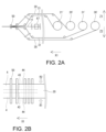
- FIG. 2A is a schematic side view of an upstream portion of an exemplary bag making machine
- FIG. 2B is a partial top view of FIG. 2A
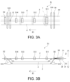
- FIG. 3A is a schematic plan view of a midstream portion of an exemplary bag making machine
- FIG. 3B is a side view of FIG. 3A.
- 4A and 4B show an example point seal portion
- FIG. 4C shows an example spout attachment
- FIG. 5A is a schematic plan view of the downstream portion of an exemplary bag making machine
- FIG. 5B is a side view of FIG. 5A.
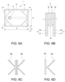
- FIG. 6A shows an exemplary double bag
- FIG. 6A shows an exemplary double bag
- FIG. 6B is a partial cross-sectional view of the overlapping webs
- FIGS. 6C and 6D show an exemplary heat seal bar.
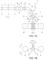
- 7A is a schematic top view of an exemplary gusset forming apparatus
- FIG. 7B is a partial side view of FIG. 7A.
- FIG. 8 is a detailed view of region Q in FIG. 9A is a view taken along line S1 in FIG. 7B
- FIG. 9B is a view taken along line S2 in FIG. 7B
- FIG. 9C is a view taken along line F in FIG. 7A
- FIG. 9D is an enlarged view taken along line J in FIG. 9C
- FIG. 9E is an enlarged view of area G in FIG. 7A.
- FIG. 9A is a schematic top view of an exemplary gusset forming apparatus
- FIG. 7B is a partial side view of FIG. 7A.
- FIG. 10A is a schematic plan view of a gusset forming apparatus according to the related art
- FIG. 10B is a cross-sectional view of a gusset web according to the related art formed by the gusset forming apparatus of FIG. 10A.
- FIG. 1A shows an example double bag 1.
- the double bag 1 has two double bodies 10 facing each other.
- each double body 10 is composed of an outer body 100 and an inner body 101 that are overlapped on each other.
- An accommodation space is formed between the two double bodies 10.
- the two inner bodies 101 face each other and are interposed between the two outer bodies 100.
- the double-layered bag 1 further includes two double-layered gussets 11.
- the two double-layered gussets 11 form a pair, are folded between the two double-layered bodies 10, and extend along both side edges of the double-layered bodies 10.
- the double-layered gussets 11 in this example function as side gussets, and expand the storage space of the bag 1.
- the double gusset 11 consists of an outer gusset portion 110 and an inner gusset portion 111 that are overlapped with each other.
- the outer gusset portion 110 is located on the outside of the bag 1
- the inner gusset portion 111 is located on the inside of the bag 1.
- the double bag 1 further includes a spout 12.
- the spout 12 is attached to one of the double bodies 10. Contents can be filled into or removed from the storage space through the spout 12.
- the double bag 1 has a first seal portion 13 formed along both side edges of the bag 1, and a second seal portion 14 formed along the top and bottom edges of the bag 1.
- each inner body portion 101 is welded to the adjacent outer body portion 100 and inner gusset portion 111, and the outer gusset portion 110 and the inner gusset portion 111 are welded to each other.
- the two inner body portions 101 are welded to each other.
- the double-layered bag 1 further includes a third seal portion 15 that extends at an angle relative to both side edges and top and bottom edges of the bag 1.
- the third seal portion 15 extends obliquely from the end of the folded edge (inner edge) of the double-layered gusset 11 to the first seal portion 13.
- each inner body portion 101 is also welded to the adjacent outer body portion 100 and inner gusset portion 111, and the outer gusset portion 110 and the inner gusset portion 111 are welded to each other.
- the opposing surfaces of the folded outer gusset portion 110 are not welded together.
- FIG. 2A shows a schematic diagram of the upstream portion of an exemplary bag making machine.
- Four original rolls 20', 21', 30', and 31' are installed.
- the original roll 20' is wound with the first outer body web 20 that will form the outer body portion 100 of one of the double body 10 (first double body) of the bag 1.
- the original roll 21' is wound with the first inner body web 21 that will form the inner body portion 101 of the first double body 10.
- the original roll 30' is wound with the second outer body web 30 that will form the outer body portion 100 of the other double body 10 (second double body) of the bag 1.
- the original roll 31' is wound with the second inner body web 31 that will form the inner body portion 101 of the second double body 10.
- the outer body webs 20, 30 have, for example, a laminate structure.
- Each of the outer body webs 20, 30 has a first surface layer, such as a base material layer, and a second surface layer, such as a sealant layer, that has a lower melting point than the first surface layer.
- the inner body webs 21, 31 may be made of a material that has a lower melting point than the base material layer (first surface layer) of the outer body webs 20, 30.
- Other characteristics (for example, thickness) of these webs 20-31 are determined according to the characteristics of the bag 1 to be manufactured (for example, the strength of the bag, etc.). This is similar to Patent Document 1.
- the bag making machine is provided with a pair of overlapping rollers 50 for overlapping the webs 20-31 on each other.
- the webs 20-31 are continuously unwound and fed from their respective original rolls 20'-31' in their longitudinal direction at a constant speed, and then guided to the pair of overlapping rollers 50 via a known accumulator and dancer roller (not shown).
- a dancer roller is provided for each web 20-31, and appropriately converts the feeding of the web 20-31 from continuous feeding to intermittent feeding.
- the web 20-31 is fed intermittently to pass through the pair of overlapping rollers 50.
- the bag making machine is provided with an intermittent feeding device 53 (see Figures 5A and 5B) in its downstream portion for intermittently feeding the web 20-31 in its longitudinal direction.
- the web 20-31 is repeatedly fed and temporarily stopped.
- the webs 20-31 are guided to the overlapping roller pair 50 and overlapped on each other at the overlapping roller pair 50.
- the overlapping order is, from top to bottom, outer body web 20, inner body web 21, inner body web 31, and outer body web 30.
- the high melting point first surface layer (base material layer) of the outer body web 20 faces upward Z1
- the low melting point second surface layer (sealant layer) faces downward Z2 and contacts the inner body web 21.
- the high melting point first surface layer of the outer body web 30 faces downward Z2, and the low melting point second surface layer faces upward Z1 and contacts the inner body web 31.
- the original rolls 20', 30' are appropriately selected so that the webs 20, 30 are wound with their first surface layers facing inward or outward, and an appropriate number of guide members such as inclined plates that change the orientation of the webs 20, 30 are installed in appropriate locations.
- the bag making machine further includes a web forming device 6 (Fig. 7A) which will be described in detail later.
- the web forming device 6 is a gusset forming device which supplies a double gusset web 4 (an example of a double web folded in half) (Figs. 2A and 2B) between the two inner body webs 21, 31 at a position upstream of the overlapping roller pair 50 so that when the webs 20-31 are overlapped with each other at the overlapping roller pair 50, the web is interposed between the inner body webs 21, 31 and positioned in the longitudinal direction of the webs 20-31.
- the web forming device 6 is referred to as a gusset forming device.
- the two double gusset webs 4 are fed from both sides of the width of the web 20-31, redirected in the direction X1, and extend along both sides of the web 20-31.
- the double gusset web 4 is intermittently fed by the intermittent feed device 53 together with the web 20-31 in its longitudinal direction, i.e., in the direction X1.
- This double gusset web 4 constitutes the double gusset 11 of the bag 1.
- the double gusset web 4 is composed of an outer gusset web 40 and an inner gusset web 41, which are folded in half while overlapping each other, as shown in FIG. 6B.
- the outer gusset web 40 constitutes the outer gusset portion 111 of the double gusset 11.
- the outer gusset web 40 like the outer body webs 20 and 30, has, for example, a laminate structure and includes a first surface layer (base material layer) and a second surface layer (sealant layer) having a lower melting point than the first surface layer.
- the inner gusset web 41 constitutes the inner gusset portion of the double gusset 11.
- the inner gusset web 41 is made of a material having a lower melting point than the outer body webs 20 and 30 and the first surface layer (base material layer) of the outer gusset web 40.
- the double gusset web 4 is provided so that its open edge 44 is aligned with the side edge of the web 20-31 and its folded edge 43 is located on the inside.
- Figures 3A and 3B show the midstream portion of an example bag making machine.
- Webs 20, 21 form the first double body 10 of bag 1. Therefore, hereinafter, the overlapped webs 20, 21 may be referred to as the (first) double body web 2.
- the overlapped webs 30, 31 form the second double body 10 of bag 1, and therefore the overlapped webs 30, 31 may be referred to as the (second) double body web 3.
- the bag making machine further includes a spout attachment device 51 that is disposed downstream of the overlapping roller pair 50 and attaches the spout 12 to the first double-body web 2 at each intermittent feed.
- the spout attachment device 51 includes a number of guide rollers 510 for separating the second double body web 3 and the double gusset web 4 from the first double web 2 to provide a temporary separation section where the webs 2, 3, and 4 are temporarily separated.
- FIG. 3B in this example, the web 2 to which the spout 12 is attached is sent horizontally as is, and the webs 3 and 4 are temporarily separated in the downward direction Z2.
- the temporary separation section prevents the webs 3 and 4 from getting in the way when the spout 12 is attached to the web 2.
- the spout attachment device 51 further includes a temporary fastening unit 511, a hole punching unit 512, and an attachment unit 513 in this temporary separation section.
- FIGS. 4A and 4B illustrate region T in FIG. 3A.
- the temporary fastening unit 511 temporarily fastens the webs 20, 21 to each other by heat sealing them at points each time the intermittent feed is temporarily stopped, forming the point seal portion 16. This prevents the webs 20, 21 from shifting relative to each other until the spout 12 is attached to the webs 20, 21 as shown in FIG. 4C.
- the point seal portion 16 is located near the mounting position SA where the spout 12 is mounted. As shown in FIG. 4A, for example, it is preferable that the point seal portion 16 is located near this position SA and is included within an area CS where a horizontal seal, described below, is applied. Also, as shown in FIG. 4B, an annular point seal portion 16 may be formed along the periphery of position SA. The position of the point seal portion 16 in FIG. 4B is the position that will be sealed by the mounting unit 513, described below.
- the web 2-4 is slit along both side edges, and waste resulting from the slitting is removed.
- the point seal portion 16 may be formed in the portion that is removed as waste.
- two or more point seal portions may be provided for one position SA.
- the hole punching unit 512 is disposed one pitch downstream of the intermittent feed from the temporary fastening unit 511.
- the hole punching unit 512 forms a hole 17 (FIG. 4C) for the spout 12 at position SA of the web 2 (i.e., the webs 20, 21 temporarily fastened by the point seal section 16) each time the intermittent feed stops.
- the hole punching unit 512 may form the hole 17 by punching the web 2 with a punch blade. Waste resulting from the formation of the hole 17 is sucked up by a suction unit (not shown).
- the attachment unit 513 is located at a distance of at least one pitch downstream of the intermittent feed from the punching unit 512, and attaches the spout 12 to the web 2 each time the intermittent feed stops. As shown in FIG. 4C, a spout 12 with a flange 120 is used.
- the attachment unit 513 has an annular heat seal block (not shown) that corresponds to the shape of the flange 120.
- the attachment unit 513 inserts the spout 12 into the hole 17 from below, and abuts the heat seal block against the web 20 from above to heat seal the flange 120 to the web 21.
- the second surface layer of the web 20, which has a low melting point is in contact with the web 21, so the web 20 and the web 21 are also heat sealed to each other. Therefore, the spout 12, the web 20, and the web 21 are welded together.
- the spout attachment device 51 further includes a spout detection unit 514 that is provided downstream of the attachment unit 513 within the temporary separation section.
- the spout detection unit 514 uses a sensor (e.g., an optical sensor) not shown to determine whether the spout 12 is properly attached to the web 2.
- the spout detection unit 514 outputs a warning when the spout 12 is not properly attached.
- the webs 2-4 are then overlapped again by the downstream guide roller 510.
- the bag making machine includes a temporary fastening device 52 located downstream of the spout attachment device 51.
- the temporary fastening device 52 temporarily fastens the webs 2-4 to each other by heat sealing, preventing the webs 2-4 from shifting position downstream.
- the temporary fastening position may be within the area where the heat seal is subsequently applied (e.g., area CS in FIG. 4A).
- FIGS. 5A and 5B show schematic views of the downstream portion of an exemplary bag making machine.
- the bag making machine includes an intermittent feed device 53 that intermittently feeds the web 2-4 in its longitudinal direction.
- the intermittent feed device 53 includes at least one drive roller pair 530.
- the drive roller pair 530 nip the web 2-4 and is intermittently rotated by a servo motor, thereby intermittently feeding the web 2-4 in its longitudinal direction (direction X1).
- multiple drive roller pairs 530 are appropriately arranged.
- the bag making machine further includes at least one heat sealing device 54, 56 that is provided downstream of the temporary fastening device 52 and heat seals the web 2-4 at each intermittent feed.
- a vertical sealing device 54 and a horizontal sealing device 56 are provided.
- the vertical sealing device 54 heat seals the web 2-4 in its longitudinal direction each time the intermittent feed stops, forming the first sealed portion 13 (see Figures 1A and 6A) along both side edges of the web 2-4.
- the webs 21, 31, and 41 are made of a low-melting material. Therefore, as is clear from the relative positions of the webs 2-4 in Figure 6B, the four layers of the webs 20, 21, 40, and 41 are welded together, and the four layers of the webs 30, 31, 40, and 41 are welded together.
- the two opposing surfaces of the outer gusset web 40 that is folded in half are the first outer layers with a high melting point, and therefore are not welded to each other. This is also true for the horizontal seal described below.
- the vertical sealing device 54 may heat seal the web 2-4 by clamping it with a heat seal bar.
- a heat seal bar that is longer than twice the vertical dimension H (FIG. 6A) of the bag 1 (corresponding to the feed pitch of the intermittent feed). This allows the vertical sealing device 54 to heat seal the same location at least twice.
- the horizontal sealing device 56 heat seals the web 2-4 in its width direction each time the intermittent feed stops, forming the second sealed portion 14 (see Figures 1A and 6A) across the entire width of the web 2-4. At this time, in areas where the web 4 is not present, the inner body webs 21 and 31 are welded together.
- This exemplary horizontal sealing device 56 also forms the third sealed portion 15 (see Figs. 1A and 6A).
- the horizontal sealing device 56 may use a generally K-shaped heat seal bar 560 as shown in Fig. 6C.
- the horizontal sealing device 56 may use a straight heat seal bar 561 for forming the second sealed portion 14 and a bifurcated heat seal bar 562 for forming the third sealed portion 15 as shown in Fig. 6D.
- the roots of the branches of heat seal bar 560 and heat seal bar 562 heat seal the central portion of webs 2 and 3, and therefore the area where web 4 is not present.
- This area has fewer web layers than the surrounding areas, which creates a step. This step can result in a poor seal. Therefore, to prevent a poor seal, an additional point seal may be applied to this area.
- the bag making machine further includes a vertical cooling device 55 provided downstream of the vertical sealing device 54, and a horizontal cooling device 57 provided downstream of the horizontal sealing device 56. With each intermittent feed, the vertical cooling device 55 cools the first sealing section 13, and the horizontal cooling device 57 cools the second and third sealing sections 14, 15. This cooling makes the sealing surface smooth, providing a well-finished sealing surface.
- the bag making machine further includes a slitting device 58, which is provided downstream of the heat sealing devices 54, 56 and the cooling devices 55, 57 and slits the web 2-4 along both side edges of the webs 2, 3.
- the slitting device 58 includes slitters disposed on both sides of the webs 2, 3.
- Any waste generated during this process is wound up and collected by known means.
- the new edges of the web 2-4 created by the slitting have high linearity. Therefore, both side edges (edges of the first sealed portion 13) of the manufactured bag 1 have high linearity.
- the bag making machine further includes a cross-cutting device 59 that is provided downstream of the slitting device 58 and cross-cuts the web 2-4 in its width direction each time the intermittent feed is stopped to form the double bag 1.
- the cross-cutting device 59 uses a cutter to cross-cut the web 2-4 in its width direction each time the intermittent feed is stopped, thereby obtaining the portion cut out from the web 2-4 as the double bag 1 shown in Figures 1A and 6A.
- This cross-cut position is within the second seal portion 14 on the web 2-4, and more specifically, it is the center line of the horizontal seal area CS, as shown by the symbol CR in Figures 4A and 4B.
- the completed bag 1 is transported by a conveyor (not shown).
- a gusset forming device 6 (an example of a web forming device) for forming and supplying a double gusset web 4 (an example of a double web folded in half) will be described with reference to Figures 7A-9E.
- the illustrated bag making machine has two gusset forming devices 6.
- One gusset forming device 6 supplies the web 4 from one side of the web 20-31 as shown by the arrow R1 in Figure 2B, and the other gusset forming device (not shown) supplies the web 4 from the other side of the web 20-31 as shown by the arrow R2.
- the configurations of both gusset forming devices are symmetrical with respect to the direction X1. Therefore, the former gusset forming device 6 will be described, and a description of the latter gusset forming device will be omitted.
- Two original rolls 40', 41' are installed in the exemplary gusset forming device 6 of Figures 7A and 7B.
- the original roll 40' is wound with an outer gusset web 40 (an example of a first web) that will form the outer gusset portion 110 of the double gusset 11 of the bag 1.
- the original roll 41' is wound with an inner gusset web 41 (an example of a second web) that will form the inner gusset portion 111.
- the original roll 40' is a web 40 with a laminated structure, wound with its first surface layer with a high melting point facing outward and its second surface layer with a low melting point facing inward.
- the gusset forming device 6 has inclined plates 60, 61 provided for each of the webs 40, 41.
- Figures 9A and 9B are views of the arrows S1 and S2 in Figure 7A, respectively.
- the webs 40, 41 are continuously unwound in their longitudinal direction at a constant speed from the original rolls 40', 41', respectively, and fed to the inclined plates 60, 61, where they are redirected from the upward direction Z1 to the horizontal direction Y1 by the inclined plates 60, 61.
- the horizontal direction Y1 is a horizontal direction perpendicular to the feed direction X1 of the webs 20-31 for the double cylinder 10.
- the bag making machine (gusset forming device 6) is equipped with first and second continuous feed devices 690, 691 (shown only in FIG. 8), and the first/second continuous feed devices 690/691 are provided in a section downstream of the inclined plate 60/61 and upstream of the first/second fixed rollers 621/631 with respect to the web 40/41, and continuously feed the web 40/41 in its longitudinal direction.
- Each of the first and second continuous feed devices 690, 691 includes, for example, a pair of drive rollers.
- the gusset forming device 6 further includes a first tension adjustment mechanism 62 for the outer gusset web 40, which is provided downstream of the inclined plate 60, and a second tension adjustment mechanism 63 for the inner gusset web 41, which is provided downstream of the inclined plate 61.
- the webs 40, 41 are redirected in the horizontal direction Y1 by the inclined plates 60, 61, respectively, and then pass through the first and second tension adjustment mechanisms 62, 63.
- the first tension adjustment mechanism 62 converts the feeding of the web 40 from continuous to intermittent feeding, and appropriately controls the tension of the web 40 so that the web 40 is fed intermittently without slack or meandering.
- the second tension adjustment mechanism 63 converts the feeding of the web 41 from continuous to intermittent feeding, and appropriately controls the tension of the web 41 so that the web 41 is fed intermittently without slack or meandering.
- the tension control of the web 40 by the first tension adjustment mechanism 62 and the tension control of the web 41 by the second tension adjustment mechanism 63 are independent of each other.
- the first tension adjustment mechanism 62 of the embodiment is a first dancer mechanism, and includes a first dancer roller 620 that engages with the web 40 to apply tension to the web 40, and two first fixed rollers 621 that are immovably provided upstream and downstream of the first dancer roller 620 to guide the web 40 into engagement with the first dancer roller 620.
- the first tension adjustment mechanism 62 includes a first actuator 622 that supports the first dancer roller 620 for linear movement (left and right in FIG. 8) and urges the first dancer roller 620 against the web 40, a first sensor 623 that detects the position of the first dancer roller 620, and a first controller 624 (consisting of one or more processors) that controls the first continuous feed device 690.
- the first dancer roller 620 moves left and right in FIG. 8 as the web 40 is intermittently fed by the intermittent feed device 53.
- the first sensor 623 detects the position of the first dancer roller 620.
- the first controller 624 then changes the feed speed of the web 40 by the first continuous feed device 690 (the rotation speed of the drive roller pair) based on the detection value of the first sensor 623.
- the first controller 624 keeps the movement of the first dancer roller 620 within a predetermined range and appropriately converts the feed of the web 40 from continuous feed to intermittent feed while adjusting the tension of the web 40.
- the second tension adjustment mechanism 63 of this embodiment is a second dancer mechanism of the same configuration as the first dancer mechanism, and as shown in FIG. 8, includes a second dancer roller 630, a second fixed roller 631, a second actuator 632, a second sensor 633, and a second controller 634 (consisting of one or more processors).
- the second sensor 633 detects the position of the second dancer roller 630, which moves in association with the intermittent feeding of the web 41 by the intermittent feeding device 53.
- the second controller 634 then changes the feeding speed of the web 41 by the second continuous feeding device 691 (e.g., the rotational speed of the continuous feeding roller pair) based on the detection value of the second sensor 633, thereby appropriately converting the feeding of the web 41 from continuous feeding to intermittent feeding while adjusting the tension of the web 41.
- the first and second tension adjustment mechanisms 62, 63 are not limited to dancer mechanisms, and other configurations may be adopted.
- the first and second controllers 624, 634 may be configured as a single controller, and the single controller may control the tensions of the webs 40, 41 independently of each other.
- the webs 40, 41 are intermittently fed by the intermittent feed device 53 as described above.
- the gusset forming device 6 may be equipped with an intermittent feed device (not shown) (consisting of an appropriate number of drive roller pairs and a servo motor with a configuration similar to that of the intermittent feed device 53 of the bag making machine).
- the feed pitch of the intermittent feed is indicated by the symbol P in FIG. 7A, which is set to be equal to the intermittent feed pitch of the webs 20-31, and therefore corresponds to the vertical dimension H of the bag 1 (FIG. 6A).
- the timing of the intermittent feed of both is also set to be equal to each other.
- the gusset forming device 6 further includes a guide member 64 provided downstream of the tension adjustment mechanisms 62, 63, a triangular plate 65 provided immediately downstream of the guide member 64, a pair of crease rollers 66 arranged downstream of the triangular plate 65, a temporary fastening device 67 for the webs 40, 41 provided downstream of the pair of crease rollers 66, and a hole punching device 68 provided downstream of the temporary fastening device 67.
- the guide member 64 in this embodiment is a guide roller. These components 64-68 are arranged in the space between the two inner body webs 21, 31 before overlapping, upstream of the overlapping roller pair 50 ( Figure 2A, etc.).
- the webs 40 and 41 are sent in the order of guide member 64 and triangular plate 65.
- the webs 40 and 41 are sent, they are overlapped at the position of guide member 64 by guide member 64, and are guided in that state to triangular plate 65.
- the second surface layer with a low melting point of the outer gusset web 40 comes into contact with the inner gusset web 41.
- FIG. 9C is a view taken along line F in FIG. 7A
- FIG. 9D is an enlarged view taken along line J in FIG. 9C.
- the webs 40 and 41 overlapped by the guide member 64 are folded in half by the triangular plate 65 along the fold line 42 (FIG. 9C) extending in the longitudinal direction as the webs are fed, and as shown in FIG. 9D, the folded outer gusset web 40 is interposed between the folded inner gusset web 41.
- the webs 40 and 41 then pass through a pair of crease rollers 66, at which point the folding is completed by the pair of crease rollers 66, and the creases are emphasized.
- the webs 40 and 41 are redirected from direction Y1 to direction X1 by passing through the guide member 64 and the triangular plate 65.
- the double gusset web 4 is formed.
- the fold line 42 coincides with the widthwise center line of the webs 40, 41.
- reference numeral 43 in Figs. 7A and 9D indicates the folded edge 43 of the double gusset web 4, which is formed at the position of the fold line 42.
- Reference numeral 44 indicates the open edge of the double gusset web 4. The two opposing surfaces of the folded web 40 become the first surface layer with a high melting point.
- the gusset temporary fastening device 67 temporarily fastens the webs 40, 41 with heat sealing or ultrasonic sealing at each intermittent feed to form the point seal portion 18 (see FIG. 9E, which is an enlarged view of area G in FIG. 7A). This prevents the webs 40, 41 from shifting out of position.
- the position of the point seal portion 18 is, for example, within the horizontal seal area CS described above.
- the hole punching device 68 forms holes 19 (FIG. 9E) for heat sealing in the double gusset web 4 with each intermittent feed.
- the holes 19 are located within the horizontal seal area CS.
- the holes 19 are also formed, for example, on both sides of the cross-cut position CR described above.
- the hole punching device 68 may, for example, punch the web 4 with a punch blade to form the holes 19.
- the hole punching device 68 is equipped with a suction unit (not shown) that sucks up waste generated when forming the holes 19.
- the hole punching device 68 also has a waste detection unit (not shown) that uses a sensor to detect whether waste has not been sucked in and is adhering to the web 4, and outputs a warning when waste is adhering to the web 4.
- the double gusset web 4 is interposed between the inner cylinder webs 21, 31, as described above.
- the open edge 44 is aligned with the side edge of the web 20-31, and the folded edge 43 is located on the inside, as described above.
- the gusset forming device 7 includes triangular plates 70, 71 provided for each of the webs 40, 41, and a disk-shaped rotatable guide plate 72 provided downstream of the triangular plates 70, 71.
- the gusset forming device 7 folds the web 40 in half using the triangular plate 70 and the web 41 in half using the triangular plate 71, and then attempts to align the folded edges of both webs 40, 41 using the guide plate 72.
- a gap 45 is created between the webs 40 and 41 as shown in FIG. 10B, which can cause a problem in that it adversely affects the finish of the double-layered bag 1.
- the gusset forming device 6 of the present application folds the overlapping webs 40, 41 with one triangular plate 65, but upstream, first and second tension adjustment mechanisms 62, 63 control the tension of the webs 40, 41 independently of each other. Therefore, the problem of the prior art that the webs 40, 41 slacken or meander when forming the double gusset web 4 does not occur. Furthermore, because the overlapping webs 40, 41 are folded in half together, the gap 45 of the related art described above does not occur.
- the gusset forming device 6 of the present application can form a double gusset web 4 with a better finish than the conventional and related technologies. Therefore, the bag making machine of the present application equipped with this gusset forming device 6 can provide a high-quality double bag 1.
- the above-mentioned double-layered bag 1 may be used, for example, as an inner bag of a bag-in-box, as in Patent Document 2.
- the webs 20, 30, and 40 may be made of a mono-material film and a medium ink that inhibits heat sealing that is applied partially or entirely to the film.
- the webs 20-41 may be made of paper as a base material and a resin that is partially or entirely coated on the paper. It will be obvious to those skilled in the art that the webs 20-41 are not limited to the configurations and materials exemplified above, so long as they are capable of manufacturing the double-layered bag 1.
- webs 20 and 30 may be formed by slitting a wide web unwound from a single original roll.
- Webs 21 and 31 may also be formed by slitting a wide web unwound from a single original roll.
- the main role of the overlapping roller pair 50 is to organize the transport lines of webs 2, 3, and 4, and not to transport webs 2, 3, and 4. Therefore, the overlapping roller pair 50 does not necessarily need to nip webs 2, 3, and 4, and the nipping force can be very weak or even zero. Conversely, if the nipping force is too strong, there is a possibility that misalignment may occur between the layers in the laminate of webs 2, 3, and 4, so care must be taken.
- the double web formed by the web forming device 6 is used as a double gusset web.
- a double web formed by a web forming device 6 having a similar configuration to the above is used as a double body web folded in half.
- a double-layered bag without gussets is manufactured by forming a double-layered web in half using a web forming device 6, and then undergoing at least a heat sealing process and a cross-cut process using a bag making machine.
- This double-layered bag has an outer body folded in half and an inner body folded in half and interposed between the outer bodies, with the outer body being formed from the second web 41 of the double-layered web, and the inner body being formed from the first web 40 of the double-layered web.
- a material with a high melting point is used for the outer layer of the second web 41
- a material with a low melting point is used for the inner layer
- a material with a low melting point is used for the first web 40.
- the bag making machine of the present application may manufacture double-layered bags having a zipper instead of or in addition to the spout 12.
- the bag making machine of the present application may manufacture double-layered bags with double gussets that function as top and bottom gussets instead of the double gusset 11 that functions as a side gusset as in the above example.
- bag making may be performed using the double gusset web 4 as the top and/or bottom gusset.
- Double-layered bag 10 Double-layered body 11 Double-layered gusset 12 Spout 17 Hole for spout 19 Hole for heat seal 2 First double-layered body web 20 First outer body web 21 First inner body web 3 Second double-layered body web 30 Second outer body web 31 Second inner body web 4 Double-layered gusset web (an example of a double-layered web folded in half) 40 outer gusset web (an example of a first web) 41 Inner gusset web (an example of a second web) 42 Folding line 50 Pair of overlapping rollers 51 Spout mounting device 510 Guide roller 511 Temporary fastening unit 512 Hole punching unit 513 Mounting unit 53 Intermittent feed device 54 Vertical sealing device (an example of a heat sealing device) 56 Horizontal sealing device (an example of a heat sealing device) 59 Cross-cut device 6 Web forming device (gusset forming device) 62 First tension adjustment mechanism (first dancer mechanism) 620 First dancer roller 63 Second tension adjustment mechanism (second dancer mechanism) 630 Second dancer roller
Landscapes
- Making Paper Articles (AREA)
Priority Applications (3)
| Application Number | Priority Date | Filing Date | Title |
|---|---|---|---|
| EP24831661.4A EP4737111A1 (en) | 2023-06-28 | 2024-06-11 | Web forming device and forming method, and bag making machine for double bag |
| CN202480037762.0A CN121335800A (zh) | 2023-06-28 | 2024-06-11 | 片材形成装置和形成方法以及双重袋的制袋机 |
| JP2024550758A JP7693182B2 (ja) | 2023-06-28 | 2024-06-11 | ウェブ形成装置および形成方法、および、二重袋の製袋機 |
Applications Claiming Priority (2)
| Application Number | Priority Date | Filing Date | Title |
|---|---|---|---|
| JP2023-105721 | 2023-06-28 | ||
| JP2023105721 | 2023-06-28 |
Publications (1)
| Publication Number | Publication Date |
|---|---|
| WO2025004795A1 true WO2025004795A1 (ja) | 2025-01-02 |
Family
ID=93938738
Family Applications (1)
| Application Number | Title | Priority Date | Filing Date |
|---|---|---|---|
| PCT/JP2024/021226 Ceased WO2025004795A1 (ja) | 2023-06-28 | 2024-06-11 | ウェブ形成装置および形成方法、および、二重袋の製袋機 |
Country Status (4)
| Country | Link |
|---|---|
| EP (1) | EP4737111A1 (https=) |
| JP (1) | JP7693182B2 (https=) |
| CN (1) | CN121335800A (https=) |
| WO (1) | WO2025004795A1 (https=) |
Citations (10)
| Publication number | Priority date | Publication date | Assignee | Title |
|---|---|---|---|---|
| JPS5085483A (https=) * | 1973-11-29 | 1975-07-10 | ||
| JPS5884752A (ja) * | 1981-11-14 | 1983-05-20 | 中国レジン株式会社 | 弁付包装袋の製造方法およびその装置 |
| JPS6271633A (ja) * | 1985-09-26 | 1987-04-02 | 三和レジン工業株式会社 | 複層袋用シ−ト材の製造装置 |
| JPH02127282A (ja) * | 1988-10-27 | 1990-05-15 | Keiichi Isotani | フレキシブルコンテナ用包装袋の製法 |
| JP2005001114A (ja) * | 2003-06-09 | 2005-01-06 | Totani Corp | プラスチックフィルムの印刷ピッチ矯正装置 |
| JP2005254796A (ja) * | 2004-02-09 | 2005-09-22 | Mitsubishi Gas Chem Co Inc | 脱酸素性袋の製造方法及び装置 |
| JP2016141427A (ja) | 2015-01-30 | 2016-08-08 | エステー産業株式会社 | 収容容器、その製造方法および製造装置 |
| JP2017128017A (ja) * | 2016-01-19 | 2017-07-27 | 西部機械株式会社 | 底ガゼットを有する袋を製袋する製袋機 |
| WO2021117321A1 (ja) * | 2019-12-11 | 2021-06-17 | トタニ技研工業株式会社 | 位置合わせ装置 |
| JP2022007011A (ja) | 2020-06-25 | 2022-01-13 | 株式会社細川洋行 | ガゼット袋及びバッグインボックス |
-
2024
- 2024-06-11 JP JP2024550758A patent/JP7693182B2/ja active Active
- 2024-06-11 WO PCT/JP2024/021226 patent/WO2025004795A1/ja not_active Ceased
- 2024-06-11 EP EP24831661.4A patent/EP4737111A1/en active Pending
- 2024-06-11 CN CN202480037762.0A patent/CN121335800A/zh active Pending
Patent Citations (10)
| Publication number | Priority date | Publication date | Assignee | Title |
|---|---|---|---|---|
| JPS5085483A (https=) * | 1973-11-29 | 1975-07-10 | ||
| JPS5884752A (ja) * | 1981-11-14 | 1983-05-20 | 中国レジン株式会社 | 弁付包装袋の製造方法およびその装置 |
| JPS6271633A (ja) * | 1985-09-26 | 1987-04-02 | 三和レジン工業株式会社 | 複層袋用シ−ト材の製造装置 |
| JPH02127282A (ja) * | 1988-10-27 | 1990-05-15 | Keiichi Isotani | フレキシブルコンテナ用包装袋の製法 |
| JP2005001114A (ja) * | 2003-06-09 | 2005-01-06 | Totani Corp | プラスチックフィルムの印刷ピッチ矯正装置 |
| JP2005254796A (ja) * | 2004-02-09 | 2005-09-22 | Mitsubishi Gas Chem Co Inc | 脱酸素性袋の製造方法及び装置 |
| JP2016141427A (ja) | 2015-01-30 | 2016-08-08 | エステー産業株式会社 | 収容容器、その製造方法および製造装置 |
| JP2017128017A (ja) * | 2016-01-19 | 2017-07-27 | 西部機械株式会社 | 底ガゼットを有する袋を製袋する製袋機 |
| WO2021117321A1 (ja) * | 2019-12-11 | 2021-06-17 | トタニ技研工業株式会社 | 位置合わせ装置 |
| JP2022007011A (ja) | 2020-06-25 | 2022-01-13 | 株式会社細川洋行 | ガゼット袋及びバッグインボックス |
Also Published As
| Publication number | Publication date |
|---|---|
| JPWO2025004795A1 (https=) | 2025-01-02 |
| JP7693182B2 (ja) | 2025-06-17 |
| CN121335800A (zh) | 2026-01-13 |
| EP4737111A1 (en) | 2026-05-06 |
Similar Documents
| Publication | Publication Date | Title |
|---|---|---|
| EP2279857B1 (en) | Bag making machine | |
| CN101291849B (zh) | 薄膜供给设备和具有其的包装设备 | |
| JPH02501816A (ja) | 穿孔された内層を有する積層複合材料およびカートンおよびカートンブランクおよびその製品を製造する方法および装置 | |
| JP7161160B2 (ja) | 位置合わせ装置 | |
| JP7563790B2 (ja) | 縦型充填包装設備 | |
| JP7693182B2 (ja) | ウェブ形成装置および形成方法、および、二重袋の製袋機 | |
| JP4320353B2 (ja) | 製袋機 | |
| JP2013203442A (ja) | 横型製袋充填包装機のオートスプライサー | |
| JP7180932B1 (ja) | 製袋機、および、製袋方法 | |
| JP6121039B1 (ja) | 底ガゼット付き袋体の製造方法 | |
| JP4844937B1 (ja) | ハンドル付きガゼット袋及びその連続製造方法 | |
| WO2026023311A1 (ja) | ウェブ形成装置、ウェブ形成方法、および、製袋機 | |
| JP2004001402A (ja) | 袋の製造装置及び袋の製造方法 | |
| JP5227364B2 (ja) | 開き面を形成する装置、袋の底部、頭部形成装置、袋の製造装置、開き面を形成する方法及びガゼット袋の製造方法 | |
| JPH1191013A (ja) | フラットボトム包装袋の製造方法及び製造装置 | |
| JP2024008497A (ja) | 帯状プラスチックフィルムの搬送ガイド | |
| WO2022180986A1 (ja) | 製袋方法、および、製袋機 | |
| US20240278950A1 (en) | Transverse sealing unit for producing transverse sealing seams in a tubular bag machine | |
| JP2533038B2 (ja) | ヘッダ―付ガゼット袋の製造方法 | |
| JPH10181722A (ja) | インラインシール打抜製袋方法及びその装置 | |
| JP7637423B2 (ja) | 底ガゼット付き袋体の製造方法 | |
| JP7823906B2 (ja) | 包材接続装置 | |
| WO2024154460A1 (ja) | ウェブ重ね装置、および、製袋機 | |
| JP2018150122A (ja) | シート材送り装置 | |
| JPWO2025004795A5 (https=) |
Legal Events
| Date | Code | Title | Description |
|---|---|---|---|
| WWE | Wipo information: entry into national phase |
Ref document number: 2024550758 Country of ref document: JP |
|
| 121 | Ep: the epo has been informed by wipo that ep was designated in this application |
Ref document number: 24831661 Country of ref document: EP Kind code of ref document: A1 |
|
| WWE | Wipo information: entry into national phase |
Ref document number: CN2024800377620 Country of ref document: CN |
|
| WWE | Wipo information: entry into national phase |
Ref document number: 2024831661 Country of ref document: EP |
|
| NENP | Non-entry into the national phase |
Ref country code: DE |
|
| ENP | Entry into the national phase |
Ref document number: 2024831661 Country of ref document: EP Effective date: 20260128 |
|
| ENP | Entry into the national phase |
Ref document number: 2024831661 Country of ref document: EP Effective date: 20260128 |