WO2025004618A1 - コンデンサ、実装基板及びコンデンサの製造方法 - Google Patents
コンデンサ、実装基板及びコンデンサの製造方法 Download PDFInfo
- Publication number
- WO2025004618A1 WO2025004618A1 PCT/JP2024/018741 JP2024018741W WO2025004618A1 WO 2025004618 A1 WO2025004618 A1 WO 2025004618A1 JP 2024018741 W JP2024018741 W JP 2024018741W WO 2025004618 A1 WO2025004618 A1 WO 2025004618A1
- Authority
- WO
- WIPO (PCT)
- Prior art keywords
- external electrode
- internal electrodes
- capacitor
- main surface
- electrode
- Prior art date
- Legal status (The legal status is an assumption and is not a legal conclusion. Google has not performed a legal analysis and makes no representation as to the accuracy of the status listed.)
- Ceased
Links
Images









Classifications
-
- H—ELECTRICITY
- H01—ELECTRIC ELEMENTS
- H01G—CAPACITORS; CAPACITORS, RECTIFIERS, DETECTORS, SWITCHING DEVICES, LIGHT-SENSITIVE OR TEMPERATURE-SENSITIVE DEVICES OF THE ELECTROLYTIC TYPE
- H01G4/00—Fixed capacitors; Processes of their manufacture
- H01G4/002—Details
- H01G4/018—Dielectrics
- H01G4/06—Solid dielectrics
- H01G4/08—Inorganic dielectrics
- H01G4/10—Metal-oxide dielectrics
-
- H—ELECTRICITY
- H01—ELECTRIC ELEMENTS
- H01G—CAPACITORS; CAPACITORS, RECTIFIERS, DETECTORS, SWITCHING DEVICES, LIGHT-SENSITIVE OR TEMPERATURE-SENSITIVE DEVICES OF THE ELECTROLYTIC TYPE
- H01G4/00—Fixed capacitors; Processes of their manufacture
- H01G4/30—Stacked capacitors
-
- H—ELECTRICITY
- H01—ELECTRIC ELEMENTS
- H01G—CAPACITORS; CAPACITORS, RECTIFIERS, DETECTORS, SWITCHING DEVICES, LIGHT-SENSITIVE OR TEMPERATURE-SENSITIVE DEVICES OF THE ELECTROLYTIC TYPE
- H01G4/00—Fixed capacitors; Processes of their manufacture
- H01G4/33—Thin- or thick-film capacitors (thin- or thick-film circuits; capacitors without a potential-jump or surface barrier specially adapted for integrated circuits, details thereof, multistep manufacturing processes therefor)
Definitions
- This disclosure relates to a capacitor, a mounting board, and a method for manufacturing a capacitor.
- a capacitor has been proposed in which multiple bottomed trenches are formed in a conductive silicon substrate, multiple dielectric films are formed on the bottom and side surfaces of the trenches, and electrodes are formed inside the dielectric films to fill the trenches.
- the purpose of this disclosure is to provide a capacitor, a mounting board, and a method for manufacturing a capacitor that can stably obtain a large capacitance.
- the capacitor comprises a conductive substrate having a first main surface and a second main surface opposite the first main surface, a dielectric film formed in the substrate and covering a surface of the substrate including a plurality of through holes extending from the first main surface to the second main surface, inner wall surfaces of the plurality of through holes, and a plurality of internal electrodes filling each of the plurality of through holes inside the dielectric film.
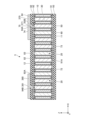
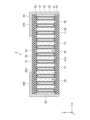
- FIG. 1 is a cross-sectional view showing a capacitor according to a first embodiment.
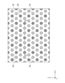
- FIG. 2 is a plan view showing the arrangement of internal electrodes in the capacitor according to the first embodiment.
- FIG. 3 is a flowchart showing a method for manufacturing a capacitor according to the first embodiment.
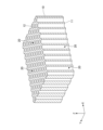
- FIG. 4 is a perspective view (part 1) showing the method for manufacturing the capacitor according to the first embodiment.
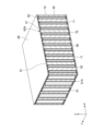
- FIG. 5 is a perspective view (part 2) showing the method for manufacturing the capacitor according to the first embodiment.
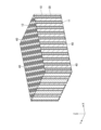
- FIG. 6 is a perspective view (part 3) showing the method for manufacturing the capacitor according to the first embodiment.
- FIG. 7 is a perspective view (part 4) showing the method for manufacturing the capacitor according to the first embodiment.
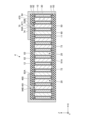
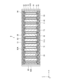
- FIG. 8 is a cross-sectional view showing a capacitor according to the second embodiment.
- FIG. 9 is a plan view showing the arrangement of internal electrodes in a capacitor according to the second embodiment.
- FIG. 10 is a perspective view (part 1) showing a method for manufacturing a capacitor according to the second embodiment.
- FIG. 11 is a perspective view (part 2) showing the method for manufacturing a capacitor according to the second embodiment.
- FIG. 12 is a perspective view (part 3) showing the method for manufacturing the capacitor according to the second embodiment.
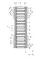
- FIG. 13 is a cross-sectional view showing a capacitor according to the third embodiment.
- FIG. 14 is a cross-sectional view showing a capacitor according to the fourth embodiment.
- FIG. 15 is a cross-sectional view showing a capacitor according to a fifth embodiment.
- FIG. 16 is a cross-sectional view showing a capacitor in accordance with a sixth embodiment.
- FIG. 10 is a perspective view (part 1) showing a method for manufacturing a capacitor according to the second embodiment.
- FIG. 11 is a perspective view (part 2) showing the method for manufacturing a capacitor according to
- FIG. 17 is a front view showing a capacitor according to the seventh embodiment.
- FIG. 18 is a cross-sectional view showing a capacitor according to an eighth embodiment.
- FIG. 19 is a cross-sectional view showing a capacitor according to a ninth embodiment.
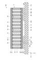
- FIG. 20 is a cross-sectional view showing a mounting board according to the tenth embodiment.
- Fig. 1 is a cross-sectional view showing a capacitor according to the first embodiment.
- Fig. 2 is a plan view showing the arrangement of internal electrodes in the capacitor according to the first embodiment.
- Fig. 1 corresponds to a cross-sectional view taken along line II in Fig. 2.
- the capacitor 1 has a substrate 10, a plurality of through holes 20, a dielectric film 30, a plurality of internal electrodes 50, a plurality of internal electrodes 60, an external electrode 70, an external electrode 80, an insulating layer 91, and an insulating layer 92. Note that the external electrode 80 and the insulating layer 92 are omitted in Figure 2.
- the substrate 10 is conductive.
- the substrate 10 includes, for example, silicon (Si), hafnium (Hf), lanthanum (La), niobium (Nb), tantalum (Ta), titanium (Ti), or zirconium (Zr).
- the substrate 10 may be composed of Si, Hf, La, Nb, Ta, Ti, or Zr. When Si is used as the material of the substrate 10, the substrate 10 is doped with impurities.
- the substrate 10 has a main surface 11 and a main surface 12 opposite to the main surface 11. In one example, the main surface 11 and the main surface 12 are perpendicular to the Z-axis direction, the main surface 11 is the lower surface, and the main surface 12 is the upper surface.
- the main surface 11 is an example of a first main surface
- the main surface 12 is an example of a second main surface.
- the shape of the substrate 10 is, for example, approximately rectangular.
- the dimension of the substrate 10 in the X-axis direction is 100 ⁇ m to 5000 ⁇ m
- the dimension in the Y-axis direction is 50 ⁇ m to 3000 ⁇ m
- the dimension in the Z-axis direction is 10 ⁇ m to 3000 ⁇ m.
- the plurality of through holes 20 are formed in the substrate 10.
- the through holes 20 penetrate the substrate 10 from the main surface 11 to the main surface 12.
- the cross-sectional shape of the through holes 20 perpendicular to the longitudinal direction is, for example, a circle with a diameter of 0.01 ⁇ m to 20 ⁇ m.
- the plurality of through holes 20 are arranged in a triangular lattice shape in a planar view.
- the plurality of through holes 20 are arranged in a regular triangular lattice shape with one side of the smallest unit triangle aligned in the X-axis direction.
- the pitch of the through holes 20 is, for example, 0.02 ⁇ m to 50 ⁇ m.
- the cross-sectional shape of the through holes 20 perpendicular to the longitudinal direction does not have to be circular, and may be, for example, rectangular or elliptical, but a circular shape is preferable from the viewpoint of ease of processing.
- the plurality of through holes 20 can be arranged in various ways in a planar view, but when they are arranged in a triangular lattice shape, for example, it is preferable that the cross-sectional shape of the through holes 20 perpendicular to the longitudinal direction be hexagonal rather than circular, considering the opposing faces of each other.
- the shape of the cross section perpendicular to the longitudinal direction of the through holes 20 can be set appropriately depending on the arrangement of the multiple through holes 20 in a plan view and the ease of processing.
- the dielectric film 30 covers the surface of the substrate 10.
- the surface of the substrate 10 includes the inner wall surface of the through hole 20.
- the dielectric film 30 is, for example, an oxide film, a nitride film, or an oxynitride film containing the same elements as the substrate 10.
- the substrate 10 is a conductive Si substrate
- the dielectric film 30 is a Si oxide film, a nitride film, or an oxynitride film.
- the thickness of the dielectric film 30 is, for example, 1 nm to 1000 nm.
- the dielectric film 30 is homogeneous and has a uniform thickness, so that it can be a capacitor with little variation in capacitance and good voltage resistance characteristics.
- Each of the multiple internal electrodes 50 fills one through hole 20 inside the dielectric film 30.
- each of the multiple internal electrodes 60 fills another through hole 20 inside the dielectric film 30.
- two internal electrodes 50 and one internal electrode 60 are repeatedly arranged between the multiple through holes 20 arranged in a direction parallel to the side of the smallest unit triangle of the regular triangular lattice formed by the multiple through holes 20.
- the direction parallel to the side of the smallest unit triangle of the regular triangular lattice formed by the multiple through holes 20 is the X-axis direction and two directions inclined by 60° clockwise or counterclockwise from the X-axis direction in the XY plane.
- the internal electrodes 50 and 60 include, for example, nickel (Ni), copper (Cu), palladium (Pd), platinum (Pt), silver (Ag), gold (Au), ruthenium (Ru), tungsten (W), molybdenum (Mo), titanium (Ti), or conductive silicon.
- the internal electrodes 50 and 60 may include an alloy material containing one or more of these metal elements.
- the internal electrodes 50 and 60 may include other metal elements.
- the internal electrodes 50 and 60 are an example of a first internal electrode, and the internal electrodes 60 are an example of a second internal electrode.
- the arrangement of the multiple through holes 20 in a plan view is such that the first internal electrode and the second internal electrode have a large opposing area.
- the internal electrode 50, which is a part of the first internal electrode, and the internal electrode 60, which is a part of the second internal electrode may be arranged at two diagonal points of each unit lattice of a square lattice, a rectangular lattice, or a rhombic lattice.
- An asymmetric arrangement such as a parallelepiped lattice is also acceptable, but a symmetric arrangement is preferable in order to achieve uniform capacitor characteristics.
- the insulating layer 91 covers the main surface 11 of the substrate 10 from below, sandwiching the dielectric film 30 therebetween.
- the insulating layer 91 further covers the lower surfaces of the internal electrodes 50 and 60.
- the insulating layer 92 covers the main surface 12 of the substrate 10 from above, sandwiching the dielectric film 30 therebetween.
- the insulating layer 92 further covers the upper surfaces of the internal electrodes 50 and 60.
- the material of the insulating layer 91 and the insulating layer 92 is, for example, a resin material such as polyimide, or an inorganic material such as silicon oxide (SiO 2 ), silicon nitride (SiN), or silicon oxynitride (SiON).
- the material of the insulating layer 91 and the insulating layer 92 may be an insulating material other than these.
- the insulating layer 91 and the insulating layer 92 can protect the substrate 10, the dielectric film 30, the internal electrodes 50, and the internal electrodes 60 from the external environment.
- the thickness of the insulating layer 91 and the insulating layer 92 is, for example, 10 nm to 5000 nm.
- a plurality of contact holes 91A are formed in the insulating layer 91, penetrating the insulating layer 91 in the Z-axis direction and reaching the underside of the internal electrode 50. At least a portion of the underside of the internal electrode 50 is exposed from each of the contact holes 91A.
- a plurality of contact holes 92A are formed in the insulating layer 92, penetrating the insulating layer 92 in the Z-axis direction and reaching the upper surface of the internal electrode 60. At least a portion of the upper surface of the internal electrode 60 is exposed from each of the contact holes 92A.
- the external electrode 70 is provided so as to contact the lower surface of the insulating layer 91.
- the external electrode 70 has a plurality of lead-out portions 71 each located in the contact hole 91A.
- the upper end of the lead-out portion 71 contacts the internal electrode 50, and the external electrode 70 is electrically connected to the plurality of internal electrodes 50.
- the external electrode 80 is provided so as to contact the upper surface of the insulating layer 92.
- the external electrode 80 has a plurality of lead-out portions 81 each located in the contact hole 92A. The lower end of the lead-out portion 81 contacts the internal electrode 60, and the external electrode 80 is electrically connected to the plurality of internal electrodes 60.
- the external electrode 70 and the external electrode 80 include, for example, copper (Cu), nickel (Ni), tin (Sn), palladium (Pd), platinum (Pt), silver (Ag), or gold (Au).
- the external electrode 70 and the external electrode 80 may include an alloy material including one or more of these metal elements.
- the external electrode 70 and the external electrode 80 may include other metal elements.
- the thickness of the external electrode 70 and the external electrode 80 is, for example, 100 nm to 10,000 nm.
- the lead-out portion 71 and the lead-out portion 81 may be formed independently of the external electrode 70 and the external electrode 80, respectively.
- the lead-out portion 71 and the lead-out portion 81 may be a part of the internal electrode 50 and the internal electrode 60, respectively, and may be made of the same material as the internal electrode 50 and the internal electrode 60, respectively.
- the lead-out portion 71 and the lead-out portion 81 are conductor portions independent of the internal electrode 50 and the external electrode 70, and the internal electrode 60 and the external electrode 80, respectively, and may be made of a different material from each of them, but if the thermal shrinkage rate of the material is taken into consideration, it is preferable that the lead-out portion 71 and the lead-out portion 81 are made of the same material as either or both of the materials.
- the internal electrode 50 functions as a first internal electrode of a first polarity
- the internal electrode 60 functions as a second internal electrode of a second polarity.
- the external electrode 70 is an example of a first external electrode
- the external electrode 80 is an example of a second external electrode.
- FIG. 3 is a flowchart showing the method for manufacturing the capacitor according to the first embodiment.
- FIG. 4 to FIG. 7 are perspective views showing the method for manufacturing the capacitor according to the first embodiment.
- a substrate 10 having a main surface 11 and a main surface 12 is prepared, and a plurality of through holes 20 are formed in the substrate 10 (step S1).
- a resist mask having openings exposing the areas where the through holes 20 are to be formed is formed on the main surface 11 or the main surface 12 by photolithography, and deep reactive ion etching (RIE) is performed using this resist mask.
- the deep RIE can be performed by, for example, the Bosch method.
- a wet etching process such as a photoassisted electrolytic etching method may be used. When the wet etching process is used, costs can be reduced compared to the Bosch method.
- the Bosch method uses greenhouse gases, but the wet etching process does not require greenhouse gases, so the burden on the global environment can be reduced.
- a dielectric film 30 is formed on the surface of the substrate 10, including the inner wall surface of the through hole 20 (step S2).
- the dielectric film 30 is formed, for example, by thermally oxidizing the substrate 10.
- an oxide film containing the same elements as the substrate 10 is formed as the dielectric film 30.
- thermal nitridation or thermal oxynitridation of the substrate 10 may be performed.
- thermal nitridation of the substrate 10 a nitride film containing the same elements as the substrate 10 is formed as the dielectric film 30, and by thermal oxynitridation of the substrate 10, an oxynitride film containing the same elements as the substrate 10 is formed as the dielectric film 30.
- the internal electrodes 50 and 60 that fill the through hole 20 on the inside of the dielectric film 30 are formed (step S3).
- the internal electrodes 50 and 60 can be formed, for example, by a plating method.
- the internal electrodes 50 and 60 may be formed by filling and firing a conductive paste.
- an insulating layer 91 is formed to cover the main surface 11 of the substrate 10 from below with the dielectric film 30 sandwiched therebetween, and an insulating layer 92 is formed to cover the main surface 12 of the substrate 10 from above with the dielectric film 30 sandwiched therebetween (step S4).
- a plurality of contact holes 91A are formed in the insulating layer 91, and a plurality of contact holes 92A are formed in the insulating layer 92.
- the insulating layers 91 and 92 can be formed, for example, by chemical vapor deposition (CVD) method.
- the contact holes 91A and 92A can be formed, for example, by etching using a mask.
- an external electrode 70 having an extension 71 is formed so as to contact the lower surface of the insulating layer 91, and an external electrode 80 having an extension 81 is formed so as to contact the upper surface of the insulating layer 92 (step S5).
- the external electrodes 70 and 80 can be formed, for example, by a sputtering method.
- the capacitor 1 according to the first embodiment can be manufactured.
- the external electrode 70 may be formed after the insulating layer 91 is formed, and the insulating layer 92 and the external electrode 80 may be formed in this order after the external electrode 70 is formed.
- the external electrode 80 may be formed after the insulating layer 92 is formed, and the insulating layer 91 and the external electrode 70 may be formed in this order after the external electrode 80 is formed.
- a plurality of through holes 20 penetrate the substrate 10, and a dielectric film 30 covers the surface of the substrate 10, including the inner wall surfaces of the plurality of through holes 20.
- a dielectric film 30 can be formed by thermal oxidation, thermal nitridation, or thermal oxynitridation of the substrate 10.
- the through holes 20 the area in which the substrate 10 and the internal electrode 50 or the internal electrode 60 face each other becomes larger than when a bottomed hole is formed instead of the through holes 20. For this reason, a large capacity can be obtained.
- a thin dielectric film 30 can be formed with a stable thickness by thermal oxidation, thermal nitridation, or thermal oxynitridation.
- the oxidizing gas or nitriding gas used to form the dielectric film 30 can be uniformly supplied into the through holes 20.
- the through holes 20 can be easily filled with a conductive material without forming voids (voids). Therefore, the capacitor 1 can easily and stably obtain a large capacity.
- the dielectric film 30, the conductive substrate 10, and the dielectric film 30 are sandwiched in this order between the adjacent internal electrodes 50 of the first polarity and the internal electrodes 60 of the second polarity. This ensures a high degree of symmetry between the internal electrodes 50 of the first polarity and the internal electrodes 60 of the second polarity. Therefore, when the material of the internal electrodes 50 and the material of the internal electrodes 60 are the same, the effect of polarity on the characteristics of the capacitor 1 can be suppressed.
- the dielectric film 30 is a silicon nitride film
- the barrier properties of the substrate 10 can be improved compared to when the dielectric film 30 is a silicon oxide film.
- the dielectric film 30 is formed by thermal oxidation, thermal nitridation, or thermal oxynitridation of the substrate 10, it is easier to reduce manufacturing costs and time than when the dielectric film 30 is formed by atomic layer deposition (ALD) or CVD.
- ALD atomic layer deposition
- the equivalent series inductance (ESL) and equivalent series resistance (ESR) can be reduced compared to when they are arranged inside a bottomed hole.
- Fig. 8 is a cross-sectional view showing a capacitor according to the second embodiment.
- Fig. 9 is a plan view showing the arrangement of the internal electrodes in the capacitor according to the second embodiment.
- Fig. 8 corresponds to a cross-sectional view taken along line VIII-VIII in Fig. 9.
- the capacitor 2 has a substrate 10, a plurality of through holes 20, a dielectric film 30, a plurality of internal electrodes 40, an external electrode 70, an external electrode 80, and a plurality of insulating layers 95. Note that the external electrode 70 and the insulating layer 95 are omitted in Figure 9.
- the configuration of the substrate 10 and the through hole 20 is the same as in the first embodiment.
- the configuration of the dielectric film 30 is the same as in the first embodiment, except that it is not formed on the main surface 12 of the substrate 10.
- Each of the multiple internal electrodes 40 fills one through hole 20 inside the dielectric film 30.
- the internal electrodes 40 are made of, for example, the same material as the internal electrodes 50 and 60.
- Each of the multiple insulating layers 95 covers the upper surface of the internal electrode 40.
- the insulating layers 95 are made of, for example, the same material as the insulating layers 91 and 92.
- the thickness of the insulating layers 95 is, for example, 10 nm to 5000 nm.
- the external electrode 70 is provided so as to contact the main surface 12 of the substrate 10 and the upper surfaces of the multiple insulating layers 95.
- the external electrode 70 is electrically connected to the substrate 10.
- the external electrode 80 is provided so as to contact the lower surfaces of the multiple internal electrodes 40 and the lower surface of the dielectric film 30.
- the external electrode 80 is electrically connected to the internal electrode 40.
- voltages of different polarities are applied between the external electrode 70 and the external electrode 80.
- the conductive substrate 10 functions as an internal electrode of a first polarity
- the internal electrode 40 functions as an internal electrode of a second polarity.
- Figures 10 to 12 are perspective views showing the method for manufacturing the capacitor according to the second embodiment.
- the substrate 10 is prepared, and a plurality of through holes 20 are formed in the substrate 10 (see FIG. 4).
- a dielectric film 30 is formed on the surface of the substrate 10, including the inner wall surfaces of the through holes 20.
- an internal electrode 40 is formed to fill the through holes 20 inside the dielectric film 30.
- the internal electrode 40 can be formed by, for example, a plating method.
- the internal electrode 40 may also be formed by filling and firing a conductive paste.
- the portion of the dielectric film 30 covering the main surface 12 of the substrate 10 is removed by etching. As a result, the main surface 12 of the substrate 10 is exposed.
- a plurality of insulating layers 95 are formed to cover the upper surface of the internal electrode 40.
- the plurality of insulating layers 95 can be formed, for example, by forming and processing the main surface 12 of the insulating layer that will become the plurality of insulating layers 95 and the upper surface of the internal electrode 40 as a whole.
- an external electrode 70 is formed so as to contact the main surface 12 of the substrate 10 and the upper surface of the insulating layer 95, and an external electrode 80 is formed so as to contact the lower surfaces of the multiple internal electrodes 40 and the lower surface of the dielectric film 30.
- the capacitor 2 according to the second embodiment can be manufactured.
- the capacitor 2 according to the second embodiment can easily and stably obtain a large capacity, just like the first embodiment.
- a third embodiment differs from the first embodiment mainly in the configuration of the external electrodes.
- Fig. 13 is a cross-sectional view showing a capacitor according to the third embodiment.
- the capacitor 3 has, in addition to the configuration of the capacitor 1, a collector electrode 72, a collector electrode 82, an insulating layer 93, an insulating layer 94, and a connection portion 74.
- the capacitor 3 has an external electrode 370 and an external electrode 380 instead of the external electrode 70 and the external electrode 80.
- the configurations of the substrate 10, through hole 20, dielectric film 30, internal electrode 50, internal electrode 60, and insulating layer 91 are the same as those in the first embodiment.
- the configuration of the insulating layer 92 is the same as that in the first embodiment, except that in addition to the multiple contact holes 92A, a contact hole 92B is formed.
- the contact hole 92B penetrates the insulating layer 92 in the Z-axis direction and reaches the top surface of one of the internal electrodes 50. At least a portion of the top surface of the internal electrode 50 is exposed from the contact hole 92B.
- the collector electrode 72 is provided so as to contact the lower surface of the insulating layer 91.
- the collector electrode 72 has a plurality of lead-out portions 73 each located in the contact hole 91A.
- the upper end of the lead-out portion 73 contacts the internal electrode 50, and the collector electrode 72 is electrically connected to the internal electrode 50.
- the collector electrode 82 is provided so as to contact the upper surface of the insulating layer 92.
- the collector electrode 82 has a plurality of lead-out portions 83 each located in the contact hole 92A. The lower end of the lead-out portion 83 contacts the internal electrode 60, and the collector electrode 82 is electrically connected to the internal electrode 60.
- connection portion 74 is provided away from the collector electrode 82 so as to contact the upper surface of the insulating layer 92.
- the connection portion 74 has a lead-out portion 75 located in the contact hole 92B. The lower end of the lead-out portion 75 contacts the internal electrode 50, and the connection portion 74 is electrically connected to the internal electrode 50.
- the collector electrodes 72, 82, and connection parts 74 are made of, for example, the same material as the external electrodes 70 and 80.
- the thicknesses of the collector electrodes 72, 82, and connection parts 74 are, for example, 10 nm to 5000 nm.
- Insulating layer 93 covers the lower surface of insulating layer 91 from below, sandwiching collector electrode 72 therebetween.
- Insulating layer 94 covers the upper surface of insulating layer 92 from above, sandwiching collector electrode 82 and connection portion 74 therebetween.
- Insulating layers 93 and 94 are made of, for example, the same material as insulating layers 91 and 92.
- the thickness of insulating layers 93 and 94 is, for example, 10 nm to 5000 nm.
- Insulating layer 94 is formed with contact hole 94A, which penetrates insulating layer 94 in the Z-axis direction and reaches the top surface of connection portion 74, and contact hole 94B, which penetrates insulating layer 94 in the Z-axis direction and reaches the top surface of collector electrode 82. At least a portion of the top surface of connection portion 74 is exposed from contact hole 94A, and at least a portion of the top surface of collector electrode 82 is exposed from contact hole 94B.
- the external electrode 370 is provided so as to contact the upper surface of the insulating layer 94.
- the external electrode 370 has a lead portion 371 located in the contact hole 94A. The lower end of the lead portion 371 is in contact with the connection portion 74, and the external electrode 370 is electrically connected to the internal electrode 50 via the connection portion 74.
- the multiple internal electrodes 50 are electrically connected to the collecting electrode 72. Therefore, the external electrode 370 is electrically connected to the multiple internal electrodes 50.
- the external electrode 380 is provided so as to contact the upper surface of the insulating layer 94.
- the external electrode 380 has a lead portion 381 located in the contact hole 94B.
- the lower end of the lead portion 381 is in contact with the collecting electrode 82, and the external electrode 380 is electrically connected to the multiple internal electrodes 60 via the collecting electrode 82.
- the external electrode 370 and the external electrode 380 are, for example, made of the same material as the external electrode 70 and the external electrode 80.
- the third embodiment can achieve the same effects as the first embodiment.
- the capacitor 3 according to the third embodiment is mounted on a circuit board, for example, with the main surface 12 facing the circuit board.
- a fourth embodiment differs from the third embodiment mainly in the configuration of the external electrodes.
- Fig. 14 is a cross-sectional view showing a capacitor according to the fourth embodiment.
- the capacitor 4 according to the fourth embodiment has an external electrode 470 and an external electrode 480 instead of the external electrode 370 and the external electrode 380.
- the external electrode 470 is in contact with the upper surface of the insulating layer 94 and is provided so as to cover the +X side surface of the substrate 10 from above the dielectric film 30.
- the external electrode 470 has a lead portion 471 located in the contact hole 94A. The lower end of the lead portion 471 is in contact with the connection portion 74, and the external electrode 470 is electrically connected to the internal electrode 50.
- the external electrode 480 is in contact with the upper surface of the insulating layer 94 and is provided so as to cover the -X side surface of the substrate 10 from above the dielectric film 30.
- the external electrode 480 has a lead portion 481 located in the contact hole 94B. The lower end of the lead portion 481 is in contact with the collecting electrode 82, and the external electrode 480 is electrically connected to the internal electrode 60.
- the external electrodes 470 and 480 are made of, for example, the same material as the external electrodes 70 and 80.
- the fourth embodiment can also provide the same effects as those of the third embodiment. Furthermore, in the fourth embodiment, when a fluid conductive adhesive is used for mounting to a circuit board, the conductive adhesive can be made to wet and spread over a wide area of the external electrodes 470 and 480, resulting in higher mounting reliability.
- a fifth embodiment differs from the fourth embodiment mainly in the configuration of the external electrodes.
- Fig. 15 is a cross-sectional view showing a capacitor according to the fifth embodiment.
- the capacitor 5 according to the fifth embodiment has an external electrode 570 and an external electrode 580 instead of the external electrode 470 and the external electrode 480.
- the capacitor 5 has a connection portion 84 in addition to the configuration of the capacitor 4.
- a contact hole 91B is formed in the insulating layer 91.
- the contact hole 91B penetrates the insulating layer 91 in the Z-axis direction and reaches the lower surface of one internal electrode 60. At least a part of the lower surface of the internal electrode 60 is exposed from the contact hole 91B.
- the connection portion 84 is provided away from the collecting electrode 72 so as to contact the lower surface of the insulating layer 91.
- the connection portion 84 has a lead portion 85 located in the contact hole 91B. The upper end of the lead portion 85 contacts the internal electrode 60, and the connection portion 84 is electrically connected to the internal electrode 60.
- Insulating layer 93 is formed with contact hole 93A, which penetrates insulating layer 93 in the Z-axis direction and reaches the underside of collector electrode 72, and contact hole 93B, which penetrates insulating layer 93 in the Z-axis direction and reaches the underside of connection portion 84. At least a portion of the underside of collector electrode 72 is exposed from contact hole 93A, and at least a portion of the underside of connection portion 84 is exposed from contact hole 93B.
- the external electrode 570 has a portion in contact with the lower surface of the insulating layer 93 and a lead portion 576 located in the contact hole 93A in addition to the configuration of the external electrode 470.
- the upper end of the lead portion 576 is in contact with the collector electrode 72, and the external electrode 570 is electrically connected to the internal electrode 50 via the collector electrode 72 in addition to the connection portion 74.
- the external electrode 580 has a portion in contact with the lower surface of the insulating layer 93 and a lead portion 586 located in the contact hole 93B in addition to the configuration of the external electrode 480.
- the upper end of the lead portion 586 is in contact with the connection portion 84, and the external electrode 580 is electrically connected to the internal electrode 60 via the connection portion 84 in addition to the collector electrode 82.
- the external electrode 570 and the external electrode 580 are made of, for example, the same material as the external electrode 70 and the external electrode 80.
- the capacitor 3 according to the fifth embodiment can be mounted on a circuit board, for example, with either the main surface 11 or the main surface 12 facing the circuit board.
- a sixth embodiment differs from the fifth embodiment mainly in the configuration of the external electrodes.
- Fig. 16 is a cross-sectional view showing a capacitor according to the sixth embodiment.
- the capacitor 6 according to the sixth embodiment has an external electrode 370 and an external electrode 670 instead of the external electrode 570, and an external electrode 380 and an external electrode 680 instead of the external electrode 580.
- the external electrode 670 is provided so as to contact the lower surface of the insulating layer 93, and has a lead portion 676 located in the contact hole 93A. The upper end of the lead portion 676 contacts the collector electrode 72, and the external electrode 670 is electrically connected to the internal electrode 50 via the collector electrode 72.
- the external electrode 680 is provided so as to contact the lower surface of the insulating layer 93, and has a lead portion 686 located in the contact hole 93B.
- the upper end of the lead portion 686 contacts the connection portion 84, and the external electrode 680 is electrically connected to the internal electrode 60 via the connection portion 84.
- the external electrode 670 and the external electrode 680 are made of, for example, the same material as the external electrode 70 and the external electrode 80.
- a seventh embodiment differs from the fifth embodiment mainly in the configuration of the external electrodes.
- Fig. 17 is a front view showing the capacitor according to the seventh embodiment.
- the capacitor 7 according to the seventh embodiment has an external electrode 770 and an external electrode 780 instead of the external electrode 570 and the external electrode 580.
- the external electrode 770 has a lead portion 771 located in the contact hole 94A and a lead portion 772 located in the contact hole 93A. The lower end of the lead portion 771 contacts the connection portion 74, and the upper end of the lead portion 772 contacts the collector electrode 72, and the external electrode 770 is electrically connected to the internal electrode 50.
- the external electrode 780 has a lead portion 781 located in the contact hole 94B and a lead portion 782 located in the contact hole 93B. The lower end of the lead portion 781 contacts the collector electrode 82, and the upper end of the lead portion 782 contacts the connection portion 84, and the external electrode 780 is electrically connected to the internal electrode 60.
- external electrode 770 and external electrode 780 have portions covering two side surfaces perpendicular to the Y-axis direction. That is, external electrode 770 covers five surfaces of substrate 10: the +Z side surface (principal surface 12), the -Z side surface (principal surface 11), the +X side surface, the +Y side surface, and the -Y side surface. External electrode 780 covers five surfaces of substrate 10: the +Z side surface (principal surface 12), the -Z side surface (principal surface 11), the -X side surface, the +Y side surface, and the -Y side surface.
- the +Y side surface and the -Y side surface of substrate 10 are covered by dielectric film 30, and external electrode 770 and external electrode 780 cover the +Y side surface and the -Y side surface of substrate 10 from above dielectric film 30.
- the +Y side surface and the -Y side surface of the substrate 10 may be covered with a dielectric film 30 and an insulating layer made of the same material as the insulating layers 91 and 92.
- the external electrodes 770 and 780 are made of, for example, the same material as the external electrodes 70 and 80.
- the seventh embodiment can also provide the same effects as those of the fifth embodiment. Furthermore, in the seventh embodiment, when a fluid conductive adhesive is used for mounting to a circuit board, the conductive adhesive can be made to wet and spread over a wide area of the external electrodes 770 and 780, resulting in higher mounting reliability.
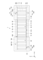
- Fig. 18 is a cross-sectional view showing a capacitor according to the eighth embodiment.
- the capacitor 8 according to the eighth embodiment has, in addition to the configuration of the capacitor 1, a collector electrode 72, a collector electrode 82, an insulating layer 93, and an insulating layer 94, as in the third embodiment. Furthermore, the capacitor 8 according to the eighth embodiment has an external electrode 870 and an external electrode 880 instead of the external electrode 70 and the external electrode 80.
- the multiple internal electrodes 50 and the collector electrode 72 are exposed from the side surface of the +X side of the substrate 10, and the multiple internal electrodes 60 and the collector electrode 82 are exposed from the side surface of the -X side of the substrate 10.
- the external electrode 870 is in contact with the multiple internal electrodes 50 and the collector electrode 72 exposed from the side surface of the +X side of the substrate 10.
- the external electrode 880 is in contact with the multiple internal electrodes 60 and the collector electrode 82 exposed from the side surface of the -X side of the substrate 10. Therefore, the external electrode 870 is electrically connected to the multiple internal electrodes 50 via the collector electrode 72, and the external electrode 880 is electrically connected to the multiple internal electrodes 60 via the collector electrode 82.
- the external electrode 870 and the external electrode 880 have a portion that is in contact with the upper surface of the insulating layer 94.
- the external electrode 870 and the external electrode 880 are made of, for example, the same material as the external electrode 70 and the external electrode 80.
- the capacitor 8 according to the eighth embodiment is mounted on a circuit board, for example, with the main surface 12 facing the circuit board. Furthermore, when a fluid conductive adhesive is used for mounting on the circuit board, the conductive adhesive can be made to wet and spread over a wide area of the external electrodes 870 and 880, resulting in higher mounting reliability.
- a ninth embodiment will be described.
- the ninth embodiment differs from the eighth embodiment mainly in the configuration of the external electrodes.
- Fig. 19 is a cross-sectional view showing a capacitor according to the ninth embodiment.
- the capacitor 9 according to the ninth embodiment has external electrodes 970 and 980 instead of external electrodes 870 and 880.
- the external electrodes 970 and 980 do not have any portions that contact the upper surface of the insulating layer 94.
- the tenth embodiment relates to a mounting board having a capacitor.
- Fig. 20 is a cross-sectional view showing the mounting board according to the tenth embodiment.
- the mounting board 100 has a circuit board 110 and the capacitor 3 according to the third embodiment.
- the circuit board 110 is provided with a connection land 101 and a connection land 102.
- the capacitor 3 is mounted on the circuit board 110.
- An external electrode 370 is joined to the connection land 101, and an external electrode 380 is joined to the connection land 102.
- the mounting board 100 can be mounted on various electronic devices. Examples of electronic devices equipped with the mounting board 100 include smartphones, mobile phones, tablet terminals, and game consoles.
- capacitors 1, 2, 4, 5, 6, 7, 8, or 9 may be used instead of capacitor 3.
- the shape of the cross section perpendicular to the longitudinal direction of the through hole 20 is not limited to a circle, and may be other shapes such as a square, rectangular, triangular, hexagonal, or zigzag shape.
- the multiple through holes 20 may be arranged in other layouts such as a square lattice.
- the arrangement of the multiple internal electrodes 50 and the multiple internal electrodes 60 arranged in the closest packing direction in a plan view perpendicular to the main surface 12 is not limited to the above example, and for example, one internal electrode 50 and one internal electrode 60 may be arranged repeatedly.
- the through hole 20 may have a tapered inner wall surface whose opening area narrows as it moves away from the main surface 11, or may have a tapered inner wall surface whose opening area narrows as it moves away from the main surface 12.
- a conductive substrate having a first main surface and a second main surface opposite to the first main surface; A plurality of through holes formed in the base material and penetrating from the first main surface to the second main surface; a dielectric film covering a surface of the base material including inner wall surfaces of the plurality of through holes; a plurality of internal electrodes filling the plurality of through holes on the inside of the dielectric film; A capacitor having
- the plurality of internal electrodes are a plurality of first internal electrodes of a first polarity; a plurality of second internal electrodes of a second polarity different from the first polarity;
- ⁇ 3> a first external electrode electrically connected to the plurality of first internal electrodes; a second external electrode electrically connected to the plurality of second internal electrodes;
- ⁇ 4> The capacitor described in ⁇ 2> or ⁇ 3>, wherein two of the first internal electrodes and one of the second internal electrodes are repeatedly arranged between the plurality of first internal electrodes and the plurality of second internal electrodes arranged in a close-packed direction in a planar view perpendicular to the second main surface.
- ⁇ 6> The capacitor according to any one of ⁇ 1> to ⁇ 5>, wherein the dielectric film is an oxide film, a nitride film, or an oxynitride film containing the same element as the substrate.
- ⁇ 7> The capacitor according to any one of ⁇ 1> to ⁇ 6>, wherein the substrate contains silicon, hafnium, lanthanum, niobium, tantalum, titanium, or zirconium.
- ⁇ 8> A circuit board; The capacitor according to any one of ⁇ 1> to ⁇ 7>, which is mounted on the circuit board; A mounting board having the same.
- the method for manufacturing a capacitor comprising the steps of:
- ⁇ 10> The method for manufacturing a capacitor according to ⁇ 9>, wherein the plurality of internal electrodes are formed as a plurality of first internal electrodes of a first polarity and a plurality of second internal electrodes of a second polarity different from the first polarity.
- ⁇ 11> forming a first external electrode electrically connected to the plurality of first internal electrodes; forming a second external electrode electrically connected to the plurality of second internal electrodes; The method for producing a capacitor according to ⁇ 10>,
- ⁇ 12> forming a first external electrode electrically connected to the base material; forming a second external electrode electrically connected to the plurality of internal electrodes; The method for producing a capacitor according to ⁇ 9>,
- Capacitor 10 Substrate 11, 12: Main surface 20: Through hole 30: Dielectric film 40, 50, 60: Internal electrode 70, 80, 370, 380, 470, 480, 570, 580, 670, 680, 770, 780, 870, 880, 970, 980 External electrode 100: Mounting board 101, 102: Connection land 110: Circuit board
Landscapes
- Engineering & Computer Science (AREA)
- Power Engineering (AREA)
- Microelectronics & Electronic Packaging (AREA)
- Manufacturing & Machinery (AREA)
- Chemical & Material Sciences (AREA)
- Inorganic Chemistry (AREA)
- Fixed Capacitors And Capacitor Manufacturing Machines (AREA)
Priority Applications (1)
| Application Number | Priority Date | Filing Date | Title |
|---|---|---|---|
| JP2025529522A JPWO2025004618A1 (cg-RX-API-DMAC7.html) | 2023-06-30 | 2024-05-21 |
Applications Claiming Priority (2)
| Application Number | Priority Date | Filing Date | Title |
|---|---|---|---|
| JP2023108377 | 2023-06-30 | ||
| JP2023-108377 | 2023-06-30 |
Publications (1)
| Publication Number | Publication Date |
|---|---|
| WO2025004618A1 true WO2025004618A1 (ja) | 2025-01-02 |
Family
ID=93938138
Family Applications (1)
| Application Number | Title | Priority Date | Filing Date |
|---|---|---|---|
| PCT/JP2024/018741 Ceased WO2025004618A1 (ja) | 2023-06-30 | 2024-05-21 | コンデンサ、実装基板及びコンデンサの製造方法 |
Country Status (2)
| Country | Link |
|---|---|
| JP (1) | JPWO2025004618A1 (cg-RX-API-DMAC7.html) |
| WO (1) | WO2025004618A1 (cg-RX-API-DMAC7.html) |
Citations (5)
| Publication number | Priority date | Publication date | Assignee | Title |
|---|---|---|---|---|
| JPH07326715A (ja) * | 1994-05-26 | 1995-12-12 | Siemens Ag | シリコンコンデンサの製造方法 |
| JP2012114121A (ja) * | 2010-11-19 | 2012-06-14 | Taiyo Yuden Co Ltd | コンデンサ及びその製造方法 |
| JP2014505354A (ja) * | 2010-12-09 | 2014-02-27 | テッセラ,インコーポレイテッド | 高密度3次元集積コンデンサ |
| JP2015179753A (ja) * | 2014-03-19 | 2015-10-08 | 太陽誘電株式会社 | コンデンサ |
| JP2017092080A (ja) * | 2015-11-02 | 2017-05-25 | 富士通株式会社 | 容量素子及び容量素子の製造方法 |
-
2024
- 2024-05-21 JP JP2025529522A patent/JPWO2025004618A1/ja active Pending
- 2024-05-21 WO PCT/JP2024/018741 patent/WO2025004618A1/ja not_active Ceased
Patent Citations (5)
| Publication number | Priority date | Publication date | Assignee | Title |
|---|---|---|---|---|
| JPH07326715A (ja) * | 1994-05-26 | 1995-12-12 | Siemens Ag | シリコンコンデンサの製造方法 |
| JP2012114121A (ja) * | 2010-11-19 | 2012-06-14 | Taiyo Yuden Co Ltd | コンデンサ及びその製造方法 |
| JP2014505354A (ja) * | 2010-12-09 | 2014-02-27 | テッセラ,インコーポレイテッド | 高密度3次元集積コンデンサ |
| JP2015179753A (ja) * | 2014-03-19 | 2015-10-08 | 太陽誘電株式会社 | コンデンサ |
| JP2017092080A (ja) * | 2015-11-02 | 2017-05-25 | 富士通株式会社 | 容量素子及び容量素子の製造方法 |
Also Published As
| Publication number | Publication date |
|---|---|
| JPWO2025004618A1 (cg-RX-API-DMAC7.html) | 2025-01-02 |
Similar Documents
| Publication | Publication Date | Title |
|---|---|---|
| US11309134B2 (en) | Capacitor | |
| CN111755251B (zh) | 电容器阵列以及复合电子部件 | |
| CN1918677B (zh) | 固体电解电容器 | |
| US11158456B2 (en) | Trench capacitor | |
| JP7427400B2 (ja) | キャパシタ | |
| US11551864B2 (en) | Capacitor and capacitor module | |
| KR102004806B1 (ko) | 커패시터 및 그 제조 방법 | |
| JP2017195322A (ja) | チップコンデンサ | |
| JP6910599B2 (ja) | 半導体装置 | |
| JP7421880B2 (ja) | トレンチキャパシタ | |
| US10199166B2 (en) | Capacitor | |
| WO2020080291A1 (ja) | トレンチキャパシタおよびトレンチキャパシタの製造方法 | |
| KR101396744B1 (ko) | 홀 구조를 갖는 커패시터 및 그 제조방법 | |
| US12451290B2 (en) | Capacitor | |
| JP2011082301A (ja) | 配線基板、その製造方法および電子機器 | |
| WO2021085573A1 (ja) | トレンチキャパシタ及びトレンチキャパシタの製造方法 | |
| WO2025004619A1 (ja) | コンデンサ、実装基板及びコンデンサの製造方法 | |
| JP6895094B2 (ja) | 半導体装置 | |
| CN209418326U (zh) | 电容器 | |
| US11901125B2 (en) | Capacitor component including unit device having polygonal-shaped cross-section | |
| JP2872743B2 (ja) | 固体電解コンデンサ | |
| CN118943126A (zh) | 3d电容上电极及其制备方法、3d电容器及电子装置 | |
| WO2023032774A1 (ja) | 複合電子部品 | |
| CN102737834A (zh) | 具有内埋式电极的导电结构、固态电容及其制作方法 | |
| TW201830430A (zh) | 電容器封裝結構及其抗氧化複合式電極箔 |
Legal Events
| Date | Code | Title | Description |
|---|---|---|---|
| 121 | Ep: the epo has been informed by wipo that ep was designated in this application |
Ref document number: 24831490 Country of ref document: EP Kind code of ref document: A1 |
|
| ENP | Entry into the national phase |
Ref document number: 2025529522 Country of ref document: JP Kind code of ref document: A |
|
| NENP | Non-entry into the national phase |
Ref country code: DE |
|
| 122 | Ep: pct application non-entry in european phase |
Ref document number: 24831490 Country of ref document: EP Kind code of ref document: A1 |