WO2025004290A1 - 車両 - Google Patents
車両 Download PDFInfo
- Publication number
- WO2025004290A1 WO2025004290A1 PCT/JP2023/024278 JP2023024278W WO2025004290A1 WO 2025004290 A1 WO2025004290 A1 WO 2025004290A1 JP 2023024278 W JP2023024278 W JP 2023024278W WO 2025004290 A1 WO2025004290 A1 WO 2025004290A1
- Authority
- WO
- WIPO (PCT)
- Prior art keywords
- rotation speed
- threshold value
- internal combustion
- combustion engine
- height
- Prior art date
- Legal status (The legal status is an assumption and is not a legal conclusion. Google has not performed a legal analysis and makes no representation as to the accuracy of the status listed.)
- Ceased
Links
Images



Classifications
-
- F—MECHANICAL ENGINEERING; LIGHTING; HEATING; WEAPONS; BLASTING
- F01—MACHINES OR ENGINES IN GENERAL; ENGINE PLANTS IN GENERAL; STEAM ENGINES
- F01P—COOLING OF MACHINES OR ENGINES IN GENERAL; COOLING OF INTERNAL-COMBUSTION ENGINES
- F01P11/00—Component parts, details, or accessories not provided for in, or of interest apart from, groups F01P1/00 - F01P9/00
- F01P11/10—Guiding or ducting cooling-air, to, or from, liquid-to-air heat exchangers
-
- F—MECHANICAL ENGINEERING; LIGHTING; HEATING; WEAPONS; BLASTING
- F01—MACHINES OR ENGINES IN GENERAL; ENGINE PLANTS IN GENERAL; STEAM ENGINES
- F01P—COOLING OF MACHINES OR ENGINES IN GENERAL; COOLING OF INTERNAL-COMBUSTION ENGINES
- F01P7/00—Controlling of coolant flow
- F01P7/02—Controlling of coolant flow the coolant being cooling-air
-
- F—MECHANICAL ENGINEERING; LIGHTING; HEATING; WEAPONS; BLASTING
- F01—MACHINES OR ENGINES IN GENERAL; ENGINE PLANTS IN GENERAL; STEAM ENGINES
- F01P—COOLING OF MACHINES OR ENGINES IN GENERAL; COOLING OF INTERNAL-COMBUSTION ENGINES
- F01P7/00—Controlling of coolant flow
- F01P7/14—Controlling of coolant flow the coolant being liquid
Definitions
- This disclosure relates to vehicles.
- Vehicles equipped with an internal combustion engine and accessories for cooling the internal combustion engine are widely known.
- accessories for cooling the internal combustion engine include a radiator fan (see Patent Document 1) and a cooling water pump (see Patent Document 2).
- At least one embodiment of the present invention aims to provide a vehicle that can save energy for operating auxiliary equipment.
- a vehicle is a vehicle equipped with an internal combustion engine and an auxiliary device for cooling the internal combustion engine, and is equipped with a detection device that detects the height of a water surface around the vehicle, and a control device that, when the height of the water surface becomes higher than a predetermined first threshold, changes the output value of the auxiliary device to a second output value that is smaller than a first output value until the water surface becomes higher than the first threshold.
- the auxiliary equipment includes a radiator fan, and when the water surface height becomes higher than the first threshold, the control device reduces the rotation speed of the radiator fan as the water surface height increases.
- the higher the water level the lower the rotation speed of the radiator fan.
- the radiator fan becomes more submerged in the water around the vehicle, increasing the likelihood of increased driving resistance of the radiator fan.
- the rotation speed of the radiator fan the higher the water level, it is possible to save energy used to operate the radiator fan.
- the auxiliary equipment includes a radiator fan and a cooling water pump
- the control device changes the rotation speed of the radiator fan to a second rotation speed that is lower than the first rotation speed at which the water level exceeds the first threshold when the water level exceeds the first threshold, and changes the rotation speed of the cooling water pump to a fourth rotation speed that is lower than the third rotation speed at which the water level exceeds the second threshold when the water level exceeds a second threshold that is predetermined higher than the first threshold.
- the rotation speed of the radiator fan when the water level becomes higher than the first threshold, the rotation speed of the radiator fan, whose driving resistance is affected by the water level, is reduced before the rotation speed of the cooling water pump, and when the water level becomes higher than a second threshold that is higher than the first threshold, the rotation speed of the cooling water pump is also reduced. This makes it possible to more effectively save energy to operate the radiator fan and the cooling water pump.
- the auxiliary equipment includes an oil pump, and when the water level becomes higher than a third threshold value that is predefined to be higher than the second threshold value, the control device changes the rotation speed of the oil pump to a sixth rotation speed that is lower than the fifth rotation speed at which the water level becomes higher than the third threshold value.
- the oil pump speed is reduced.
- the reduction in the oil pump speed which affects the fuel efficiency of the internal combustion engine, is postponed before the reduction in the radiator fan and cooling water pump speed.
- At least one embodiment of the present invention makes it possible to conserve energy used to operate auxiliary equipment.
- FIG. 1 is a configuration diagram that shows a schematic mechanical configuration of a vehicle according to a first embodiment.
- 2 is a block diagram illustrating a control configuration of the vehicle illustrated in FIG. 1.
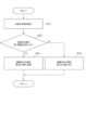
- 2 is a flowchart illustrating a control operation of the vehicle illustrated in FIG. 1 .
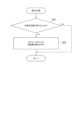
- 2 is a flowchart illustrating a control operation of the vehicle illustrated in FIG. 1 .
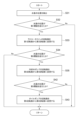
- 10 is a flowchart showing an operation of a vehicle according to a second embodiment.
- FIG. 4 is a diagram illustrating an example of a first threshold, a second threshold, and a third threshold.
- Fig. 1 is a schematic diagram showing a mechanical configuration of a vehicle 1A according to the first embodiment.
- the vehicle 1A according to the first embodiment includes an internal combustion engine 2 and an auxiliary device 3 for cooling the internal combustion engine 2.
- the internal combustion engine 2 is, for example, a gasoline engine or a diesel engine, but is not limited thereto.
- the auxiliary device 3 for cooling the internal combustion engine 2 is, for example, a radiator fan 32, a cooling water pump 33, and an oil pump 34, but is not limited thereto.
- the internal combustion engine 2 is provided with a cooling water circuit 4, which is a passage for circulating cooling water through the internal combustion engine 2.
- the cooling water circuit 4 is provided with a radiator 31 and a cooling water pump 33.
- the radiator 31 is a device for dissipating heat from the cooling water heated by the internal combustion engine 2, and is installed, for example, in front of the internal combustion engine 2.
- the cooling water pump 33 is a device for circulating the cooling water filled in the cooling water circuit 4.
- the cooling water pump 33 may be a mechanical pump that is powered by power transmitted from the internal combustion engine 2, or an electric pump that is powered by electricity supplied from a battery.
- the output value can be changed, for example, by providing an electromagnetic clutch between the internal combustion engine 2 and the mechanical pump, and with an electric pump, the output value can be changed, for example, by changing the pulse width (duty ratio).
- the radiator fan 32 is a device for promoting heat dissipation from the cooling water in the radiator 31, and is installed, for example, behind the radiator 31.
- the radiator fan 32 includes a mechanical fan that is powered by power transmitted from the internal combustion engine 2, and an electric fan that is powered by electricity supplied from a battery.
- the output value can be changed, for example, by providing an electromagnetic clutch (not shown) between the internal combustion engine 2 and the mechanical fan, and with an electric fan, the output value can be changed, for example, by changing the pulse width (duty ratio).
- the oil pump 34 is a device that ensures lubrication and cooling of various parts of the internal combustion engine 2 by supplying oil to each part.
- the oil pump 34 is either a mechanical pump that runs on power transmitted from the internal combustion engine 2, or an electric pump that runs on electricity supplied from a battery.
- the output value can be changed, for example, by providing an electromagnetic clutch between the internal combustion engine 2 and the mechanical pump, and with an electric pump, the output value can be changed, for example, by changing the pulse width (duty ratio).
- FIG. 2 is a block diagram showing a schematic control configuration of the vehicle 1A shown in Fig. 1.
- the vehicle 1A according to the first embodiment includes a detection device 5 that detects the height of the water surface around the vehicle 1A, and a control device 6A that changes the output value of the auxiliary device 3.
- the detection device 5 is, for example, a level sensor such as a float switch or a distance sensor such as a radar, but is not limited to these.
- the height of the water surface around the vehicle 1A represents the relative position of the water surface to the vehicle 1A submerged in water, i.e., the relative position of the water surface to the internal combustion engine 2 mounted on the vehicle 1A.
- the control device 6A is provided, for example, in an internal combustion engine control device (hereinafter referred to as "engine ECU") that controls the internal combustion engine 2 and the auxiliary equipment 3, but is not limited to this and may be provided separately from the engine ECU.
- the control device 6A is, for example, configured with a processor consisting of an arithmetic unit, registers that store instructions and information, and peripheral circuits, memories such as ROM (Read Only Memory) and RAM (Random Access Memory), and an input interface, but is not limited to this.
- the control device 6A changes the output of the auxiliary device 3 to a second output value smaller than the first output value up to the first threshold value LV1.
- the first threshold value LV1 is, for example, the position where the internal combustion engine 2 is submerged in water, i.e., the height of the lower end of the internal combustion engine 2, and is determined by correlating the vertical position of the vehicle 1A with the vertical position of the internal combustion engine 2.
- the first output value up to the first threshold value LV1 is, for example, a variable value that varies with the rotation speed of the internal combustion engine 2 or a variable value that varies with the temperature of the cooling water, but may also be a fixed value that does not vary.
- the second output value after the second output value becomes higher than the first threshold value LV1 may be a variable value that varies with the rotation speed of the internal combustion engine 2 or the temperature of the cooling water, or may be a fixed value that does not vary, as long as it is smaller than the first output value.
- the first output value and the second output value are variable values that vary depending on the rotation speed of the internal combustion engine 2
- the second output value is smaller than the first output value when compared under conditions where the rotation speed of the internal combustion engine 2 is the same.
- FIG. 3 is a flowchart showing the operation of the vehicle 1A shown in FIG. 1.
- the detection device 5 detects the height of the water surface (step S11).
- the output value of the auxiliary device 3 is set to the first output value (step S13).
- step S12: Yes when the height of the water surface is higher than the first threshold value LV1 (step S12: Yes), the output value of the auxiliary device 3 is changed to a second output value smaller than the first output value (step S14).
- the auxiliary device 3 is the radiator fan 32
- the first output value and the second output value are the rotation speed of the radiator fan 32 per unit time (hereinafter, simply referred to as "rotation speed"). That is, when the water surface height is higher than the first threshold value LV1 (step S12: Yes), the rotation speed of the radiator fan 32 is made smaller than when the water surface height is lower than the first threshold value LV1.
- step S21: Yes If the water surface height is higher than the first threshold value LV1, i.e., if step S12 in FIG. 3 is Yes, and the water surface height becomes higher than the previous height (step S21: Yes), the rotation speed of the radiator fan 32 is reduced from the previous rotation speed. If the water surface height does not change (step S21: No), the rotation speed of the radiator fan 32 is maintained. Note that if the water surface height becomes lower than the previous height, the rotation speed of the radiator fan 32 may be reduced from the previous speed. The rotation speed of the radiator fan 32 may be gradually or stepwise reduced in response to the water surface height.
- the rotation speed of the radiator fan 32 is reduced as the water surface height increases. This allows the energy for operating the auxiliary device 3 to be saved more effectively.
- the first threshold value LV1 is set to the water surface height at which the internal combustion engine 2 is submerged, but this is not limiting, and may be set to, for example, the water surface height at which the radiator fan 32 is submerged, or the water surface height at which the radiator 31 is submerged. Furthermore, the first threshold value LV1 may be set to a water surface height at which the internal combustion engine 2 is not submerged, as long as the water surface height is high enough to sufficiently cool the internal combustion engine 2 by waves and splashes generated in the surrounding water as the vehicle 1A travels. The water surface height at which the internal combustion engine 2 is sufficiently cooled by waves and splashes may be set in advance based on experiments or analysis. In other words, the first threshold value LV1 may be set to a water surface height at which the cooling of the internal combustion engine 2 and the cooling water flowing to the internal combustion engine 2 is promoted by the water around the vehicle 1A.
- the mechanical configuration of the vehicle 1B of embodiment 2 is the same as the mechanical configuration of the vehicle 1A of embodiment 1, but the auxiliary equipment 3 of the vehicle 1B of embodiment 2 includes a radiator fan 32, a cooling water pump 33, and an oil pump 34.
- the control configuration of the vehicle 1B according to the second embodiment is the same as the control configuration of the vehicle 1A according to the first embodiment, except for the control device 6B.
- a second threshold value LV2 that is preset higher than the first threshold value LV1 and a third threshold value LV3 that is preset higher than the second threshold value LV2 are stored.
- the rotation speed of the radiator fan 32 is changed from the first rotation speed (first output value) to the second rotation speed (second output value).
- rotation speed the rotation speed per unit time of the cooling water pump 33 (hereinafter simply referred to as "rotation speed") is changed to a fourth rotation speed that is lower than the third rotation speed until the water level becomes higher than the second threshold value LV2.
- the rotation speed per unit time of the oil pump 34 (hereinafter simply referred to as "rotation speed") is changed to a sixth rotation speed that is lower than the fifth rotation speed until the water level becomes higher than the third threshold value LV3.
- the first rotation speed, the second rotation speed, the third rotation speed, the fourth rotation speed, the fifth rotation speed, and the sixth rotation speed may be variable values that vary depending on the rotation speed of the internal combustion engine 2 and the temperature of the cooling water, or may be fixed values that do not vary depending on the rotation speed of the internal combustion engine 2 and the temperature of the cooling water.
- the second rotation speed is smaller than the first rotation speed
- the fourth rotation speed is smaller than the third rotation speed
- the sixth rotation speed is smaller than the fifth rotation speed, when compared under the same rotation speed of the internal combustion engine 2.
- [Vehicle Operation] 5 is a flowchart showing the operation of the vehicle 1B according to the second embodiment.
- the detection device 5 detects the height of the water surface (step S31).
- the rotation speed of the radiator fan 32 is changed to a second rotation speed that is lower than the first rotation speed until the water surface becomes higher than the first threshold value LV1 (step S33).
- step S34 When the height of the water surface becomes higher and higher than the second threshold value LV2 (step S34: Yes), the rotation speed of the cooling water pump 33 is changed to a fourth rotation speed that is lower than the third rotation speed until the water surface becomes higher than the second threshold value LV2 (step S35).
- step S42 When the height of the water surface becomes higher and higher than the third threshold value LV3 (step S42: Yes), the rotation speed of the oil pump 34 is changed to a sixth rotation speed that is lower than the fifth rotation speed until the water surface becomes higher than the third threshold value LV3 (step S43). That is, as the water level increases, the rotation speeds of the radiator fan 32, the cooling water pump 33, and the oil pump 34 are reduced in that order.
- the first threshold value LV1, the second threshold value LV2, and the third threshold value LV3 are set to values as shown in FIG. 6.
- the first threshold value LV1 is set at the lower end position in the height direction of the internal combustion engine 2
- the second threshold value LV2 is set at the middle position in the height direction of the internal combustion engine 2
- the third threshold value LV3 is set at the upper end position in the height direction of the internal combustion engine 2.
- the rotation speed of the radiator fan 32 is changed from the first rotation speed to the second rotation speed which is lower than the first rotation speed, so that the energy for moving the radiator fan 32 can be saved.
- the rotation speed of the radiator fan 32 which is the auxiliary device 3 whose driving energy changes according to the water level, energy saving starts before the water level rises further and the energy for moving the radiator fan 32 increases.
- the rotation speed of the cooling water pump 33 is further changed from the third rotation speed to the fourth rotation speed which is lower than the third rotation speed, so that the energy for moving the cooling water pump 33 can be saved.
- the radiator 31 is also submerged in water. Therefore, since it is considered that the cooling capacity of the cooling water by the radiator 31 is improved, even if the rotation speed of the cooling water pump 33 is reduced, the cooling capacity of the internal combustion engine 2 can be sufficiently secured.
- the rotation speed of the oil pump 34 is further changed from the fifth rotation speed to a sixth rotation speed which is lower than the fifth rotation speed, and energy for operating the oil pump 34 can be saved.
- the rotation speed of the oil pump 34 When the rotation speed of the oil pump 34 is reduced, the amount of lubricating oil supplied to the internal combustion engine 2 is reduced, and the friction is increased, which is considered to deteriorate fuel efficiency.
- the internal combustion engine 2 When the internal combustion engine 2 is submerged in water up to the top end in the height direction, the internal combustion engine 2 is sufficiently cooled by the surrounding water, and the viscosity of the lubricating oil is also considered to be sufficiently secured. Therefore, even if the rotation speed of the oil pump 34 is reduced, it is considered that the increase in friction is not large, so that priority is given to saving energy for operating the oil pump 34.
- the first threshold value LV1, the second threshold value LV2, and the third threshold value LV3 are not limited to those described above.
- the present invention is not limited to the above-described embodiments, but includes variations on the above-described embodiments and appropriate combinations of these embodiments.
Landscapes
- Engineering & Computer Science (AREA)
- Chemical & Material Sciences (AREA)
- Combustion & Propulsion (AREA)
- Mechanical Engineering (AREA)
- General Engineering & Computer Science (AREA)
- Combined Controls Of Internal Combustion Engines (AREA)
Abstract
車両は、内燃機関と、前記内燃機関を冷却するための補機と、を備えた車両であって、前記車両の周囲の水面の高さを検出する検出装置と、前記水面の高さが予め定められた第1閾値よりも高くなった場合に、前記補機の出力値を、前記第1閾値よりも高くなるまでの第1出力値よりも小さな第2出力値に変更する制御装置と、を備える。
Description
本開示は、車両に関する。
内燃機関と、内燃機関を冷却するための補機と、を備えた車両が広く知られている。内燃機関を冷却するための補機には、例えば、ラジエータファン(特許文献1参照)、及び冷却水ポンプ(特許文献2参照)がある。
ところで、車両が水に浸かることで、内燃機関が水に浸かると、内燃機関の冷却が進むので、内燃機関を冷却するための補機の出力値を、内燃機関が水に浸かる前よりも小さくすることができる。それにより、内燃機関を冷却するための補機の出力値を、内燃機関が水に浸かる前よりも小さくすると、補機を動かすためのエネルギの節約が可能となる。
上述の事情に鑑みて、本発明の少なくとも一実施形態は、補機を動かすためのエネルギを節約することができる車両を提供することを目的とする。
(1)本発明の少なくとも一実施形態に係る車両は、内燃機関と、前記内燃機関を冷却するための補機と、を備えた車両であって、前記車両の周囲の水面の高さを検出する検出装置と、前記水面の高さが予め定められた第1閾値よりも高くなった場合に、前記補機の出力値を、前記第1閾値よりも高くなるまでの第1出力値よりも小さな第2出力値に変更する制御装置と、を備える。
上記(1)の構成によれば、車両の周囲の水面の高さが第1閾値よりも高くなったとき、内燃機関が車両周囲の水によって冷却される可能性が高いと判断し、補機の出力値が第1出力値から第1出力値よりも小さな第2出力値に変更される。これにより、補機を動かすためのエネルギを節約することができる。
(2)幾つかの実施形態では、上記(1)の構成において、前記補機には、ラジエータファンが含まれ、前記制御装置は、前記水面の高さが前記第1閾値よりも高くなった場合に、前記水面の高さが高くなるにしたがって、前記ラジエータファンの回転数を減少させる。
上記(2)の構成によれば、水面が高くなるほどラジエータファンの回転数が減少する。水面が高くなるほどラジエータファンが車両周囲の水に浸かり、ラジエータファンの駆動抵抗が増加する可能性が高いが、水面の位置が高くなるほどラジエータファンの回転数を減少させることで、ラジエータファンを動かすためのエネルギを節約することができる。
(3)幾つかの実施形態では、上記(1)の構成において、前記補機には、ラジエータファンと冷却水ポンプとが含まれ、前記制御装置は、前記水面の高さが前記第1閾値よりも高くなった場合に、前記ラジエータファンの回転数を、前記第1閾値よりも高くなるまでの第1回転数よりも少ない第2回転数に変更し、前記水面の高さが前記第1閾値よりも予め高く定められた第2閾値よりも高くなる場合に、前記冷却水ポンプの回転数を、第2閾値よりも高くなるまでの第3回転数よりも少ない第4回転数に変更する。
上記(3)の構成によれば、水面の高さが第1閾値よりも高くなったとき、水面の高さが駆動抵抗に影響するラジエータファンの回転数を冷却水ポンプより先に低下させ、水面の高さが第1閾値よりも高い第2閾値よりも高くなったとき、さらに、冷却水ポンプの回転数も低下される。これにより、ラジエータファンを動かすためのエネルギと冷却水ポンプを動かすためのエネルギをより効果的に節約することができる。
(4)幾つかの実施形態では、上記(3)の構成において、前記補機には、オイルポンプが含まれ、前記制御装置は、前記水面の高さが前記第2閾値よりも予め高く定められた第3閾値よりも高くなる場合に、前記オイルポンプの回転数を、前記第3閾値よりも高くなるまでの第5回転数よりも少ない第6回転数に変更する。
上記(4)の構成によれば、水面の高さが第2閾値よりも高い第3閾値よりも高くなったとき、オイルポンプの回転数が低下される。すなわち、内燃機関の燃費に影響を与えるオイルポンプの回転数の低下を、ラジエータファンや冷却水ポンプの回転数の低下よりも後回しにする。これにより、ラジエータファンや冷却水ポンプを動かすためのエネルギをより効果的に節約するとともに、オイルポンプを動かすためのエネルギをより効果的に節約することができ、内燃機関の燃費の悪化を抑制することができる。
本発明の少なくとも一実施形態によれば、補機を動かすためのエネルギを節約することができる。
以下、添付図面を参照して本発明の実施形態について説明する。ただし、実施形態として記載されている又は図面に示されている構成部品の寸法、材質、形状、その相対的配置等は、本発明の範囲をこれに限定する趣旨ではなく、単なる説明例にすぎない。
[実施形態1]
[車両の機械構成]
図1は、実施形態1に係る車両1Aの機械構成を概略的に示す構成図である。図1に示すように、実施形態1に係る車両1Aは、内燃機関2と、内燃機関2を冷却するための補機3と、を備えている。内燃機関2は、例えば、ガソリンエンジン、又はディーゼルエンジンであるが、これに限られるものではない。内燃機関2を冷却するための補機3は、例えば、ラジエータファン32、冷却水ポンプ33、及びオイルポンプ34であるが、これに限られるものではない。
[車両の機械構成]
図1は、実施形態1に係る車両1Aの機械構成を概略的に示す構成図である。図1に示すように、実施形態1に係る車両1Aは、内燃機関2と、内燃機関2を冷却するための補機3と、を備えている。内燃機関2は、例えば、ガソリンエンジン、又はディーゼルエンジンであるが、これに限られるものではない。内燃機関2を冷却するための補機3は、例えば、ラジエータファン32、冷却水ポンプ33、及びオイルポンプ34であるが、これに限られるものではない。
内燃機関2には、内燃機関2に冷却水を循環させる通路である冷却水回路4が設けられる。冷却水回路4には、ラジエータ31及び冷却水ポンプ33が設けられる。ラジエータ31は、内燃機関2で加熱された冷却水の熱を放熱するための装置であり、例えば、内燃機関2の前方に設置される。
冷却水ポンプ33は、冷却水回路4に充填された冷却水を循環するため装置である。冷却水ポンプ33には、内燃機関2から伝達された動力によって動く機械式のポンプ、及びバッテリから供給された電力によって動く電動式のポンプがある。機械式のポンプでは、例えば、内燃機関2と機械式のポンプとの間に電磁クラッチを設けることで出力値を変更することができ、電動式のポンプでは、例えば、パルス幅(duty比)を変更することで出力値を変更することができる。
ラジエータファン32は、ラジエータ31における冷却水の放熱を促進するための装置であり、例えば、ラジエータ31の後方に設置される。ラジエータファン32には、内燃機関2から伝達された動力によって動く機械式のファン、及びバッテリから供給された電力によって動く電動式のファンがある。機械式のファンでは、例えば、内燃機関2と機械式のファンとの間に電磁クラッチ(図示せず)を設けることで出力値を変更することができ、電動式のファンでは、例えば、パルス幅(duty比)を変更することで出力値を変更することができる。
オイルポンプ34は、内燃機関2の各所にオイルを供給することで、各所の潤滑と各所の冷却を確保する装置である。オイルポンプ34には、内燃機関2から伝達された動力によって動く機械式のポンプ、及びバッテリから供給された電力によって動く電動式のポンプがある。機械式のポンプでは、例えば、内燃機関2と機械式ポンプとの間に電磁クラッチを設けることで出力値を変更することができ、電動式のポンプでは、例えば、パルス幅(duty比)を変更することで出力値を変更することができる。
[車両の制御構成]
図2は、図1に示した車両1Aの制御構成を概略的に示すブロック図である。図2に示すように、実施形態1に係る車両1Aは、車両1Aの周囲の水面の高さを検出する検出装置5と、補機3の出力値を変更する制御装置6Aと、を備えている。
図2は、図1に示した車両1Aの制御構成を概略的に示すブロック図である。図2に示すように、実施形態1に係る車両1Aは、車両1Aの周囲の水面の高さを検出する検出装置5と、補機3の出力値を変更する制御装置6Aと、を備えている。
検出装置5は、例えば、フロートスイッチ等のレベルセンサ又はレーダ等の距離センサであるが、これに限られるものではない。なお、車両1Aの周囲の水面の高さは、水に浸かった車両1Aに対する水面の相対的位置、すなわち、車両1Aに搭載されている内燃機関2に対する水面の相対的位置を表している。
制御装置6Aは、例えば、内燃機関2及び補機3を制御する内燃機関制御装置(以下「エンジンECU」という)に設けられるが、これに限られるものではなく、エンジンECUとは別に設けてもよい。制御装置6Aは、例えば、演算装置、命令や情報を格納するレジスタ、及び周辺回路等から構成されるプロセッサ、ROM(Read Only Memory)、RAM(Random Acess Memory)等のメモリ、及び入力インタフェースによって構成されるが、これに限られるものではない。
制御装置6Aは、車両1Aの周囲の水面の高さが予め定められた第1閾値LV1よりも高くなった場合、補機3の出力を、第1閾値LV1を超えるまでの第1出力値よりも小さな第2出力値に変更する。第1閾値LV1は、例えば、内燃機関2が水に浸かる位置、すなわち内燃機関2の下端の高さであり、車両1Aの高さ方向の位置と内燃機関2の高さ方向の位置を関連付けることにより定められる。第1閾値LV1よりも高くなるまでの第1出力値は、例えば、内燃機関2の回転数によって変動する変動値、又は冷却水の温度によって変動する変動値であるが、変動しない固定値であってもよい。第1閾値LV1よりも高くなった後の第2出力値は、第1出力値よりも小さいものであれば、内燃機関2の回転数又は冷却水の温度で変動する変動値であってもよいし、変動しない固定値であってもよい。なお、第1出力値および第2出力値が内燃機関2の回転数によって変動する変動値である場合は、内燃機関2の回転数が同じ状態で比較して、第2出力値は第1出力値よりも小さいものである。
[車両の動作]
実施形態1における車両1Aの動作について、詳細を説明する。実施形態1に係る車両1Aの補機3には、ラジエータファン32が含まれる。図3は、図1に示した車両1Aの動作を示すフローチャートである。図3に示すように、実施形態1に係る車両1Aでは、検出装置5が水面の高さを検出する(ステップS11)。水面の高さ第1閾値LV1より低い場合(ステップS12:No)に、補機3の出力値を、第1出力値とする(ステップS13)。一方、水面の高さが第1閾値LV1より高い場合(ステップS12:Yes)に、補機3の出力値を、第1出力値よりも小さな第2出力値に変更する(ステップS14)。補機3がラジエータファン32である場合、第1出力値および第2出力値はラジエータファン32の単位時間当たりの回転数(以下、単に「回転数」と記載する)である。すなわち、水面の高さが第1閾値LV1より高い場合(ステップS12:Yes)は、ラジエータファン32の回転数を、水面の高さが第1閾値LV1より低い場合に比べ小さくする。
実施形態1における車両1Aの動作について、詳細を説明する。実施形態1に係る車両1Aの補機3には、ラジエータファン32が含まれる。図3は、図1に示した車両1Aの動作を示すフローチャートである。図3に示すように、実施形態1に係る車両1Aでは、検出装置5が水面の高さを検出する(ステップS11)。水面の高さ第1閾値LV1より低い場合(ステップS12:No)に、補機3の出力値を、第1出力値とする(ステップS13)。一方、水面の高さが第1閾値LV1より高い場合(ステップS12:Yes)に、補機3の出力値を、第1出力値よりも小さな第2出力値に変更する(ステップS14)。補機3がラジエータファン32である場合、第1出力値および第2出力値はラジエータファン32の単位時間当たりの回転数(以下、単に「回転数」と記載する)である。すなわち、水面の高さが第1閾値LV1より高い場合(ステップS12:Yes)は、ラジエータファン32の回転数を、水面の高さが第1閾値LV1より低い場合に比べ小さくする。
次に図4について説明する。水面の高さが第1閾値LV1より高い場合、すなわち図3のステップS12がYesの場合、水面の高さが直前の高さよりも高くなると(ステップS21:Yes)、ラジエータファン32の回転数を直前の回転数より減少させる。水面の高さが変わらない場合(ステップS21:No)は、ラジエータファン32の回転数を維持する。なお、水面の高さが直前より低くなる場合は、ラジエータファン32の回転数を直前より低下させてもよい。ラジエータファン32の回転数は、水面の高さに対応するように漸次減少させてもよいし、段階的に減少させてもよい。
[効果]
内燃機関2が水に浸かると、内燃機関2の冷却が促進されるので、補機3の出力を低下させても内燃機関2を冷却することができる。実施形態1では、内燃機関2が水に浸かると、補機3の出力値が第1出力値から第1出力値よりも小さな第2出力値に変更される。これにより、補機3を動かすためのエネルギを節約することができる。特に、補機3がラジエータファン32である場合、ラジエータファン32が水に浸かるとラジエータファン32の駆動抵抗が上昇するので、ラジエータファン32が水に浸かる前に比べ、同回転数を維持しようとするためのラジエータファン32の駆動エネルギが増大する。さらに、ラジエータファン32がより多く水に浸かるほど、同回転数を維持しようとするためのラジエータファン32の駆動エネルギが増大する。そこで、実施形態1では、水面の高さが高くなるほどラジエータファン32の回転数を低下させる。これにより、補機3を動かすためのエネルギをより効果的に節約することができる。
内燃機関2が水に浸かると、内燃機関2の冷却が促進されるので、補機3の出力を低下させても内燃機関2を冷却することができる。実施形態1では、内燃機関2が水に浸かると、補機3の出力値が第1出力値から第1出力値よりも小さな第2出力値に変更される。これにより、補機3を動かすためのエネルギを節約することができる。特に、補機3がラジエータファン32である場合、ラジエータファン32が水に浸かるとラジエータファン32の駆動抵抗が上昇するので、ラジエータファン32が水に浸かる前に比べ、同回転数を維持しようとするためのラジエータファン32の駆動エネルギが増大する。さらに、ラジエータファン32がより多く水に浸かるほど、同回転数を維持しようとするためのラジエータファン32の駆動エネルギが増大する。そこで、実施形態1では、水面の高さが高くなるほどラジエータファン32の回転数を低下させる。これにより、補機3を動かすためのエネルギをより効果的に節約することができる。
なお、実施形態1では、第1閾値LV1を内燃機関2が水に浸かる水面の高さとしたが、これに限らず、例えばラジエータファン32が水に浸かる水面の高さ、またはラジエータ31が水に浸かる水面の高さとしてもよい。また、第1閾値LV1は、内燃機関2が水に浸からない程度の水面の高さであっても、車両1Aの走行によって周囲の水に発生する波や水しぶきによって、内燃機関2が十分に冷却される程度の水面の高さであればよい。波や水しぶきによって内燃機関2が十分に冷却される程度の水面の高さは、実験や解析に基づいて予め設定すればよい。すなわち、第1閾値LV1は、車両1Aの周囲の水によって、内燃機関2や、内燃機関2に流れる冷却水の冷却が促進される程度の水面の高さに設定されていればよい。
[実施形態2]
[車両の機械構成]
実施形態2に係る車両1Bの機械構成は、実施形態1に係る車両1Aの機械構成と同じであるが、実施形態2に係る車両1Bの補機3には、ラジエータファン32と冷却水ポンプ33、及びオイルポンプ34とが含まれる。
[車両の機械構成]
実施形態2に係る車両1Bの機械構成は、実施形態1に係る車両1Aの機械構成と同じであるが、実施形態2に係る車両1Bの補機3には、ラジエータファン32と冷却水ポンプ33、及びオイルポンプ34とが含まれる。
[車両の制御構成]
実施形態2に係る車両1Bの制御構成は、制御装置6Bを除いて、実施形態1に係る車両1Aの制御構成と同じである。
実施形態2に係る車両1Bの制御構成は、制御装置6Bを除いて、実施形態1に係る車両1Aの制御構成と同じである。
実施形態2に係る車両1Bの制御装置6Bは、第1閾値LV1に加え、第1閾値LV1よりも予め高く定められた第2閾値LV2、第2閾値LV2よりも予め高く定められた第3閾値LV3が記憶される。そして、水面の高さが第1閾値LV1よりも高くなった場合に、ラジエータファン32の回転数を、第1回転数(第1出力値)から第2回転数(第2出力値)に変更し、水面の高さが第2閾値LV2よりも高くなった場合に、冷却水ポンプ33の単位時間当たりの回転数(以下、単に「回転数」と記載する)を、第2閾値LV2よりも高くなるまでの第3回転数よりも少ない第4回転数に変更する。そして、水面の高さが第3閾値LV3よりも高くなった場合に、オイルポンプ34の単位時間当たりの回転数(以下、単に「回転数」と記載する)を、第3閾値LV3より高くなるまでの第5回転数よりも少ない第6回転数に変更する。第1回転数、第2回転数、第3回転数、第4回転数、第5回転数、及び第6回転数は、内燃機関2の回転数や冷却水の温度によって変動する変動値であってもよいが、内燃機関2の回転数や冷却水の温度によって変動しない固定値であってもよい。なお、第1回転数、第2回転数、第3回転数、第4回転数、第5回転数、及び第6回転数が内燃機関2の回転数によって変動する変動値である場合は、内燃機関2の回転数が同じ状態で比較して、第2回転数は第1回転数よりも小さいもの、第4回転数は第3回転数よりも小さいもの、第6回転数は第5回転数よりも小さいものである。
[車両の動作]
図5は、実施形態2に係る車両1Bの動作を示すフローチャートである。図5に示すように、実施形態2に係る車両1Bでは、検出装置5が水面の高さを検出する(ステップS31)。水面の高さが第1閾値LV1よりも高くなった場合(ステップS32:Yes)に、ラジエータファン32の回転数を、第1閾値LV1よりも高くなるまでの第1回転数よりも少ない第2回転数に変更する(ステップS33)。そして、水面の高さが高くなり、第2閾値LV2よりも高くなった場合(ステップS34:Yes)に、冷却水ポンプ33の回転数を、第2閾値LV2よりも高くなるまでの第3回転数よりも少ない第4回転数に変更する(ステップS35)。そして、水面の高さが更に高くなり、第3閾値LV3よりも高くなった場合(ステップS42:Yes)に、オイルポンプ34の回転数を、第3閾値LV3よりも高くなるまでの第5回転数よりも少ない第6回転数に変更する(ステップS43)。すなわち、水面の高さが高くなるにしたがって、ラジエータファン32、冷却水ポンプ33、オイルポンプ34の順で回転数を低下させていく。
図5は、実施形態2に係る車両1Bの動作を示すフローチャートである。図5に示すように、実施形態2に係る車両1Bでは、検出装置5が水面の高さを検出する(ステップS31)。水面の高さが第1閾値LV1よりも高くなった場合(ステップS32:Yes)に、ラジエータファン32の回転数を、第1閾値LV1よりも高くなるまでの第1回転数よりも少ない第2回転数に変更する(ステップS33)。そして、水面の高さが高くなり、第2閾値LV2よりも高くなった場合(ステップS34:Yes)に、冷却水ポンプ33の回転数を、第2閾値LV2よりも高くなるまでの第3回転数よりも少ない第4回転数に変更する(ステップS35)。そして、水面の高さが更に高くなり、第3閾値LV3よりも高くなった場合(ステップS42:Yes)に、オイルポンプ34の回転数を、第3閾値LV3よりも高くなるまでの第5回転数よりも少ない第6回転数に変更する(ステップS43)。すなわち、水面の高さが高くなるにしたがって、ラジエータファン32、冷却水ポンプ33、オイルポンプ34の順で回転数を低下させていく。
[効果]
水面が高くなるほど内燃機関2の冷却が促進されるので、内燃機関2を冷却する複数の補機3において、水面が高くなるほど出力(回転数)を低下させる補機3の種類を増加させる。このとき、水面の高さに応じて駆動エネルギが変化する補機3であるラジエータファン32の回転数を優先的に低下させ、内燃機関2の潤滑、すなわち燃費に影響するオイルポンプ34の回転数は極力低下させないようにする。これにより、補機3のエネルギを節約するとともに、内燃機関2の燃費の悪化を抑制することができる。実施形態2では、第1閾値LV1、第2閾値LV2、及び第3閾値LV3を、図6に示すような値に設定している。図6に示すように、第1閾値LV1は内燃機関2の高さ方向下端の位置、第2閾値LV2は内燃機関2の高さ方向中程の位置、第3閾値LV3は内燃機関2の高さ方向上端の位置に設定されている。水面の高さが第1閾値LV1に達し内燃機関2の高さ方向下端まで水に浸かると、冷却水のみではなく周囲の水によっても内燃機関2が冷却される。そこで、ラジエータファン32の回転数が、第1回転数から第1回転数よりも少ない第2回転数に変更され、ラジエータファン32を動かすためのエネルギを節約することができる。水面の高さに応じて駆動エネルギが変化する補機3であるラジエータファン32の回転数を低下させることで、水面の高さが更に上昇しラジエータファン32を動かすためのエネルギが増大する前に、エネルギの節約を開始する。水面の高さが第2閾値LV2に達し内燃機関2の高さ方向中程まで水に浸かると、さらに、冷却水ポンプ33の回転数が、第3回転数から第3回転数よりも少ない第4回転数に変更され、冷却水ポンプ33を動かすためのエネルギを節約することができる。内燃機関2の高さ方向中程まで水に浸かると、ラジエータ31も水に浸かっていると考えられる。したがって、ラジエータ31による冷却水の冷却能力が向上していると考えられるので、冷却水ポンプ33の回転数を低下させても十分に内燃機関2の冷却能力を確保できる。水面の高さが第3閾値LV3に達し内燃機関2の高さ方向上端まで水に浸かると、さらに、オイルポンプ34の回転数が、第5回転数から第5回転数よりも少ない第6回転数に変更され、オイルポンプ34を動かすためのエネルギを節約することができる。オイルポンプ34の回転数を低下させると、内燃機関2に供給される潤滑油の量が低下し、フリクションが増加することで燃費が悪化することが考えられる。内燃機関2の高さ方向上端まで水に浸かっていると、周囲の水によって内燃機関2が十分に冷却され、潤滑油の粘性も十分に確保できると考えられる。よって、オイルポンプ34の回転数を低下させても、フリクションの増加が大きくないと考えられるため、オイルポンプ34を動かすためのエネルギを節約することを優先させる。なお、第1閾値LV1、第2閾値LV2、及び第3閾値LV3は、上記のものに限らない。
水面が高くなるほど内燃機関2の冷却が促進されるので、内燃機関2を冷却する複数の補機3において、水面が高くなるほど出力(回転数)を低下させる補機3の種類を増加させる。このとき、水面の高さに応じて駆動エネルギが変化する補機3であるラジエータファン32の回転数を優先的に低下させ、内燃機関2の潤滑、すなわち燃費に影響するオイルポンプ34の回転数は極力低下させないようにする。これにより、補機3のエネルギを節約するとともに、内燃機関2の燃費の悪化を抑制することができる。実施形態2では、第1閾値LV1、第2閾値LV2、及び第3閾値LV3を、図6に示すような値に設定している。図6に示すように、第1閾値LV1は内燃機関2の高さ方向下端の位置、第2閾値LV2は内燃機関2の高さ方向中程の位置、第3閾値LV3は内燃機関2の高さ方向上端の位置に設定されている。水面の高さが第1閾値LV1に達し内燃機関2の高さ方向下端まで水に浸かると、冷却水のみではなく周囲の水によっても内燃機関2が冷却される。そこで、ラジエータファン32の回転数が、第1回転数から第1回転数よりも少ない第2回転数に変更され、ラジエータファン32を動かすためのエネルギを節約することができる。水面の高さに応じて駆動エネルギが変化する補機3であるラジエータファン32の回転数を低下させることで、水面の高さが更に上昇しラジエータファン32を動かすためのエネルギが増大する前に、エネルギの節約を開始する。水面の高さが第2閾値LV2に達し内燃機関2の高さ方向中程まで水に浸かると、さらに、冷却水ポンプ33の回転数が、第3回転数から第3回転数よりも少ない第4回転数に変更され、冷却水ポンプ33を動かすためのエネルギを節約することができる。内燃機関2の高さ方向中程まで水に浸かると、ラジエータ31も水に浸かっていると考えられる。したがって、ラジエータ31による冷却水の冷却能力が向上していると考えられるので、冷却水ポンプ33の回転数を低下させても十分に内燃機関2の冷却能力を確保できる。水面の高さが第3閾値LV3に達し内燃機関2の高さ方向上端まで水に浸かると、さらに、オイルポンプ34の回転数が、第5回転数から第5回転数よりも少ない第6回転数に変更され、オイルポンプ34を動かすためのエネルギを節約することができる。オイルポンプ34の回転数を低下させると、内燃機関2に供給される潤滑油の量が低下し、フリクションが増加することで燃費が悪化することが考えられる。内燃機関2の高さ方向上端まで水に浸かっていると、周囲の水によって内燃機関2が十分に冷却され、潤滑油の粘性も十分に確保できると考えられる。よって、オイルポンプ34の回転数を低下させても、フリクションの増加が大きくないと考えられるため、オイルポンプ34を動かすためのエネルギを節約することを優先させる。なお、第1閾値LV1、第2閾値LV2、及び第3閾値LV3は、上記のものに限らない。
本発明は、上述した実施形態に限定されることはなく、上述した実施形態に変形を加えた形態や、これらの形態を適宜組み合わせた形態を含む。
1A,1B 車両
2 内燃機関
3 補機
31 ラジエータ
32 ラジエータファン
33 冷却水ポンプ
34 オイルポンプ
4 冷却水回路
5 検出装置
6A,6B 制御装置
LV1 第1閾値
LV2 第2閾値
LV3 第3閾値
2 内燃機関
3 補機
31 ラジエータ
32 ラジエータファン
33 冷却水ポンプ
34 オイルポンプ
4 冷却水回路
5 検出装置
6A,6B 制御装置
LV1 第1閾値
LV2 第2閾値
LV3 第3閾値
Claims (4)
- 内燃機関と、
前記内燃機関を冷却するための補機と、
を備えた車両であって、
前記車両の周囲の水面の高さを検出する検出装置と、
前記水面の高さが予め定められた第1閾値よりも高くなった場合に、前記補機の出力値を、前記第1閾値よりも高くなるまでの第1出力値よりも小さな第2出力値に変更する制御装置と、
を備えた車両。 - 前記補機には、ラジエータファンが含まれ、
前記制御装置は、前記水面の高さが前記第1閾値よりも高くなった場合に、前記水面の高さが高くなるにしたがって、前記ラジエータファンの回転数を減少させる、
請求項1に記載の車両。 - 前記補機には、ラジエータファンと冷却水ポンプとが含まれ、
前記制御装置は、前記水面の高さが前記第1閾値よりも高くなった場合に、前記ラジエータファンの回転数を、前記第1閾値よりも高くなるまでの第1回転数よりも少ない第2回転数に変更し、前記水面の高さが前記第1閾値よりも予め高く定められた第2閾値よりも高くなる場合に、前記冷却水ポンプの回転数を、第2閾値よりも高くなるまでの第3回転数よりも少ない第4回転数に変更する、
請求項1に記載の車両。 - 前記補機には、オイルポンプが含まれ、
前記制御装置は、前記水面の高さが前記第2閾値よりも予め高く定められた第3閾値よりも高くなる場合に、前記オイルポンプの回転数を、前記第3閾値よりも高くなるまでの第5回転数よりも少ない第6回転数に変更する、
請求項3に記載の車両。
Priority Applications (2)
| Application Number | Priority Date | Filing Date | Title |
|---|---|---|---|
| JP2025529142A JPWO2025004290A1 (ja) | 2023-06-29 | 2023-06-29 | |
| PCT/JP2023/024278 WO2025004290A1 (ja) | 2023-06-29 | 2023-06-29 | 車両 |
Applications Claiming Priority (1)
| Application Number | Priority Date | Filing Date | Title |
|---|---|---|---|
| PCT/JP2023/024278 WO2025004290A1 (ja) | 2023-06-29 | 2023-06-29 | 車両 |
Publications (1)
| Publication Number | Publication Date |
|---|---|
| WO2025004290A1 true WO2025004290A1 (ja) | 2025-01-02 |
Family
ID=93938246
Family Applications (1)
| Application Number | Title | Priority Date | Filing Date |
|---|---|---|---|
| PCT/JP2023/024278 Ceased WO2025004290A1 (ja) | 2023-06-29 | 2023-06-29 | 車両 |
Country Status (2)
| Country | Link |
|---|---|
| JP (1) | JPWO2025004290A1 (ja) |
| WO (1) | WO2025004290A1 (ja) |
Citations (4)
| Publication number | Priority date | Publication date | Assignee | Title |
|---|---|---|---|---|
| JPS5920521A (ja) * | 1982-07-26 | 1984-02-02 | Isuzu Motors Ltd | 水冷式内燃機関の冷却系制御装置 |
| US20160311406A1 (en) * | 2013-12-06 | 2016-10-27 | Jaguar Land Rover Limited | Vehicle cooling system |
| JP2018114833A (ja) * | 2017-01-18 | 2018-07-26 | 日野自動車株式会社 | 電動車両用冷却装置 |
| CN112727590A (zh) * | 2021-01-12 | 2021-04-30 | 徐工集团工程机械股份有限公司 | 车辆及其控制方法 |
-
2023
- 2023-06-29 WO PCT/JP2023/024278 patent/WO2025004290A1/ja not_active Ceased
- 2023-06-29 JP JP2025529142A patent/JPWO2025004290A1/ja active Pending
Patent Citations (4)
| Publication number | Priority date | Publication date | Assignee | Title |
|---|---|---|---|---|
| JPS5920521A (ja) * | 1982-07-26 | 1984-02-02 | Isuzu Motors Ltd | 水冷式内燃機関の冷却系制御装置 |
| US20160311406A1 (en) * | 2013-12-06 | 2016-10-27 | Jaguar Land Rover Limited | Vehicle cooling system |
| JP2018114833A (ja) * | 2017-01-18 | 2018-07-26 | 日野自動車株式会社 | 電動車両用冷却装置 |
| CN112727590A (zh) * | 2021-01-12 | 2021-04-30 | 徐工集团工程机械股份有限公司 | 车辆及其控制方法 |
Also Published As
| Publication number | Publication date |
|---|---|
| JPWO2025004290A1 (ja) | 2025-01-02 |
Similar Documents
| Publication | Publication Date | Title |
|---|---|---|
| US7953520B2 (en) | Cooling fan controller for controlling revolving fan based on fluid temperature and air temperature | |
| JP6065397B2 (ja) | 電動モータ | |
| US20040103862A1 (en) | Engine temperature control apparatus and method | |
| US5564899A (en) | Engine cooling system with blade angle controllable cooling fan | |
| US6725812B1 (en) | Water pump driven by viscous coupling | |
| WO2025004290A1 (ja) | 車両 | |
| EP2037110A2 (en) | Engine protection system | |
| JP5699821B2 (ja) | 内燃機関の冷却装置 | |
| JP7003742B2 (ja) | 電動オイルポンプの流量制御装置 | |
| JP5027289B2 (ja) | エンジン冷却装置 | |
| CN114811005A (zh) | 车辆的冷却系统 | |
| JP2010060037A (ja) | 動力伝達装置の冷却構造 | |
| JP2013007306A (ja) | エンジンオイルの冷却装置 | |
| JP6065785B2 (ja) | 冷却水温度制御システム | |
| JP2020023882A (ja) | 車両用エンジン冷却装置 | |
| CN116006312A (zh) | 基于机油温度的发动机水温控制系统及方法 | |
| CN113650614B (zh) | 车辆控制方法、装置及车辆 | |
| JP2009057864A (ja) | 車両の制御装置、制御方法およびその方法をコンピュータで実現されるプログラムならびにそのプログラムを記録した記録媒体 | |
| CN120917249A (zh) | 用于影响电动车辆的至少一个变速器的温度的方法 | |
| JP2016079819A (ja) | エンジン冷却装置 | |
| JP2013199893A (ja) | 内燃機関の冷却ファン操作システム | |
| KR100231576B1 (ko) | 자동변속기 과열방지장치 | |
| KR19990003799A (ko) | 자동차용 엔진의 냉각수 펌프 제어 장치 | |
| JP2006336488A (ja) | 冷却ファン保護装置 | |
| JP2025144572A (ja) | 車両用冷却装置 |
Legal Events
| Date | Code | Title | Description |
|---|---|---|---|
| 121 | Ep: the epo has been informed by wipo that ep was designated in this application |
Ref document number: 23943682 Country of ref document: EP Kind code of ref document: A1 |
|
| ENP | Entry into the national phase |
Ref document number: 2025529142 Country of ref document: JP Kind code of ref document: A |
|
| WWE | Wipo information: entry into national phase |
Ref document number: 2025529142 Country of ref document: JP |
|
| NENP | Non-entry into the national phase |
Ref country code: DE |