WO2024257738A1 - 新規な熱電変換性溶融合成体及びその利用 - Google Patents
新規な熱電変換性溶融合成体及びその利用 Download PDFInfo
- Publication number
- WO2024257738A1 WO2024257738A1 PCT/JP2024/021103 JP2024021103W WO2024257738A1 WO 2024257738 A1 WO2024257738 A1 WO 2024257738A1 JP 2024021103 W JP2024021103 W JP 2024021103W WO 2024257738 A1 WO2024257738 A1 WO 2024257738A1
- Authority
- WO
- WIPO (PCT)
- Prior art keywords
- convertible
- thermoelectrically
- temperature
- thermoelectric conversion
- molten
- Prior art date
- Legal status (The legal status is an assumption and is not a legal conclusion. Google has not performed a legal analysis and makes no representation as to the accuracy of the status listed.)
- Ceased
Links
Images











Classifications
-
- C—CHEMISTRY; METALLURGY
- C01—INORGANIC CHEMISTRY
- C01B—NON-METALLIC ELEMENTS; COMPOUNDS THEREOF; METALLOIDS OR COMPOUNDS THEREOF NOT COVERED BY SUBCLASS C01C
- C01B33/00—Silicon; Compounds thereof
- C01B33/06—Metal silicides
-
- C—CHEMISTRY; METALLURGY
- C04—CEMENTS; CONCRETE; ARTIFICIAL STONE; CERAMICS; REFRACTORIES
- C04B—LIME, MAGNESIA; SLAG; CEMENTS; COMPOSITIONS THEREOF, e.g. MORTARS, CONCRETE OR LIKE BUILDING MATERIALS; ARTIFICIAL STONE; CERAMICS; REFRACTORIES; TREATMENT OF NATURAL STONE
- C04B35/00—Shaped ceramic products characterised by their composition; Ceramics compositions; Processing powders of inorganic compounds preparatory to the manufacturing of ceramic products
- C04B35/515—Shaped ceramic products characterised by their composition; Ceramics compositions; Processing powders of inorganic compounds preparatory to the manufacturing of ceramic products based on non-oxide ceramics
- C04B35/58—Shaped ceramic products characterised by their composition; Ceramics compositions; Processing powders of inorganic compounds preparatory to the manufacturing of ceramic products based on non-oxide ceramics based on borides, nitrides, i.e. nitrides, oxynitrides, carbonitrides or oxycarbonitrides or silicides
-
- H—ELECTRICITY
- H10—SEMICONDUCTOR DEVICES; ELECTRIC SOLID-STATE DEVICES NOT OTHERWISE PROVIDED FOR
- H10N—ELECTRIC SOLID-STATE DEVICES NOT OTHERWISE PROVIDED FOR
- H10N10/00—Thermoelectric devices comprising a junction of dissimilar materials, i.e. devices exhibiting Seebeck or Peltier effects
- H10N10/80—Constructional details
- H10N10/85—Thermoelectric active materials
- H10N10/851—Thermoelectric active materials comprising inorganic compositions
-
- H—ELECTRICITY
- H10—SEMICONDUCTOR DEVICES; ELECTRIC SOLID-STATE DEVICES NOT OTHERWISE PROVIDED FOR
- H10N—ELECTRIC SOLID-STATE DEVICES NOT OTHERWISE PROVIDED FOR
- H10N10/00—Thermoelectric devices comprising a junction of dissimilar materials, i.e. devices exhibiting Seebeck or Peltier effects
- H10N10/80—Constructional details
- H10N10/85—Thermoelectric active materials
- H10N10/857—Thermoelectric active materials comprising compositions changing continuously or discontinuously inside the material
Definitions
- the present invention relates to a thermoelectrically convertible molten composite body and a method for producing the same, a thermoelectrically convertible sintered body and a method for producing the same, a thermoelectric conversion element, and a thermoelectric conversion module.
- thermoelectric conversion materials in order to effectively utilize the heat (exhaust heat) emitted from various facilities as energy.
- bismuth telluride (Bi 2 Te 3 ) has been mainly used as a thermoelectric conversion material that shows high thermoelectric conversion performance in the low temperature range of about 0 to 300° C.
- the constituent elements bismuth and tellurium have problems of being toxic, placing a large burden on the environment, and having small reserves in the earth's crust.
- thermoelectric conversion materials that have a low environmental impact, are composed of elements that are abundant in the earth's crust, and exhibit high thermoelectric conversion performance at low temperatures.
- strontium silicide SrSi 2
- SrSi 2 exists in crystal forms such as cubic, tetragonal, and trigonal, and of these, only cubic SrSi 2 (also called ⁇ -SrSi 2 ) exhibits semiconductor properties and is therefore expected to be used as a thermoelectric conversion material.
- Patent Document 1 describes that a strontium silicide bulk polycrystalline body (sintered body) whose main crystal phase is cubic SrSi 2 phase is obtained by arc melting a composition raw material containing strontium and silicon to obtain a strontium silicide alloy, and then sintering the powder of this strontium silicide alloy.
- the strontium silicide bulk polycrystalline body of Patent Document 1 is characterized by its bulk density and oxygen content, and no measurement data of thermoelectric conversion performance is shown.
- Patent Document 2 also describes that after obtaining a strontium silicide bulk polycrystalline body (sintered body) in the same manner as Patent Document 1, a thin film containing a cubic SrSi 2 phase as a main component and a trigonal SrSi 2 phase and/or Si was obtained by a sputtering method using the strontium silicide bulk polycrystalline body as a target. Patent Document 2 also shows the thermoelectric conversion performance of the obtained thin film at 300°C.
- Non-Patent Document 1 describes that a strontium silicide polycrystalline body (melt synthesis body) in which the main crystal phase is the cubic SrSi2 phase is obtained by heating a composition raw material containing strontium and silicon at a temperature equal to or higher than the melting point of SrSi2 by the generally known vertical Bridgman method to prepare a molten liquid, and then growing a crystal from the molten liquid.
- a strontium silicide polycrystalline body in which the main crystal phase is the cubic SrSi2 phase is obtained by heating a composition raw material containing strontium and silicon at a temperature equal to or higher than the melting point of SrSi2 by the generally known vertical Bridgman method to prepare a molten liquid, and then growing a crystal from the molten liquid.
- Non-Patent Document 2 describes that a commercially available ingot of SrSi2 is crushed, and the resulting powder is sintered at a temperature of 1073K by a spark plasma sintering method to obtain a strontium silicide sintered body whose main crystal phase is the cubic SrSi2 phase.
- the thin film obtained in Patent Document 2 has an extremely low maximum power factor at 300° C., 0.46 ⁇ 10 ⁇ 3 W/mK 2 (film thickness: 1400 nm) in Example 4.
- the generated power is small, so that its applications are considered to be limited.
- strontium silicide polycrystals are melt-synthesized by the normal vertical Bridgman method as in Non-Patent Document 1, it is possible to obtain a strontium silicide polycrystal (melt-synthesized product) that matches the composition of the raw material.
- the present inventors analyzed the strontium silicide polycrystals obtained by the manufacturing method in Non-Patent Document 1, it was confirmed that the strontium silicide polycrystals contained about 3 mass % of tetragonal SrSi 2 phase (also called ⁇ -SrSi 2 ) as a quantitative value by Rietveld analysis of the powder X-ray diffraction pattern.
- Tetragonal SrSi 2 is not a semiconductor but a conductor at a metal level.
- Non-Patent Document 1 describes that the band gap value of the obtained strontium silicide polycrystals was 13.1 meV, and this low band gap value is considered to be due to the tetragonal SrSi 2 phase being contained in the strontium silicide polycrystals. Strontium silicide polycrystals with such a low band gap value are unsuitable as thermoelectric conversion materials for semiconductors.
- Non-Patent Document 2 describes that the power factor of a strontium silicide sintered body produced from a commercially available ingot was 1.19 ⁇ 10 ⁇ 3 W/mK 2 at 331 K in the low temperature range, which is still insufficient for practical use.
- thermoelectric conversion member constituting a thermoelectric conversion part of a thermoelectric conversion element used in a thermoelectric conversion module
- the thermoelectric conversion member can be directly cut out from the thermoelectric conversion ingot itself, the crushing and sintering steps can be omitted, which is convenient.
- the obtained strontium silicide alloy has many cracks and voids, so it cannot be used to cut out a thermoelectric conversion member.
- the melt synthesis method described in Non-Patent Document 1 it is possible to obtain a strontium silicide polycrystalline body (melt synthesis body) without cracks and voids.
- the present inventors confirmed that if the strontium silicide polycrystalline body contains a large amount of tetragonal SrSi 2 , the cut-out part collapses when cutting out the thermoelectric conversion member, making it difficult to obtain a thermoelectric conversion member of a desired shape and size.
- the present invention has been made in view of the above, and aims to provide a novel thermoelectrically convertible molten composite body and its manufacturing method, which is a non-sintered body useful as a thermoelectric conversion material in the low temperature range (approximately 0 to 300°C) and has properties that allow cutting out thermoelectric conversion members of a desired shape and size; a thermoelectrically convertible sintered body and its manufacturing method that is useful as a thermoelectric conversion material in the low temperature range and allows cutting out thermoelectric conversion members of a desired shape and size; a thermoelectric conversion element using the above thermoelectrically convertible molten composite body or the above thermoelectrically convertible sintered body; and a thermoelectric conversion module equipped with the above thermoelectric conversion element.
- thermoelectric convertible molten composite body composed of a strontium silicide polycrystalline body
- thermoelectrically convertible molten composite body the content of a cubic SrSi2 phase being 99.0 mass% or more, and the contents of a tetragonal SrSi2 phase and a trigonal SrSi2 phase being each less than 0.1 mass%, as quantitative values obtained by Rietveld analysis of a powder X-ray diffraction pattern.
- thermoelectrically convertible molten composite described in ⁇ 1> in which the Si content is less than 0.1 mass% as a quantitative value obtained by Rietveld analysis of a powder X-ray diffraction pattern.
- thermoelectrically convertible molten composite according to ⁇ 1> or ⁇ 2> in which the Sr content is less than 0.1 mass% as determined by Rietveld analysis of a powder X-ray diffraction pattern.
- thermoelectric convertible molten composite material according to any one of ⁇ 1> to ⁇ 3>, having a power factor at 310K of 2.50 ⁇ 10 ⁇ 3 W/mK 2 or more.
- thermoelectrically convertible molten composite material according to any one of ⁇ 1> to ⁇ 4>, having a band gap of 45.0 meV or more.
- thermoelectric convertible sintered body composed of a strontium silicide polycrystalline body
- thermoelectrically convertible sintered body wherein the content of cubic SrSi 2 phase is 99.0 mass% or more, and the contents of tetragonal SrSi 2 phase and trigonal SrSi 2 phase are each less than 0.1 mass%, as quantitative values obtained by Rietveld analysis of a powder X-ray diffraction pattern.
- thermoelectrically convertible sintered body described in ⁇ 6> which is obtained by sintering the thermoelectrically convertible molten synthetic body described in any one of ⁇ 1> to ⁇ 5>.
- thermoelectrically convertible sintered body according to ⁇ 6> or ⁇ 7> in which the Si content is less than 0.8 mass% as determined by Rietveld analysis of a powder X-ray diffraction pattern.
- thermoelectrically convertible sintered body according to any one of ⁇ 6> to ⁇ 8>, in which the Sr content is less than 0.1 mass% as a quantitative value obtained by Rietveld analysis of a powder X-ray diffraction pattern.
- thermoelectric convertible sintered body according to any one of ⁇ 6> to ⁇ 9>, having a power factor at 310 K of 2.35 ⁇ 10 ⁇ 3 W/mK2 or more .
- thermoelectric conversion sintered body according to any one of ⁇ 6> to ⁇ 10>, having a band gap of 50.0 meV or more.
- thermoelectric conversion part composed of the thermoelectric convertible molten composite body according to any one of ⁇ 1> to ⁇ 5> or the thermoelectric convertible sintered body according to any one of ⁇ 6> to ⁇ 11>;
- a first electrode and a second electrode provided in the thermoelectric conversion unit;
- a thermoelectric conversion element comprising:
- thermoelectric conversion module having the thermoelectric conversion element described in ⁇ 12>.
- thermoelectric convertible molten composite material according to any one of ⁇ 1> to ⁇ 5>, A solid-liquid phase reaction process in which a composition raw material containing strontium and silicon is heated at a temperature of 1000 ° C. or higher and lower than the melting point of SrSi2 to synthesize SrSi2 ; A melting step of heating the SrSi 2 synthesized in the solid-liquid reaction step to obtain a molten liquid; a crystal growing step of growing a crystal from the melt to obtain a strontium silicide polycrystalline body; A method for producing a thermoelectrically convertible molten composite comprising the steps of:
- thermoelectrically convertible molten composite described in ⁇ 14>, in which the atomic ratio of strontium to silicon in the raw material composition is 33.0:67.0 to 34.5:65.5.
- thermoelectrically convertible molten composite described in ⁇ 14> or ⁇ 15>, wherein in the crystal growth step, the temperature of the molten liquid is lowered at a rate of 0.223 to 4.72°C/h until the temperature of the molten liquid reaches 1100°C, and after the temperature of the molten liquid reaches 1100°C, the temperature of the molten liquid is lowered at a rate of 0.494 to 10.38°C/h until the temperature of the molten liquid reaches 1000°C.
- thermoelectrically convertible molten composite described in any one of ⁇ 14> to ⁇ 16>, wherein the solid-liquid phase reaction process, the melting process, and the crystal growth process are carried out using a vertical Bridgman furnace.
- thermoelectrically convertible sintered body comprising a sintering step of sintering a thermoelectrically convertible molten synthetic body obtained by the method for producing a thermoelectrically convertible sintered body according to any one of ⁇ 14> to ⁇ 17>.
- the present invention can provide a novel thermoelectrically convertible molten composite body and a manufacturing method thereof, a novel thermoelectrically convertible sintered body and a manufacturing method thereof, a thermoelectric conversion element using the above-mentioned thermoelectrically convertible molten composite body or the above-mentioned thermoelectrically convertible sintered body, and a thermoelectric conversion module equipped with the above-mentioned thermoelectric conversion element.
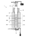
- FIG. 1 illustrates an example of a vertical Bridgman furnace.
- FIG. 1 is a diagram showing the movable range (0 mm-200 mm) of the heating part of a vertical Bridgman furnace.
- FIG. 2 is a diagram showing an example of a sintering apparatus.
- FIG. 2 is a diagram illustrating an example of a thermoelectric conversion module.
- FIG. 13 is a diagram illustrating another example of a thermoelectric conversion module.
- FIG. 1 is a diagram showing the relationship between the position (0 mm-200 mm) of the heating part of a vertical Bridgman furnace and the temperature directly below the crucible.
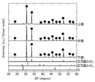
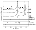
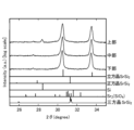
- FIG. 2 shows the powder X-ray diffraction patterns of each sample obtained from the ingot of Example 1.
- FIG. 1 is a diagram showing the movable range (0 mm-200 mm) of the heating part of a vertical Bridgman furnace.
- FIG. 2 is a diagram showing an example of a sintering apparatus.
- FIG. 2
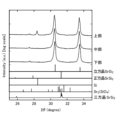
- FIG. 1 shows powder X-ray diffraction patterns of each sample obtained from the ingot of Example 2.
- FIG. 1 shows powder X-ray diffraction patterns of each sample obtained from the ingot of Example 2.
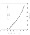
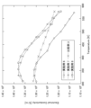
- 1 is a graph showing the relationship between temperature and Seebeck coefficient for test pieces obtained from the ingots of Examples 1 and 2 and for a test piece obtained from the sintered body of Example 3.
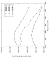
- 1 is a graph showing the relationship between temperature and electrical conductivity in the test pieces obtained from the ingots of Examples 1 and 2 and the test piece obtained from the sintered body of Example 3.
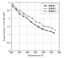
- FIG. 1 is a graph showing the relationship between temperature and power factor for test pieces obtained from the ingots of Examples 1 and 2 and for a test piece obtained from the sintered body of Example 3.
- 1A and 1B are diagrams showing a backscattered electron image and a secondary electron image of the ingot of Example 4 observed with a scanning electron microscope.
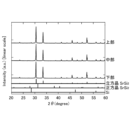
- FIG. 1 shows the powder X-ray diffraction patterns of each sample obtained from the ingot of Example 4.
- FIG. 1 shows the powder X-ray diffraction patterns of each sample obtained from the ingot of Example 4.
- 1A and 1B are diagrams showing a backscattered electron image and a secondary electron image of the ingot of Example 5 observed with a scanning electron microscope.
- FIG. 1 shows the powder X-ray diffraction patterns of each sample obtained from the ingot of Example 5.
- FIG. 1 shows the powder X-ray diffraction patterns of each sample obtained from the ingot of Example 5.
- FIG. 2 is a diagram showing a powder X-ray diffraction pattern of a sample obtained from the ingot of Comparative Example 1.
- FIG. 2 is a diagram showing a powder X-ray diffraction pattern of a sample obtained from the ingot of Comparative Example 1.
- FIG. 1 shows the powder X-ray diffraction patterns of each sample obtained from the ingot of Comparative Example 2.
- 1 is a graph showing the relationship between temperature and Seebeck coefficient for test pieces obtained from the ingots of Examples 4 and 5 and Comparative Example 1.
- FIG. 1 is a graph showing the relationship between temperature and electrical conductivity in test pieces obtained from the ingots of Examples 4 and 5 and Comparative Example 1.
- 1 is a graph showing the relationship between temperature and power factor in test pieces obtained from the ingots of Examples 4 and 5 and Comparative Example 1.
- FIG. 1 shows optical microscope images of the sintered bodies of Examples 6 to 8 observed with an optical microscope and backscattered electron images observed with a scanning electron microscope.
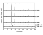
- FIG. 1 shows powder X-ray diffraction patterns of samples obtained from the sintered bodies of Examples 6 to 8.
- FIG. 1 shows powder X-ray diffraction patterns of samples obtained from the sintered bodies of Examples 6 to 8.
- 1 is a graph showing the relationship between temperature and Seebeck coefficient for test pieces obtained from each of the sintered bodies of Examples 6 to 8 and Comparative Example 3.
- 1 is a graph showing the relationship between temperature and electrical conductivity in test pieces obtained from the sintered bodies of Examples 6 to 8 and Comparative Example 3.
- 1 is a graph showing the relationship between temperature and power factor for test pieces obtained from the sintered bodies of Examples 6 to 8 and Comparative Example 3.
- thermoelectric convertible molten composite is composed of a strontium silicide polycrystalline body whose crystal phase is substantially only a cubic SrSi2 phase.
- molten composite means a solidified body obtained by heating composition raw materials to prepare a molten liquid, and then growing a crystal while lowering the temperature of the molten liquid.
- the melt synthetic body according to this embodiment has a cubic SrSi 2 phase content of 99.0% by mass or more, preferably 99.5% by mass or more, as a quantitative value by Rietveld analysis of the powder X-ray diffraction pattern.
- the melt synthetic body according to this embodiment has a tetragonal SrSi 2 phase and a trigonal SrSi 2 phase content of less than 0.1% by mass, preferably less than the detection limit, as a quantitative value by Rietveld analysis of the powder X-ray diffraction pattern.
- the melt synthetic body according to this embodiment has a Sr and Si content of less than 0.1% by mass, preferably less than the detection limit, as a quantitative value by Rietveld analysis of the powder X-ray diffraction pattern.
- the conditions for the powder X-ray diffraction analysis and the Rietveld analysis are as described in the examples described below.
- thermoelectric conversion elements when manufacturing thermoelectric conversion elements using a molten composite, if you try to cut out a thermoelectric conversion component directly from the molten composite, the cut-out part will crumble, making it difficult to obtain a thermoelectric conversion component of the desired shape. For this reason, the molten composite is powdered and then sintered to form a sintered body, from which the thermoelectric conversion components are cut.
- the melt composite according to the present embodiment is composed of a strontium silicide polycrystalline body in which the crystal phase is substantially only a cubic SrSi 2 phase, and therefore the crystal phase is homogeneous, has excellent density, and is also excellent in mechanical properties such as Young's modulus and fracture toughness. Therefore, according to the melt composite according to the present embodiment, a thermoelectric conversion member having a desired shape can be cut out using a wire saw or the like without the cut-out portion collapsing, and as a result, the conventionally performed steps of crushing and sintering can be omitted.
- thermoelectrically convertible sintered body according to this embodiment which will be described later, is made by sintering the powder of the molten composite body according to this embodiment, and therefore has tiny voids and interfaces between powder particles that do not affect the thermoelectric conversion performance.
- the molten composite body according to this embodiment is obtained by growing crystals from a molten liquid obtained by melting the raw material components, and therefore has no voids and no interfaces between powder particles. This difference can be confirmed by an optical microscope (Nomarski contrast) and a reflected electron microscope.
- the melt composite according to this embodiment is composed of a strontium silicide polycrystalline body in which the crystal phase is substantially only a cubic SrSi2 phase, and therefore exhibits semiconductor properties.
- the band gap value (E g ) of the melt composite according to this embodiment is preferably 45.0 meV or more, more preferably 46.0 meV or more, and even more preferably 47.0 meV or more.
- the upper limit of the band gap value (E g ) is not particularly limited, and is, for example, about 60.0 meV.
- the melt composite according to this embodiment is composed of a strontium silicide polycrystalline body in which the crystal phase is substantially only a cubic SrSi 2 phase, it exhibits high thermoelectric conversion performance in the low temperature range (about 0 to 300°C).
- the power factor of the melt composite according to this embodiment at 310K is preferably 2.50 x 10 -3 W/mK 2 or more, more preferably 2.60 x 10 -3 W/mK 2 or more, and even more preferably 2.70 x 10 -3 W/mK 2 or more.
- the upper limit of the power factor at 310K is not particularly limited, and is, for example, about 3.20 W/mK 2 .
- the melt composite according to this embodiment also exhibits excellent mechanical properties.
- the Young's modulus of the melt composite according to this embodiment is preferably 85.0 GPa or more, more preferably 88.0 GPa or more, and even more preferably 90.0 GPa or more.
- the upper limit of the Young's modulus is not particularly limited, and is, for example, about 100.0 GPa.
- the fracture toughness value of the melt composite according to this embodiment is preferably 1.0 MPa ⁇ m 1/2 or more, more preferably 1.2 MPa ⁇ m 1/2 or more, and even more preferably 1.3 MPa ⁇ m 1/2 or more.
- the upper limit of the fracture toughness value is not particularly limited, and is, for example, about 2.0 MPa ⁇ m 1/2 .
- the Young's modulus and fracture toughness value of the melt composite are measured by the method described in the examples below.
- the inventors have confirmed that the higher the content of the tetragonal SrSi2 phase in the crystal phase of the strontium silicide polycrystal constituting the molten composite, the more easily the molten composite is oxidized and deteriorated, and the more difficult it is to cut out the thermoelectric conversion member. This is presumably because tetragonal SrSi2 is easily reactive with moisture.
- the molten composite according to the present embodiment is made of a strontium silicide polycrystal whose crystal phase is substantially only the cubic SrSi2 phase, so it is excellent in durability and easy to cut out the thermoelectric conversion member.
- the molten composite according to this embodiment may contain a dopant.
- dopants include p-type dopants such as Ba, Ag, and Ga; and n-type dopants such as N, P, and Sb.
- the molten synthetic body according to this embodiment can be produced by a production method (melt synthesis method) including a solid-liquid phase reaction process in which a composition raw material containing strontium and silicon is heated at a temperature of 1000° C.
- the composition raw material when melting and synthesizing an alloy, the composition raw material is heated at a temperature equal to or higher than the melting point of the alloy, and the alloy melt is prepared in one step while synthesizing the alloy, and then the crystal is grown while the temperature of the melt is lowered. That is, it is common to prepare the alloy melt while synthesizing the alloy, and grow the crystal from the melt.
- the composition raw material is heated at a temperature higher than the melting point of SrSi 2 (1121° C.), and the SrSi 2 melt is prepared while synthesizing SrSi 2 , and the crystal is grown from the melt.
- the melt of SrSi 2 is not prepared in one step while synthesizing SrSi 2 , but is divided into two steps, a solid-liquid phase reaction step and a melting step, and the synthesis of SrSi 2 is completed at a temperature below the melting point of SrSi 2 , and then the temperature is raised to a temperature equal to or higher than the melting point of SrSi 2 to prepare the melt.
- this manufacturing method it is possible to obtain a homogeneous strontium silicide polycrystalline body (melt synthesis product) whose crystal phase is substantially only a cubic SrSi 2 phase.
- the molten composite produced by the method for producing a molten composite according to the present embodiment exhibits a high band gap value, high thermoelectric conversion performance, and excellent mechanical properties because it is composed of a homogeneous strontium silicide polycrystalline body whose crystal phase is substantially only a cubic SrSi2 phase.
- the method for producing a molten composite according to the present embodiment makes it possible to obtain a large molten composite that is industrially useful.
- composition raw materials used in the method for producing a molten composite according to this embodiment and each step of the method are described in detail below.
- the raw material composition used in producing the molten composite according to this embodiment contains strontium and silicon.
- the strontium in the composition raw material it is preferable to use high-purity strontium with a purity of 2N or more (99% by mass or more). Since strontium becomes liquid in the solid-liquid phase reaction process described below, the size of the strontium in the composition raw material is not particularly limited. However, from the viewpoint of reaction efficiency in the solid-liquid phase reaction process, it is preferable that the strontium in the composition raw material has a size of 3 mm square or less.
- the silicon in the composition raw material it is preferable to use high-purity silicon with a purity of 5N or more (99.999% by mass or more). Since silicon becomes a solid phase in the solid-liquid phase reaction process described below, it is preferable to classify it after powdering it from the viewpoint of reaction efficiency in the solid-liquid phase reaction process.
- the particle size of the silicon powder is preferably 1 to 100 ⁇ m, and more preferably 25 to 75 ⁇ m.
- the atomic ratio of strontium to silicon in the raw material composition is approximately 1:2, and preferably 33.0:67.0 to 34.5:65.5.
- the pressure conditions during melt synthesis may be atmospheric pressure, but a positive pressure of about +0.5 to 3.5 kPa is preferable.
- the atmospheric conditions during melt synthesis are preferably an inert gas atmosphere such as Ar gas, and more preferably a reducing atmosphere in which an inert gas is mixed with about 3 to 7 volume percent hydrogen gas.
- Solid-liquid phase reaction process In the solid-liquid phase reaction process, the composition raw material is heated at a temperature of 1000° C. or higher and lower than the melting point of SrSi 2 to react with strontium and silicon, thereby synthesizing SrSi 2 .
- the heating temperature (solid-liquid reaction temperature) in the solid-liquid reaction step must be lower than the melting temperature in the subsequent step, but as the heating temperature decreases, tetragonal SrSi 2 is more likely to be produced. For this reason, the heating temperature (solid-liquid reaction temperature) is preferably, for example, 1035 to 1055° C.
- the heating rate until the solid-liquid reaction temperature is reached is not particularly limited.
- the heating time in the solid-liquid phase reaction process may be any time that allows the solid-liquid phase reaction between strontium and silicon to be completed, and is preferably, for example, 1 to 20 hours, and more preferably 3 to 10 hours.
- the SrSi2 synthesized in the solid-liquid reaction step is heated at a temperature equal to or higher than the melting point of SrSi2 at which SrSi2 does not decompose, to obtain a homogeneous molten liquid without unevenness.
- the heating temperature (melting temperature) in the melting step is preferably, for example, 1121 to 1150°C, and more preferably 1130 to 1135°C, in order to obtain a homogeneous molten liquid. There are no particular limitations on the rate at which the temperature is raised to the melting temperature.
- the heating time in the melting step may be any time that allows the synthesized SrSi 2 to completely melt, and is preferably, for example, 1 to 10 hours, and more preferably 3 to 5 hours.
- Crystal growth process In the crystal growing step, the temperature of the molten liquid is lowered to grow crystals from the molten liquid, thereby obtaining a strontium silicide polycrystalline body (melt synthesis body).
- the temperature drop rate In order to obtain a strontium silicide polycrystalline body whose crystal phase is substantially composed of only the cubic SrSi2 phase, it is preferable to reduce the temperature drop rate, especially in the initial stage of crystal growth. Specifically, it is preferable to set the temperature drop rate at 0.223 to 4.72 ° C/h until the temperature of the molten liquid reaches 1100 ° C, and to set the temperature drop rate at 0.494 to 10.38 ° C/h until the temperature of the molten liquid reaches 1100 ° C and then reaches 1000 ° C. After the temperature of the molten liquid reaches 1000 ° C, it is slowly cooled to room temperature.
- a temperature gradient such that the temperature at the bottom of the crucible is relatively low and the temperature at the mouth of the crucible is relatively high.
- impurities such as unreacted silicon and Sr2 ( SiO4 ) are segregated at the upper side (the mouth side of the crucible), which is the terminal side of the crystal growth, and by removing this portion, a molten composite body made of a high-purity strontium silicide polycrystalline body can be obtained.
- the solid-liquid reaction process, melting process, and crystal growth process are all performed using a vertical Bridgman furnace.
- a vertical Bridgman furnace allows the temperatures of multiple heaters arranged in the vertical direction to be set independently, making it easy to realize a temperature gradient in which the temperature at the bottom is relatively low and the temperature at the top is relatively high.
- the vertical Bridgman furnace may be one in which the crucible is fixed and the heating section surrounding the crucible is configured to be movable in the vertical direction, or one in which the heating section surrounding the crucible is fixed and the crucible is configured to be movable in the vertical direction.
- FIG. 1 An example of a vertical Bridgman furnace that can be used in the manufacturing method of a molten composite according to this embodiment is shown in FIG. 1.
- the vertical Bridgman furnace 1 shown in FIG. 1 includes a furnace body 10 and a heating section 20 that surrounds the furnace body 10.
- the furnace body 10 has a cylindrical quartz glass tube 11 arranged so that its axis is vertical, a graphite sample stage 12 arranged inside the quartz glass tube 11 on which the crucible 30 and quartz cover 31 are placed, a heat shield 13 arranged inside and above the quartz glass tube 11, and a thermocouple 14 for measuring the temperature directly below the crucible.
- a pressure reduction mechanism for reducing the pressure inside the quartz glass tube 11 and an Ar gas supply mechanism for supplying Ar gas into the quartz glass tube 11 are connected to the quartz glass tube 11.
- the heating section 20 has three heaters 21A, 21B, and 21C arranged vertically around the outer periphery of the quartz glass tube 11, a heat insulating material 22 covering the heaters 21A, 21B, and 21C, and thermocouples 23A, 23B, and 23C for measuring the temperatures of the heaters 21A, 21B, and 21C, respectively.
- the temperatures of the heaters 21A, 21B, and 21C can be set independently, and when producing a molten composite, a temperature gradient is formed in which the temperature at the bottom (heater 21C side) is relatively low and the temperature at the top (heater 21A side) is relatively high.
- the vertical Bridgman furnace 1 shown in FIG. 1 is configured so that the heating section 20 can be moved vertically.
- the heating section 20 is configured so that it can be moved vertically from the bottom end, which is a position of 0 mm (left side of FIG. 2), to the top end, which is a position of 200 mm (right side of FIG. 2).
- By moving the heating section 20 downward the temperature of the crucible can be increased, and by moving the heating section 20 upward, the temperature of the crucible can be decreased.
- thermoelectric convertible sintered body (hereinafter, simply referred to as the "sintered body") is composed of a strontium silicide polycrystalline body whose crystal phase is substantially only a cubic SrSi2 phase, and can be obtained by sintering the melt synthesis body according to this embodiment described above.
- the melt synthesis body according to this embodiment has excellent sinterability, so a dense sintered body without cracks can be obtained.
- the sintered body according to this embodiment as well as the melt synthetic body according to this embodiment, has a cubic SrSi 2 phase content of 99.0% by mass or more, preferably 99.5% by mass or more, as a quantitative value by Rietveld analysis of the powder X-ray diffraction pattern.
- the sintered body according to this embodiment has a tetragonal SrSi 2 phase and a trigonal SrSi 2 phase content of less than 0.1% by mass, preferably less than the detection limit, as a quantitative value by Rietveld analysis of the powder X-ray diffraction pattern.
- the sintered body according to this embodiment has a Sr content of less than 0.1% by mass, preferably less than the detection limit, as a quantitative value by Rietveld analysis of the powder X-ray diffraction pattern.
- the sintered body according to this embodiment has a Si content of less than 0.8% by mass, more preferably less than 0.1% by mass, more preferably less than the detection limit, as a quantitative value by Rietveld analysis of the powder X-ray diffraction pattern.
- the sintered body according to this embodiment exhibits the characteristics of a semiconductor, similar to the melt-synthesized body according to this embodiment.
- the band gap value (E g ) of the sintered body according to this embodiment is preferably 50.0 meV or more, more preferably 51.0 meV or more, and even more preferably 52.0 meV or more.
- the upper limit of the band gap value (E g ) is not particularly limited, and is, for example, about 70.0 meV.
- the sintered body according to this embodiment like the melt-synthesized body according to this embodiment, exhibits high thermoelectric conversion performance in the low temperature range (about 0 to 300°C).
- the power factor of the sintered body according to this embodiment at 310K is preferably 2.35 ⁇ 10 ⁇ 3 W/mK 2 or more, more preferably 2.40 ⁇ 10 ⁇ 3 W/mK 2 or more, and even more preferably 2.45 ⁇ 10 ⁇ 3 W/mK 2 or more.
- the upper limit of the power factor at 310K is not particularly limited, and is, for example, about 3.00 ⁇ 10 ⁇ 3 W/mK 2 .
- the sintered body according to this embodiment exhibits excellent mechanical properties, similar to the melt-synthesized body according to this embodiment.
- the Young's modulus of the sintered body according to this embodiment is preferably 80.0 GPa or more, more preferably 85.0 GPa or more, and even more preferably 86.0 GPa or more.
- the upper limit of the Young's modulus is not particularly limited, and is, for example, about 100.0 GPa.
- the fracture toughness value of the sintered body according to this embodiment is preferably 1.3 MPa ⁇ m 1/2 or more, more preferably 1.5 MPa ⁇ m 1/2 or more, and even more preferably 1.6 MPa ⁇ m 1/2 or more.
- the upper limit of the fracture toughness value is not particularly limited, and is, for example, about 2.0 MPa ⁇ m 1/2 .
- the sintered body according to this embodiment can be produced by a production method including a sintering step of sintering the molten composite body according to the embodiment described above.
- the particle size of the powder of the molten composite body is preferably 10 to 100 ⁇ m, and more preferably 25 to 45 ⁇ m.
- pressure compression sintering methods such as hot press sintering (HP), hot isostatic pressure sintering (HIP), and spark plasma sintering can be used, with spark plasma sintering being preferred.
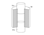
- a jig as shown in Figure 3 is used for pressure compression sintering.
- the powder of the molten composite is first filled into the space surrounded by the graphite die 50 and graphite punches 51a and 51b shown in Figure 3.
- sintering is performed using a sintering device such as a discharge plasma sintering device. Sintering is preferably performed under reduced pressure and in an inert gas atmosphere.
- the sintering pressure for pressure compression sintering is preferably 60 to 150 MPa. By setting the sintering pressure to 60 MPa or more, it tends to be easier to obtain a sintered body with sufficient density (for example, a relative density of 97% or more relative to the theoretical density).
- the sintering temperature for pressure compression sintering is preferably 850 to 950°C.
- the sintering temperature is preferably 850 to 950°C.
- 850°C or higher it tends to be easier to obtain a sintered body with sufficient density.
- 950°C or lower damage to the strontium silicide polycrystalline body and the occurrence of voids are suppressed, and the scattering of strontium tends to be prevented.
- thermoelectric conversion element includes a thermoelectric conversion part formed from the molten composite body or sintered body according to this embodiment described above, and a first electrode and a second electrode provided on the thermoelectric conversion part.
- the thermoelectric conversion section can be a thermoelectric conversion member obtained by cutting the molten composite or sintered body according to this embodiment to a desired size using a wire saw or the like.
- the molten composite body according to this embodiment is homogeneous and has excellent density and mechanical properties (Young's modulus, fracture toughness, etc.), so that the thermoelectric conversion member can be cut out directly from the molten composite body without the cut-out portion collapsing.
- the molten composite body according to this embodiment also has excellent sinterability, so that a sintered body can be obtained that is free of cracks, has excellent density, and has excellent mechanical properties (Young's modulus, fracture toughness, etc.). This tends to improve the yield when cutting out thermoelectric conversion members from a sintered body.
- the method of forming the first electrode and the second electrode is not particularly limited.
- One example is a method of plating the molten composite or sintered body with electroless nickel plating or the like, or a method of applying a conductive paste to the molten composite or sintered body and then firing it.
- Another example is a method of laminating a metal powder for forming electrodes, a powder of the molten composite, and a metal powder for forming electrodes in this order, and then obtaining a sintered body by pressure compression sintering, thereby simultaneously forming the electrodes when manufacturing the sintered body.
- thermoelectric conversion module according to the present embodiment includes the thermoelectric conversion element according to the present embodiment described above.
- the configuration of the thermoelectric conversion module according to the present embodiment is not particularly limited, and any configuration such as a ⁇ type or a uni-leg type can be adopted.
- thermoelectric conversion module One example of the thermoelectric conversion module according to this embodiment is shown in FIG. 4.
- electrodes 101, 111 are provided at the upper ends of the juxtaposed n-type thermoelectric conversion section 100 and p-type thermoelectric conversion section 110, and electrodes 102, 112 are provided at the lower ends.
- the electrodes 101, 111 are connected to form an integrated electrode, while the electrodes 102, 112 are configured separately.
- the molten composite or sintered body according to this embodiment is used, for example, in the p-type thermoelectric conversion section 110.
- thermoelectric conversion module shown in FIG. 4, by heating the electrodes 101, 111 and dissipating heat from the electrodes 102, 112, a positive temperature difference (Th-Tc) occurs between the electrodes 101, 111 and the electrodes 102, 112, and thermally excited carriers cause the p-type thermoelectric conversion unit 110 to have a higher potential than the n-type thermoelectric conversion unit 100. At this time, by connecting a load 130 between the electrodes 102 and 112, a current flows from the p-type thermoelectric conversion unit 110 to the n-type thermoelectric conversion unit 100.
- Thi-Tc positive temperature difference
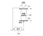
- thermoelectric conversion module Another example of a thermoelectric conversion module according to this embodiment is shown in FIG. 5.
- an electrode 121 is provided at the upper end of the thermoelectric conversion section 120, and an electrode 122 is provided at the lower end.
- thermoelectric conversion module shown in FIG. 5, by heating the electrode 121 side and dissipating heat from the electrode 122 side, a positive temperature difference (Th-Tc) occurs between the electrodes 121 and 122, and the electrode 121 side has a higher potential than the electrode 122 side. At this time, by connecting the load 130 between the electrodes 121 and 122, a current flows from the electrode 121 side to the electrode 122 side.
- Th-Tc positive temperature difference
- Example 1 [Preparation of ingredients] Irregularly shaped strontium (purity 2N, manufactured by Kojundo Chemical Laboratory Co., Ltd.) that had been stored in oil was washed three times with acetone in a glove box under an Ar gas atmosphere, and then cut into 1-3 mm squares.
- a crucible made of boron nitride (BN) (manufactured by Denka Co., Ltd.) was prepared as the crucible.
- the internal height of the crucible was 70 mm, and the upper side from the mouth to a position 56.5 mm in the depth direction was approximately cylindrical, and the bottom side had an internal shape of approximately cone to facilitate the formation of a temperature gradient.
- the inner diameter of the mouth was 38.75 mm, the inner diameter at a position 56.5 mm in the depth direction from the mouth was 31.2 mm, and the inner diameter of the bottom was 3 mm.
- a mold release agent White Seven, manufactured by Odec Co., Ltd.
- ethanol diluted with ethanol was poured into the crucible to coat the inner wall, and the crucible was dried in a drying furnace (80°C, 1 hour or more), and then baked in an electric furnace (1140°C, 10 hours). Then, BN spray (manufactured by Kaken Tech Co., Ltd.) was applied to the entire inner wall.
- alumina lid custom-made by Nikkato Corporation was prepared as the lid for the crucible.
- the outer surface of the lid was coated with the release agent described above.
- the heating part was first fixed at a position 123 mm from the bottom end, and the temperature of the upper heater (heater 21A) and the middle heater (heater 21B) was set to 1130°C, while the temperature of the lower heater (heater 21C) was set to 890°C.
- the temperature directly below the crucible reached 1040°C after 90 minutes. This state was maintained for 10 hours to allow the solid-liquid phase reaction of the composition raw materials to proceed, and SrSi 2 was synthesized (solid-liquid phase reaction process).
- the heating part was moved to the bottom end (0 mm position) over 15 minutes. At that time, the temperature directly below the crucible was 1131° C. The state was kept for 5 hours to obtain a molten liquid of SrSi 2 (melting process).
- the temperature of the molten liquid was lowered by moving the heating part from the bottom end (0 mm position) to the top end (200 mm position) at a moving speed of 3.6 mm/h, and a crystal was grown from the molten liquid (crystal growth process).
- the temperature drop rate of the molten liquid was 1.84°C/h on average (minimum: 1.23°C/h, maximum: 2.36°C/h) until it reached 1100°C, and after reaching 1100°C, it was 4.32°C/h on average (minimum: 3.01°C/h, maximum: 5.19°C/h) until it reached 1000°C.
- the temperatures of the upper, middle, and lower heaters were all set to 600°C, and the temperature directly below the crucible was allowed to drop to 600°C over a period of five hours.
- the temperatures of the upper, middle, and lower heaters were then all set to 25°C, and the temperature directly below the crucible was allowed to drop to 25°C over a period of five hours, after which the ingot was removed from the crucible. No voids were visually observed in the resulting ingot.
- the crystal phase of the upper sample contained Si phase and Sr2 ( SiO4 ) phase, while the crystal phase of the middle and lower samples consisted only of cubic SrSi2 phase.
- These middle and lower samples can be the melt composites according to the present embodiment described above.
- Example 2 [Melt synthesis of polycrystalline strontium silicide]
- an ingot was obtained in the same manner as in Example 1, except that the melt synthesis conditions were changed as follows.
- the heating part was fixed at a position 106 mm from the bottom end, and the temperature of the upper heater (heater 21A) and the middle heater (heater 21B) was set to 1130 ° C., and the temperature of the lower heater (heater 21C) was set to 890 ° C.
- the temperature directly below the crucible reached 1050 ° C. after 90 minutes. This state was maintained for 10 hours to allow the solid-liquid phase reaction of the composition raw materials to proceed, and SrSi 2 was synthesized (solid-liquid phase reaction process).
- the heating part was moved to the bottom end (0 mm position) over 15 minutes. At that time, the temperature directly below the crucible was 1133° C. The state was kept for 5 hours to obtain a molten liquid of SrSi 2 (melting process).
- the temperature of the molten liquid was gradually lowered by moving the heating part from the bottom end (0 mm position) to the top end (200 mm position) at a moving speed of 1.08 mm/h, and a crystal was grown from the molten liquid (crystal growth process).
- the cooling rate of the molten liquid was an average of 0.617°C/h (minimum: 0.445°C/h, maximum: 0.745°C/h) until it reached 1100°C, and after reaching 1100°C, it was an average of 1.152°C/h (minimum: 0.988°C/h, maximum: 1.339°C/h) until it reached 1015°C.
- the temperatures of the upper, middle, and lower heaters were all set to 600°C, and the temperature directly below the crucible was allowed to drop to 600°C over a period of five hours.
- the temperatures of the upper, middle, and lower heaters were then all set to 25°C, and the temperature directly below the crucible was allowed to drop to 25°C over a period of five hours, after which the ingot was removed from the crucible. No voids were visually observed in the resulting ingot.
- the crystal phase of the upper sample contained the Si phase and the Sr2 ( SiO4 ) phase, while the crystal phase of the middle and lower samples consisted only of the cubic SrSi2 phase.
- These middle and lower samples can be the melt composites according to the present embodiment described above.
- Example 3 [Production of sintered body] In a glove box with an Ar gas atmosphere, a part of the lower sample of Example 1 was crushed in a mortar. After crushing, the crushed material was classified using a stainless steel sieve to obtain a sample powder having a particle size of 25 to 45 ⁇ m.
- the graphite die was then placed in a spark plasma sintering apparatus (Ed-PAS III, manufactured by Elenix Co., Ltd.), the press pressure was increased to 100 MPa, and spark plasma sintering was performed in an Ar atmosphere.
- the temperature conditions during sintering were as follows. First, the temperature was raised from room temperature to 500°C over 1 minute, and then to 800°C over 1 minute. Next, the temperature was raised at a heating rate of 30°C/min until it reached the sintering temperature of 920°C, and was held at 920°C for 10 minutes. Next, the temperature was lowered at a heating rate of 50°C/min until it reached 600°C, during which the press pressure was gradually reduced to 42 MPa. After that, it was allowed to cool to room temperature. The temperature was measured by measuring the temperature of the graphite die, using a K thermocouple from room temperature to 580°C, and an infrared radiation thermometer at temperatures above that.
- the attached carbon paper was removed with sandpaper to obtain a sintered body.
- the shape of the obtained sintered body was cylindrical (top and bottom were circles with a diameter of 10 mm, and the height was 5 mm).
- thermoelectric conversion performance The lower samples of Examples 1 and 2 were cut with a wire saw perpendicular to the height direction of the crucible to obtain a roughly disk-shaped sample with a thickness of 2 mm. Furthermore, a test piece with a size of 2 mm x 2 mm x 7.5 mm was cut from the roughly disk-shaped sample using a wire saw. Moreover, the sintered body of Example 3 was cut with a wire saw perpendicular to the axial direction of the cylinder to obtain a disk-shaped sample with a thickness of 2 mm. Furthermore, a test piece with a size of 2 mm x 2 mm x 7.5 mm was cut from the disk-shaped sample using a wire saw.
- each of the test pieces of Examples 1 to 3 the Seebeck coefficient and electrical conductivity were measured in the temperature range of 300 to 600 K using a thermoelectric property evaluation device (ZEM-3, manufactured by Advance Riko Co., Ltd.). Then, the power factor was calculated based on the obtained Seebeck coefficient and electrical conductivity.
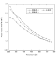
- the Seebeck coefficient, electrical conductivity, and power factor of each of the test pieces of Examples 1 to 3 are shown in Figures 9 to 11. As can be seen from Figure 11, each of the test pieces of Examples 1 to 3 had high thermoelectric conversion performance in the low temperature region.
- the power factor at 310 K was 2.736 x 10 -3 W/mK 2 for Example 1, 2.919 x 10 -3 W/mK 2 for Example 2, and 2.845 x 10 -3 W/mK 2 for Example 3.
- Example 4 [Melt synthesis of polycrystalline strontium silicide]
- the crucible for loading the raw material was changed to an alumina crucible (manufactured by Nikkato Corporation) with boron nitride pressed onto the inner surface, the gas filled in the heating furnace was changed to Ar gas containing 5% by volume of hydrogen gas, and the melt synthesis conditions were changed as follows. An ingot was obtained in the same manner as in Example 1.
- the heating unit was first fixed at a position 123 mm from the bottom end, and the temperature of the upper heater (heater 21A) and the middle heater (heater 21B) was set to 1130°C, while the temperature of the lower heater (heater 21C) was set to 890°C.
- the temperature directly below the crucible reached 1035°C after 90 minutes. This state was maintained for 10 hours to allow the solid-liquid phase reaction of the composition raw materials to proceed, and SrSi2 was synthesized (solid-liquid phase reaction process).
- the heating part was moved to the bottom end (0 mm position) over 15 minutes. At that time, the temperature directly below the crucible was 1130° C. The state was kept for 5 hours to obtain a molten liquid of SrSi 2 (melting process).
- the temperature of the molten liquid was gradually lowered by moving the heating part from the bottom end (0 mm position) to the top end (200 mm position) at a moving speed of 3.6 mm/h, and a crystal was grown from the molten liquid (crystal growth process).
- the temperature drop rate of the molten liquid was an average of 1.84°C/h (minimum: 1.23°C/h, maximum: 2.36°C/h) until it reached 1100°C, and after reaching 1100°C, it was an average of 4.32°C/h (minimum: 3.01°C/h, maximum: 5.19°C/h) until it reached 1000°C.
- FIG. 12 shows a backscattered electron image and a secondary electron image of the resulting ingot observed with a scanning electron microscope (SEM).
- the crystal phase of the upper sample contained a Si phase
- the crystal phase of the middle and lower samples consisted only of a cubic SrSi 2 phase.
- Example 5 [Melt synthesis of polycrystalline strontium silicide]
- an ingot was obtained in the same manner as in Example 4, except that the melt synthesis conditions were changed as follows.
- the heating part was fixed at a position 106 mm from the bottom end, and the temperature of the upper heater (heater 21A) and the middle heater (heater 21B) was set to 1130 ° C., and the temperature of the lower heater (heater 21C) was set to 890 ° C.
- the temperature directly below the crucible reached 1035 ° C. after 90 minutes. This state was maintained for 10 hours to allow the solid-liquid phase reaction of the composition raw materials to proceed, and SrSi 2 was synthesized (solid-liquid phase reaction process).
- the heating part was moved to the bottom end (0 mm position) over 15 minutes. At that time, the temperature directly below the crucible was 1130° C. The state was kept for 5 hours to obtain a molten liquid of SrSi 2 (melting process).
- the temperature of the molten liquid was gradually lowered by moving the heating part from the bottom end (0 mm position) to the top end (200 mm position) at a moving speed of 1.08 mm/h, and a crystal was grown from the molten liquid (crystal growth process).
- the cooling rate of the molten liquid was an average of 0.617°C/h (minimum: 0.445°C/h, maximum: 0.745°C/h) until it reached 1100°C, and after reaching 1100°C, it was an average of 1.152°C/h (minimum: 0.988°C/h, maximum: 1.339°C/h) until it reached 1015°C.
- the crystal phase of the upper sample contained a Si phase
- the crystal phase of the middle and lower samples consisted only of a cubic SrSi 2 phase.
- Comparative Example 1 [Melt synthesis of polycrystalline strontium silicide]
- an ingot was obtained in the same manner as in Example 4, except that the atomic ratio of strontium to silicon was changed to 33.8:66.2, the fill gas in the heating furnace was changed to Ar gas, and the melt synthesis conditions were changed as follows.
- the heating part was fixed at a position 197 mm from the bottom end, and the temperature of the upper heater (heater 21A) was set to 1100°C, the temperature of the middle heater (heater 21B) to 1130°C, and the temperature of the lower heater (heater 21C) to 890°C.
- the temperature directly below the crucible reached 900°C after 90 minutes. This state was maintained for 3 hours to allow the solid-liquid phase reaction of the composition raw materials to proceed, and SrSi2 was synthesized.
- the heating part was moved to the bottom end (0 mm position) over 15 minutes. At that time, the temperature directly below the crucible was 1130° C. The state was kept for 3 hours to obtain a molten liquid of SrSi 2 .
- the temperature of the molten liquid was gradually lowered by moving the heating part from the bottom end (0 mm position) to the top end (200 mm position) at a moving speed of 7.2 mm/h, and a crystal was grown from the molten liquid (crystal growth process).
- the temperature drop rate of the molten liquid was an average of 2.13°C/h (minimum: 0.88°C/h, maximum: 3.35°C/h) until it reached 1100°C, and after reaching 1100°C, it was an average of 7.02°C/h (minimum: 3.56°C/h, maximum: 9.73°C/h) until it reached 1000°C.
- the temperatures of the upper, middle, and lower heaters were all set to 600°C, and the temperature directly below the crucible was allowed to drop to 600°C over a period of five hours.
- the temperatures of the upper, middle, and lower heaters were then all set to 25°C, and the temperature directly below the crucible was allowed to drop to 25°C over a period of five hours, after which the ingot was removed from the crucible.
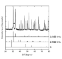
- FIG. 16A and 16B show the powder X-ray diffraction patterns of the sample of Comparative Example 1. As shown in Fig. 16A and 16B, tetragonal SrSi2 was confirmed in the sample of Comparative Example 1.
- the crystalline phase of the sample of Comparative Example 1 contained 1.88 wt % of the tetragonal SrSi 2 phase.
- the heating unit was fixed at the lower end (0 mm position), and the temperature of the upper heater (heater 21A) and the middle heater (heater 21B) was set to 1130°C, while the temperature of the lower heater (heater 21C) was set to 890°C.
- the temperature directly below the crucible reached 1130°C after 90 minutes. This state was maintained for 5 hours, and a molten liquid of SrSi2 was obtained while synthesizing SrSi2 .
- the temperature of the molten liquid was gradually lowered by moving the heating part from the bottom end (0 mm position) to the top end (200 mm position) at a speed of 3.6 mm/h, and a crystal was grown from the molten liquid.
- the cooling rate of the molten liquid was an average of 1.84°C/h (minimum: 1.23°C/h, maximum: 2.36°C/h) until it reached 1100°C, and after reaching 1100°C, it was an average of 4.32°C/h (minimum: 3.01°C/h, maximum: 5.19°C/h) until it reached 1000°C.
- the temperatures of the upper, middle, and lower heaters were all set to 600°C, and the temperature directly below the crucible was allowed to drop to 600°C over a period of five hours.
- the temperatures of the upper, middle, and lower heaters were then all set to 25°C, and the temperature directly below the crucible was allowed to drop to 25°C over a period of five hours, after which the ingot was removed from the crucible.
- Powder samples 1 and 2 were collected from two different locations on the lower side (bottom side of the crucible) of the obtained ingot, which is the starting side of the crystal growth. Then, powder X-ray diffraction analysis was performed in the same manner as in Example 1.
- thermoelectric conversion performance The lower samples of Examples 4 and 5 were cut perpendicularly to the height direction of the crucible with a wire saw to obtain roughly disk-shaped samples with a thickness of 2 mm. Furthermore, test pieces with dimensions of 2 mm x 2 mm x 7.5 mm were cut from the roughly disk-shaped samples using a wire saw. Test pieces were also cut from the ingot of Comparative Example 1 in the same manner.
- each test piece of Examples 4 and 5 and Comparative Example 1 the Seebeck coefficient and electrical conductivity were measured in the temperature range of 300 to 600 K using a thermoelectric property evaluation device (ZEM-3, manufactured by Advance Riko Co., Ltd.). Then, the power factor was calculated based on the obtained Seebeck coefficient and electrical conductivity.
- the Seebeck coefficient, electrical conductivity, and power factor of each test piece of Examples 4 and 5 and Comparative Example 1 are shown in Figures 18 to 20. As can be seen from Figure 20, each test piece of Examples 4 and 5 had high thermoelectric conversion performance in the low temperature region.
- the power factor at 310 K was 2.707 x 10 -3 W/mK 2 for Example 4, 2.893 x 10 -3 W/mK 2 for Example 5, and 2.275 x 10 -3 W/mK 2 for Comparative Example 1.
- Examples 6 to 8 [Production of sintered body]
- a part of the lower sample of Example 5 was used, and a sintered body was obtained in the same manner as in Example 3, except that the temperature conditions during sintering were changed as follows.
- the temperature was first raised from room temperature to 500°C over one minute, and then raised to 800°C over one minute. Next, the temperature was raised at a heating rate of 30°C/min until it reached the sintering temperature of 890°C (Example 6), 920°C (Example 7), or 950°C (Example 8), and each sintering temperature was held for 10 minutes. Next, the temperature was lowered at a cooling rate of 50°C/min until it reached 600°C, during which the pressing pressure was gradually reduced to 42 MPa. After that, it was allowed to cool to room temperature, and a sintered body was obtained.
- the crystal phase of the sintered body of Example 8 contained a small amount of Si phase, while the crystal phase of the sintered bodies of Examples 6 and 7 consisted of only cubic SrSi 2 phase.
- Comparative Example 3 [Production of sintered body]
- a sintered body was obtained in the same manner as in Example 3, except that Sample 1 of Comparative Example 2 was used.
- thermoelectric conversion performance The sintered bodies of Examples 6 to 8 and Comparative Example 3 were cut perpendicular to the axial direction of the cylinder with a wire saw to obtain disk-shaped samples with a thickness of 2 mm. Furthermore, test pieces with dimensions of 2 mm x 2 mm x 7.5 mm were cut out from the disk-shaped samples using the wire saw.
- each test piece of Examples 6 to 8 and Comparative Example 3 the Seebeck coefficient and electrical conductivity were measured in the temperature range of 300 to 600 K using a thermoelectric property evaluation device (ZEM-3, manufactured by Advance Riko Co., Ltd.). Then, the power factor was calculated based on the obtained Seebeck coefficient and electrical conductivity.
- the Seebeck coefficient, electrical conductivity, and power factor of each test piece of Examples 6 to 8 and Comparative Example 3 are shown in Figures 23 to 25. As can be seen from Figure 25, each test piece of Examples 6 to 8 had high thermoelectric conversion performance in the low temperature region.
- the power factor at 310 K was 2.401 x 10 -3 W/mK 2 for Example 6, 2.571 x 10 -3 W/mK 2 for Example 7, 2.442 x 10 -3 W/mK 2 for Example 8, and 1.814 x 10 -3 W/mK 2 for Comparative Example 3.
Landscapes
- Chemical & Material Sciences (AREA)
- Engineering & Computer Science (AREA)
- Organic Chemistry (AREA)
- Inorganic Chemistry (AREA)
- Ceramic Engineering (AREA)
- Manufacturing & Machinery (AREA)
- Materials Engineering (AREA)
- Structural Engineering (AREA)
- Silicon Compounds (AREA)
Abstract
ストロンチウムシリサイド多結晶体から構成される熱電変換性溶融合成体又は熱電変換性焼結体であって、粉末X線回折パターンのリートベルト解析による定量値として、立方晶SrSi2相の含有率が99.0質量%以上であり、正方晶SrSi2相及び三方晶SrSi2相の含有率がいずれも0.1質量%未満である熱電変換性溶融合成体又は熱電変換性焼結体、及びその製造方法を提供する。また、上記の熱電変換性溶融合成体又は熱電変換性焼結体を用いた熱電変換素子、及び上記の熱電変換素子を備える熱電変換モジュールを提供する。
Description
本発明は、熱電変換性溶融合成体及びその製造方法、熱電変換性焼結体及びその製造方法、熱電変換素子、並びに熱電変換モジュールに関する。
従来、各種設備等から排出される熱(排熱)をエネルギーとして有効利用するため、熱電変換材料を用いて発電する試みがなされている。
これまで、0~300℃程度の低温域において高い熱電変換性能を示す熱電変換材料として、ビスマステルライド(Bi2Te3)が主に実用化されている。しかし、構成元素であるビスマス及びテルルは、毒性があり環境負荷が大きい上に、地殻埋蔵量が少ないという問題があった。
このような背景から、環境負荷が小さく、地殻埋蔵量が豊富な元素から構成され、かつ、低温域において高い熱電変換性能を示す熱電変換材料の開発が望まれている。近年、そのような熱電変換材料の1つとして、ストロンチウムシリサイド(SrSi2)が研究されている。SrSi2には、立方晶、正方晶、三方晶等の結晶形が存在することが知られており、そのうち立方晶SrSi2(α-SrSi2とも称される)のみが半導体の特性を示すことから、熱電変換材料として期待されている。
特許文献1には、ストロンチウム及びシリコンを含有する組成原料をアーク溶解して珪化ストロンチウム合金を得た後、この珪化ストロンチウム合金の粉末を焼結することにより、主な結晶相が立方晶SrSi2相である珪化ストロンチウムバルク多結晶体(焼結体)を得たことが記載されている。ただし、特許文献1の珪化ストロンチウムバルク多結晶体は、その嵩密度及び含有酸素量を特徴とするものであり、熱電変換性能の測定データは示されていない。
また、特許文献2には、特許文献1と同様にして珪化ストロンチウムバルク多結晶体(焼結体)を得た後、この珪化ストロンチウムバルク多結晶体をターゲットとしたスパッタ法により、立方晶SrSi2相を主体に三方晶SrSi2相及び/又はSiを含有する薄膜を得たことが記載されている。特許文献2には、得られた薄膜の300℃における熱電変換性能も示されている。
また、非特許文献1には、一般的に知られている垂直ブリッジマン法により、ストロンチウム及びシリコンを含有する組成原料をSrSi2の融点以上の温度で加熱して融解液を調製し、その融解液から結晶を育成させることにより、主な結晶相が立方晶SrSi2相であるストロンチウムシリサイド多結晶体(溶融合成体)を得たことが記載されている。
また、非特許文献2には、市販のSrSi2のインゴットを粉砕した後、得られた粉体を放電プラズマ焼結法にて1073Kの温度で焼結することにより、主な結晶相が立方晶SrSi2相であるストロンチウムシリサイド焼結体を得たことが記載されている。
D. Shiojiri et al., J. Appl. Phys., 129, 115101 (2021)
K. Hashimoto et al., J. Appl. Phys., 102, 063703 (2007)
特許文献1及び2のように、珪化ストロンチウム合金の合成をアーク溶解法により行う場合、組成原料が急激に局所加熱されることになるため、得られる珪化ストロンチウム合金はクラック及びボイドが多く存在するものとなる。また、アーク溶解法では温度制御が難しいため、組成原料の組成と一致した珪化ストロンチウム合金を得ることが困難である。実際、特許文献1の実施例2では、組成原料におけるストロンチウムとシリコンとの原子量比が1:2であるにもかかわらず、得られた珪化ストロンチウム合金におけるストロンチウムとシリコンとの原子量比は30:70となっている。さらに、特許文献2で得られた薄膜は、300℃における出力因子の最高値が実施例4の0.46×10⁻³W/mK2(膜厚:1400nm)と極めて低いものである。特許文献2のような薄膜状の熱電変換材料の場合、発生する電力が微小になるため、用途が限られると考えられる。
一方、非特許文献1のように通常の垂直ブリッジマン法によりストロンチウムシリサイド多結晶体を溶融合成する場合、組成原料の組成と一致したストロンチウムシリサイド多結晶体(溶融合成体)を得ることが可能である。しかし、本発明者らが非特許文献1の製造方法で得られたストロンチウムシリサイド多結晶体を分析したところ、粉末X線回折パターンのリートベルト解析による定量値として、3質量%程度の正方晶SrSi2相(β-SrSi2とも称される)が含まれていることを確認した。正方晶SrSi2は、半導体ではなく金属レベルの導体である。非特許文献1には、得られたストロンチウムシリサイド多結晶体のバンドギャップ値が13.1meVであったと記載されており、このバンドギャップ値の低さは、ストロンチウムシリサイド多結晶体に正方晶SrSi2相が含まれているためと考えられる。このようにバンドギャップ値が低いストロンチウムシリサイド多結晶体は、半導体の熱電変換材料としては不適当である。
また、非特許文献2には、市販のインゴットから製造されたストロンチウムシリサイド焼結体の出力因子の値が、低温域の331Kにおいて1.19×10⁻³W/mK2であったと記載されており、実用化には依然として不十分である。
ところで、熱電変換モジュールに使用される熱電変換素子の熱電変換部を構成する材料(熱電変換部材と称する)を製造する場合、アーク溶解法や溶融合成法によって得た熱電変換性インゴットを粉砕した後に焼結して焼結体とし、この焼結体から所望の形状及び大きさの熱電変換部材を切り出すことが一般的である。この点、熱電変換性インゴット自体から熱電変換部材を直接切り出すことができれば、粉砕や焼結の工程を省略することができ、便宜である。しかし、特許文献1及び2に記載のアーク溶解法では、得られる珪化ストロンチウム合金にクラック及びボイドが多く存在するため、熱電変換部材の切り出しに使用することができない。一方、非特許文献1に記載の溶融合成法では、クラック及びボイドのないストロンチウムシリサイド多結晶体(溶融合成体)を得ることが可能である。しかし、本発明者らが確認したところ、ストロンチウムシリサイド多結晶体中に正方晶SrSi2が多く含まれていると、熱電変換部材を切り出す際に切り出し部分が崩れてしまい、所望の形状及び大きさの熱電変換部材を得ることが困難であった。
本発明は、上記に鑑みてなされたものであり、低温域(0~300℃程度)の熱電変換材料として有用な非焼結体であって、所望の形状及び大きさの熱電変換部材を切り出し可能な性状を有する新規な熱電変換性溶融合成体及びその製造方法、低温域の熱電変換材料として有用であり、かつ、所望の形状及び大きさの熱電変換部材を切り出し可能な熱電変換性焼結体及びその製造方法、上記の熱電変換性用溶融合成体又は上記の熱電変換性焼結体を用いた熱電変換素子、並びに上記の熱電変換素子を備える熱電変換モジュールを提供することを課題とする。
上記課題を解決するための具体的な手段には、以下の実施態様が含まれる。
<1> ストロンチウムシリサイド多結晶体から構成される熱電変換性溶融合成体であって、
粉末X線回折パターンのリートベルト解析による定量値として、立方晶SrSi2相の含有率が99.0質量%以上であり、正方晶SrSi2相及び三方晶SrSi2相の含有率がいずれも0.1質量%未満である熱電変換性溶融合成体。
<1> ストロンチウムシリサイド多結晶体から構成される熱電変換性溶融合成体であって、
粉末X線回折パターンのリートベルト解析による定量値として、立方晶SrSi2相の含有率が99.0質量%以上であり、正方晶SrSi2相及び三方晶SrSi2相の含有率がいずれも0.1質量%未満である熱電変換性溶融合成体。
<2> 粉末X線回折パターンのリートベルト解析による定量値として、Siの含有率が0.1質量%未満である、<1>に記載の熱電変換性溶融合成体。
<3> 粉末X線回折パターンのリートベルト解析による定量値として、Srの含有率が0.1質量%未満である、<1>又は<2>に記載の熱電変換性溶融合成体。
<4> 310Kにおける出力因子が2.50×10⁻³W/mK2以上である、<1>~<3>のいずれか1項に記載の熱電変換性溶融合成体。
<5> バンドギャップが45.0meV以上である、<1>~<4>のいずれか1項に記載の熱電変換性溶融合成体。
<6> ストロンチウムシリサイド多結晶体から構成される熱電変換性焼結体であって、
粉末X線回折パターンのリートベルト解析による定量値として、立方晶SrSi2相の含有率が99.0質量%以上であり、正方晶SrSi2相及び三方晶SrSi2相の含有率がいずれも0.1質量%未満である熱電変換性焼結体。
粉末X線回折パターンのリートベルト解析による定量値として、立方晶SrSi2相の含有率が99.0質量%以上であり、正方晶SrSi2相及び三方晶SrSi2相の含有率がいずれも0.1質量%未満である熱電変換性焼結体。
<7> <1>~<5>のいずれか1項に記載の熱電変換性溶融合成体を焼結してなる、<6>に記載の熱電変換性焼結体。
<8> 粉末X線回折パターンのリートベルト解析による定量値として、Siの含有率が0.8質量%未満である、<6>又は<7>に記載の熱電変換性焼結体。
<9> 粉末X線回折パターンのリートベルト解析による定量値として、Srの含有率が0.1質量%未満である、<6>~<8>のいずれか1項に記載の熱電変換性焼結体。
<10> 310Kにおける出力因子が2.35×10⁻³W/mK2以上である、<6>~<9>のいずれか1項に記載の熱電変換性焼結体。
<11> バンドギャップが50.0meV以上である、<6>~<10>のいずれか1項に記載の熱電変換性焼結体。
<12> <1>~<5>のいずれか1項に記載の熱電変換性溶融合成体、又は<6>~<11>のいずれか1項に記載の熱電変換性焼結体から構成される熱電変換部と、
前記熱電変換部に設けられる第1電極及び第2電極と、
を備える熱電変換素子。
前記熱電変換部に設けられる第1電極及び第2電極と、
を備える熱電変換素子。
<13> <12>に記載の熱電変換素子を備える熱電変換モジュール。
<14> <1>~<5>のいずれか1項に記載の熱電変換性溶融合成体の製造方法であって、
ストロンチウム及びシリコンを含有する組成原料を1000℃以上SrSi2の融点未満の温度で加熱し、SrSi2を合成する固相液相反応工程と、
前記固相液相反応工程で合成されたSrSi2を加熱し、融解液を得る融解工程と、
前記融解液から結晶を育成させてストロンチウムシリサイド多結晶体を得る結晶育成工程と、
を含む熱電変換性溶融合成体の製造方法。
ストロンチウム及びシリコンを含有する組成原料を1000℃以上SrSi2の融点未満の温度で加熱し、SrSi2を合成する固相液相反応工程と、
前記固相液相反応工程で合成されたSrSi2を加熱し、融解液を得る融解工程と、
前記融解液から結晶を育成させてストロンチウムシリサイド多結晶体を得る結晶育成工程と、
を含む熱電変換性溶融合成体の製造方法。
<15> 前記組成原料中のストロンチウムとシリコンとの原子量比が33.0:67.0~34.5:65.5である、<14>に記載の熱電変換性溶融合成体の製造方法。
<16> 前記結晶育成工程では、前記融解液の温度が1100℃に達するまでは0.223~4.72℃/hの降温速度で、前記融解液の温度が1100℃に達した後、1000℃に達するまでは0.494~10.38℃/hの降温速度で、前記融解液の温度を降下させる、<14>又は<15>に記載の熱電変換性溶融合成体の製造方法。
<17> 前記固相液相反応工程、前記融解工程、及び前記結晶育成工程が垂直ブリッジマン炉を用いて実施される、<14>~<16>のいずれか1項に記載の熱電変換性溶融合成体の製造方法。
<18> <14>~<17>のいずれか1項に記載の製造方法により得られる熱電変換性溶融合成体を焼結する焼結工程を含む熱電変換性焼結体の製造方法。
本発明によれば、新規な熱電変換性溶融合成体及びその製造方法、新規な熱電変換性焼結体及びその製造方法、上記の熱電変換性溶融合成体又は上記の熱電変換性焼結体を用いた熱電変換素子、並びに上記の熱電変換素子を備える熱電変換モジュールを提供することができる。
以下、本発明を適用した具体的な実施形態について詳細に説明する。
本明細書において、数値x及びyを用いた「x~y」という表記は、特に断りのない限り、「x以上y以下」を意味するものとする。かかる表記において数値yのみに単位を付した場合には、当該単位が数値xにも適用されるものとする。
本明細書において、数値x及びyを用いた「x~y」という表記は、特に断りのない限り、「x以上y以下」を意味するものとする。かかる表記において数値yのみに単位を付した場合には、当該単位が数値xにも適用されるものとする。
<熱電変換性溶融合成体>
本実施形態に係る熱電変換性溶融合成体(以下、単に「溶融合成体」ともいう。)は、結晶相が実質的に立方晶SrSi2相のみであるストロンチウムシリサイド多結晶体から構成される。ここで、「溶融合成体」とは、組成原料を加熱して融解液を調製し、その融解液の温度を降下させながら結晶を育成させて得られた固化体を意味する。
本実施形態に係る熱電変換性溶融合成体(以下、単に「溶融合成体」ともいう。)は、結晶相が実質的に立方晶SrSi2相のみであるストロンチウムシリサイド多結晶体から構成される。ここで、「溶融合成体」とは、組成原料を加熱して融解液を調製し、その融解液の温度を降下させながら結晶を育成させて得られた固化体を意味する。
本実施形態に係る溶融合成体は、粉末X線回折パターンのリートベルト解析による定量値として、立方晶SrSi2相の含有率が99.0質量%以上であり、99.5質量%以上であることが好ましい。また、本実施形態に係る溶融合成体は、粉末X線回折パターンのリートベルト解析による定量値として、正方晶SrSi2相及び三方晶SrSi2相の含有率がいずれも0.1質量%未満であり、検出限界値未満であることが好ましい。また、本実施形態に係る溶融合成体は、粉末X線回折パターンのリートベルト解析による定量値として、Sr及びSiの含有率がいずれも0.1質量%未満であることが好ましく、検出限界値未満であることがより好ましい。粉末X線回折分析及びリートベルト解析の条件としては、後述する実施例に記載の条件を採用するものとする。
一般に、溶融合成体を用いて熱電変換素子を製造する場合、溶融合成体から直接、熱電変換部材を切り出そうとすると、切り出し部分が崩れてしまい、所望の形状の熱電変換部材を得ることが困難である。このため、溶融合成体を粉末化した後に焼結して焼結体とし、この焼結体から熱電変換部材を切り出している。
これに対して、本実施形態に係る溶融合成体は、結晶相が実質的に立方晶SrSi2相のみであるストロンチウムシリサイド多結晶体から構成されるため、結晶相が均質であり、緻密性に優れる上、ヤング率や破壊靭性値等の機械的特性にも優れる。このため、本実施形態に係る溶融合成体によれば、切り出し部分が崩れることなく、ワイヤーソー等を用いて所望の形状の熱電変換部材を切り出すことができ、その結果、従来行われている粉砕や焼結の工程を省略することができる。
後述する本実施形態に係る熱電変換性焼結体は、本実施形態に係る溶融合成体の粉末を焼結したものであるため、熱電変換性能に影響しない程度の微小なボイドや粉末同士の界面が存在するものとなる。これに対して、本実施形態に係る溶融合成体は、組成原料を融解した融解液から結晶を育成させて得られたものであるため、ボイドはなく、粉末同士の界面が存在するようなこともない。この違いは、光学顕微鏡(ノマルスキーコントラスト)及び反射電子顕微鏡によって確認することができる。
また、本実施形態に係る溶融合成体は、結晶相が実質的に立方晶SrSi2相のみであるストロンチウムシリサイド多結晶体から構成されるため、半導体の特性を示す。本実施形態に係る溶融合成体のバンドギャップ値(Eg)は、45.0meV以上であることが好ましく、46.0meV以上であることがより好ましく、47.0meV以上であることがさらに好ましい。バンドギャップ値(Eg)の上限値は特に制限されず、例えば、60.0meV程度である。
また、本実施形態に係る溶融合成体は、結晶相が実質的に立方晶SrSi2相のみであるストロンチウムシリサイド多結晶体から構成されるため、低温域(0~300℃程度)において高い熱電変換性能を示す。本実施形態に係る溶融合成体の310Kにおける出力因子は、2.50×10⁻³W/mK2以上であることが好ましく、2.60×10-3W/mK2以上であることがより好ましく、2.70×10-3W/mK2以上であることがさらに好ましい。310Kにおける出力因子の上限値は特に制限されず、例えば、3.20W/mK2程度である。
また、本実施形態に係る溶融合成体は、優れた機械的特性を示す。本実施形態に係る溶融合成体のヤング率は、85.0GPa以上であることが好ましく、88.0GPa以上であることがより好ましく、90.0GPa以上であることがさらに好ましい。ヤング率の上限値は特に制限されず、例えば、100.0GPa程度である。また、本実施形態に係る溶融合成体の破壊靭性値は、1.0MPa・m1/2以上であることが好ましく、1.2MPa・m1/2以上であることがより好ましく、1.3MPa・m1/2以上であることがさらに好ましい。破壊靭性値の上限値は特に制限されず、例えば、2.0MPa・m1/2程度である。溶融合成体のヤング率及び破壊靭性値は、後述する実施例に記載の方法により測定するものとする。
なお、本発明者らは、溶融合成体を構成するストロンチウムシリサイド多結晶体の結晶相における正方晶SrSi2相の含有率が多くなるほど、溶融合成体が酸化劣化しやすくなり、さらには熱電変換部材の切り出しが困難になることを確認している。これは、正方晶SrSi2が水分と反応しやすいためと推測される。この点、本実施形態に係る溶融合成体は、結晶相が実質的に立方晶SrSi2相のみであるストロンチウムシリサイド多結晶体から構成されるため、耐久性にも優れる上、熱電変換部材の切り出しも容易である。
本実施形態に係る溶融合成体は、ドーパントを含有していてもよい。ドーパントとしては、Ba、Ag、Ga等のp型ドーパント;N、P、Sb等のn型ドーパント;などが挙げられる。
<溶融合成体の製造方法>
本実施形態に係る溶融合成体は、ストロンチウム及びシリコンを含有する組成原料を1000℃以上SrSi2の融点(1121℃)未満の温度で加熱し、SrSi2を合成する固相液相反応工程と、固相液相反応工程で合成されたSrSi2をSrSi2の融点以上のSrSi2が分解しない温度で加熱して、融解液を得る融解工程と、融解液から結晶を育成させてストロンチウムシリサイド多結晶体を得る結晶育成工程と、を含む製造方法(溶融合成法)により製造することができる。
本実施形態に係る溶融合成体は、ストロンチウム及びシリコンを含有する組成原料を1000℃以上SrSi2の融点(1121℃)未満の温度で加熱し、SrSi2を合成する固相液相反応工程と、固相液相反応工程で合成されたSrSi2をSrSi2の融点以上のSrSi2が分解しない温度で加熱して、融解液を得る融解工程と、融解液から結晶を育成させてストロンチウムシリサイド多結晶体を得る結晶育成工程と、を含む製造方法(溶融合成法)により製造することができる。
一般に、合金を溶融合成する場合、組成原料を合金の融点以上の温度で加熱することにより、合金を合成しながら合金の融解液を一工程で調製し、次いで、融解液の温度を降下させながら結晶を育成させる。つまり、合金を合成しながら合金の融解液を調製し、その融解液から結晶を育成させることが一般的である。非特許文献1においても、組成原料をSrSi2の融点(1121℃)よりも高い温度で加熱することにより、SrSi2を合成しながらSrSi2の融解液を調製し、その融解液から結晶を育成させている。しかし、本発明者らの検討によれば、SrSi2を合成しながらSrSi2の融解液を調製する場合、SrSi2の合成時の温度が高いことに起因し、結晶育成時に正方晶SrSi2やその他の不純物が析出してしまうことが判明している。
これに対して、本実施形態に係る溶融合成体の製造方法では、SrSi2を合成しながらSrSi2の融解液を一工程で調製するのではなく、固相液相反応工程と融解工程との二工程に分けて、SrSi2の融点未満の温度でSrSi2の合成を完結させた後、SrSi2の融点以上の温度に昇温して融解液を調製する。このような製造方法によれば、結晶相が実質的に立方晶SrSi2相のみである均質なストロンチウムシリサイド多結晶体(溶融合成体)を得ることが可能である。
本実施形態に係る溶融合成体の製造方法により製造される溶融合成体が、高いバンドギャップ値及び高い熱電変換性能を示し、かつ、優れた機械的特性を示すのは、結晶相が実質的に立方晶SrSi2相のみである均質なストロンチウムシリサイド多結晶体から構成されるためである。本実施形態に係る溶融合成体の製造方法によれば、産業上有用な大型の溶融合成体を得ることが可能である。
以下、本実施形態に係る溶融合成体の製造方法で使用する組成原料、及び製造方法の各工程について詳細に説明する。
[組成原料]
本実施形態に係る溶融合成体を製造する際の組成原料は、ストロンチウム及びシリコンを含有する。
本実施形態に係る溶融合成体を製造する際の組成原料は、ストロンチウム及びシリコンを含有する。
組成原料中のストロンチウムとしては、例えば、純度2N以上(99質量%以上)の高純度ストロンチウムを使用することが好ましい。ストロンチウムは、後述する固相液相反応工程において液相となるため、組成原料中のストロンチウムのサイズは特に制限されない。但し、固相液相反応工程における反応効率の観点から、組成原料中のストロンチウムは、3mm角以下のサイズであることが好ましい。
組成原料中のシリコンとしては、例えば、純度5N以上(99.999質量%以上)の高純度シリコンを使用することが好ましい。シリコンは、後述する固相液相反応工程において固相となるため、固相液相反応工程における反応効率の観点から、粉末化した後、分級しておくことが好ましい。シリコンの粉末の粒径は、1~100μmであることが好ましく、25~75μmであることがより好ましい。
組成原料中のストロンチウムとシリコンとの原子量比は約1:2であり、33.0:67.0~34.5:65.5であることが好ましい。
[溶融合成法]
後述する固相液相反応工程、融解工程、及び結晶育成工程は、通常、組成原料を坩堝に装填し、蓋により密閉した上で加熱炉に設置して実施される。
後述する固相液相反応工程、融解工程、及び結晶育成工程は、通常、組成原料を坩堝に装填し、蓋により密閉した上で加熱炉に設置して実施される。
溶融合成時の圧力条件は、大気圧であってもよいが、+0.5~3.5kPa程度の正圧であることが好ましい。また、溶融合成時の雰囲気条件は、Arガス等の不活性ガス雰囲気が好ましく、不活性ガスに3~7体積%程度の水素ガスを混合した還元雰囲気がより好ましい。このような還元雰囲気下で溶融合成を行うことにより、酸化物の生成が抑えられるとともに、溶融合成後のインゴットを坩堝から取り出しやすくなる傾向になる。
(固相液相反応工程)
固相液相反応工程では、組成原料を1000℃以上SrSi2の融点未満の温度で加熱し、ストロンチウムとシリコンとを反応させることにより、SrSi2を合成する。
固相液相反応工程では、組成原料を1000℃以上SrSi2の融点未満の温度で加熱し、ストロンチウムとシリコンとを反応させることにより、SrSi2を合成する。
固相液相反応工程における加熱温度(固相液相反応温度)は、後工程の融解温度よりも低いことが必要であるが、加熱温度が低くなるに従って正方晶SrSi2が生じやすくなる。このため、加熱温度(固相液相反応温度)は、例えば、1035~1055℃であることが好ましい。固相液相反応温度に達するまでの昇温速度は特に制限されない。
また、固相液相反応工程における加熱時間は、ストロンチウムとシリコンとの固相液相反応が完結する時間であればよく、例えば、1~20時間であることが好ましく、3~10時間であることがより好ましい。
(融解工程)
融解工程では、固相液相反応工程で合成されたSrSi2をSrSi2の融点以上のSrSi2が分解しない温度で加熱し、ムラが生じない均質な融解液を得る。
融解工程では、固相液相反応工程で合成されたSrSi2をSrSi2の融点以上のSrSi2が分解しない温度で加熱し、ムラが生じない均質な融解液を得る。
融解工程における加熱温度(融解温度)は、均質な融解液を得るために、例えば、1121~1150℃であることが好ましく、1130~1135℃であることがより好ましい。融解温度に達するまでの昇温速度は特に制限されない。
また、融解工程における加熱時間は、合成されたSrSi2が完全に融解する時間であればよく、例えば、1~10時間であることが好ましく、3~5時間であることがより好ましい。
(結晶育成工程)
結晶育成工程では、融解液の温度を降下させることにより、融解液から結晶を育成させてストロンチウムシリサイド多結晶体(溶融合成体)を得る。
結晶育成工程では、融解液の温度を降下させることにより、融解液から結晶を育成させてストロンチウムシリサイド多結晶体(溶融合成体)を得る。
結晶相が実質的に立方晶SrSi2相のみからなるストロンチウムシリサイド多結晶体を得るため、特に結晶成長の初期段階では、降温速度を小さくすることが好ましい。具体的には、融解液の温度が1100℃に達するまでは0.223~4.72℃/hの降温速度、融解液の温度が1100℃に達した後、1000℃に達するまでは0.494~10.38℃/hの降温速度とすることが好ましい。融解液の温度が1000℃に達した後は、室温まで徐冷する。このように、降温速度を調整しながら結晶を育成することにより、正方晶SrSi2及び三方晶SrSi2を実質的に含まず、かつ、ボイドやクラックのないストロンチウムシリサイド多結晶体を得ることができる。
なお、結晶育成工程では、坩堝の底部側の温度が相対的に低く、口部側の温度が相対的に高くなるような温度勾配を設けておくことが好ましい。このような温度勾配を設けておくと、結晶成長の終端側である上部側(坩堝の口部側)に未反応のシリコンやSr2(SiO4)等の不純物が偏析するため、この部分を除去することで、純度の高いストロンチウムシリサイド多結晶体からなる溶融合成体を得ることができる。
上記の温度勾配を容易に実現する観点から、固相液相反応工程、融解工程、及び結晶育成工程は、いずれも垂直ブリッジマン炉を用いて実施することが好ましい。垂直ブリッジマン炉は、鉛直方向に並べられた複数のヒーターの温度を独立に設定可能であり、下方の温度が相対的に低く、上方の温度が相対的に高くなるような温度勾配を容易に実現することができる。垂直ブリッジマン炉は、坩堝が固定され、坩堝を取り囲む加熱部が鉛直方向に移動可能に構成されたものであってもよく、坩堝を取り囲む加熱部が固定され、坩堝が鉛直方向に移動可能に構成されたものであってもよい。
垂直ブリッジマン炉に形成する温度勾配によって変わり得るが、加熱部が鉛直方向に移動可能に構成された垂直ブリッジマン炉を用いてストロンチウムシリサイド多結晶体(溶融合成体)を得る場合には、概して、加熱部の移動速度を0.5~7.2mm/hとすることが好ましい。特に、正方晶SrSi2及び三方晶SrSi2を実質的に含まないストロンチウムシリサイド多結晶体を得るためには、加熱部の移動速度を0.5~5.5mm/hとすることがより好ましく、1.0~4.5mm/hとすることがさらに好ましい。
本実施形態に係る溶融合成体の製造方法で使用可能な垂直ブリッジマン炉の一例を図1に示す。図1に示す垂直ブリッジマン炉1は、炉本体10と、炉本体10を取り囲む加熱部20とを備える。
炉本体10は、軸線方向が鉛直方向となるように配置された円筒形の石英ガラス管11と、石英ガラス管11の内部に配置され、坩堝30及び石英製カバー31が載置されるグラファイト製試料台12と、石英ガラス管11の内部上方に配置される遮熱板13と、坩堝直下における温度を測定するための熱電対14とを有する。石英ガラス管11には、石英ガラス管11内を減圧する減圧機構と、石英ガラス管11内にArガスを供給するArガス供給機構とが接続されている。
加熱部20は、石英ガラス管11の外周に鉛直方向に並べられた3つのヒーター21A、21B、21Cと、ヒーター21A、21B、21Cを覆う断熱材22と、ヒーター21A、21B、21Cのそれぞれの温度を測定するための熱電対23A、23B、23Cとを有する。ヒーター21A、21B、21Cの温度は独立に設定可能であり、溶融合成体を製造する際には、下方(ヒーター21C側)の温度が相対的に低く、上方(ヒーター21A側)の温度が相対的に高くなるような温度勾配が形成される。
図1に示す垂直ブリッジマン炉1は、加熱部20が鉛直方向に移動可能に構成されている。具体的に、加熱部20は、下端である0mmの位置(図2左側)から上端である200mmの位置(図2右側)まで、鉛直方向に移動可能に構成されている。そして、加熱部20を下方に移動させることで坩堝の温度を上昇させることができ、加熱部20を上方に移動させることで坩堝の温度を降下させることができる。
<熱電変換性焼結体>
本実施形態に係る熱電変換性焼結体(以下、単に「焼結体」ともいう。)は、結晶相が実質的に立方晶SrSi2相のみであるストロンチウムシリサイド多結晶体から構成されるものであり、上述した本実施形態に係る溶融合成体を焼結することにより得ることができる。本実施形態に係る溶融合成体は焼結性に優れるため、クラック等のない緻密な焼結体が得られる。
本実施形態に係る熱電変換性焼結体(以下、単に「焼結体」ともいう。)は、結晶相が実質的に立方晶SrSi2相のみであるストロンチウムシリサイド多結晶体から構成されるものであり、上述した本実施形態に係る溶融合成体を焼結することにより得ることができる。本実施形態に係る溶融合成体は焼結性に優れるため、クラック等のない緻密な焼結体が得られる。
本実施形態に係る焼結体は、本実施形態に係る溶融合成体と同様に、粉末X線回折パターンのリートベルト解析による定量値として、立方晶SrSi2相の含有率が99.0質量%以上であり、99.5質量%以上であることが好ましい。また、本実施形態に係る焼結体は、粉末X線回折パターンのリートベルト解析による定量値として、正方晶SrSi2相及び三方晶SrSi2相の含有率がいずれも0.1質量%未満であり、検出限界値未満であることが好ましい。また、本実施形態に係る焼結体は、粉末X線回折パターンのリートベルト解析による定量値として、Srの含有率が0.1質量%未満であることが好ましく、検出限界値未満であることがより好ましい。また、本実施形態に係る焼結体は、粉末X線回折パターンのリートベルト解析による定量値として、Siの含有率が0.8質量%未満であることが好ましく、0.1質量%未満であることがより好ましく、検出限界値未満であることがさらに好ましい。
本実施形態に係る焼結体は、本実施形態に係る溶融合成体と同様に、半導体の特性を示す。本実施形態に係る焼結体のバンドギャップ値(Eg)は、50.0meV以上であることが好ましく、51.0meV以上であることがより好ましく、52.0meV以上であることがさらに好ましい。バンドギャップ値(Eg)の上限値は特に制限されず、例えば、70.0meV程度である。
また、本実施形態に係る焼結体は、本実施形態に係る溶融合成体と同様に、低温域(0~300℃程度)において高い熱電変換性能を示す。本実施形態に係る焼結体の310Kにおける出力因子は、2.35×10⁻³W/mK2以上であることが好ましく、2.40×10-3W/mK2以上であることがより好ましく、2.45×10-3W/mK2以上であることがさらに好ましい。310Kにおける出力因子の上限値は特に制限されず、例えば、3.00×10-3W/mK2程度である。
また、本実施形態に係る焼結体は、本実施形態に係る溶融合成体と同様に、優れた機械的特性を示す。本実施形態に係る焼結体のヤング率は、80.0GPa以上であることが好ましく、85.0GPa以上であることがより好ましく、86.0GPa以上であることがさらに好ましい。ヤング率の上限値は特に制限されず、例えば、100.0GPa程度である。また、本実施形態に係る焼結体の破壊靭性値は、1.3MPa・m1/2以上であることが好ましく、1.5MPa・m1/2以上であることがより好ましく、1.6MPa・m1/2以上であることがさらに好ましい。破壊靭性値の上限値は特に制限されず、例えば、2.0MPa・m1/2程度である。
<焼結体の製造方法>
本実施形態に係る焼結体は、上述した本実施形態に係る溶融合成体を焼結する焼結工程を含む製造方法により製造することができる。
本実施形態に係る焼結体は、上述した本実施形態に係る溶融合成体を焼結する焼結工程を含む製造方法により製造することができる。
焼結前には、本実施形態に係る溶融合成体を粉末化した後、分級しておくことが好ましい。これにより、ボイドのない緻密な焼結体が得られる傾向にある。溶融合成体の粉末の粒径は、10~100μmであることが好ましく、25~45μmであることがより好ましい。
焼結には、ホットプレス焼結法(HP)、熱間等方圧焼結法(HIP)、放電プラズマ焼結法等の加圧圧縮焼結法を採用することができ、その中でも放電プラズマ焼結法が好ましい。
加圧圧縮焼結には、例えば、図3に示すような治具が用いられる。焼結に際しては、まず、図3に示すグラファイト製ダイ50とグラファイト製パンチ51a、51bとで囲まれた空間に溶融合成体の粉末を充填する。その際、固着を防ぐため、溶融合成体の粉末とグラファイト製ダイ50及びグラファイト製パンチ51a、51bとの接触部分にカーボンペーパーを挟んでおくことが好ましい。その後、放電プラズマ焼結装置等の焼結装置を用いて焼結する。焼結は減圧下、かつ、不活性ガス雰囲気下で行うことが好ましい。
加圧圧縮焼結の焼結圧力は60~150MPaが好ましい。焼結圧力を60MPa以上とすることで、十分な密度(例えば、理論密度に対する相対密度が97%以上)を有する焼結体が得やすい傾向にある。
また、加圧圧縮焼結の焼結温度は850~950℃が好ましい。焼結温度を850℃以上とすることで、十分な密度を有する焼結体が得やすい傾向にある。一方、焼結温度を950℃以下とすることで、ストロンチウムシリサイド多結晶体の損傷及びボイドの発生が抑えられ、また、ストロンチウムの飛散が防止される傾向にある。
<熱電変換素子>
本実施形態に係る熱電変換素子は、上述した本実施形態に係る溶融合成体又は焼結体から構成される熱電変換部と、該熱電変換部に設けられる第1電極及び第2電極と、を備える。
本実施形態に係る熱電変換素子は、上述した本実施形態に係る溶融合成体又は焼結体から構成される熱電変換部と、該熱電変換部に設けられる第1電極及び第2電極と、を備える。
熱電変換部としては、本実施形態に係る溶融合成体又は焼結体を、ワイヤーソー等を用いて所望の大きさに切り出した熱電変換部材を用いることができる。上述したとおり、本実施形態に係る溶融合成体は均質で緻密性及び機械的特性(ヤング率、破壊靭性値等)に優れるため、切り出し部分が崩れることなく、溶融合成体から直接、熱電変換部材を切り出すことができる。また、本実施形態に係る溶融合成体は焼結性にも優れるため、クラック等がなく緻密性に優れ、機械的特性(ヤング率、破壊靭性値等)にも優れる焼結体が得られる。このため、焼結体から熱電変換部材を切り出す際の歩留まりが向上する傾向にある。
第1電極及び第2電極の形成方法は特に制限されない。一例としては、溶融合成体又は焼結体に対して無電解ニッケルメッキ等のメッキを施す方法、溶融合成体又は焼結体に対して導電性ペーストを付与した後に焼成する方法等が挙げられる。また、他の例としては、電極形成用の金属粉末、溶融合成体の粉末、電極形成用の金属粉末をこの順で積層した後、加圧圧縮焼結により焼結体を得ることにより、焼結体の製造時に電極を同時に形成する方法が挙げられる。
<熱電変換モジュール>
本実施形態に係る熱電変換モジュールは、上述した本実施形態に係る熱電変換素子を備える。本実施形態に係る熱電変換モジュールの構成は特に制限されず、π型、ユニレグ型等の任意の構成を採用することができる。
本実施形態に係る熱電変換モジュールは、上述した本実施形態に係る熱電変換素子を備える。本実施形態に係る熱電変換モジュールの構成は特に制限されず、π型、ユニレグ型等の任意の構成を採用することができる。
本実施形態に係る熱電変換モジュールの一例としては、例えば、図4に示すようなものが挙げられる。図4に示す熱電変換モジュールにおいて、並置されたn型熱電変換部100及びp型熱電変換部110の上端部には電極101、111が、下端部には電極102、112がそれぞれ設けられる。そして、電極101、111が接続されて一体化された電極を形成する一方、電極102、112は分離して構成される。本実施形態に係る溶融合成体又は焼結体は、例えば、p型熱電変換部110に使用される。
図4に示す熱電変換モジュールにおいては、電極101、111側を加熱し、電極102、112側から放熱することで、電極101、111と電極102、112との間に正の温度差(Th-Tc)が生じ、熱励起されたキャリアによってp型熱電変換部110がn型熱電変換部100よりも高電位となる。このとき、電極102と電極112との間に負荷130を接続することで、p型熱電変換部110からn型熱電変換部100へと電流が流れる。
本実施形態に係る熱電変換モジュールの他の例としては、例えば、図5に示すようなものが挙げられる。図5に示す熱電変換モジュールにおいて、熱電変換部120の上端部には電極121が、下端部には電極122がそれぞれ設けられる。
図5に示す熱電変換モジュールにおいては、電極121側を加熱し、電極122側から放熱することで、電極121と電極122との間に正の温度差(Th-Tc)が生じ、電極121側が電極122側よりも高電位となる。このとき、電極121と電極122との間に負荷130を接続することで、電極121側から電極122側へと電流が流れる。
以下に実施例によって本発明をより具体的に説明するが、本発明はこれら実施例によって制限されるものではない。
<実施例1>
[原料の準備]
油中保存されていた不定形状のストロンチウム(純度2N、(株)高純度化学研究所製)を、Arガス雰囲気のグローブボックス内にて、アセトンで3回洗浄した後、1~3mm角に裁断した。
[原料の準備]
油中保存されていた不定形状のストロンチウム(純度2N、(株)高純度化学研究所製)を、Arガス雰囲気のグローブボックス内にて、アセトンで3回洗浄した後、1~3mm角に裁断した。
また、2~5mmの粒状のシリコン(純度5N、(株)高純度化学研究所製)と、直径20mmのジルコニア製ボールとをジルコニア製容器に入れ、遊星ボールミル(PULVERISETTE 7、FRITSCH社製)を用いて400rpm、2分間の条件で粉砕した。粉砕後、ステンレス製篩を用いて分級し、粒径75~212μmの粉末を得た。
[坩堝の準備]
坩堝としては、窒化ホウ素(BN)製の坩堝(デンカ(株)製)を準備した。坩堝の内部高さは70mmであり、口部から深さ方向に56.5mmの位置までの上部側は略円筒形、それよりも底部側は温度勾配を形成しやすくするために略円錐形の内部形状となっている。口部の内径は38.75mm、口部から深さ方向に56.5mmの位置の内径は31.2mm、底部の内径は3mmである。ストロンチウム融液と坩堝との反応を防止するため、エタノールで希釈した離型剤(ホワイティ・セブン、(株)オーデック製)を坩堝内に流し込んで内壁をコーティングし、乾燥炉で乾燥(80℃、1時間以上)させた後、電気炉で空焼き(1140℃、10時間)を行った。その後、BNスプレー(化研テック(株)製)を内壁全体に塗布した。
坩堝としては、窒化ホウ素(BN)製の坩堝(デンカ(株)製)を準備した。坩堝の内部高さは70mmであり、口部から深さ方向に56.5mmの位置までの上部側は略円筒形、それよりも底部側は温度勾配を形成しやすくするために略円錐形の内部形状となっている。口部の内径は38.75mm、口部から深さ方向に56.5mmの位置の内径は31.2mm、底部の内径は3mmである。ストロンチウム融液と坩堝との反応を防止するため、エタノールで希釈した離型剤(ホワイティ・セブン、(株)オーデック製)を坩堝内に流し込んで内壁をコーティングし、乾燥炉で乾燥(80℃、1時間以上)させた後、電気炉で空焼き(1140℃、10時間)を行った。その後、BNスプレー(化研テック(株)製)を内壁全体に塗布した。
坩堝の蓋としては、アルミナ製の蓋((株)ニッカトー製特注)を準備した。蓋の外面には、上述した離型剤をコーティングした。
[ストロンチウムシリサイド多結晶体の溶融合成]
加熱炉としては、図1に示す構成の垂直ブリッジマン炉(ガス置換型縦型真空加熱炉、(株)ヒートテック製特注)を用いた。
加熱炉としては、図1に示す構成の垂直ブリッジマン炉(ガス置換型縦型真空加熱炉、(株)ヒートテック製特注)を用いた。
ストロンチウムとシリコンとの原子量比が33.33:66.67となるように、ストロンチウム(20.000g)とシリコン(12.822g)とをそれぞれ秤量し、組成原料として坩堝内に装填した。坩堝に蓋をしてグラファイト製試料台((株)ウエキコーポレーション製)に設置し、坩堝全体を石英製カバーで覆った。そして、加熱炉の内部を-98kPa以下の負圧に真空引きした後、-50kPaの負圧になるまでArガスを充填する作業を3回繰り返し、最後は+2.4kPaの正圧になるまでArガスを充填した。
ストロンチウムシリサイド多結晶体の溶融合成に際しては、まず、加熱部を下端から123mmの位置に固定した上で、上段のヒーター(ヒーター21A)及び中段のヒーター(ヒーター21B)の温度を1130℃に設定するとともに、下段のヒーター(ヒーター21C)の温度を890℃に設定した。加熱部が下端に存在する場合を0mm、上端に存在する場合を200mmとしたときの加熱部の位置(0mm-200mm)と、坩堝直下における温度との関係を図6に示す。坩堝直下の温度は90分後に1040℃に達した。その状態で10時間保持し、組成原料の固相液相反応を進行させ、SrSi2を合成した(固相液相反応工程)。
次いで、加熱部を15分間かけて下端(0mmの位置)まで移動させた。そのときの坩堝直下の温度は1131℃であった。その状態で5時間保持し、SrSi2の融解液を得た(融解工程)。
次いで、加熱部を下端(0mmの位置)から上端(200mmの位置)まで3.6mm/hの移動速度で移動させることによって融解液の温度を降下させ、融解液から結晶を育成させた(結晶育成工程)。融解液の降温速度は、1100℃に達するまでは平均1.84℃/h(最小:1.23℃/h、最大:2.36℃/h)であり、1100℃に達した後、1000℃に達するまでは平均4.32℃/h(最小:3.01℃/h、最大:5.19℃/h)であった。
その後、上段、中段、及び下段の各ヒーターの温度をいずれも600℃に設定し、5時間かけて坩堝直下の温度を600℃まで降下させた。さらに、上段、中段、及び下段の各ヒーターの温度をいずれも25℃に設定し、5時間かけて坩堝直下の温度を25℃まで降下させた後、坩堝からインゴットを取り出した。得られたインゴットは、目視でボイドが観察されないものであった。
[粉末X線回折分析及びリートベルト解析]
得られたインゴットのうち、結晶成長の終端側である上部側(坩堝の口部側)の約1/5の部分を、坩堝の高さ方向に垂直にワイヤーソーで切断し、上部試料とした。さらに、残りの部分を、坩堝の高さ方向に垂直にワイヤーソーで半分に切断し、中部試料及び下部試料とした。そして、各試料の一部を粉末化し、X線回折装置(MiniFlex300、(株)リガク製)を用いて、特性X線:CuKα線、管電圧:40kV、管電流:15mA、スキャン速度:3deg/min、スキャンステップ:0.02degの条件で粉末X線回折分析を行った。
得られたインゴットのうち、結晶成長の終端側である上部側(坩堝の口部側)の約1/5の部分を、坩堝の高さ方向に垂直にワイヤーソーで切断し、上部試料とした。さらに、残りの部分を、坩堝の高さ方向に垂直にワイヤーソーで半分に切断し、中部試料及び下部試料とした。そして、各試料の一部を粉末化し、X線回折装置(MiniFlex300、(株)リガク製)を用いて、特性X線:CuKα線、管電圧:40kV、管電流:15mA、スキャン速度:3deg/min、スキャンステップ:0.02degの条件で粉末X線回折分析を行った。
各試料の粉末X線回折パターンを図7A及び図7Bに示す。図7A及び図7Bに示すとおり、上部試料には不純物としてSi及びSr2(SiO4)が確認されたが、中部試料及び下部試料には不純物が確認されなかった。この結果から、不純物がインゴットの上部側(結晶成長の終端側)に偏析していることが分かる。
さらに、粉末X線回折パターンのリートベルト解析を行った。リートベルト解析の解析条件を下記表1に示し、リートベルト解析による定量値を下記表2に示す。
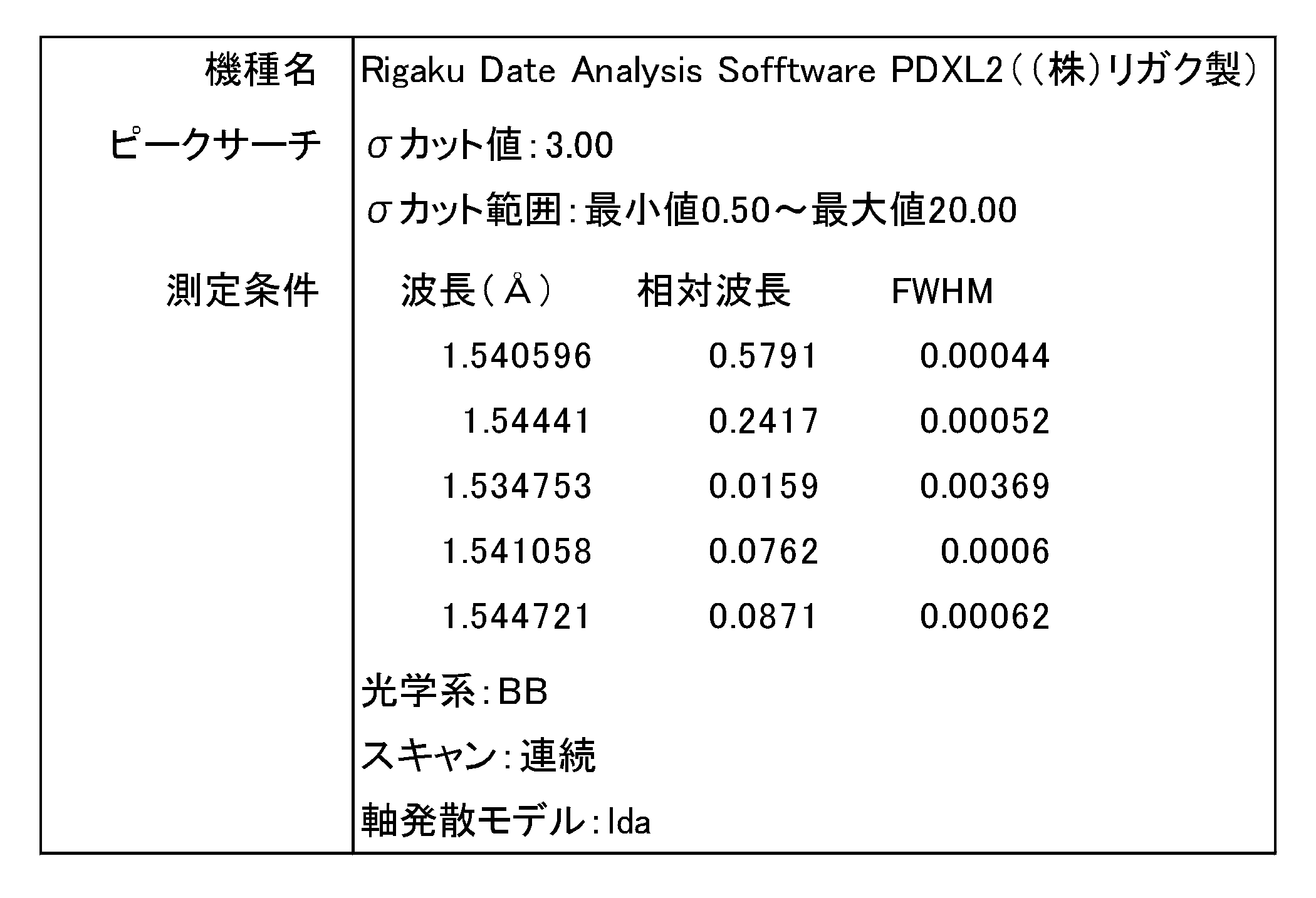
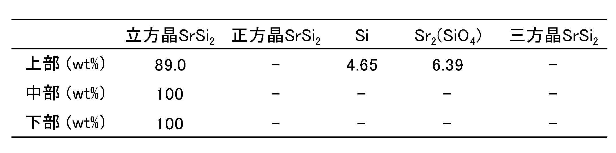
表2に示すとおり、上部試料の結晶相にはSi相及びSr2(SiO4)相が含まれていたが、中部試料及び下部試料は結晶相が立方晶SrSi2相のみからなるものであった。この中部試料及び下部試料が、上述した本実施形態に係る溶融合成体となり得る。
[バンドギャップ値の測定]
ホール測定装置(ResiTest8300、(株)東陽テクニカ製)を用いて、80~400Kの測定温度における下部試料のキャリア濃度を測定してアレニウスプロットし、280~400Kをフィッテング範囲として、その範囲のプロット線の傾きからバンドギャップ値を算出した。その結果、実施例1の下部試料のバンドギャップ値(Eg)は48.0meVであった。
ホール測定装置(ResiTest8300、(株)東陽テクニカ製)を用いて、80~400Kの測定温度における下部試料のキャリア濃度を測定してアレニウスプロットし、280~400Kをフィッテング範囲として、その範囲のプロット線の傾きからバンドギャップ値を算出した。その結果、実施例1の下部試料のバンドギャップ値(Eg)は48.0meVであった。
<実施例2>
[ストロンチウムシリサイド多結晶体の溶融合成]
実施例2では、溶融合成の条件を以下のように変更したこと以外は実施例1と同様にして、インゴットを得た。
[ストロンチウムシリサイド多結晶体の溶融合成]
実施例2では、溶融合成の条件を以下のように変更したこと以外は実施例1と同様にして、インゴットを得た。
ストロンチウムシリサイド多結晶体の溶融合成に際しては、まず、加熱部を下端から106mmの位置に固定した上で、上段のヒーター(ヒーター21A)及び中段のヒーター(ヒーター21B)の温度を1130℃に設定するとともに、下段のヒーター(ヒーター21C)の温度を890℃に設定した。坩堝直下の温度は90分後に1050℃に達した。その状態で10時間保持し、組成原料の固相液相反応を進行させ、SrSi2を合成した(固相液相反応工程)。
次いで、加熱部を15分間かけて下端(0mmの位置)まで移動させた。そのときの坩堝直下の温度は1133℃であった。その状態で5時間保持し、SrSi2の融解液を得た(融解工程)。
次いで、加熱部を下端(0mmの位置)から上端(200mmの位置)まで1.08mm/hの移動速度で移動させることによって融解液の温度を徐々に降下させ、融解液から結晶を育成させた(結晶育成工程)。融解液の降温速度は、1100℃に達するまでは平均0.617℃/h(最小:0.445℃/h、最大:0.745℃/h)であり、1100℃に達した後、1015℃に達するまでは平均1.152℃/h(最小:0.988℃/h、最大:1.339℃/h)であった。
その後、上段、中段、及び下段の各ヒーターの温度をいずれも600℃に設定し、5時間かけて坩堝直下の温度を600℃まで降下させた。さらに、上段、中段、及び下段の各ヒーターの温度をいずれも25℃に設定し、5時間かけて坩堝直下の温度を25℃まで降下させた後、坩堝からインゴットを取り出した。得られたインゴットは、目視でボイドが観察されないものであった。
[粉末X線回折分析及びリートベルト解析]
得られたインゴットのうち、結晶成長の終端側である上部側(坩堝の口部側)の約1/5の部分を、坩堝の高さ方向に垂直にワイヤーソーで切断し、上部試料とした。さらに、残りの部分を、坩堝の高さ方向に垂直にワイヤーソーで半分に切断し、中部試料及び下部試料とした。そして、各試料の一部を粉末化し、実施例1と同様にして粉末X線回折分析を行った。
得られたインゴットのうち、結晶成長の終端側である上部側(坩堝の口部側)の約1/5の部分を、坩堝の高さ方向に垂直にワイヤーソーで切断し、上部試料とした。さらに、残りの部分を、坩堝の高さ方向に垂直にワイヤーソーで半分に切断し、中部試料及び下部試料とした。そして、各試料の一部を粉末化し、実施例1と同様にして粉末X線回折分析を行った。
各試料の粉末X線回折パターンを図8A及び図8Bに示す。図8A及び図8Bに示すとおり、上部試料には不純物としてSi及びSr2(SiO4)が確認されたが、中部試料及び下部試料には不純物が確認されなかった。この結果から、不純物がインゴットの上部側(結晶成長の終端側)に偏析していることが分かる。
さらに、実施例1と同様にして粉末X線回折パターンのリートベルト解析を行った。リートベルト解析による定量値を下記表3に示す。
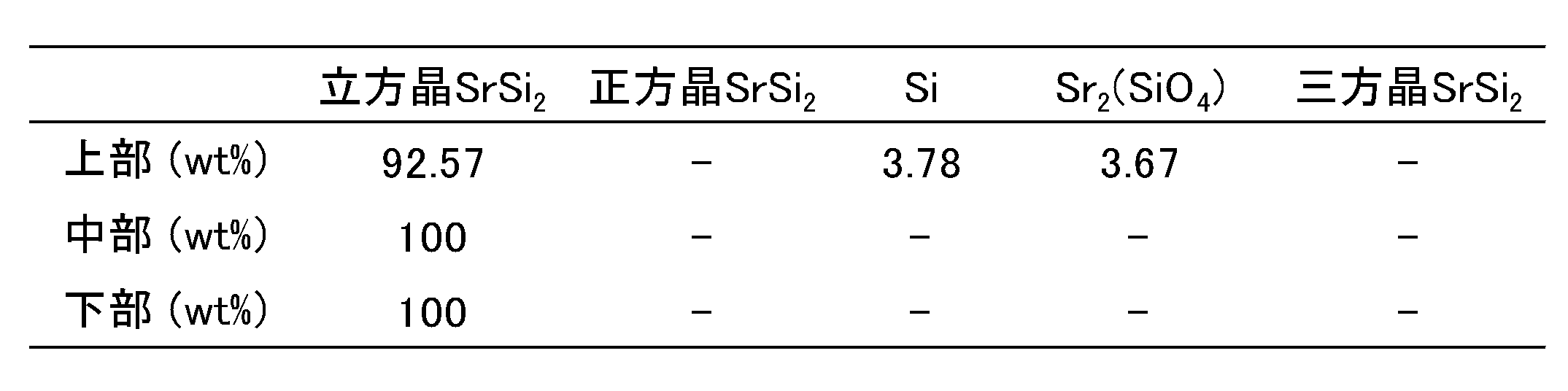
表3に示すとおり、上部試料の結晶相にはSi相及びSr2(SiO4)相が含まれていたが、中部試料及び下部試料は結晶相が立方晶SrSi2相のみからなるものであった。この中部試料及び下部試料が、上述した本実施形態に係る溶融合成体となり得る。
[バンドギャップ値の測定]
実施例1と同様にして、実施例2の下部試料のバンドギャップ値を測定した。その結果、実施例2の下部試料のバンドギャップ値(Eg)は49.4meVであった。
実施例1と同様にして、実施例2の下部試料のバンドギャップ値を測定した。その結果、実施例2の下部試料のバンドギャップ値(Eg)は49.4meVであった。
<実施例3>
[焼結体の製造]
Arガス雰囲気のグローブボックス内にて、実施例1の下部試料の一部を、乳鉢を用いて粉砕した。粉砕後、ステンレス製篩を用いて分級し、粒径25~45μmの試料粉末を得た。
[焼結体の製造]
Arガス雰囲気のグローブボックス内にて、実施例1の下部試料の一部を、乳鉢を用いて粉砕した。粉砕後、ステンレス製篩を用いて分級し、粒径25~45μmの試料粉末を得た。
内径10.4mmのグラファイト製ダイ((株)ウエキコーポレーション製)と、上下2つのグラファイト製パンチ((株)ウエキコーポレーション製)とで囲まれた空間に、試料粉末3.75gを仕込んだ(図3参照)。粉末の上下端には、パンチへの固着防止のためにカーボンペーパーを挟んだ。この状態で、足踏み式油圧プレス機(理研精機(株)製)を用いて60MPaの圧力でプレスし、圧粉体とした。
次いで、グラファイト製ダイを放電プラズマ焼結装置(Ed-PAS III、(株)エレニックス製)に設置し、プレス圧力を100MPaに昇圧し、Ar雰囲気下で放電プラズマ焼結を行った。焼結時の温度条件は以下のとおりである。まず、室温から500℃まで1分間かけて昇温した後、800℃まで1分間かけて昇温した。次いで、焼結温度である920℃に達するまで30℃/minの昇温速度で昇温し、920℃で10分間保持した。次いで、600℃に達するまで50℃/minの降温速度で降温し、その間に42MPaになるまで徐々にプレス圧力を低下させた。その後、室温まで放冷した。なお、温度測定は、グラファイト製ダイの温度を測定することにより行い、室温から580℃まではK熱電対を使用し、それ以上の温度では赤外線放射温度計を使用した。
焼結後、付着したカーボンペーパーをサンドペーパーで除去することにより、焼結体を得た。得られた焼結体の形状は、円柱状(上面及び底面が直径10mmの円、高さが5mm)である。
<熱電変換性能の評価>
実施例1及び2の下部試料を、坩堝の高さ方向に垂直にワイヤーソーで切断し、厚さ2mmの略円盤状の試料を得た。さらに、ワイヤーソーを用いて、略円盤状の試料から2mm×2mm×7.5mmの大きさの試験片を切り出した。また、実施例3の焼結体を、円柱の軸方向に垂直にワイヤーソーで切断し、厚さ2mmの円盤状の試料を得た。さらに、ワイヤーソーを用いて、円盤状の試料から2mm×2mm×7.5mmの大きさの試験片を切り出した。
実施例1及び2の下部試料を、坩堝の高さ方向に垂直にワイヤーソーで切断し、厚さ2mmの略円盤状の試料を得た。さらに、ワイヤーソーを用いて、略円盤状の試料から2mm×2mm×7.5mmの大きさの試験片を切り出した。また、実施例3の焼結体を、円柱の軸方向に垂直にワイヤーソーで切断し、厚さ2mmの円盤状の試料を得た。さらに、ワイヤーソーを用いて、円盤状の試料から2mm×2mm×7.5mmの大きさの試験片を切り出した。
実施例1~3の各試験片について、熱電特性評価装置(ZEM-3、アドバンス理工(株)製)を用いて、300~600Kの温度範囲におけるゼーベック係数及び電気伝導率を測定した。そして、得られたゼーベック係数及び電気伝導率に基づいて出力因子を算出した。実施例1~3の各試験片のゼーベック係数、電気伝導率、及び出力因子を図9~11に示す。図11から分かるように、実施例1~3の各試験片は、低温領域で高い熱電変換性能を有していた。310Kにおける出力因子は、実施例1が2.736×10⁻³W/mK2、実施例2が2.919×10-3W/mK2、実施例3が2.845×10-3W/mK2であった。
<実施例4>
[ストロンチウムシリサイド多結晶体の溶融合成]
実施例4では、組成原料を装填する坩堝をアルミナ製の坩堝((株)ニッカトー製)の内表面に窒化ホウ素を押し固めたものに変更し、加熱炉内部の充填ガスを5体積%の水素ガスを含むArガスに変更し、溶融合成の条件を以下のように変更したこと以外は実施例1と同様にして、インゴットを得た。
[ストロンチウムシリサイド多結晶体の溶融合成]
実施例4では、組成原料を装填する坩堝をアルミナ製の坩堝((株)ニッカトー製)の内表面に窒化ホウ素を押し固めたものに変更し、加熱炉内部の充填ガスを5体積%の水素ガスを含むArガスに変更し、溶融合成の条件を以下のように変更したこと以外は実施例1と同様にして、インゴットを得た。
ストロンチウムシリサイド多結晶体の溶融合成に際しては、まず、加熱部を下端から123mmの位置に固定した上で、上段のヒーター(ヒーター21A)及び中段のヒーター(ヒーター21B)の温度を1130℃に設定するとともに、下段のヒーター(ヒーター21C)の温度を890℃に設定した。坩堝直下の温度は90分後に1035℃に達した。その状態で10時間保持し、組成原料の固相液相反応を進行させ、SrSi2を合成した(固相液相反応工程)。
次いで、加熱部を15分間かけて下端(0mmの位置)まで移動させた。そのときの坩堝直下の温度は1130℃であった。その状態で5時間保持し、SrSi2の融解液を得た(融解工程)。
次いで、加熱部を下端(0mmの位置)から上端(200mmの位置)まで3.6mm/hの移動速度で移動させることによって融解液の温度を徐々に降下させ、融解液から結晶を育成させた(結晶育成工程)。融解液の降温速度は、1100℃に達するまでは平均1.84℃/h(最小:1.23℃/h、最大:2.36℃/h)であり、1100℃に達した後、1000℃に達するまでは平均4.32℃/h(最小:3.01℃/h、最大:5.19℃/h)であった。
その後、上段、中段、及び下段の各ヒーターの温度をいずれも600℃に設定し、5時間かけて坩堝直下の温度を600℃まで降下させた。さらに、上段、中段、及び下段の各ヒーターの温度をいずれも25℃に設定し、5時間かけて坩堝直下の温度を25℃まで降下させた後、坩堝からインゴットを取り出した。得られたインゴットは、目視でボイドが観察されないものであった。得られたインゴットを走査型電子顕微鏡(SEM)で観察した反射電子像及び二次電子像を図12に示す。
[粉末X線回折分析及びリートベルト解析]
得られたインゴットのうち、結晶成長の終端側である上部側(坩堝の口部側)の約1/5の部分を、坩堝の高さ方向に垂直にワイヤーソーで切断し、上部試料とした。さらに、残りの部分を、坩堝の高さ方向に垂直にワイヤーソーで半分に切断し、中部試料及び下部試料とした。そして、各試料の一部を粉末化し、実施例1と同様にして粉末X線回折分析を行った。
得られたインゴットのうち、結晶成長の終端側である上部側(坩堝の口部側)の約1/5の部分を、坩堝の高さ方向に垂直にワイヤーソーで切断し、上部試料とした。さらに、残りの部分を、坩堝の高さ方向に垂直にワイヤーソーで半分に切断し、中部試料及び下部試料とした。そして、各試料の一部を粉末化し、実施例1と同様にして粉末X線回折分析を行った。
各試料の粉末X線回折パターンを図13A及び図13Bに示す。図13A及び図13Bに示すとおり、上部試料には不純物としてSiが確認されたが、中部試料及び下部試料には不純物が確認されなかった。この結果から、不純物がインゴットの上部側(結晶成長の終端側)に偏析していることが分かる。
さらに、実施例1と同様にして粉末X線回折パターンのリートベルト解析を行った。リートベルト解析による定量値を下記表4に示す。

表4に示すとおり、上部試料の結晶相にはSi相が含まれていたが、中部試料及び下部試料は結晶相が立方晶SrSi2相のみからなるものであった。この中部試料及び下部試料が、上述した本実施形態に係る溶融合成体となり得る。
[バンドギャップ値の測定]
実施例1と同様にして、実施例4の下部試料のバンドギャップ値を測定した。その結果、実施例4の下部試料のバンドギャップ値(Eg)は49.4meVであった。
実施例1と同様にして、実施例4の下部試料のバンドギャップ値を測定した。その結果、実施例4の下部試料のバンドギャップ値(Eg)は49.4meVであった。
[ヤング率及び破壊靭性値の測定]
実施例4の下部試料について、Hillの近似式を用いた密度汎関数理論(DFT)に基づき、次式:E=9BG/(3B+G)に従ってヤング率Eを求めた。式中、Gは剪断弾性率(Gpa)を示し、Bは等方性体積弾性率(Gpa)を示す。また、実施例4の下部試料について、JIS R 1607:2015のIF法に準じて破壊靭性値を測定した。その結果、実施例4の下部試料のヤング率は90.17GPaであり、破壊靭性値は1.452MPa・m1/2であった。
実施例4の下部試料について、Hillの近似式を用いた密度汎関数理論(DFT)に基づき、次式:E=9BG/(3B+G)に従ってヤング率Eを求めた。式中、Gは剪断弾性率(Gpa)を示し、Bは等方性体積弾性率(Gpa)を示す。また、実施例4の下部試料について、JIS R 1607:2015のIF法に準じて破壊靭性値を測定した。その結果、実施例4の下部試料のヤング率は90.17GPaであり、破壊靭性値は1.452MPa・m1/2であった。
<実施例5>
[ストロンチウムシリサイド多結晶体の溶融合成]
実施例5では、溶融合成の条件を以下のように変更したこと以外は実施例4と同様にして、インゴットを得た。
[ストロンチウムシリサイド多結晶体の溶融合成]
実施例5では、溶融合成の条件を以下のように変更したこと以外は実施例4と同様にして、インゴットを得た。
ストロンチウムシリサイド多結晶体の溶融合成に際しては、まず、加熱部を下端から106mmの位置に固定した上で、上段のヒーター(ヒーター21A)及び中段のヒーター(ヒーター21B)の温度を1130℃に設定するとともに、下段のヒーター(ヒーター21C)の温度を890℃に設定した。坩堝直下の温度は90分後に1035℃に達した。その状態で10時間保持し、組成原料の固相液相反応を進行させ、SrSi2を合成した(固相液相反応工程)。
次いで、加熱部を15分間かけて下端(0mmの位置)まで移動させた。そのときの坩堝直下の温度は1130℃であった。その状態で5時間保持し、SrSi2の融解液を得た(融解工程)。
次いで、加熱部を下端(0mmの位置)から上端(200mmの位置)まで1.08mm/hの移動速度で移動させることによって融解液の温度を徐々に降下させ、融解液から結晶を育成させた(結晶育成工程)。融解液の降温速度は、1100℃に達するまでは平均0.617℃/h(最小:0.445℃/h、最大:0.745℃/h)であり、1100℃に達した後、1015℃に達するまでは平均1.152℃/h(最小:0.988℃/h、最大:1.339℃/h)であった。
その後、上段、中段、及び下段の各ヒーターの温度をいずれも600℃に設定し、5時間かけて坩堝直下の温度を600℃まで降下させた。さらに、上段、中段、及び下段の各ヒーターの温度をいずれも25℃に設定し、5時間かけて坩堝直下の温度を25℃まで降下させた後、坩堝からインゴットを取り出した。得られたインゴットは、目視でボイドが観察されないものであった。得られたインゴットをSEMで観察した反射電子像及び二次電子像を図14に示す。
[粉末X線回折分析及びリートベルト解析]
得られたインゴットのうち、結晶成長の終端側である上部側(坩堝の口部側)の約1/5の部分を、坩堝の高さ方向に垂直にワイヤーソーで切断し、上部試料とした。さらに、残りの部分を、坩堝の高さ方向に垂直にワイヤーソーで半分に切断し、中部試料及び下部試料とした。そして、各試料の一部を粉末化し、実施例1と同様にして粉末X線回折分析を行った。
得られたインゴットのうち、結晶成長の終端側である上部側(坩堝の口部側)の約1/5の部分を、坩堝の高さ方向に垂直にワイヤーソーで切断し、上部試料とした。さらに、残りの部分を、坩堝の高さ方向に垂直にワイヤーソーで半分に切断し、中部試料及び下部試料とした。そして、各試料の一部を粉末化し、実施例1と同様にして粉末X線回折分析を行った。
各試料の粉末X線回折パターンを図15A及び図15Bに示す。図15A及び図15Bに示すとおり、上部試料には不純物としてSiが確認されたが、中部試料及び下部試料には不純物が確認されなかった。この結果から、不純物がインゴットの上部側(結晶成長の終端側)に偏析していることが分かる。
さらに、実施例1と同様にして粉末X線回折パターンのリートベルト解析を行った。リートベルト解析による定量値を下記表5に示す。

表5に示すとおり、上部試料の結晶相にはSi相が含まれていたが、中部試料及び下部試料は結晶相が立方晶SrSi2相のみからなるものであった。この中部試料及び下部試料が、上述した本実施形態に係る溶融合成体となり得る。
[バンドギャップ値の測定]
実施例1と同様にして、実施例5の下部試料のバンドギャップ値を測定した。その結果、実施例5の下部試料のバンドギャップ値(Eg)は46.1meVであった。
実施例1と同様にして、実施例5の下部試料のバンドギャップ値を測定した。その結果、実施例5の下部試料のバンドギャップ値(Eg)は46.1meVであった。
[ヤング率及び破壊靭性値の測定]
実施例4と同様にして、実施例5の下部試料のヤング率及び破壊靭性値を測定した。その結果、実施例5の下部試料のヤング率は91.14GPaであり、破壊靭性値は1.370MPa・m1/2であった。
実施例4と同様にして、実施例5の下部試料のヤング率及び破壊靭性値を測定した。その結果、実施例5の下部試料のヤング率は91.14GPaであり、破壊靭性値は1.370MPa・m1/2であった。
<比較例1>
[ストロンチウムシリサイド多結晶体の溶融合成]
比較例1では、ストロンチウムとシリコンとの原子量比を33.8:66.2に変更し、加熱炉内部の充填ガスをArガスに変更し、溶融合成の条件を以下のように変更したこと以外は実施例4と同様にして、インゴットを得た。
[ストロンチウムシリサイド多結晶体の溶融合成]
比較例1では、ストロンチウムとシリコンとの原子量比を33.8:66.2に変更し、加熱炉内部の充填ガスをArガスに変更し、溶融合成の条件を以下のように変更したこと以外は実施例4と同様にして、インゴットを得た。
ストロンチウムシリサイド多結晶体の溶融合成に際しては、まず、加熱部を下端から197mmの位置に固定した上で、上段のヒーター(ヒーター21A)の温度を1100℃、中段のヒーター(ヒーター21B)の温度を1130℃、下段のヒーター(ヒーター21C)の温度を890℃にそれぞれ設定した。坩堝直下の温度は90分後に900℃に達した。その状態で3時間保持し、組成原料の固相液相反応を進行させ、SrSi2を合成した。
次いで、加熱部を15分間かけて下端(0mmの位置)まで移動させた。そのときの坩堝直下の温度は1130℃であった。その状態で3時間保持し、SrSi2の融解液を得た。
次いで、加熱部を下端(0mmの位置)から上端(200mmの位置)まで7.2mm/hの移動速度で移動させることによって融解液の温度を徐々に降下させ、融解液から結晶を育成させた(結晶育成工程)。融解液の降温速度は、1100℃に達するまでは平均2.13℃/h(最小:0.88℃/h、最大:3.35℃/h)であり、1100℃に達した後、1000℃に達するまでは平均7.02℃/h(最小:3.56℃/h、最大:9.73℃/h)であった。
その後、上段、中段、及び下段の各ヒーターの温度をいずれも600℃に設定し、5時間かけて坩堝直下の温度を600℃まで降下させた。さらに、上段、中段、及び下段の各ヒーターの温度をいずれも25℃に設定し、5時間かけて坩堝直下の温度を25℃まで降下させた後、坩堝からインゴットを取り出した。
[粉末X線回折分析及びリートベルト解析]
得られたインゴットのうち、結晶成長の始端側である下部側(坩堝の底部側)から粉末状の試料を回収した。そして、実施例1と同様にして粉末X線回折分析を行った。
得られたインゴットのうち、結晶成長の始端側である下部側(坩堝の底部側)から粉末状の試料を回収した。そして、実施例1と同様にして粉末X線回折分析を行った。
比較例1の試料の粉末X線回折パターンを図16A及び図16Bに示す。図16A及び図16Bに示すとおり、比較例1の試料には正方晶SrSi2が確認された。
さらに、実施例1と同様にして粉末X線回折パターンのリートベルト解析を行った。リートベルト解析による定量値を下記表6に示す。

表6に示すとおり、比較例1の試料の結晶相には1.88質量%の正方晶SrSi2相が含まれていた。
[バンドギャップ値の測定]
実施例1と同様にして、比較例1の試料のバンドギャップ値を測定した。その結果、比較例1の試料のバンドギャップ値(Eg)は30.9meVであった。
実施例1と同様にして、比較例1の試料のバンドギャップ値を測定した。その結果、比較例1の試料のバンドギャップ値(Eg)は30.9meVであった。
<比較例2>
[ストロンチウムシリサイド多結晶体の溶融合成]
比較例2では、溶融合成の条件を以下のように変更したこと以外は実施例4と同様にして、インゴットを得た。
[ストロンチウムシリサイド多結晶体の溶融合成]
比較例2では、溶融合成の条件を以下のように変更したこと以外は実施例4と同様にして、インゴットを得た。
ストロンチウムシリサイド多結晶体の溶融合成に際しては、まず、加熱部を下端(0mmの位置)に固定した上で、上段のヒーター(ヒーター21A)及び中段のヒーター(ヒーター21B)の温度を1130℃に設定するとともに、下段のヒーター(ヒーター21C)の温度を890℃に設定した。坩堝直下の温度は90分後に1130℃に達した。その状態で5時間保持し、SrSi2を合成しながらSrSi2の融解液を得た。
次いで、加熱部を下端(0mmの位置)から上端(200mmの位置)まで3.6mm/hの移動速度で移動させることによって融解液の温度を徐々に降下させ、融解液から結晶を育成させた。融解液の降温速度は、1100℃に達するまでは平均1.84℃/h(最小:1.23℃/h、最大:2.36℃/h)であり、1100℃に達した後、1000℃に達するまでは平均4.32℃/h(最小:3.01℃/h、最大:5.19℃/h)であった。
その後、上段、中段、及び下段の各ヒーターの温度をいずれも600℃に設定し、5時間かけて坩堝直下の温度を600℃まで降下させた。さらに、上段、中段、及び下段の各ヒーターの温度をいずれも25℃に設定し、5時間かけて坩堝直下の温度を25℃まで降下させた後、坩堝からインゴットを取り出した。
[粉末X線回折分析]
得られたインゴットのうち、結晶成長の始端側である下部側(坩堝の底部側)の異なる2箇所から粉末状の試料1及び2を回収した。そして、実施例1と同様にして粉末X線回折分析を行った。
得られたインゴットのうち、結晶成長の始端側である下部側(坩堝の底部側)の異なる2箇所から粉末状の試料1及び2を回収した。そして、実施例1と同様にして粉末X線回折分析を行った。
比較例2の試料1及び2の粉末X線回折パターンを図17に示す。図17に示すとおり、試料1及び2のいずれについても、正方晶SrSi2やその他の不純物が多く確認された。
<熱電変換性能の評価>
実施例4及び5の下部試料を、坩堝の高さ方向に垂直にワイヤーソーで切断し、厚さ2mmの略円盤状の試料を得た。さらに、ワイヤーソーを用いて、略円盤状の試料から2mm×2mm×7.5mmの大きさの試験片を切り出した。また、比較例1のインゴットから同様にして試験片を切り出した。
実施例4及び5の下部試料を、坩堝の高さ方向に垂直にワイヤーソーで切断し、厚さ2mmの略円盤状の試料を得た。さらに、ワイヤーソーを用いて、略円盤状の試料から2mm×2mm×7.5mmの大きさの試験片を切り出した。また、比較例1のインゴットから同様にして試験片を切り出した。
実施例4及び5並びに比較例1の各試験片について、熱電特性評価装置(ZEM-3、アドバンス理工(株)製)を用いて、300~600Kの温度範囲におけるゼーベック係数及び電気伝導率を測定した。そして、得られたゼーベック係数及び電気伝導率に基づいて出力因子を算出した。実施例4及び5並びに比較例1の各試験片のゼーベック係数、電気伝導率、及び出力因子を図18~20に示す。図20から分かるように、実施例4及び5の各試験片は、低温領域で高い熱電変換性能を有していた。310Kにおける出力因子は、実施例4が2.707×10⁻³W/mK2、実施例5が2.893×10-3W/mK2、比較例1が2.275×10-3W/mK2であった。
<実施例6~8>
[焼結体の製造]
実施例6~8では、実施例5の下部試料の一部を使用し、焼結時の温度条件を以下のように変更したこと以外は実施例3と同様にして、焼結体を得た。
[焼結体の製造]
実施例6~8では、実施例5の下部試料の一部を使用し、焼結時の温度条件を以下のように変更したこと以外は実施例3と同様にして、焼結体を得た。
焼結に際しては、まず、室温から500℃まで1分間かけて昇温した後、800℃まで1分間かけて昇温した。次いで、焼結温度である890℃(実施例6)、920℃(実施例7)、又は950℃(実施例8)に達するまで30℃/minの昇温速度で昇温し、各焼結温度で10分間保持した。次いで、600℃に達するまで50℃/minの降温速度で降温し、その間に42MPaになるまで徐々にプレス圧力を低下させた。その後、室温まで放冷し、焼結体を得た。
実施例6~8の焼結体を光学顕微鏡で観察した光学顕微鏡像及びSEMで観察した反射電子像を図21に示す。図21から分かるように、焼結温度が高いほどボイドが少なく、粒界の密着性が高かった。
[相対密度の測定]
アルキメデス法により、実施例6~8の焼結体の見かけ密度を測定した。また、ガスピクノメーターを用いたガス置換法により、実施例6~8の焼結体の真密度を測定した。そして、真密度に対する見かけ密度の割合から、相対密度を算出した。その結果、焼結体の相対密度は、実施例6が97.6%、実施例7が97.7%、実施例8が99.7%であった。
アルキメデス法により、実施例6~8の焼結体の見かけ密度を測定した。また、ガスピクノメーターを用いたガス置換法により、実施例6~8の焼結体の真密度を測定した。そして、真密度に対する見かけ密度の割合から、相対密度を算出した。その結果、焼結体の相対密度は、実施例6が97.6%、実施例7が97.7%、実施例8が99.7%であった。
[粉末X線回折分析及びリートベルト解析]
実施例6~8の焼結体の端部を粉末化し、実施例1と同様にして粉末X線回折分析を行った。
実施例6~8の焼結体の端部を粉末化し、実施例1と同様にして粉末X線回折分析を行った。
実施例6~8の焼結体の粉末X線回折パターンを図22A及び図22Bに示す。図22A及び図22Bに示すとおり、実施例8の焼結体には不純物としてSiが確認されたが、実施例6及び7の焼結体には不純物が確認されなかった。
さらに、実施例1と同様にして粉末X線回折パターンのリートベルト解析を行った。リートベルト解析による定量値を下記表7に示す。
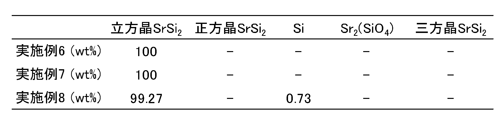
表7に示すとおり、実施例8の焼結体の結晶相にはSi相が僅かに含まれていたが、実施例6及び7の焼結体は結晶相が立方晶SrSi2相のみからなるものであった。
[バンドギャップ値の測定]
実施例1と同様にして、実施例6~8の焼結体のバンドギャップ値を測定した。その結果、バンドギャップ値(Eg)は、実施例6が55.8meV、実施例7が53.8meV、実施例8が52.6meVであった。
実施例1と同様にして、実施例6~8の焼結体のバンドギャップ値を測定した。その結果、バンドギャップ値(Eg)は、実施例6が55.8meV、実施例7が53.8meV、実施例8が52.6meVであった。
[ヤング率及び破壊靭性値の測定]
実施例4と同様にして、実施例6~8の焼結体のヤング率及び破壊靭性値を測定した。その結果、ヤング率は、実施例6が86.92GPa、実施例7が88.56GPa、実施例8が87.32GPaであった。また、破壊靭性値は、実施例6が1.445MPa・m1/2、実施例7が1.650MPa・m1/2、実施例8が1.445MPa・m1/2であった。
実施例4と同様にして、実施例6~8の焼結体のヤング率及び破壊靭性値を測定した。その結果、ヤング率は、実施例6が86.92GPa、実施例7が88.56GPa、実施例8が87.32GPaであった。また、破壊靭性値は、実施例6が1.445MPa・m1/2、実施例7が1.650MPa・m1/2、実施例8が1.445MPa・m1/2であった。
<比較例3>
[焼結体の製造]
比較例3では、比較例2の試料1を使用したこと以外は実施例3と同様にして、焼結体を得た。
[焼結体の製造]
比較例3では、比較例2の試料1を使用したこと以外は実施例3と同様にして、焼結体を得た。
<熱電変換性能の評価>
実施例6~8及び比較例3の焼結体を、円柱の軸方向に垂直にワイヤーソーで切断し、厚さ2mmの円盤状の試料を得た。さらに、ワイヤーソーを用いて、円盤状の試料から2mm×2mm×7.5mmの大きさの試験片を切り出した。
実施例6~8及び比較例3の焼結体を、円柱の軸方向に垂直にワイヤーソーで切断し、厚さ2mmの円盤状の試料を得た。さらに、ワイヤーソーを用いて、円盤状の試料から2mm×2mm×7.5mmの大きさの試験片を切り出した。
実施例6~8及び比較例3の各試験片について、熱電特性評価装置(ZEM-3、アドバンス理工(株)製)を用いて、300~600Kの温度範囲におけるゼーベック係数及び電気伝導率を測定した。そして、得られたゼーベック係数及び電気伝導率に基づいて出力因子を算出した。実施例6~8及び比較例3の各試験片のゼーベック係数、電気伝導率、及び出力因子を図23~25に示す。図25から分かるように、実施例6~8の各試験片は、低温領域で高い熱電変換性能を有していた。310Kにおける出力因子は、実施例6が2.401×10⁻³W/mK2、実施例7が2.571×10-3W/mK2、実施例8が2.442×10-3W/mK2、比較例3が1.814×10-3W/mK2であった。
1 垂直ブリッジマン炉
10 炉本体
11 石英ガラス管
12 グラファイト製試料台
13 遮熱板
14 熱電対
20 加熱部
21A、21B、21C ヒーター
22 断熱材
23A、23B、23C 熱電対
30 坩堝
31 石英製カバー
50 グラファイト製ダイ
51a、51b グラファイト製パンチ
100 n型熱電変換部
101、102 電極
110 p型熱電変換部
111、112 電極
120 熱電変換部
121、122 電極
130 負荷
10 炉本体
11 石英ガラス管
12 グラファイト製試料台
13 遮熱板
14 熱電対
20 加熱部
21A、21B、21C ヒーター
22 断熱材
23A、23B、23C 熱電対
30 坩堝
31 石英製カバー
50 グラファイト製ダイ
51a、51b グラファイト製パンチ
100 n型熱電変換部
101、102 電極
110 p型熱電変換部
111、112 電極
120 熱電変換部
121、122 電極
130 負荷
Claims (18)
- ストロンチウムシリサイド多結晶体から構成される熱電変換性溶融合成体であって、
粉末X線回折パターンのリートベルト解析による定量値として、立方晶SrSi2相の含有率が99.0質量%以上であり、正方晶SrSi2相及び三方晶SrSi2相の含有率がいずれも0.1質量%未満である熱電変換性溶融合成体。 - 粉末X線回折パターンのリートベルト解析による定量値として、Siの含有率が0.1質量%未満である、請求項1に記載の熱電変換性溶融合成体。
- 粉末X線回折パターンのリートベルト解析による定量値として、Srの含有率が0.1質量%未満である、請求項1に記載の熱電変換性溶融合成体。
- 310Kにおける出力因子が2.50×10⁻³W/mK2以上である、請求項1に記載の熱電変換性溶融合成体。
- バンドギャップが45.0meV以上である、請求項1に記載の熱電変換性溶融合成体。
- ストロンチウムシリサイド多結晶体から構成される熱電変換性焼結体であって、
粉末X線回折パターンのリートベルト解析による定量値として、立方晶SrSi2相の含有率が99.0質量%以上であり、正方晶SrSi2相及び三方晶SrSi2相の含有率がいずれも0.1質量%未満である熱電変換性焼結体。 - 請求項1に記載の熱電変換性溶融合成体を焼結してなる、請求項6に記載の熱電変換性焼結体。
- 粉末X線回折パターンのリートベルト解析による定量値として、Siの含有率が0.8質量%未満である、請求項6に記載の熱電変換性焼結体。
- 粉末X線回折パターンのリートベルト解析による定量値として、Srの含有率が0.1質量%未満である、請求項6に記載の熱電変換性焼結体。
- 310Kにおける出力因子が2.35×10⁻³W/mK2以上である、請求項6に記載の熱電変換性焼結体。
- バンドギャップが50.0meV以上である、請求項6に記載の熱電変換性焼結体。
- 請求項1~5のいずれか1項に記載の熱電変換性溶融合成体、又は請求項6~11のいずれか1項に記載の熱電変換性焼結体から構成される熱電変換部と、
前記熱電変換部に設けられる第1電極及び第2電極と、
を備える熱電変換素子。 - 請求項12に記載の熱電変換素子を備える熱電変換モジュール。
- 請求項1~5のいずれか1項に記載の熱電変換性溶融合成体の製造方法であって、
ストロンチウム及びシリコンを含有する組成原料を1000℃以上SrSi2の融点未満の温度で加熱し、SrSi2を合成する固相液相反応工程と、
前記固相液相反応工程で合成されたSrSi2を加熱し、融解液を得る融解工程と、
前記融解液から結晶を育成させてストロンチウムシリサイド多結晶体を得る結晶育成工程と、
を含む熱電変換性溶融合成体の製造方法。 - 前記組成原料中のストロンチウムとシリコンとの原子量比が33.0:67.0~34.5:65.5である、請求項14に記載の熱電変換性溶融合成体の製造方法。
- 前記結晶育成工程では、前記融解液の温度が1100℃に達するまでは0.223~4.72℃/hの降温速度で、前記融解液の温度が1100℃に達した後、1000℃に達するまでは0.494~10.38℃/hの降温速度で、前記融解液の温度を降下させる、請求項14に記載の熱電変換性溶融合成体の製造方法。
- 前記固相液相反応工程、前記融解工程、及び前記結晶育成工程が垂直ブリッジマン炉を用いて実施される、請求項14に記載の熱電変換性溶融合成体の製造方法。
- 請求項14に記載の製造方法により得られる熱電変換性溶融合成体を焼結する焼結工程を含む熱電変換性焼結体の製造方法。
Applications Claiming Priority (2)
| Application Number | Priority Date | Filing Date | Title |
|---|---|---|---|
| JP2023096252 | 2023-06-12 | ||
| JP2023-096252 | 2023-06-12 |
Publications (1)
| Publication Number | Publication Date |
|---|---|
| WO2024257738A1 true WO2024257738A1 (ja) | 2024-12-19 |
Family
ID=93852017
Family Applications (1)
| Application Number | Title | Priority Date | Filing Date |
|---|---|---|---|
| PCT/JP2024/021103 Ceased WO2024257738A1 (ja) | 2023-06-12 | 2024-06-10 | 新規な熱電変換性溶融合成体及びその利用 |
Country Status (2)
| Country | Link |
|---|---|
| JP (1) | JP2024178136A (ja) |
| WO (1) | WO2024257738A1 (ja) |
Citations (2)
| Publication number | Priority date | Publication date | Assignee | Title |
|---|---|---|---|---|
| JP2019149523A (ja) * | 2018-02-28 | 2019-09-05 | 東ソー株式会社 | ストロンチウムを含む薄膜及びその製造方法 |
| JP2022051194A (ja) * | 2020-09-18 | 2022-03-31 | 東ソー株式会社 | 珪化物系合金薄膜及びその製造方法 |
-
2024
- 2024-06-10 JP JP2024093895A patent/JP2024178136A/ja active Pending
- 2024-06-10 WO PCT/JP2024/021103 patent/WO2024257738A1/ja not_active Ceased
Patent Citations (2)
| Publication number | Priority date | Publication date | Assignee | Title |
|---|---|---|---|---|
| JP2019149523A (ja) * | 2018-02-28 | 2019-09-05 | 東ソー株式会社 | ストロンチウムを含む薄膜及びその製造方法 |
| JP2022051194A (ja) * | 2020-09-18 | 2022-03-31 | 東ソー株式会社 | 珪化物系合金薄膜及びその製造方法 |
Non-Patent Citations (2)
| Title |
|---|
| IMAI MOTOHARU: "Phase relationship of Sr-Si system around Si concentration of 66.7 at. %", LECTURE PREPRINTS OF THE 68TH JSAP SPRING MEETING. THE JAPAN SOCIETY OF APPLIED PHYSICS, 1 January 2021 (2021-01-01), XP093247167, Retrieved from the Internet <URL:https://www.jstage.jst.go.jp/article/jsapmeeting/2021.1/0/2021.1_2259/_article/-char/ja> * |
| SHIOJIRI DAISHI; IIDA TSUTOMU; KADONO TOMOYUKI; YAMAGUCHI MASATO; KODAMA TAKUYA; YAMAGUCHI SEIYA; TAKAHASHI SHINTA; KAYAMA YUKI; H: "Re-evaluation of the electronic structure and thermoelectric properties of narrow-gap semiconducting α-SrSi2: A complementary experimental and first-principles hybrid-functional approach", JOURNAL OF APPLIED PHYSICS, AMERICAN INSTITUTE OF PHYSICS, 2 HUNTINGTON QUADRANGLE, MELVILLE, NY 11747, vol. 129, no. 11, 15 March 2021 (2021-03-15), 2 Huntington Quadrangle, Melville, NY 11747, XP012254817, ISSN: 0021-8979, DOI: 10.1063/5.0041670 * |
Also Published As
| Publication number | Publication date |
|---|---|
| JP2024178136A (ja) | 2024-12-24 |
Similar Documents
| Publication | Publication Date | Title |
|---|---|---|
| Zheng et al. | High thermoelectric performance of mechanically robust n-type Bi 2 Te 3− x Se x prepared by combustion synthesis | |
| CN108878633A (zh) | 津特耳相热电转换材料 | |
| CN105765748B (zh) | 具有高热电优值的纳米结构的硒化铜及其制备方法 | |
| JP2002285274A (ja) | Mg−Si系熱電材料及びその製造方法 | |
| Chen et al. | Microstructure and thermoelectric properties of n-and p-type doped Mg2Sn compounds prepared by the modified bridgman method | |
| JP7137963B2 (ja) | 半導体焼結体、電気・電子部材、及び半導体焼結体の製造方法 | |
| KR101051010B1 (ko) | p형 Bi-Sb-Te계 열전재료의 제조방법 | |
| WO2018012369A1 (ja) | 多結晶性マグネシウムシリサイドおよびその利用 | |
| Zhu et al. | Enhanced average thermoelectric properties of n‑type Mg3Sb2 based materials by mixed-valence Ni doping | |
| JP7076093B2 (ja) | ストロンチウムを含む薄膜及びその製造方法 | |
| JP7367928B2 (ja) | 熱電変換材料およびその製造方法 | |
| CN112885947B (zh) | 一种n型立方相Ge-Te基热电材料 | |
| US11411155B2 (en) | Thermoelectric conversion material, thermoelectric conversion module using same, and method of manufacturing thermoelectric conversion material | |
| JP5352860B2 (ja) | 熱電材料及びその製造方法 | |
| JP5281308B2 (ja) | 熱電材料及びその製造方法 | |
| JP7562093B2 (ja) | 珪化物系合金薄膜及びその製造方法 | |
| WO2024257738A1 (ja) | 新規な熱電変換性溶融合成体及びその利用 | |
| CN111602257B (zh) | 热电转换材料、热电转换组件和热电转换材料的制造方法 | |
| JP2021036579A (ja) | 熱電変換材料及びその製造方法 | |
| JP2013073960A (ja) | マグネシウムシリサイド、熱電変換材料、焼結体、熱電変換素子用焼結体、熱電変換素子、及び熱電変換モジュール | |
| JP2020167317A (ja) | 多結晶性マグネシウムシリサイド、焼結体及びその利用 | |
| JP5448942B2 (ja) | 熱電変換材料 | |
| JP3580783B2 (ja) | 熱電素子の製造方法及び熱電素子 | |
| KR102560464B1 (ko) | Sn 도핑된 안티몬화 마그네슘 열전 재료의 제조 방법 | |
| US11963448B2 (en) | Method for producing thermoelectric conversion element |
Legal Events
| Date | Code | Title | Description |
|---|---|---|---|
| 121 | Ep: the epo has been informed by wipo that ep was designated in this application |
Ref document number: 24823354 Country of ref document: EP Kind code of ref document: A1 |
|
| NENP | Non-entry into the national phase |
Ref country code: DE |